
CHAPTER 3
Working with Sketches
IN THIS CHAPTER
Distinguishing sketch entities
Creating relationships in sketches
Examining sketch settings
Using sketch blocks in parts, assemblies, and drawings
Using reference geometry
Learning to use sketch relations tutorial
Using blocks and belts tutorial
Referencing geometry tutorial
The workflow for most SolidWorks features goes like this:
- Create a sketch
- Use the sketch to create a feature
- Repeat
So the first step to leaning how to create models in SolidWorks is to learn how to sketch. If you are coming from another parametric 3D modeler, many of your skills will be transferable to SolidWorks. If you are coming from a 2D application, sketching is just like drawing except that you do it in smaller chunks and on planes in 3D space. If you have never used CAD before, think of the sketch-feature relationship as creating a simplified 2D drawing that represents a portion of the part that you can make with some sort of process such as extruding the shape in the 2D drawing, or revolving it.
So far, in this book, you have looked mainly at concepts, settings, and setup, which is necessary but mundane business. In this chapter, you begin to learn how to control parametric relationships in sketches. Then in later chapters, you begin to build models, simple at first, but gaining in complexity and always demonstrating new techniques and features that build your modeling vocabulary. Beyond this, you use the parts to create drawings.
This chapter deals entirely with sketches in parts. However, you will be able to apply many of the topics I cover here to assemblies. Some related topics, such as layout sketches, have functionality that is exclusive to assemblies, and these topics are covered in the assemblies' book, SolidWorks 2011 Assemblies Bible (Wiley, 2011).
When you open a sketch, several tools become available, specifically all the sketch entities and tools. Conversely, you cannot do several things until you open a sketch. For example, you cannot apply a Fillet feature while a sketch is open. Open sketches and selection filters are two very common sources of frustration for new users. Several indicators exist to let you know when you are in Sketch mode:
- The title bar of the SolidWorks window displays the text Sketch X of Part Y.
- The lower-right corner of the status bar displays the text Editing Sketch X.
- The Confirmation Corner displays a sketch icon in the upper-right corner of the graphics window.
- The Sketch toolbar button displays the text Exit Sketch.
- The red sketch Origin displays.
- If you are using the grid, it displays only in Sketch mode.
While most users find the sketch grid annoying or distracting, when teaching, I've always used the grid to remind students when they are in Sketch mode. If you forget or would like a visual cue, the sketch grid is a useful option.
Opening a Sketch
Sketches must be either open or closed, and you can only have one sketch open at a time. SolidWorks uses many indicators to show the state of a sketch, including the Confirmation Corner and the Task Bar.
Several methods exist to open new sketches in SolidWorks:
- Click a sketch entity toolbar button from the Sketch toolbar; SolidWorks prompts you to select a sketch plane. When you select the plane, the sketch opens.
- Preselect a plane or planar face and then click either a sketch entity button or the Sketch button.
- Use the left mouse button to click context toolbar — click a face or plane and select the Sketch icon.
- Use the right mouse button (RMB) to click a plane or planar face and select Insert Sketch. Planes can be selected from either the graphics window or the FeatureManager.
You can open existing sketches several ways:
- Right-click a sketch in the FeatureManager or graphics window, and select Edit Sketch.
- Select a sketch from the FeatureManager or graphics window, and click the Sketch button on the Sketch toolbar.
- Left-click a sketch or feature and click the Edit Sketch icon from the context toolbar.
- Double-click a sketch with the Instant 3D tool active.
Identifying Sketch Entities
The first step in creating most SolidWorks parts is a sketch. This will usually be a 2D sketch, although you can also use 3D sketches. A 2D sketch is simply a collection of 2D lines, arcs, and other elements that lie together on a plane; it usually also contains relations and/or dimensions between the entities so that the sketch can automatically adjust to changes because each sketch entity understands its function.
SolidWorks sketch entities include many types, some of which you will use all the time, and some of which you may not use, even if you spend years working with the software. Next, I identify each entity type. This enables you to see it at least once and know that it is available if you need it at some point.
Using the Sketch toolbar
In the following section, I first identify the default buttons on the Sketch toolbar, followed by the rest of the entities that you can access by choosing Tools ![]() Customize
Customize ![]() Commands
Commands ![]() Sketch.
Sketch.
![]() The Sketch tool opens and closes sketches. You may notice that the name of the button changes depending on if the sketch is open or closed. If you preselect a plane or planar face and then click the Sketch button, SolidWorks opens a new sketch on the plane or face. If you preselect a sketch before clicking the Sketch button, SolidWorks opens this sketch. If you preselect an edge or curve feature before clicking the Sketch button, SolidWorks automatically makes a plane perpendicular to the nearest end of the curve from the location you picked. If you do not use preselection, and only click the Sketch tool with nothing selected, SolidWorks prompts you to select a plane or planar face on which you want to put a new sketch, or an existing sketch to edit.
The Sketch tool opens and closes sketches. You may notice that the name of the button changes depending on if the sketch is open or closed. If you preselect a plane or planar face and then click the Sketch button, SolidWorks opens a new sketch on the plane or face. If you preselect a sketch before clicking the Sketch button, SolidWorks opens this sketch. If you preselect an edge or curve feature before clicking the Sketch button, SolidWorks automatically makes a plane perpendicular to the nearest end of the curve from the location you picked. If you do not use preselection, and only click the Sketch tool with nothing selected, SolidWorks prompts you to select a plane or planar face on which you want to put a new sketch, or an existing sketch to edit.
![]() The 3D Sketch tool opens and closes 3D sketches with no preselection required. 3D sketch is covered in more detail in Chapter 31.
The 3D Sketch tool opens and closes 3D sketches with no preselection required. 3D sketch is covered in more detail in Chapter 31.
![]() The Smart Dimension tool can create all types of dimensions used in SolidWorks, such as horizontal, vertical, aligned, radial, diameter, angle, and arc length. You can create dimensions several ways, as shown in Figure 3.1:
The Smart Dimension tool can create all types of dimensions used in SolidWorks, such as horizontal, vertical, aligned, radial, diameter, angle, and arc length. You can create dimensions several ways, as shown in Figure 3.1:
- By selecting a line and placing the dimension
- By selecting the endpoints of the line and placing the dimension
- By selecting a line and a point and placing the dimension
- By selecting a pair of parallel lines and placing the dimension
FIGURE 3.1 Selection options for linear Smart Dimension

Selecting the line is the easiest and fastest method. Selecting parallel lines on the ends is not recommended because if you delete either of the selected lines, the dimension is also deleted; however, sometimes this method is necessary.
You can use the first and second techniques for the angled line shown in Figure 3.1 to create any of the three dimensions shown. To accomplish this task, drag the cursor while placing the dimension until the witness lines snap to the orientation you want.
Tip
To lock the orientation of a dimension while moving the cursor to place the actual dimension value, click the RMB. To unlock it, click the RMB again. The RMB cursor appears as a lock when the functionality is unavailable and an unlock icon when it is.
The third technique locks you into the horizontal orientation because of the orientation of the selected lines.
Note
In some situations, you may run into lines that appear to be parallel but are not exactly so. This will result in an angle dimension instead of a linear dimension. Here, you can select one of the lines and one endpoint. SolidWorks requires parallelism be precise, and situations where lines aren't exactly parallel happen if the angular measurement is off in the second or third decimal place, measuring in degrees. Imported 2D drawings and reverse-engineered 3D models can be particularly susceptible to this type of error.
Caution
When you select lines to establish a dimension instead of endpoints, both of the lines gain an implied parallel relation that prevents them from moving as you might predict. In the example shown in Figure 3.1, neither of the end lines can be angled unless you remove the dimension.
Another issue with adding dimensions to lines is that if you delete either line, the dimension is also deleted. This is not true for the first and second techniques, where as long as the endpoints remain, the dimension remains.
You can change Smart Dimension values several ways. The most direct way is to simply key in a value such as 4.052. The software assumes document units unless you key in something specific. You could also key in an expression, even with mixed units, such as 8.5 mm/2+.125 or 25.4+.625 in. You can also key in negative dimensions, which function the same as the Change Sense button in the Modify box.
Another way to put a value into the Modify box is to click the down arrow to the right of the value field, and select either to use an equation to calculate a value or a Link Value. A Link Value is like a variable name to which you can assign a value. You can link multiple dimension values to that Link Value. In sheet metal parts, the default Link Value of Thickness is used; if you change the thickness in one feature, it changes for all the sheet metal features.
To the right of the drop-down arrow is a pair of up and down “spin” arrows that enable you to change the value in the Modify box by a set increment amount. You set the increment in Tools ![]() Options
Options ![]() System Options
System Options ![]() Spin Box Increments. You can also store multiple increment values within the Increment Value icon on the Modify box.
Spin Box Increments. You can also store multiple increment values within the Increment Value icon on the Modify box.
The final way to change the value in the Modify box is by using the wheel underneath the value field. The wheel uses the default increment value. Pressing Ctrl while using the wheel multiplies the increment by ten, and pressing Alt while using the wheel divides the increment by ten.
Here is a look at the Dimension Properties interface.
- Radial. You create the dimension by selecting an arc and placing the dimension. If you want a radial dimension of a complete circle, you must right-click the dimension after you create it, select Display Options, and select the Display as Radius/Display as Diameter toggle, as shown in Figure 3.2. Alternatively, you could use the Radius or Diameter leader display options on the Leaders tab of the Dimension PropertyManager.
FIGURE 3.2 The Dimension Properties interface

- Diameter. You can create the dimension by selecting a complete circle and placing the dimension. If you want a diameter dimension for an arc, use the RMB menu or Dimension Properties dialog box and select the Diameter Dimension option.
Note
Along with the Radial and Diameter dimensions, you may also want to dimension between arcs or circles, from tangent or nearest points. To do this, press the Shift key and select the Smart Dimension tool to select the arcs near the tangent points. Alternatively, to change a dimension from a center-to-center dimension to a max-to-max dimension, you can drag dimension attachment points to tangent points or use the dimension properties.
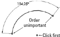
- Angle. You can create the angle dimension one of two ways. If the angle to be driven is between two straight lines, simply select the two straight lines and place the dimension. If you are creating an included angle dimension for an arc where there are not necessarily any straight lines drawn, then with the Smart Dimension tool active, first select the vertex of the angle, and then the two outlying points, as shown in Figure 3.3.
FIGURE 3.3 Creating an included angle dimension
- Arc Length. You can create the dimension by selecting an arc and its endpoints with the Smart Dimension tool.
![]() The Line creates straight lines using one of two methods:
The Line creates straight lines using one of two methods:
- Click+Click. Used for drawing multiple connected end-to-end lines. Click and release the left-mouse button to start the line; each click and release ends the previous line and starts a new one. Double-click, press Esc, or deselect the Line tool to end.
- Click and Drag. Used to draw individual or unconnected lines. Click, drag, and drop. The first click initiates the line, and the drop ends it.
Note
The click+click and click and drag methods have been treated equivalently by SolidWorks until recent releases. Some new functions like Enable on-screen numeric input seem to function better with click+click than click and drag.
Alternate methods for drawing lines include horizontal, vertical, angle, and infinite lines. The interface for these options appears in the PropertyManager, as shown in Figure 3.4.
- Horizontal, Vertical. These settings require you to select a starting point and an ending vertical or horizontal position. There does not seem to be any compelling reason to use this instead of the regular line command.
- Angle. This setting enables you to specify an angle and drag a line at this angle. Again, I can find no compelling reason to use this tool.
- Infinite length. SolidWorks parts have a working space limited to 1000 meters on a side, centered on the Origin. Infinite lines extend well beyond this, although you cannot draw or dimension a regular line outside of this box. I have not come across a compelling use for this feature.
FIGURE 3.4 The Insert Line PropertyManager interface

Note
The Add Dimensions option exists in several sketch entity PropertyManagers and adds Smart Dimensions to newly sketched entities. The option only appears in the sketch entity PropertyManager if the setting at Tools ![]() Options
Options ![]() Sketch
Sketch ![]() Enable on-screen numeric input on entity creation is selected.
Enable on-screen numeric input on entity creation is selected.
The on-screen numeric input is not the same as the Input Dimension Value function, and, in fact, it overrides that option. You cannot input dimension values when using the Add Dimensions in conjunction with click and drag sketching. It appears to be intended for click+click sketching only, so that you can enter values between clicks.
![]() The Corner Rectangle creates a rectangle by clicking one corner and dragging to the diagonal corner. This action creates four lines with Horizontal and Vertical sketch relations, as appropriate. The Corner Rectangle is also available as a flyout icon with a Corner Rectangle, Center Rectangle, 3 Point Corner Rectangle (rectangle at an angle), and 3 Point Center Rectangle, as well as a Parallelogram. Figure 3.5 shows the flyout and flyout icons, and the PropertyManager for the Rectangle, which also enables you to switch types of rectangle easily.
The Corner Rectangle creates a rectangle by clicking one corner and dragging to the diagonal corner. This action creates four lines with Horizontal and Vertical sketch relations, as appropriate. The Corner Rectangle is also available as a flyout icon with a Corner Rectangle, Center Rectangle, 3 Point Corner Rectangle (rectangle at an angle), and 3 Point Center Rectangle, as well as a Parallelogram. Figure 3.5 shows the flyout and flyout icons, and the PropertyManager for the Rectangle, which also enables you to switch types of rectangle easily.
FIGURE 3.5 The Rectangle flyout with associated icons

Notice the Add dimensions check box in the PropertyManager. Selecting this box while creating a rectangle causes the software to add dimensions aligned with the sides of the rectangle. This option is also available for lines, arcs, and circles.
Note that if you use this option in conjunction with the Enable on-screen numeric input on entity creation setting, found at Tools ![]() Options
Options ![]() Sketch, it makes creating sketch entities to the correct size immediately much easier.
Sketch, it makes creating sketch entities to the correct size immediately much easier.
![]() The Circle creates a circle using one of two methods, which are available from either the flyout icon or the Circle PropertyManager:
The Circle creates a circle using one of two methods, which are available from either the flyout icon or the Circle PropertyManager:
- Center Creation. Click the center of the circle and drag the radius. The Circle PropertyManager calls this function center creation.
- Perimeter Creation. To create a circle using this technique, you must select the Perimeter Creation option from the Circle PropertyManager window after clicking the Circle tool. There is also a separate Perimeter Creation toolbar button and a menu selection for Tools
 Sketch Entities Perimeter Circle. This only creates tangent relations with other entities in the current sketch; if you are building a circle from model edges or entities in other sketches, you need to apply the relations manually. SolidWorks calls these functions perimeter creation.
- Tangent to Two Entities. Start the circle with the cursor near one line in the sketch. A Tangent symbol appears by the cursor with a yellow background. Click and drag the diameter to the second tangent entity, where a similar cursor symbol should appear. Release the mouse button and right-click the green check mark icon. This process is shown in Figure 3.6.
FIGURE 3.6 Creating a perimeter creation circle

- Tangent to Three Entities. Use the same process for Tangent to two entities, but omit the right-click of the green check mark icon. After dropping on the second tangent, drag again to the third tangent entity.
- Tangent to Two Entities. Start the circle with the cursor near one line in the sketch. A Tangent symbol appears by the cursor with a yellow background. Click and drag the diameter to the second tangent entity, where a similar cursor symbol should appear. Release the mouse button and right-click the green check mark icon. This process is shown in Figure 3.6.
![]() The Centerpoint Arc creates an arc by clicking the center, dragging the radius, and then clicking and dragging the included angle of the arc. The first two steps are exactly like the Center-Radius circle.
The Centerpoint Arc creates an arc by clicking the center, dragging the radius, and then clicking and dragging the included angle of the arc. The first two steps are exactly like the Center-Radius circle.
![]() Tangent Arc tool creates an arc tangent to an existing sketch entity. Depending on how you move the cursor away from the end of the existing sketch entity, the arc can be tangent, reverse tangent, or perpendicular, as shown in Figure 3.7.
Tangent Arc tool creates an arc tangent to an existing sketch entity. Depending on how you move the cursor away from the end of the existing sketch entity, the arc can be tangent, reverse tangent, or perpendicular, as shown in Figure 3.7.
FIGURE 3.7 Using the Tangent Arc feature

Another way to create a tangent arc (called auto-transitioning) is to start drawing a line from the end of another sketch entity, and while holding the left mouse button, press the A key; or return the cursor to the starting point and drag it out again. This second method can be difficult to master, but it saves time compared to any of the techniques for switching sketch tools.
![]() The 3 Point Arc creates an arc by first establishing endpoints, and then establishing the included arc, as shown in Figure 3.8. Again, this tool also works using the click+click or click and drag methods.
The 3 Point Arc creates an arc by first establishing endpoints, and then establishing the included arc, as shown in Figure 3.8. Again, this tool also works using the click+click or click and drag methods.
FIGURE 3.8 Creating a three-point arc

![]() The Sketch Fillet creates a sketch fillet in one of two ways. Either you can select the endpoint where the sketch entities intersect or you can select the entities themselves, selecting the portion of the entity that you want to keep. Figure 3.9 illustrates both techniques.
The Sketch Fillet creates a sketch fillet in one of two ways. Either you can select the endpoint where the sketch entities intersect or you can select the entities themselves, selecting the portion of the entity that you want to keep. Figure 3.9 illustrates both techniques.
FIGURE 3.9 Creating a sketch fillet

The Sketch Chamfer tool is on the same flyout as the Sketch Fillet by default. Sketch Chamfer does not have a list selection box the way that fillet does, and does not use a preview like the fillet.
Sketch Fillets
While the Sketch Fillet tool is easy to use and may align with your way of working in a 2D program, it is not considered best practice to use sketch fillets extensively. Some reasons for this include:
- Large changes in the size or shape of the rest of the sketch can make the feature built from the sketch to fail.
- SolidWorks (and other parametric programs as well) often has difficulty solving tangent arcs in some situations. You may see fillets flip tangency or go around 270° instead of just 90°. Using many fillets in a sketch can often cause trouble.
- If you want to remove the fillets temporarily, there is no good way to do this if you have used sketch fillets.
- Sometimes feature order requires that other features, such as draft, come before the fillet, which is difficult to do if they are part of the sketch.
- Sometimes a 2D fillet simply cannot create the required 3D geometry.
Fillet features are the preferred method for creating rounds and fillets. The same can be said for chamfers. Still, sometimes you need to use tangent arcs in sketches. You will have to decide which way works best for you.
![]() The Centerline follows the same methods as regular lines and is called a construction line in some cases. Other construction entities, such as construction circles, are not available directly, but you can create them by selecting the For Construction option in the PropertyManager for any entity.
The Centerline follows the same methods as regular lines and is called a construction line in some cases. Other construction entities, such as construction circles, are not available directly, but you can create them by selecting the For Construction option in the PropertyManager for any entity.
![]() Spline draws a freeform curve. Splines may form either a single closed loop or an open loop. In either case, the spline is not allowed to cross itself. You can draw a spline by clicking each location where you want to add a control point. Figure 3.10 identifies the elements of a spline. The detail image shows the structure of a spline handle.
Spline draws a freeform curve. Splines may form either a single closed loop or an open loop. In either case, the spline is not allowed to cross itself. You can draw a spline by clicking each location where you want to add a control point. Figure 3.10 identifies the elements of a spline. The detail image shows the structure of a spline handle.
FIGURE 3.10 The structure of a spline and spline handles

Splines are used mainly for freeform complex shapes in 2D and 3D sketches, although you can also use them for anything in which you would use other sketch elements. If you need more information on splines and complex shape modeling, refer to the SolidWorks Surfacing and Complex Shape Modeling Bible (Wiley, 2008).
![]() The Point creates a sketch point. Aside from limited cases of lofting to a point or using a point as a constraint sketch in a Fill feature, sketch points are usually used for reference or for the location of the centerpoint of Hole Wizard features.
The Point creates a sketch point. Aside from limited cases of lofting to a point or using a point as a constraint sketch in a Fill feature, sketch points are usually used for reference or for the location of the centerpoint of Hole Wizard features.
You can also use the sketch point as a virtual sharp. If two sketch entities do not actually intersect because of a fillet or chamfer, selecting the two entities and clicking the Point tool creates a point at the location where they would intersect if they were extended. This is useful for dimensioning to the sharp. Virtual sharp display is controlled by a Document Property setting.
![]() The 3D Sketch Plane creates a plane in a 3D Sketch. I discuss 3D Sketches in more detail in Chapter 6. By sketching on planes within a 3D sketch, you get most of the benefits and usage of 2D sketches, and you do not have to deal with history between sketches. Before committing too much work to this course, you should look into some of the shortcomings of 3D Planes. The planes are treated just like any other entity in the 3D sketch, which means you can assign sketch relations to them, but it also means that they can move around within the sketch like sketch entities.
The 3D Sketch Plane creates a plane in a 3D Sketch. I discuss 3D Sketches in more detail in Chapter 6. By sketching on planes within a 3D sketch, you get most of the benefits and usage of 2D sketches, and you do not have to deal with history between sketches. Before committing too much work to this course, you should look into some of the shortcomings of 3D Planes. The planes are treated just like any other entity in the 3D sketch, which means you can assign sketch relations to them, but it also means that they can move around within the sketch like sketch entities.
![]() The Add Relation displays a PropertyManager window that enables you to apply sketch relations. This interface appears to be obsolete because it is easier to simply select sketch items and apply relations via the context toolbar or in the PropertyManager window that appears automatically when you select them; however, there are some subtle workflow-related reasons for using this tool.
The Add Relation displays a PropertyManager window that enables you to apply sketch relations. This interface appears to be obsolete because it is easier to simply select sketch items and apply relations via the context toolbar or in the PropertyManager window that appears automatically when you select them; however, there are some subtle workflow-related reasons for using this tool.
Two advantages exist to using the Add Relations dialog box over simply selecting sketch entities and adding relations. When the Add Relation PropertyManager is active, you do not need to use the Ctrl key to select multiple entities. You also do not need to clear a selection before making a new selection for the next relation. These two reasons sound minor, but if you have a large number of sketch relations to apply, the workflow goes much more smoothly using this tool than the default method.
![]() The Display/Delete Relations enables you to look through the relations in a sketch and sort them according to several categories. From this window, you can delete or suppress relations and replace entities in relations.
The Display/Delete Relations enables you to look through the relations in a sketch and sort them according to several categories. From this window, you can delete or suppress relations and replace entities in relations.
![]() The Quick Snaps flyout enables you to quickly filter types of entities that sketch elements will snap to when you move or create them. To access the tools, click the drop-down arrow to the right of the toolbar button.
The Quick Snaps flyout enables you to quickly filter types of entities that sketch elements will snap to when you move or create them. To access the tools, click the drop-down arrow to the right of the toolbar button.
![]() The Mirror Entities mirrors selected sketch entities about a single selected centerline and applies a Symmetric sketch relation. In addition, a Dynamic Mirror function is described later in this chapter.
The Mirror Entities mirrors selected sketch entities about a single selected centerline and applies a Symmetric sketch relation. In addition, a Dynamic Mirror function is described later in this chapter.
Note
PropertyManagers for sketch tools such as Mirror, Convert Entities, Sketch Fillet, and Intersection Curve now include a selection box for the entities to be used in the operation. The Offset PropertyManager is one that is conspicuously missing this functionality.
The workflow for the sketch tools with the selection boxes generally feels interrupted, in comparison to the workflow in SolidWorks versions before the selection boxes existed. To overcome this problem, you can deselect the push pin, and on the next execution of the tool, preselect the entities that would go into the selection box and then click the toolbar icon.
![]() The Convert Entities converts edges, curves, and sketch elements from other sketches into entities in the current sketch. When edges are not parallel to the sketch plane, the Convert Entities feature projects them into the sketch plane. Some elements may be impossible to convert, such as a helix, which would produce a projection that overlaps itself. Sketch entities created using Convert Entities get an On-Edge sketch relation.
The Convert Entities converts edges, curves, and sketch elements from other sketches into entities in the current sketch. When edges are not parallel to the sketch plane, the Convert Entities feature projects them into the sketch plane. Some elements may be impossible to convert, such as a helix, which would produce a projection that overlaps itself. Sketch entities created using Convert Entities get an On-Edge sketch relation.
![]() The Offset Entities works like the Convert Entities feature, except that it offsets the sketch to one side or the other of the projection of the original edge, sketch, or curve. Figure 3.11 shows the interface for this command.
The Offset Entities works like the Convert Entities feature, except that it offsets the sketch to one side or the other of the projection of the original edge, sketch, or curve. Figure 3.11 shows the interface for this command.
FIGURE 3.11 The Offset Entities interface
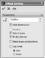
The options available in the Offset Entities interface are as follows:
- Add dimensions. Constrains offset sketch entities. Instead of the On-Edge relations, Offset Entities creates an Offset sketch relation that cannot be re-created manually.
- Reverse. Changes the direction of the offset.
- Select chain. Selects continuous end-to-end sketch entities.
- Bi-directional. Offsets to both sides simultaneously.
- Make base construction. If you are offsetting sketch entities within the active sketch, this option converts the original sketch entities to construction sketch geometry.
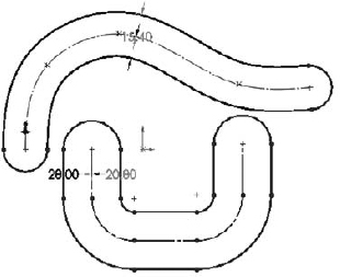
- Cap ends. Is available only when you have selected the Bidirectional option. Capping the ends with arcs is an easy way to create a slot from a sketch of the centerline. This function works with all sketch entities; it is not limited to straight slots. Figure 3.12 shows examples of the Cap ends option.
Caution
The Offset Entities command may fail if the offset distance is greater than the smallest radius of curvature, and you are attempting to offset to the inside of the arc.
In addition to the bidirectional offset with capped ends, SolidWorks also has slot sketch entities for straight and curved slots, which are covered later in this chapter. Composite slots (made of a combination of straight and curved sections) still require the offset method.
FIGURE 3.12 The results of using offset entities cap ends
![]() The Trim is actually several functions rolled into one, and it is an extremely powerful tool for editing sketches. Trim Entities allows several methods for trimming, as well as extending and deleting sketch entities. Figure 3.13 shows the PropertyManager interface for this function.
The Trim is actually several functions rolled into one, and it is an extremely powerful tool for editing sketches. Trim Entities allows several methods for trimming, as well as extending and deleting sketch entities. Figure 3.13 shows the PropertyManager interface for this function.
FIGURE 3.13 The Trim interface

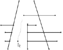
- Power trim. Trims by dragging a cursor trail over multiple entities. The entities that you drag the cursor over are trimmed back to the next intersecting sketch entity. Each time you trim an entity, a red box remains until you trim the next entity. If you backtrack with the cursor and touch the red box, this trim is undone. This option is best used when you need to trim a large number of entities that are easy to hit with a moving cursor. Figure 3.14 shows the Power Trim feature in action.
You can also use power trim to extend sketch entities along their paths by dragging the endpoints. Regular dragging can also change the position or orientation of the rest of the entity, but by using the Power trim feature you affect only the length.
FIGURE 3.14 The Power trim feature in action
- Corner. Trims or extends two selected entities to their next intersection. When you use the Corner option to trim, the selected portion of the sketch entities is kept, and anything on the other side of the corner is discarded. Figure 3.15 shows two ways that the Corner option can work.
FIGURE 3.15 Using the Corner option

- Trim away inside. Trims away selected entities inside a selected boundary. The boundary may consist of a pair of sketch entities or a model face (edges of the face are used as the boundary). Only entities that cross both selected boundaries (or cross the closed loop of the face boundary twice) can be trimmed. This option does not trim a closed loop such as a circle, ellipse, or closed spline.
- Trim away outside. Functions exactly like the Trim away inside option, except that sketch entities outside of the boundary are discarded. The Trim away inside and Trim away outside options are illustrated in Figure 3.16.
FIGURE 3.16 Using the Trim away inside and Trim away outside options

- Trim to closest. This is the default setting. Clicking a sketch entity will:
- Trim it back to the next entity if there is only one crossing entity
- Trim between two crossing entities if there is more than one
- Delete the entity if there are no crossing entities
In all cases, the selected section of the entity is removed. The Trim to closest option can also extend when you drag one entity to another; if an intersection is possible, the first entity is extended to the second entity. Figure 3.17 illustrates how the Trim to closest option functions.
FIGURE 3.17 Using Trim to closest to extend

![]() The Construction Geometry toggles between regular sketch entities and construction entities. Construction sketch entities are not used to create solid or surface faces directly; they are only used for reference — for example, revolve centerlines, extrude and pattern directions, and so forth. Be careful with the icon for this function, because it looks almost identical to the No Solve Move icon, especially as printed here in gray scale.
The Construction Geometry toggles between regular sketch entities and construction entities. Construction sketch entities are not used to create solid or surface faces directly; they are only used for reference — for example, revolve centerlines, extrude and pattern directions, and so forth. Be careful with the icon for this function, because it looks almost identical to the No Solve Move icon, especially as printed here in gray scale.
Note
The icons for Hide/Show Edges, No Solve Move, and Construction Geometry look substantially similar, and in this black and white book they may be indistinguishable.
![]() The Stretch sketch tool is intended for use in sketches where there are enough dimensions to make a particular change difficult by changing dimensions only. It is similar in purpose and use to the AutoCAD Stretch function because it was loosely modeled after the AutoCAD functionality. Stretch enables you to specify a change that will change several dimensions simultaneously. Figure 3.18 shows the initial, intermediate, and final states of the sketch being stretched.
The Stretch sketch tool is intended for use in sketches where there are enough dimensions to make a particular change difficult by changing dimensions only. It is similar in purpose and use to the AutoCAD Stretch function because it was loosely modeled after the AutoCAD functionality. Stretch enables you to specify a change that will change several dimensions simultaneously. Figure 3.18 shows the initial, intermediate, and final states of the sketch being stretched.
FIGURE 3.18 Using the Stretch sketch tool

Tip
The main ideas to remember with the Stretch tool are that it is used to stretch dimensioned lines, and that you need to select the lines that will lengthen or shorten as well as the lines that will move. Because of this, selecting entities for Stretch is best done with the right-to-left window selection, which also selects any items that the selection box crosses. (Left-to-right window selection only selects items that are completely within the selection box.)
Caution
Figure 3.18 shows the X/Y option being used, but if you use the From/To option, be aware that it may unexpectedly delete some sketch relations.
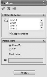
![]() The Move, Rotate, Copy, and Scale sketch tools operate on selections within a sketch. You can use these tools with pre- or post-selection methods. These tools delete existing sketch relations when necessary to accomplish the task. For example, if you want to move a rectangle connected to the origin, the Move tool will delete the Coincident relation between the sketch endpoint and the origin. If you want to rotate a rectangle, the Rotate tool will delete all the horizontal and vertical relations on the entities being rotated. This operation may result in a completely underdefined sketch. SolidWorks does not warn you that sketch relations are being deleted.
The Move, Rotate, Copy, and Scale sketch tools operate on selections within a sketch. You can use these tools with pre- or post-selection methods. These tools delete existing sketch relations when necessary to accomplish the task. For example, if you want to move a rectangle connected to the origin, the Move tool will delete the Coincident relation between the sketch endpoint and the origin. If you want to rotate a rectangle, the Rotate tool will delete all the horizontal and vertical relations on the entities being rotated. This operation may result in a completely underdefined sketch. SolidWorks does not warn you that sketch relations are being deleted.
If you use the Scale tool on a fully defined sketch, SolidWorks will scale the position of the selected entities, deleting sketch relations if necessary to do so, but no dimensions will be scaled or deleted.
Caution
Be careful when using these sketch tools. They can delete sketch relations without warning.
These sketch tools were originally put in the software to avoid some of the complexities and limitations of the Modify Sketch tool, which can also move, copy, rotate, and scale sketches. Figure 3.19 shows the simple interface for the Move Entities command. Select the entities to move in the upper box and the method to move them below.
FIGURE 3.19 The Move Entities interface
![]() Select is usually used to turn off the previous command and return the cursor to its default state.
Select is usually used to turn off the previous command and return the cursor to its default state.
![]() Grid/Snap is used to open the Grid/Snap section of Tools
Grid/Snap is used to open the Grid/Snap section of Tools ![]() Options
Options ![]() Document Properties.
Document Properties.
![]() Parallelogram is used to draw a parallelogram (adjacent sides are not perpendicular, and opposite sides are parallel). Click one corner of the parallelogram, then click the second and third corners. Works like the 3 Point Rectangle except that adjacent sides are not perpendicular.
Parallelogram is used to draw a parallelogram (adjacent sides are not perpendicular, and opposite sides are parallel). Click one corner of the parallelogram, then click the second and third corners. Works like the 3 Point Rectangle except that adjacent sides are not perpendicular.
![]() Polygon creates a regular n-sided polygon in the same way as a circle. Click the center and drag the radius. You need to set the number of sides in the PropertyManager before clicking in the graphics window.
Polygon creates a regular n-sided polygon in the same way as a circle. Click the center and drag the radius. You need to set the number of sides in the PropertyManager before clicking in the graphics window.
![]() Ellipse is created by clicking the center, dragging one axis, and then dragging the other axis.
Ellipse is created by clicking the center, dragging one axis, and then dragging the other axis.
![]() Partial Ellipse is created by clicking the center, dragging one axis, dragging the other axis, and then clicking and dragging the included angle of the partial ellipse. The Partial Ellipse feature works like the Centerpoint Arc command.
Partial Ellipse is created by clicking the center, dragging one axis, dragging the other axis, and then clicking and dragging the included angle of the partial ellipse. The Partial Ellipse feature works like the Centerpoint Arc command.
![]() Parabola is created by clicking the location for the Focus, and then dragging the position of the Apex. You then click and drag the included angle of the parabola, as shown in Figure 3.20. This is a rarely used sketch entity and is often difficult to control with sketch relations or dimensions.
Parabola is created by clicking the location for the Focus, and then dragging the position of the Apex. You then click and drag the included angle of the parabola, as shown in Figure 3.20. This is a rarely used sketch entity and is often difficult to control with sketch relations or dimensions.
FIGURE 3.20 Drawing a parabola

![]() Spline on Surface is used in 3D sketches to draw a freeform spline on any 3D surface. The Spline on Surface feature can cross face boundaries as long as the faces are at least tangent (ideally curvature continuous) across the edge. Spline on Surface can be used to trim surfaces or create split lines.
Spline on Surface is used in 3D sketches to draw a freeform spline on any 3D surface. The Spline on Surface feature can cross face boundaries as long as the faces are at least tangent (ideally curvature continuous) across the edge. Spline on Surface can be used to trim surfaces or create split lines.
![]() Sketch Text creates editable text in sketches using TrueType fonts installed in your Fonts folder. Some fonts produce sketches that are unusable for solid features, due to violating sketch rules with overlapping or zero thickness. You need to be careful which fonts you select, but I have had success with a wide variety of fonts I have found on the Internet. Sketch Text may be dissolved into lines and arcs so that you can edit them manually. Dissolve is available on the RMB menu. Figure 3.21 points out the key elements of the Sketch Text interface.
Sketch Text creates editable text in sketches using TrueType fonts installed in your Fonts folder. Some fonts produce sketches that are unusable for solid features, due to violating sketch rules with overlapping or zero thickness. You need to be careful which fonts you select, but I have had success with a wide variety of fonts I have found on the Internet. Sketch Text may be dissolved into lines and arcs so that you can edit them manually. Dissolve is available on the RMB menu. Figure 3.21 points out the key elements of the Sketch Text interface.
FIGURE 3.21 The Sketch Text interface

Note
Note that the Link To Property icon enables you to link sketch text to a custom property, or a configuration specific custom property. Using configurations and properties to drive sketch text can be a valuable function.
![]() Intersection Curve, in 2D sketches, creates sketch entities where the sketch plane intersects selected faces. In 3D sketches, the Intersection Curve sketch tool creates sketch entities where any types of selected faces intersect. This can be an extremely useful tool in many situations.
Intersection Curve, in 2D sketches, creates sketch entities where the sketch plane intersects selected faces. In 3D sketches, the Intersection Curve sketch tool creates sketch entities where any types of selected faces intersect. This can be an extremely useful tool in many situations.
![]() Face Curves applies the underlying U-V isoparameter mesh to a selected face. It is most commonly used as an evaluation tool for complex surfaces, but you can also use it to create curves to rebuild faces. Accepting the results by clicking OK creates a separate 3D sketch for each spline. Figure 3.22 shows the original surface and the results of using face curves on a complex lofted surface.
Face Curves applies the underlying U-V isoparameter mesh to a selected face. It is most commonly used as an evaluation tool for complex surfaces, but you can also use it to create curves to rebuild faces. Accepting the results by clicking OK creates a separate 3D sketch for each spline. Figure 3.22 shows the original surface and the results of using face curves on a complex lofted surface.
![]() Extend extends a sketch entity up to its next intersection with another sketch entity. This is not to be confused with the Extend for surface entities.
Extend extends a sketch entity up to its next intersection with another sketch entity. This is not to be confused with the Extend for surface entities.
![]() Split Entities splits a sketch entity into two segments. You can also delete it later to rejoin the entity back into a single segment. Closed loop entities require at least two split points.
Split Entities splits a sketch entity into two segments. You can also delete it later to rejoin the entity back into a single segment. Closed loop entities require at least two split points.
![]() Dynamic Mirror can be used when you pre-select a centerline and Dynamic Mirror is turned on. Any new sketch entity that you draw is automatically mirrored to the other side of the centerline. The ends of the mirror line have hatch marks on them to remind you that you have mirroring turned on.
Dynamic Mirror can be used when you pre-select a centerline and Dynamic Mirror is turned on. Any new sketch entity that you draw is automatically mirrored to the other side of the centerline. The ends of the mirror line have hatch marks on them to remind you that you have mirroring turned on.
![]() Linear Pattern creates a one- or two-directional pattern of sketch entities. You can define spacing and angles. Figure 3.23 shows the interface and the results of this function.
Linear Pattern creates a one- or two-directional pattern of sketch entities. You can define spacing and angles. Figure 3.23 shows the interface and the results of this function.
FIGURE 3.22 Using face curves on a complex surface

FIGURE 3.23 The Linear Pattern interface

![]() Circular Sketch Pattern creates a circular pattern of sketch entities.
Circular Sketch Pattern creates a circular pattern of sketch entities.
You should use sketch patterns as little as possible. For many of the same reasons that fillet features are preferred over sketch fillets, pattern features are preferred over sketch patterns. Sketch patterns are not as editable or as flexible as feature patterns. They solve slowly, especially when you pattern many entities. Best practice is to avoid sketch patterns unless there is no alternative.
![]() Make Path is intended to help create machine-design motion in sketches, in particular, cam type motion. Although it is helpful, you do not need to make a block of the cam first. You can then right-click the block and select Make Path. A tangent relation to a path enables a follower to roll around the entire perimeter.
Make Path is intended to help create machine-design motion in sketches, in particular, cam type motion. Although it is helpful, you do not need to make a block of the cam first. You can then right-click the block and select Make Path. A tangent relation to a path enables a follower to roll around the entire perimeter.
![]() Modify Sketch is one of my favorite sketch tools, but it has been falling out of favor in more recent versions of SolidWorks because of the improvements to tools such as Move Sketch. It is also one of few remaining dialog box interfaces in the software. The Modify Sketch tool is flexible and powerful, and enables you to move, rotate, and scale the sketch, as well as mirror about a horizontal or vertical axis or about both axes simultaneously. Figure 3.24 shows the interface, which consists of a dialog box, a special Origin-like symbol, and a context-sensitive cursor.
Modify Sketch is one of my favorite sketch tools, but it has been falling out of favor in more recent versions of SolidWorks because of the improvements to tools such as Move Sketch. It is also one of few remaining dialog box interfaces in the software. The Modify Sketch tool is flexible and powerful, and enables you to move, rotate, and scale the sketch, as well as mirror about a horizontal or vertical axis or about both axes simultaneously. Figure 3.24 shows the interface, which consists of a dialog box, a special Origin-like symbol, and a context-sensitive cursor.
FIGURE 3.24 The Modify Sketch interface
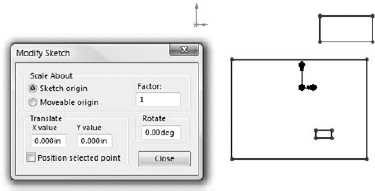
Both the left and right mouse buttons have special functions, which change when the cursor is moved over the three knots on the special Modify Sketch Origin. The RMB enables you to mirror or rotate the sketch, and the left mouse button (LMB) enables you to move the Origin or move the sketch.
This function has some limitations when you use it with sketches that have external relations. Certain functions may be disabled or a warning message may appear, saying that you need to remove external relations to get a particular function to work correctly.
![]() No Solve Move enables the moving of sketch entities without solving any relations in the sketch. If you select this option and you move an entity with relations that would otherwise not allow it to move (such as a collinear relation), you are prompted with a choice to delete the existing relation and continue or copy the entity without the relation. As mentioned earlier, be careful with the icon for this function because it looks almost identical to the Construction Geometry icon, especially as printed here in gray scale.
No Solve Move enables the moving of sketch entities without solving any relations in the sketch. If you select this option and you move an entity with relations that would otherwise not allow it to move (such as a collinear relation), you are prompted with a choice to delete the existing relation and continue or copy the entity without the relation. As mentioned earlier, be careful with the icon for this function because it looks almost identical to the Construction Geometry icon, especially as printed here in gray scale.
![]() Sketch Picture is a picture that is placed in the sketch, lies on the sketch plane, and is listed in the FeatureManager indented under the sketch. The Sketch Picture may be suppressed independently from the rest of the sketch, and when the sketch is hidden the picture is not visible. You can easily move, resize, and rotate Sketch Pictures, as well as apply a transparent background color to them. Sketch Pictures are usually used for tracing over or as a planar decal without the need for PhotoWorks. Figure 3.25 shows the controls for manipulating the Sketch Picture feature.
Sketch Picture is a picture that is placed in the sketch, lies on the sketch plane, and is listed in the FeatureManager indented under the sketch. The Sketch Picture may be suppressed independently from the rest of the sketch, and when the sketch is hidden the picture is not visible. You can easily move, resize, and rotate Sketch Pictures, as well as apply a transparent background color to them. Sketch Pictures are usually used for tracing over or as a planar decal without the need for PhotoWorks. Figure 3.25 shows the controls for manipulating the Sketch Picture feature.
FIGURE 3.25 The Sketch Picture interface

![]() Equation Driven Curve is a sketch spline driven by either an explicit or parametric equation, as shown in Figure 3.26. An explicit equation is in the form y = f(x), while a parametric equation uses multiple equations driven by a common parameter value of the form, such as
Equation Driven Curve is a sketch spline driven by either an explicit or parametric equation, as shown in Figure 3.26. An explicit equation is in the form y = f(x), while a parametric equation uses multiple equations driven by a common parameter value of the form, such as
x = cos(t)
y = sin(t)
0>t>pi
where t is a number in radians.
The result is a proportional spline in a sketch, not a curve feature as the name suggests. The capability exists to drag the spline itself, or its endpoints, in 2D or 3D and SolidWorks calculates the new transformation. To reposition a sketch, use sketch relations and dimensions.
If you start an Equation Driven Curve in a 2D sketch, you get the form for a 2D curve equation. If you start in a 3D sketch, you get the form for a 3D curve. Once these splines are created, you cannot remove the relation to the equation and manually edit the spline; they are tied to the equation until you delete the entire spline.
One way to get around this limitation would be to create an equation-driven curve in one sketch, and then open another sketch and use convert entities to copy the spline, delete the On Edge relation, and use Simplify Spline to add control points to it. This is a technique commonly used with other types of curves; it does not enable you to update the overall size or shape of the spline through the equation, but you can manually adjust sections of a curve originally created from equations. Examples of where this might be useful would be a lead in or lead out on a cut thread, a special attachment loop in the middle of a spring, or a flare around the edge of a lens or reflector dish for mounting.
FIGURE 3.26 The Equation Driven Curve PropertyManager

![]() Straight Slotand Curved Slot draw slots of a given width and length with full rounds on the ends. All the slot sketch entities can be seen in the PropertyManager shown in Figure 3.27. If you need to draw a composite slot or a slot with multiple entities, you will need to use the bi-directional sketch offset with capped ends mentioned earlier.
Straight Slotand Curved Slot draw slots of a given width and length with full rounds on the ends. All the slot sketch entities can be seen in the PropertyManager shown in Figure 3.27. If you need to draw a composite slot or a slot with multiple entities, you will need to use the bi-directional sketch offset with capped ends mentioned earlier.
FIGURE 3.27 The PropertyManager for the slot sketch entities

Using the Dimensions/Relations toolbar
The Dimensions/Relations toolbar has a few tools that you have already seen, but as the name suggests, it also contains tools that will either help you to create or investigate dimensions and sketch relations. Figure 3.28 shows the default toolbar, but in the following pages, you look at all the available tools you can see at Tools ![]() Customize
Customize ![]() Commands
Commands ![]() Dimensions/Relations.
Dimensions/Relations.
FIGURE 3.28 The Dimensions/Relations toolbar
![]()
 Smart Dimension. Lets you dimension the sketch entity and combines several dimensioning methods into a single tool, such as horizontal, vertical, aligned, radial, diameter, and so on.
 Horizontal Dimension. Applies a dimension to a sketch entity that drives the horizontal distance between the endpoints.
 Vertical Dimension. Works like a horizontal dimension but vertically.
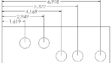
 Baseline Dimensions. Creates dimensions only in drawing documents. Baseline Dimensions are different from most of the dimension tools that you find on the Dimensions/Relations toolbar in that they can create driven dimensions on view geometry or driving dimensions on sketch geometry in a drawing, but cannot be used on sketch geometry in parts. Baseline Dimensions start from a single reference; then as you select additional references, additional dimensions are stacked (see Figure 3.29).
FIGURE 3.29 Baseline Dimensions on a drawing
 Ordinate Dimensions. Drives dimensions where a set of ordinate dimensions originate from a common zero point. To use these dimensions, simply click a zero location, place the zero dimension, and then click additional points. The dimensions are placed and are automatically aligned to the rest of the dimensions.
If a line is not selected as the zero reference entity, the Ordinate Dimension feature defaults to a Horizontal Ordinate.
You can remove Ordinate Dimensions from the common alignment by right-clicking the dimension and selecting Break Alignment. Ordinate Dimensions will jog automatically if SolidWorks senses that the dimensions are getting too close to one another. You can also jog them manually. After you create the Ordinate Dimension set, you can add to it by accessing the Add to Ordinate command through the RMB menu. All the options for Ordinate Dimensions are shown in Figure 3.30.
Not all the listed options are available in the model sketch environment; some are available only in drawings.
![]() Horizontal and Vertical Ordinate Dimensions have the same function as the regular Ordinate Dimensions, except that they only drive horizontal and vertical dimensions, respectively.
Horizontal and Vertical Ordinate Dimensions have the same function as the regular Ordinate Dimensions, except that they only drive horizontal and vertical dimensions, respectively.
![]() Chamfer Dimension is another type of dimension that is only driven and only applied in drawing documents. It works by first selecting the chamfered edge and then selecting the angle reference edge. It produces dimensions like the one shown in Figure 3.31.
Chamfer Dimension is another type of dimension that is only driven and only applied in drawing documents. It works by first selecting the chamfered edge and then selecting the angle reference edge. It produces dimensions like the one shown in Figure 3.31.
FIGURE 3.30 Options for Ordinate Dimensions

FIGURE 3.31 Applying a chamfer dimension

![]() Automatic Relations toggles to enable or disable the automatic creation of sketch relations while sketching. This toggle is also available through Tools
Automatic Relations toggles to enable or disable the automatic creation of sketch relations while sketching. This toggle is also available through Tools ![]() Sketch Settings
Sketch Settings ![]() Automatic Relations. Automatic relations help you to create intelligent sketches with less manual intervention. Although using them takes a little practice, it is well worth the effort.
Automatic Relations. Automatic relations help you to create intelligent sketches with less manual intervention. Although using them takes a little practice, it is well worth the effort.
Caution
As with any automatic function, there are times when automatic relations will do things that you do not expect or want. While you are sketching, it is recommended that you watch the cursor and the relations that it automatically applies.
While sketching, symbols appear on the cursor to show that a relation will automatically be created. These symbols have a yellow background and will apply horizontal, vertical, coincident, tangent, parallel, and perpendicular relations. Figure 3.32 shows two situations where automatic relations are applied — a horizontal and a tangent relation.
FIGURE 3.32 Some automatic relations that appear on the cursor

Inferencing in Sketch
Although SolidWorks users (even experienced ones) often confuse Inferencing and Automatic Relations, these functions are not the same. Inferencing refers to the blue dotted lines that display in Sketch mode when the cursor aligns with endpoints, centerpoints, or the Origin. Inferencing does not create sketch relations, with one exception. If both ends of a line pick up the same inference to the same point, SolidWorks will add that inference as an automatic relation.
When the cursor displays a small sketch relation symbol with a yellow background, this means that an automatic relation is going to be applied. If the relation symbol has a white background, the relation is inferenced but not applied as an actual sketch relation. The symbols with the blue (the color may also be green in SolidWorks 2008 or later) background are relations that have been applied to existing sketch entities. The symbols look the same, regardless of background color. Be aware that differences in versions and differences in color schemes can cause these colors to be different on your system.
Table 3.1 shows the symbols for the various inferences, automatic relation cursors, and applied sketch relations. The difference between the three types is simply the background colors: white, yellow, and blue, respectively.

The Fully Define Sketch interface uses sketch relations and dimensions to fully define the active sketch. It enables you to select which types of sketch relations and dimensions will be used to do this. Figure 3.33 shows the Fully Define Sketch interface. Be careful of this icon because it looks almost identical to the Sketch icon.
If you are familiar with older versions, the Fully Define Sketch function was formerly called Auto Dimension and has absorbed the functionality of Scan Equal and Add Relations. This function is very useful when used with imported sketch data. If you do not like the automatic dimensioning scheme, you can at least take advantage of the automatic sketch relations.
Best Practice
The Fully Define Sketch function does not necessarily use the best dimensioning practice for manufacturing drawings or for Design Intent. This tool is best used in situations when baseline and ordinate dimensions are appropriate.
FIGURE 3.33 The Fully Define Sketch interface

Exploring Sketch Settings
In addition to sketch tools, another important aspect of controlling sketches is sketch settings. Sketch settings are found in two different locations. The first location is at Tools ![]() Options
Options ![]() Sketch. In this chapter, I cover the settings found at the second location, Tools
Sketch. In this chapter, I cover the settings found at the second location, Tools ![]() Sketch Settings. These settings mainly affect sketch relations.
Sketch Settings. These settings mainly affect sketch relations.
- Automatic Solve is turned on by default. As you make changes to a sketch by adding relations or changing dimensions, SolidWorks automatically and immediately updates the sketch to reflect the changes. When the Automatic Solve setting is turned off, these changes are deferred until you exit the sketch or turn the Automatic Solve setting back on. The setting can be useful to prevent intermediate solutions (for example, when half of the changes are made) that may cause problems with the sketch, and when you are confident that the outcome will be correct. It is a rarely used option, and you could probably exist just fine without even knowing this option was there at all.
If you import a large drawing from the DXF or DWG format, these drawings import as sketch entities into either a SolidWorks sketch or a drawing. SolidWorks may automatically turn off the Automatic Solve setting for performance (speed) reasons on files of this type.
- Enable Snapping is turned on by default. It enables the cursor to snap to the endpoints of existing sketch entities to help you make cleaner sketches. When you turn this setting off, Automatic Relations is also disabled (although the icon for the setting remains depressed, Automatic Relations are not created). Holding down the Ctrl key while sketching disables snapping. Holding down the Ctrl key while dragging sketch entities functions like copying sketch geometry. The No Solve Move is discussed in the Sketch toolbar section.
- Detach Segment on Drag is turned off by default. When you turn this setting on, the Detach Segment on Drag feature enables you to pull a single sketch element away from a chain of elements. For example, if you had a rectangle and you wanted to detach one of the lines from the rest of the rectangle without using this setting, you would have to draw extra geometry and then trim and delete lines in order to release the endpoints.
It is recommended that you leave Detach Segment on Drag off. Turn it on only when you need it, and then immediately turn it off again. This setting can be hazardous for everyday use, because it enables you to simply drag sketch elements that may be otherwise fully defined.
- Override Dims on Drag is off by default. When you turn this setting on, it enables you to drag fully defined sketch geometry, and the dimensions will update to match the dragged size. This is another setting that you should use sparingly. It can be useful for doing concept work, but you should leave it off when working with production data for obvious reasons.
Note
Combining Override Dims on Drag with Instant3D can be very handy for concept work, enabling you to drag sketches, model faces, and edges easily.
Using Sketch Blocks
Sketch blocks are collections of sketch entities that can be treated as a single entity and can be reused within a single document or shared between documents. You can use sketch blocks in parts, assemblies, and drawings. To create a sketch block, select a group of sketch entities and click the Make Block button on the Blocks toolbar, or select Tools ![]() Blocks
Blocks ![]() Make. Pre-selection is not necessary; you can also select the entities after you invoke the command.
Make. Pre-selection is not necessary; you can also select the entities after you invoke the command.
Blocks may be internal to a particular document, or they may be saved as an external file. The externally saved block may be linked to each document where it is used, so that if the block is changed, it updates in the documents where it is used.
You can use blocks in conjunction with the Make Path function mentioned earlier in this chapter to create functional layouts for mechanisms. You can also use blocks in an assembly to build parts in-context. Refer to the SolidWork 2011 Assemblies Bible (Wiley, 2011) for a more in-depth examination of the assemblies aspects of blocks in SolidWorks.
The following is a description of the various tools that are available on the Blocks toolbar:
 Make Block. Creates a sketch block from selected sketch entities. You can position a manipulator to denote the insertion point for the block. Blocks may attach at any entity endpoint, but the insertion point follows the cursor.
 Edit Block. Enables you to edit an existing block as if it were a regular sketch.
 Insert Block. Enables you to select from a list of open blocks or browse to a location where blocks are stored. You can edit the insertion point by using the Edit Block function.
 Add/Remove. Enables you to add or remove sketch entities from the block without deleting them from the sketch while editing a block.
 Rebuild Block. Allows changes to a block to be reflected in any external relations without exiting the block. For example, if you have a block in a sketch and a sketch line is coincident to one of the endpoints in the block, you may edit the block such that the referenced endpoint moves. As a result, the line in the sketch will not move until you exit the block or use the Rebuild Block function.
 Save Block/Save Sketch As Block. Saves a selected block to an external file (with the *.sldblk extension) or saves the selected sketch as a block.
 Explode Block. Removes all the sketch entities from a block and brings them into the current sketch.
 Belt/Chain. Enables you to make a belt or chain around a set of pulleys. Each pulley must be a block. After activating the command (by right-clicking on a sketch or block), you can select each pulley and use the arrow on the pulley to switch the side of the pulley to which the belt goes. You can also compensate for the thickness of the belt (this is important when both sides of the belt are in contact with pulleys) and drive the pulley arrangement using the length of the belt. Figure 3.34 shows the Belt/Chain dialog box.
FIGURE 3.34 The Belt/Chain dialog box

Working with Reference Geometry
Reference geometry in SolidWorks is used to help establish locations for geometry that you can't physically touch, such as planes, axes, coordinate systems, and points. You often use reference geometry to establish a characteristic of the finished solid model before the model is created or to include an item that you may want to mate another part to in an assembly later. Mate References are also classified as Reference Geometry.
The importance of working with reference geometry becomes obvious in situations where you need to create geometry that doesn't line up with the standard planes. You might use planes to represent faces and axes to represent the centers of holes. Axes are often used to establish a direction, such as in plastic parts where, because of draft, you never truly have any vertical edges; an axis is frequently used to establish the direction of pull for the mold.
Coordinate systems come in handy, especially when translating a part from one system to another for the purpose of machining or some type of analysis. SolidWorks users usually model in such a way that the modeling work is made simpler by the choice of how the part origin is positioned relative to features of the part, but rapid prototyping, machining, mold building, and sheet metal manufacturing applications may have different requirements. As a part modeler, you cannot account for the needs of all downstream applications with your initial choice of origin placement, but you can always create a reference coordinate system for those downstream applications to use.
Creating planes
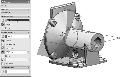
![]() Planes are the most commonly used type of reference geometry because they are used for sketching, cutting, as extrude end conditions, and more. The Plane feature PropertyManager and its functionality have changed significantly in recent versions. With the new interface, shown in Figure 3.35, you start by selecting model items (faces, edges, points, vertices, or other sketch or reference geometry) that you want to use to create the plane. The new plane uses constraints like sketch relations from the selected references. For example, in Figure 3.35, the new plane is tangent to the selected First Reference cylindrical face and at an angle to the selected Second Reference of a plane.
Planes are the most commonly used type of reference geometry because they are used for sketching, cutting, as extrude end conditions, and more. The Plane feature PropertyManager and its functionality have changed significantly in recent versions. With the new interface, shown in Figure 3.35, you start by selecting model items (faces, edges, points, vertices, or other sketch or reference geometry) that you want to use to create the plane. The new plane uses constraints like sketch relations from the selected references. For example, in Figure 3.35, the new plane is tangent to the selected First Reference cylindrical face and at an angle to the selected Second Reference of a plane.
FIGURE 3.35 Creating a new plane from a set of selections and constraints
The good news about this method is that there are far more options for creating planes than in the previous method, but the bad news is that the options are not all spelled out anywhere. You have to make a selection before it shows you the available constraints. The older interface presented the available options right up front, but there were fewer to choose from. Hopefully this interface matures in the future. Meanwhile, you may need to experiment to see what works best for the type of modeling you do.
For longtime users, when you start using the new Plane functionality, it may be best to try to ignore the new interface and simply make the same types of selections that you made in the past. The new Plane functionality will work perfectly that way. If you are a new user, just think of how you would like to specify the new plane, given the available geometry, and give it a try. The available options are not documented, so working with this interface requires some blind trust on the part of the user. The tool is quite powerful, but you will need to spend time experimenting with it. Even then, you will be unsure whether you are missing important options.
Working with axes
![]() You can use axes to create pivot points in a part where you do not have any hole-type geometry for mating with other parts, or as a direction of pull for plastic parts or molds. Axes are frequently used to establish direction. Figure 3.36 shows that the first three features in a plastic part are axes established from the standard planes.
You can use axes to create pivot points in a part where you do not have any hole-type geometry for mating with other parts, or as a direction of pull for plastic parts or molds. Axes are frequently used to establish direction. Figure 3.36 shows that the first three features in a plastic part are axes established from the standard planes.
FIGURE 3.36 Using axes to establish direction

Consider using axes set up in this way as standard features in your template files. They can be effective in assemblies for moving parts in orthogonal directions and in parts for pattern or draft directions.
Note
The interface for the Axis feature has not been changed to match the Plane interface. Notice that the methods for creating an axis are spelled out clearly in the interface. I expect to eventually see a change to Axis to make it match the Plane interface.
Using Coordinate Systems
![]() Coordinate Systems in SolidWorks are primarily used for import and export, but can also be used for mating, mass properties, and other purposes. Coordinate Systems are usually located by a point to determine location or a set of edges to determine direction. Figure 3.37 shows the PropertyManager for assigning a coordinate system, along with the Export Options dialog box, which you can access from the Save As dialog box when the Files of Type drop-down is set to an export format.
Coordinate Systems in SolidWorks are primarily used for import and export, but can also be used for mating, mass properties, and other purposes. Coordinate Systems are usually located by a point to determine location or a set of edges to determine direction. Figure 3.37 shows the PropertyManager for assigning a coordinate system, along with the Export Options dialog box, which you can access from the Save As dialog box when the Files of Type drop-down is set to an export format.
FIGURE 3.37 Use Coordinate Systems to export parts and assemblies with a new origin location.

To use the coordinate system when saving as a translated file type such as IGES or Parasolid, click the Options button, as shown in Figure 3.37; at the bottom of the Export Options dialog box, a selection box for Output coordinate system appears.
To use the coordinate system with mass properties, choose Tools ![]() Mass Properties from the menu, and then select the Output coordinate system, as shown in Figure 3.38.
Mass Properties from the menu, and then select the Output coordinate system, as shown in Figure 3.38.
FIGURE 3.38 Assigning the coordinate system with a well-hidden setting

Using points as reference geometry
![]() The Point reference geometry feature is infrequently used; however, in some situations there is nothing else that does the job quite as well. This is not the same as a sketch point and does not require a sketch to be open; it is just a reference point that you can place in space. Figure 3.39 shows the PropertyManager for the Point reference geometry feature.
The Point reference geometry feature is infrequently used; however, in some situations there is nothing else that does the job quite as well. This is not the same as a sketch point and does not require a sketch to be open; it is just a reference point that you can place in space. Figure 3.39 shows the PropertyManager for the Point reference geometry feature.
FIGURE 3.39 The Point reference geometry feature has several modes of point creation you won't find elsewhere.

My favorite Point placement method is the Along Curve Distance option (the bottom one in Figure 3.39). It enables you to create several regularly spaced points along a curve.
Tutorial: Learning to Use Sketch Relations
Although, it is useful to read through the definitions and functions of all the sketch entities, tools, and relations, using your mouse to create is what this is all about. This tutorial makes sure that you get to know all the major functions in SolidWorks sketches. Almost every part that you build will start with a sketch, so this is a skill worth mastering. Follow these steps to learn about sketch relations:
On the DVD
The BibleInchTemplate.prtdot template used in this tutorial is in the Chapter 3 folder on the DVD.
- Open a new part using a template that you set up in the Template tutorial from Chapter 1. If you do not have this template, there is one provided for you on the DVD named BibleInchTemplate.prtdot. Copy it to your templates folder and use it to create a new part. You may also use a SolidWorks default template.
- Select the Front plane in the FeatureManager, and click the Sketch button on the Sketch toolbar. Click the Line tool from the Sketch toolbar.
- Move the cursor near the Origin; the yellow Coincident symbol appears.
- Draw a line horizontal from the Origin. Remember that there are two ways to sketch the line: Click+click or click and drag. Make sure that the line snaps to the horizontal and that there is a yellow Horizontal relation symbol. The PropertyManager for the line should show that the line has a Horizontal relation. Also notice that the line is black, but the free endpoint is blue (after you hit Esc twice to clear the tool, then clear the selection). This means that the line is fully defined except for its length. You can test this by dragging the blue endpoint.
- Click the Smart Dimension tool on the Sketch toolbar, use it to click the line that you just drew, and place the dimension. If you are prompted for a dimension, type 1.000. If not, then double-click the dimension; the Modify dialog box appears, enabling you to change the dimension. The setting to prompt for a dimension is found at Tools Options General, Input Dimension Value.
- Draw two more lines to create a right triangle to look like Figure 3.40. If the sketch relations symbols do not show in the display, turn them on by clicking View Sketch Relations. You may want to set up a hotkey for this, because having sketch relations is useful, but often gets in the way. Note that the sketch relation symbols may also be green, depending on how your software is installed.
FIGURE 3.40 Draw a right triangle.
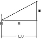
- Drag the blue endpoint of the triangle. Dragging endpoints is the most direct way to change the geometry. Dragging the line directly may also work, but this sometimes produces odd results. The sketch leaves a ghost when dragging so that you can see where you started. Note that the setting for leaving a ghost when dragging a sketch is found at Tools Options Sketch, Ghost Image On Drag.
- Click the Smart Dimension tool, and then click the horizontal line and the angled line. This produces an angle dimension. Place the angle dimension and give it a value of 30°.
- Click the Sketch Fillet tool, set the radius value to 0.10 inches, and click each of the three endpoints. Where the 1.000-inch dimension connects to the sketch, SolidWorks has created virtual sharps. Figure 3.41 shows the sketch at this point. You may now want to turn off the Sketch Relations display because the screen is getting pretty busy. You can find this setting at View Sketch Relations.
FIGURE 3.41 The resulting sketch after you perform Step 9
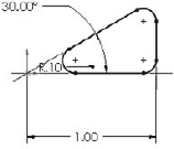
- Draw a line starting from the midpoint of the angled line. The midpoint should highlight when you move the cursor close to it. Draw the line perpendicular to the angled line. A dotted yellow line appears, showing where the perpendicular lies. When you follow this line, the yellow perpendicular symbol appears on the cursor. Make this line approximately .25 inches long. Feedback on the cursor also shows the length of the line as you draw it.
- Draw two more lines ending at the endpoint of the sketch fillet, as shown in Figure 3.42. Use the Inferencing lines to line up the second angled line with the end of the arc.
- Click the Trim tool from the Sketch toolbar. Make sure that the Trim option is set to Closest. Click the angled line of the triangle between the two lines sketched in Step 11. This trims out that section and makes the sketch a single closed loop. A warning may appear because you have a Midpoint relation to the line being trimmed; you no longer want this relation, but you want the lines to intersect at their endpoints. Select Yes at the prompt.
- Click the Smart Dimension tool. Use it to create aligned dimensions on the short line (.25 inches) and one of the long lines (.125 inches). You may now want to reorganize some of the dimensions if the display is becoming crowded.
- At this point, two of the lines should be blue, but it may not be clear why they are not defined. Select one of the blue lines and drag it. Notice that what changes is the arc nearest the Origin. This changes in a way that is not useful for this part. To lock this line where it needs to be, select the blue line nearest the Origin and the centerpoint of the arc nearest the Origin, and give them a Coincident relation in the PropertyManager. The result is a fully defined sketch, as shown in Figure 3.43.
FIGURE 3.42 The resulting sketch after you perform Step 11
FIGURE 3.43 The resulting sketch after you perform Step 14

- Save the part with the name Sketch Relations Tutorial.sldprt. Close the part.

Tutorial: Using Blocks and Belts
Sometimes I am amazed at the things that can be done in SolidWorks, even with fairly simple tools. This is one of those times. If you design machines, this tutorial will have some extra meaning for you. If you do not design machines, Blocks and Belts are still valuable tools to have in your toolbox ready to use in various situations. Follow these steps to learn about using Blocks and Belts.
- Open a new part with inches as the units.
- Draw a sketch on the Front plane as shown in Figure 3.44, with four lines connected to the Origin. Exit the sketch and rename it Layout Sketch, either by clicking twice on the name of the feature in the FeatureManager or by selecting it and pressing F2.
- Open a second sketch on the Front plane, and draw a circle centered on the Origin with a 6-inch diameter.
- Inside the circle, draw a Centerpoint rectangle centered on the Origin.
- Select two adjacent sides of the rectangle and make an Equal sketch relation between them. (This makes the rectangle into a square.)
- Click the Smart Dimension tool, and apply a 1.000-inch dimension to one side of the square. Turn off the Smart Dimension tool by clicking it again on the toolbar or pressing Esc.
- If the Blocks toolbar is not active, activate it and then select Make Block. You can also access this command through Tools Block Make.
- Window select the circle and the square by clicking and dragging a box that includes all the items in the sketch. The PropertyManager to the left displays a circle and six lines that are to be made into a block.
- Expand the Insertion Point panel in the PropertyManager. This causes a blue manipulator Origin to appear in the graphics window. Click this Origin and drag it onto the center of the circle. Then click the green check mark icon to exit the Make Block dialog box. This is shown in Figure 3.45.
.
- The items in the block now turn gray. Click anywhere on the block and drag it out of the way. Then drag the center of the circle and drop it on the part Origin.
- Click the Insert Block tool on the Blocks toolbar. Place the block on the opposite sharp corner of the layout sketch.
- Create another block that is identical to the first one, except that it has a diameter of 3 inches instead of 6 inches. You can do this by selecting the first block, clicking Edit Block from the toolbar, and copying (Window select and Ctrl+C). Then exit the Edit Block and paste (Ctrl+V) in the regular sketch. Make sure to also change the insertion point for this second block to the center of the circle.
- Insert a second instance of this second block, and make sure that both of them have the center of the circle at the two remaining intersection points of the four-sided shape of the layout sketch. At this point, your sketch should look like Figure 3.46.

- Click the Belt/Chain tool on the Blocks toolbar. Select the blocks in counterclockwise order, starting at the Origin. On the last pulley, you will have to click the arrow to get the belt to go the correct way around the pulley. Use Figure 3.47 as a guide.
- Make sure that the Engage Belt option is selected. This enables you to make the pulleys move in the same way that they would in a real belt-driven mechanism.
- Click the Use Belt Thickness option and assign .25 inches for the thickness. The belt should be offset from the pulleys.
- Click the green check mark icon.
- Click and drag one of the corners of the square in a pulley. All the pulleys should turn as if this were a real mechanism. The ratios are also observed because the small pulleys rotate faster than the large ones.
- Save this part as Blocks and Belts Tutorial.sldprt. Exit the part.

FIGURE 3.47 Creating the belt around the pulleys

Tutorial: Creating Reference Geometry
This tutorial steps you through creating reference geometry on an existing part in preparation for locating 3D features.
On the DVD
The Chapter 3 Reference Geometry.SLDPRT file (or drawing) used in this tutorial is in the Chapter 3 folder on the DVD.
- Open the file from the DVD in the Chapter 3 folder called Chapter 3 Reference Geometry - start.sldprt.
 In the FeatureManager filter, type plane1. Double-click Plane1 in the FeatureManager, then double-click the 3.25-inch dimension on the screen and change it to 3.35 inches. Click the rebuild symbol (traffic light) and watch the update. This plane locates the mounting base of the part.
When you are done, click the X at the right end of the FeatureManager filter to clear the result. Pressing Esc does the same thing.
 Click the Axis toolbar button from the Reference Geometry flyout menu (on the Features tab of the CommandManager in a default install).
- Select the inside face of a hole on the part, as shown in Figure 3.48 This creates an axis on the centerline of the hole. You should note that a temporary axis already exists for all cylindrical faces, but making a true axis feature helps this one stand out as different from the other holes on the part.
FIGURE 3.48 Making one hole stand out by creating an axis feature
The selection of the Cylindrical/Conical Face option should be automatically activated by your selection of the cylindrical face of the hole. Accept the result with the green check mark when the selections and settings are complete.
 Click the Plane toolbar button from the Reference Geometry flyout on the Features tab of the CommandManager.
- Select the large cylindrical face of the part as the First Reference and the axis you just created as the Second Reference. Make sure the First Reference uses the Tangent constraint and the Second Reference uses the Coincident constraint. This makes a plane tangent to the main cylinder in the part that goes through the patterned hole, as shown in Figure 3.49.
FIGURE 3.49 Creating a plane from tangent and coincident constraints

 Open a new sketch on the new plane.
 Click the View menu and activate the Temporary Axes option. You should now see blue axes (without names) appear along the centerlines of every conical or cylindrical face on the model (except for faces created by fillet or chamfer features).
Note
If the view is already normal to the selected plane, and you double-click Normal To, the view switches to 180 degrees opposite. For this exercise, it doesn't matter which way you view the part, but from the top is better than from the bottom because the view is clearer.
- Select the sketch plane either from the graphics window or the FeatureManager. Press the Spacebar on the keyboard and double-click Normal To. There are other ways to access this command, but this is the method that will work regardless of your interface setup. You can use whatever method you prefer.
 Use the Centerpoint Rectangle to create a rectangle centered around the temporary axis of the large cylindrical face. Make sure that the centerpoint, which is the first click you make, picks up a coincident automatic relation with the temporary axis. Make sure the second click to place the corner of the rectangle does not pick up any automatic relations.
 You can tell if any relations have been applied if you go to the View menu and activate Sketch Relations. Make sure the centerpoint has a coincident relation and that none of the corners has any relations.
Note
The temporary axis is not on the same plane as the sketch plane, so if the view is not normal to the sketch plane, picking up an automatic relation between the centerpoint of the rectangle and the temporary axis will be difficult.
 Use the Smart Dimension tool to apply dimensions, as shown in Figure 3.50. Note that the 3.450-inch dimension goes to the part origin on the left. You can select this from either the graphics window or the FeatureManager.
Best Practise
It is best practice to dimension or create sketch relations to items that have the fewest other relations. You should try to use the part origin and standard planes when possible. Dimensioning to reference geometry is better than dimensioning to model edges, although this is not always possible. Experienced users will immediately recognize the need for removing layers of references to prevent restrictive parent-child relations and broken or dangling relations. For beginning users, after you have some experience with making changes to models where relations have been applied carelessly, being more selective with sketch and dimension references will look more attractive to you.
 Click the Extrude toolbar button on the Features tab of the CommandManager. Rotate the model (by dragging with the mouse wheel depressed) slightly so you can see the side of the extrusion preview, as shown in Figure 3.51.
FIGURE 3.51 Creating the extrusion from the new sketch

 You may have to adjust the direction of the extrude using the icon with the arrows just below the Direction1 heading in the Boss-Extrude PropertyManager.
- Use the Up To Next end condition, which makes the sketch go up to the next solid that it encounters.
- Use the View menu to turn off the display of Axes, Temporary Axes and Planes.
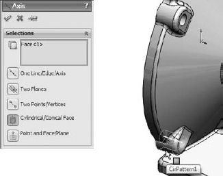

Summary
Sketching in SolidWorks is something that you will do almost every time you open the software. A lot of automated functions are available that can enable you to do much of the work for you. You also have a lot of control to make changes manually. Remember that the best way to create most sketches is to use automatic relations when you can, sketch the approximate shape that you want to make, and then either drag it to pick up automatic relations, add dimensions, or add relations manually. Remember that you can use the left-click context toolbar to speed up adding relations manually.
The options for creating intelligent relationships that establish your Design Intent, as well as SolidWorks's capabilities in laying out mechanisms, is only limited by your imagination. The more familiar you become with the tools in your toolbox, the more of a craftsman you can become with this software.
Reference geometry is an essential part of creating and controlling relationships in any parametric model. Reference geometry is usually more stable than solid geometry, so sketch relations and dimensions should use reference geometry as references when possible.