
CHAPTER 2
Navigating the SolidWorks Interface
IN THIS CHAPTER
Discovering elements of the SolidWorks interface
Customizing the interface to work for you
Exploring the interface
The SolidWorks interface offers a wide range of tools. You will find more than one way to do almost everything. There is no one best way to use the interface; and each method has strengths and weaknesses depending on the task, and depending on the individual.
In this chapter, I will start by displaying the entire default interface, but in the rest of the book I will only show a reduced interface, mainly to save space and keep the focus on the graphics window.
Once you have mastered the various interface elements and customized your SolidWorks installation, working with the software becomes much more efficient and satisfying. You may find your mastery of the interface comes with practice and experience. Many existing users may discover features in this book that they were not aware of, even though they have been trained and have used the software for years.
I explain each interface element identified in Figure 2.1 in detail within this chapter.
You might want to put a bookmarker in this page and refer back to Figure 2.1 often, as much of the interface discussion refers to elements illustrated in this figure.
FIGURE 2.1 Elements of the SolidWorks interface

Identifying Elements of the SolidWorks Interface
The major elements of the SolidWorks interface are the graphics window, where all the action takes place, the FeatureManager, which is the list of all the features in the part, the PropertyManager, where most of the data input happens, and the CommandManager and toolbars, where you access most of the commands in the software.
Figure 2.1 shows the default interface with a couple of exceptions. First, I have pinned the Title Bar menu in place. Second, I have detached the PropertyManager. Throughout the rest of this book, I will use a simplified CommandManager display (without the text on the buttons), and I may use the Sketch toolbar independent from the CommandManager to minimize CommandManager tab switching. I may also deactivate the Heads-up View toolbar to keep the display area clean, and use the whole Right Mouse Button (RMB) menu rather than the default Context Menus at the top of the truncated RMB menu.
Using the CommandManager and toolbars
In some respects, the CommandManager resembles the Microsoft (MS) Ribbon interface found in Office 2007 applications. SolidWorks did not do a strict implementation of the MS Ribbon, because it wanted to add more customizability. A far more complete array of interface configuration possibilities awaits you with SolidWorks 2011. In this section of the chapter, I show you how to make the CommandManager work for you and how to use regular or flyout toolbars to replace it effectively.
Exploring the CommandManager
The CommandManager is an area of the interface that you can use to flip between sets of related commands. It does not necessarily save space, and I don't believe it helps you to work faster. However, it does make your workspace a bit more organized. The main purpose of the CommandManager is to give you easy access to all commands without fumbling with the menus, and even access to customized groups of icons that are not available on a single default toolbar, without cluttering the entire screen with toolbars.
The CommandManager accomplishes this by providing small tabs under the left end of the toolbar area to enable you to switch the collection of tools that appears. Figure 2.2 shows the CommandManager in customize mode, showing all the tabs available in a default setup. To get the CommandManager into customize mode, right-click one of the CommandManager tabs and select Customize CommandManager. Alternatively, you can choose Tools ![]() Customize.
Customize.
Note
To access the pull-down menus in a default setup, place the cursor over the SolidWorks logo or the small flyout triangle to the right of it in the upper-left corner of the SolidWorks window. Figure 2.2 shows the flyout for pull-down menus pinned in place. To keep the menu in that position, click the pushpin on the right end of the flyout menu bar.
FIGURE 2.2 Customizing the CommandManager

Customizing the CommandManager
Notice the last tab along the bottom of the CommandManager on the right. If you want to add another tab, you can right-click this tab and select the tab you want to add. You can also select to add a blank tab and populate it with individual buttons. Figure 2.3 shows a detail of the Add Tab menu options after you right-click the tab.
FIGURE 2.3 Adding tabs to the CommandManager

You can also left-click the special tab on the right and skip the Add Tab menu. To add individual buttons, first find the button you want to add in the Customize dialog box by choosing Tools ![]() Customize. Click the Commands tab in the Customize dialog box, and then switch the CommandManager to the tab you want to add the button to, and drag the button from the Customize dialog box to the CommandManager. You can remove buttons from the CommandManager by dragging them into the blank graphics window area.
Customize. Click the Commands tab in the Customize dialog box, and then switch the CommandManager to the tab you want to add the button to, and drag the button from the Customize dialog box to the CommandManager. You can remove buttons from the CommandManager by dragging them into the blank graphics window area.
Docking the CommandManager
In SolidWorks, you can undock the CommandManager and leave it undocked, pull it to a second monitor, or dock it vertically to the left or right. To undock it, click and drag on any non-toolbar button area of the CommandManager, such as around the border. To re-dock an undocked CommandManager or to change its docking location, drag it onto one of the docking stations around the screen. Figure 2.4 shows the CommandManager undocked.
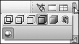
Using Auto Collapse
The small box with the arrows in it in the upper right-hand corner of the undocked CommandManager and the undocked PropertyManager is the Auto Collapse option. There seem to be some inconsistencies in the way this option works with certain undocked PropertyManagers. You may have to resize undocked PropertyManagers manually for various features. When the option is active, the PropertyManager is supposed to expand and collapse automatically and should not require scroll arrows unless the PropertyManager is larger than your monitor's height. In the condition it is shown in Figure 2.4, the undocked CommandManager will not collapse, but if you click Auto Collapse, the arrows go away, and the entire CommandManager acts like a big flyout toolbar. This can be very handy because it saves a lot of space on the screen, but at the same time it requires additional mouse movement to open it up. This is the common trade-off in this interface — you can trade screen space for additional mouse movement or clicks.
FIGURE 2.4 The undocked CommandManager without text labels

Mixing the CommandManager with toolbars
To put a toolbar inline with the CommandManager, drag the toolbar close to the right-hand end of the CommandManager. A space on that row or column will open up. The amount of space that opens up depends on the CommandManager tab with the longest set of icons, even if that tab is not showing. To increase the amount of space available for a toolbar on the same row as a CommandManager, enter Customize CommandManager mode by right-clicking a tab and selecting Customize CommandManager. Then cycle through the available tabs, looking to see which one has the most icons. Remove icons from the tab with the most. This makes more room for toolbars to the right of the CommandManager.
Basing tabs on document types
SolidWorks remembers which tabs to show on a per document type basis. This means that when you are working on a part document, you will have one set of tabs. When you switch to an assembly document, you will see a different set of tabs. The same goes for drawings. Notice that in Figure 2.3, in the right mouse button (RMB) menu, the options Copy Tab to Assemblies and Copy Tab to Drawings appear. These options make it easier to set up customizations that apply for all document types.
Changing the appearance of the CommandManager
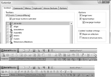
When users see the CommandManager for the first time, they often ask how to hide the text. You can turn off the text in one of two ways. The easiest way is to right-click in the CommandManager and deselect the Use Large Buttons with Text option, as shown in Figure 2.5.
I will use the interface with the hidden text for the rest of the book, primarily to save space on the printed page. You can't be a beginner forever, and so it is time to learn those feature icons. Remember that if you need help with the name of an icon, you can hover the cursor over the icon and a tool tip will tell you what it is.
Another way to remove text from the CommandManager is to remove it only from selected icons. To do this, first enter the customize mode by choosing Tools ![]() Customize or right-click a CommandManager tab and select Customize CommandManager, and then right-click a button in the CommandManager and change the Show Text setting, as shown in Figure 2.6. The Show Text option is only available when Use large buttons with text is enabled.
Customize or right-click a CommandManager tab and select Customize CommandManager, and then right-click a button in the CommandManager and change the Show Text setting, as shown in Figure 2.6. The Show Text option is only available when Use large buttons with text is enabled.
FIGURE 2.5 Adding or removing text from the CommandManager buttons

FIGURE 2.6 Changing the text setting for individual buttons in the CommandManager

Notice also that the text by default goes to the right side of the icon, but using the RMB menu, you can put the text beneath the icon. With these options and some patience to go through the entire interface, you can almost totally customize the appearance and function of your CommandManager.
The most streamlined and space-efficient way to set up the CommandManager is to remove the text. This arrangement is shown in Figure 2.5, in the lower image. Notice that the CommandManager without text takes up the same amount of height as a normal toolbar, with the added room for the tabs at the bottom. The text can be useful for new users or features that you do not commonly use. Also, notice that with the text turned off, you have room for more toolbar space at the right-hand side of the CommandManager.
The final setting for the CommandManager appearance is the size of the icons. You have control over the size of the icon images in the CommandManager. You can find this setting in the Customize dialog box (Tools ![]() Customize), and it is shown in the upper-right side of Figure 2.7. The difference between large and small icons is shown in the lower part of the figure.
Customize), and it is shown in the upper-right side of Figure 2.7. The difference between large and small icons is shown in the lower part of the figure.
This setting applies to all the toolbar icons except the Menu Bar, RMB menu, and Context Bar icons. The setting does apply to the S shortcut toolbar and the Heads-up View toolbar, which I discuss later in this section. Large icons can be useful on displays with very high resolution, in particular on laptops where the screen itself may be small but the resolution is very high. All the screen shots in this book are taken with the Large Icons option turned on for improved visibility. There is often a small difference between the appearance of the large and small icons, aside from size.
Recognizing the limitations of the CommandManager
If you undock the CommandManager, you cannot reorient the tabs horizontally. They remain vertical. In addition, you cannot place multiple rows of toolbars on the same row as a CommandManager using large buttons with text. You cannot dock the CommandManager to the bottom of the SolidWorks window. Another minor limitation is that although SolidWorks enables you to place toolbars at the right end of the CommandManager as well as above it, it does not allow you to place them to the left of the CommandManager or below it.
FIGURE 2.7 Setting large icons
Using toolbars
The point of the CommandManager is to enable you to have many toolbars available to you in a single click, with the main goals being organization and saving space. SolidWorks is a complex program, with a sprawling interface. The CommandManager does a good job of making most of it available to you quickly without taking up a lot of space. Unfortunately, when you save one thing, you usually wind up giving up something else. Interface setup is frequently about compromise or balancing conflicting concerns. In the case of the CommandManager, the compromise is between screen space, mouse travel, and clicks. You may find yourself clicking frequently back and forth between the Sketch and Features tabs. For this reason, in my interface setup, I put the Sketch toolbar vertically on the right side of the graphics window and remove it from the CommandManager. This enables me to see the Sketch and Features toolbars at the same time and greatly reduces the number of times I have to click back and forth between the CommandManager tabs.
The SolidWorks interface performs best with some customization. No two people set it up exactly the same, but everyone needs some adjustment because they might be working on specialized functionality such as molds or surfacing, or they might work with limited functionality, such as predominantly revolved features. Of course, customization can also accommodate personal preferences, for example, if one user prefers to use hotkeys and another uses menus or even the S key.
You can enable and disable toolbars in several ways. To enable a toolbar, right-click in a toolbar area and you will be presented with a list of toolbars in SolidWorks. Another way to do this is to use the Customize dialog box by choosing Tools ![]() Customize, or the Customize option near the bottom of the RMB toolbar list. Yet another way is to choose View
Customize, or the Customize option near the bottom of the RMB toolbar list. Yet another way is to choose View ![]() Toolbars.
Toolbars.
Exploring the Heads-up View toolbar
The Heads-up View toolbar appears along the middle of the top edge of the graphics window. Figure 2.8 shows the default arrangement of the Heads-up View toolbar, and it is shown in relation to the rest of the interface in Figure 2.1.
FIGURE 2.8 The Heads-up View toolbar
![]()
You can customize the Heads-up View toolbar by using the Toolbars dialog box (Tools ![]() Customize
Customize ![]() Toolbars). Customization includes turning the Heads-up View toolbar on or off and adding or removing buttons. These customization options were introduced in SolidWorks 2010. Previously, you could not turn it off, and it had a special way of adding and removing toolbar buttons. If you have multiple document windows or multiple view ports showing, the Heads-up View toolbar only shows in the active window or view port. This toolbar often overlaps with other interface elements when several windows are tiled or if the active window is not maximized, such as the PropertyManager if it is pulled out of the FeatureManager.
Toolbars). Customization includes turning the Heads-up View toolbar on or off and adding or removing buttons. These customization options were introduced in SolidWorks 2010. Previously, you could not turn it off, and it had a special way of adding and removing toolbar buttons. If you have multiple document windows or multiple view ports showing, the Heads-up View toolbar only shows in the active window or view port. This toolbar often overlaps with other interface elements when several windows are tiled or if the active window is not maximized, such as the PropertyManager if it is pulled out of the FeatureManager.
Cross-Reference
Chapter 3 covers the Confirmation Corner in more detail.
Exploring the Menu Bar toolbar and menu
The Menu Bar toolbar is found just to the right of the SolidWorks logo on the title bar in the top-left corner of the SolidWorks window. By default, it contains most of the elements of the Standard toolbar, and it is available even when no documents are open. It uses mostly flyout toolbar icons, so again it follows the trend of saving space at the expense of an extra click. This toolbar can be customized in the same way as normal toolbars in the Customize dialog box in the Commands tab. This toolbar cannot be turned off, but you can remove all the icons from it.
Note
You could run the SolidWorks interface from just the CommandManager without any additional toolbars; you could do the same with just the Menu Bar toolbar, customizing it with all flyout toolbars. The main advantages of the Title Bar toolbar are that it is visible when no documents are open, and that it makes use of otherwise wasted space in the title bar. You might set up the interface for a 12-inch normal aspect display laptop very differently from that of a desktop unit with a 24-inch-wide screen.
There is also a Menu Bar Menu, which is hidden by default. The SolidWorks logo in the upper left of the SolidWorks window or the small triangle next to the logo serve as a flyout to expand the main SolidWorks menus. You can pin the menus in place using the pushpin shown at the right end of the menus in Figure 2.9. When the menu is pinned, the toolbar moves to the right to accommodate it.
Note
The 3Dcontrol menu entry is not part of base SolidWorks; it is part of the 3Dconnexion (spaceball) driver.
Notice that on low resolution or non-maximized SolidWorks windows, you can run into some space problems if the Menu Bar Menu is pinned open. Figure 2.9 shows the SolidWorks 2011 interface with all default settings displayed at 1024 × 768 resolution, which is a common resolution when using digital LCD projectors or small notebook computers. You need to examine the changes in the SolidWorks interface with display size in mind. You might consider having different sets of settings for using a laptop at a docking station with a large monitor, using the laptop with a small monitor, or using the computer with a low-resolution digital projector.
FIGURE 2.9 The Menu Bar toolbar and menu

Looking at the Flyout toolbar buttons
SolidWorks saves space by putting several related icons on the flyout toolbars. For example, the Rectangle tool has several different ways to make a rectangle, with a button for each, and they are all on the rectangle flyout.
You can see all the available flyouts in the Customize menu (Tools ![]() Customize), under the Commands tab, in the first listing in the window, Flyouts.
Customize), under the Commands tab, in the first listing in the window, Flyouts.
The purpose for flyouts is primarily to save toolbar space when several tools are closely related. SolidWorks has set up flyouts in two configurations: flyouts that always maintain the same image for the front button (such as the Smart Dimension flyout) and flyouts that use the last used button (such as the Rectangle flyout).
Toolbar flyouts are listed in Tools ![]() Customize
Customize ![]() Commands and are listed from 2D to 3D through the Weldments toolbar. After Weldments in the list, the flyouts are Similar Function flyouts. You can change the order of the items in the flyouts by changing the order of the items in the toolbars. Just display the original toolbar and choose Tools
Commands and are listed from 2D to 3D through the Weldments toolbar. After Weldments in the list, the flyouts are Similar Function flyouts. You can change the order of the items in the flyouts by changing the order of the items in the toolbars. Just display the original toolbar and choose Tools ![]() Customize to reorder it to your liking. These toolbars will always have the same icon on the top. For example, if you use the Reference Geometry flyout to access the Axis command, the image for the Plane icon will remain on top. The image on top is considered the most commonly used function of that group of tools, and so remains on top.
Customize to reorder it to your liking. These toolbars will always have the same icon on the top. For example, if you use the Reference Geometry flyout to access the Axis command, the image for the Plane icon will remain on top. The image on top is considered the most commonly used function of that group of tools, and so remains on top.
Add-in flyouts, such as the FeatureWorks flyout, are controlled by that specific add-in and again keep the same icon always on top.
The flyouts used for tools of similar function are split between using the most recently used tool icon on top and keeping a consistent icon on top. The only tools that appear to follow the latest icon method are the Sketch Entities tools. Sketch tools and other flyouts use a hard-coded top image.
Exploring the Context toolbars
Context toolbars are toolbars that appear in the graphics window when you right-click or left-click something. When you right-click, a context toolbar appears at the top of the RMB menu and shows the functions that SolidWorks deems the most commonly used functions. This is a static list and does not change as you use the buttons. These functions are removed from the RMB menu and replaced with the Toolbar icon in a toolbar above the abbreviated RMB menu, as Figure 2.10 shows.
FIGURE 2.10 The right-click menu and context toolbar
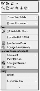
An identical toolbar appears when you click (left-click) an item on screen. When this toolbar appears with a left-click, the rest of the RMB menu does not appear. Tool tips are available if you do not recognize the icons on the toolbar. For reference, the icons in the context toolbar atop the RMB menu (the icons without text) shown in Figure 2.10 are in order from the upper-left: Edit Feature, Edit Sketch, Suppress, Rollback, Select Other, Sketch, Hide Body, Zoom To Selection, Normal To, and Appearance Callout. Notice that these selections do not reappear in the main RMB menu.
These context toolbars are not editable, but you can turn them off and put the RMB menu back to its complete configuration. To turn off the context toolbars, click the context toolbar and choose Tools ![]() Customize. Use the options on the right side of the main Toolbars tab, as shown in Figure 2.11.
Customize. Use the options on the right side of the main Toolbars tab, as shown in Figure 2.11.
FIGURE 2.11 Context toolbar settings

I find that the RMB context toolbars are distracting because they force you to read a two-dimensional list of icons and a one-dimensional list of text. To me, this is just too confusing. I turn these off so that the RMB menus look like they always did. However, I do find left-click context toolbars useful for things like Hide Sketch, Edit Feature, Edit Sketch, Appearance Callout, sketch relations, and so on. When I use the RMB menus, I'm looking for a more general function. When using the left-click context bars, I'm looking for something specific that I know is there. In Figure 2.11, the Show on selection check box option simply refers to the left-click toolbar, and Show in shortcut menu check box option refers to the RMB menu.
The purpose of the context toolbars is to save space by condensing some commands into a toolbar without text instead of a menu with icons and text. The left- and right-click toolbars are the same, but they work differently. The left-click context toolbar fades as you move the cursor away from it and becomes darker as you move the cursor toward it. Once it fades past a certain point, you cannot get it back, except if you have Ctrl+selected multiple entities. The context toolbar does not appear until you release the Ctrl key. To get a context menu to show up again after it has faded, you can just move the cursor back to approximately where the toolbar would have been and press Ctrl again. This works only for multiple selection menus where Ctrl was used to multi-select. The functionality is probably a bug, or unintentional in any case, or else it would also work somehow for single selections.
Exploring the Shortcut “S” toolbar
The Shortcut toolbar is also known as the “S” toolbar because by default you access it by pressing the S key. You can customize this toolbar for each document type and another for sketches, so it can have different content for sketches, parts, assemblies, and drawings. To customize the “S” toolbar, right-click it when it is active and click Customize from the RMB menu, as shown in Figure 2.12.
Many people claim to have customized the “S” toolbar to such an extent that they have been able to remove the CommandManager and all other toolbars from their interface. This is possibly true if you use a limited number of sketch entities, sketch relations, and feature types, or make extensive use of flyouts on the “S” toolbar. However, if you work with a wide range of tools (say, surfacing, sheet metal, and plastic parts), you may need some additional toolbar space. It is completely believable to have access to most of the software's function with the “S” toolbar and either the Menu Bar toolbar or the CommandManager. CommandManager by far gives you the most flexibility, but it also requires the most space.
FIGURE 2.12 Right-click on the Shortcut “S” toolbar to customize it.

The “S” key shortcut may conflict with another keyboard customization you have done, depending on how your software was installed. To change the “S” toolbar key to another character or to reassign it, follow the directions for creating and maintaining hotkeys later in this chapter in the section on customization. It is referenced as the Shortcut Bar in the Keyboard list (Tools ![]() Customize
Customize ![]() Keyboard).
Keyboard).
Using Tool tips
Tool tips come in two varieties: large and small. Large tool tips show the name of the tool and available shortcut keys, along with a brief description of what it does. Small tool tips show only the tool's name and shortcut keys. To change the tool tip display from large to small, or to deselect the tool tip display altogether, choose Tools ![]() Customize. The options for using large tool tips and showing tool tips appear in the upper-right corner, as shown in Figure 2.11. In addition to the tool tip balloons, tips also appear in the status bar at the bottom of the screen when the cursor is over an icon. Figure 2.13 shows a comparison between large and small tool tips.
Customize. The options for using large tool tips and showing tool tips appear in the upper-right corner, as shown in Figure 2.11. In addition to the tool tip balloons, tips also appear in the status bar at the bottom of the screen when the cursor is over an icon. Figure 2.13 shows a comparison between large and small tool tips.
FIGURE 2.13 SolidWorks uses large tool tips by default.

Note
The Customize option (Tools ![]() Customize) is inactive unless a SolidWorks document is open. To access the Customize dialog box, first open a SolidWorks part, assembly, or drawing and then choose Tools
Customize) is inactive unless a SolidWorks document is open. To access the Customize dialog box, first open a SolidWorks part, assembly, or drawing and then choose Tools ![]() Customize from the menu. Customize is different from the Customize Menu option found in all SolidWorks menus. The Customize Menu option is discussed later in this chapter.
Customize from the menu. Customize is different from the Customize Menu option found in all SolidWorks menus. The Customize Menu option is discussed later in this chapter.
Managing toolbars
After all that, if you still feel you need to work with standard toolbars, it is easy to move, select and deselect, and add icons to toolbars. It is important to remember that different document types retain different toolbar settings; for example, the toolbars that you see with a part open are different from the toolbars that you see for drawings.
When you are working on parts, it is important to have both the Sketch and the Features toolbars active. When you are working on a drawing, you will never use the Features toolbar, but you will frequently use the Sketch toolbar. Likewise, for assemblies, you may want to display some additional toolbars and eliminate others. For this reason, when you change from a part document to a drawing document, you may see your display adjust because the changing toolbars increase or decrease the amount of space that is required.
Best Practice
It is best practice to set up the toolbars for each document type so that they take up similar amounts of space — for example, two rows on top and one column to the right. This way, changing between document types is not so jarring, and the graphics area does not need to resize for each change.
Moving toolbars
To move a toolbar, you can click with the cursor at the dotted bar on the left end of the toolbar, as shown in Figure 2.14. The cursor changes to a four-way arrow and you can then drag the toolbar where you want it. Toolbars dock either vertically or horizontally. You can resize undocked toolbars so that they have rows and columns. This arrangement is typically used with the Selection Filter toolbar, which is often left undocked and compressed into a block that is three or four columns wide.
If the SolidWorks window is not wide enough for the toolbar to fit entirely in the screen, double arrows like those shown in Figure 2.15 appear at the end of the truncated toolbar. When you click the double arrows, a flyout toolbar appears with the missing icons, as shown in Figure 2.16.
FIGURE 2.14 Dotted bars enable you to move toolbars.
![]()
FIGURE 2.15 A truncated toolbar showing double arrows
![]()
FIGURE 2.16 You can display all of a truncated toolbar by clicking the double arrows.
Using flyout toolbars
You can use any toolbar as a flyout toolbar. Figure 2.17 shows the list of all flyout toolbars, which is the same as the list of all toolbars. Flyout toolbars are a nice space-saving feature for tools that you use infrequently, but frequently enough to want to avoid going through the menus. To use a toolbar as a flyout, select it from the Flyout toolbars list and drag it onto an existing toolbar. It displays with an arrow to the right. Clicking the arrow causes all the tools to scroll out temporarily until you click a toolbar icon or anything else.
To add icons to a flyout toolbar, temporarily show the regular toolbar that corresponds to the flyout toolbar and add icons to the regular toolbar. When you are done adding or removing icons, turn off the regular toolbar; the changes are applied to the flyout.
FIGURE 2.17 The Flyout toolbars are on the Commands tab in the Customize dialog box.

Tip
If you want to create a separate toolbar, you can commandeer an existing one for your own purposes. For example, because I do not use the Tools toolbar, I have removed all the regular icons from it and replaced them with relevant flyout toolbars, which I do use extensively. This enables me to consolidate space and not have unused icons on my toolbars. Alternatively, creating a custom CommandManager tab and putting on it what you like is much easier.
Working in Full Screen mode
Full Screen mode enables you to toggle quickly to the display so that only the graphics window and the Task pane appear; the FeatureManager, menus, toolbars, and status bar are all hidden. Alternatively, you can hide just the FeatureManager or the toolbars.
In Full Screen mode, you can still access the menus by clicking the cursor along the top border of the window, as shown in Figure 2.18.
- To toggle to Full Screen mode, press the F11 key.
- To toggle the toolbar display, press the F10 key (see Figure 2.18).
- To toggle the FeatureManager display, press the F9 key.
Customizing your workflow
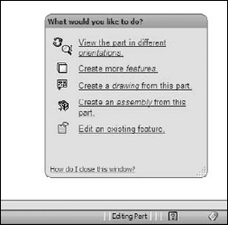
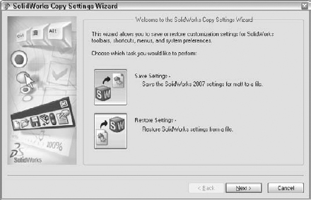
When you first install and run the SolidWorks software, the SolidWorks Welcome screen shown in Figure 2.19 offers you the option to customize the interface using one of three preset option packages. Special menu and toolbar settings are made for Consumer product design, Machine design, or Mold design. After the software is initially installed, you only see this screen once, but you can change all the options in other places, including the Options tab in the Customize dialog box.
FIGURE 2.18 The SolidWorks window with all toolbars hidden using the F10 key

FIGURE 2.19 The Welcome to SolidWorks screen

The three-workflow customizations affect the interface as follows:
- Consumer product design adds the Surfaces toolbar to the CommandManager.
- Machine design adds Sheet Metal and Weldments toolbars to the CommandManager.
- Mold design adds Surfaces and Mold Tools toolbars to the CommandManager.
Similar changes are made to the menus to hide or show menu selections as appropriate. You can find more information about hiding and showing menu items later in this chapter.
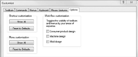
If you want to select a different option after the initial setup, choose Tools ![]() Customize and click the Options tab, where you can specify a different choice. Figure 2.20 shows the Options tab of the Customize dialog box.
Customize and click the Options tab, where you can specify a different choice. Figure 2.20 shows the Options tab of the Customize dialog box.
FIGURE 2.20 The Options tab of the Customize dialog box, where you can select a different workflow customization
Controlling menus
Everyone has his own style of working. For example, some people like to use menus and others do not. Some like to use hotkeys and others like the mouse. Modify Section View is an example of a tool that you cannot access via toolbars. It can only be accessed via the menus.
The most frequently used menu items are in the View, Insert, and Tools menus. All the menus shown in this section have all the possible options selected. As a result, the View menu in Figure 2.21 may contain options that are not available on your computer. Customizing menus is covered later in this chapter. Figure 2.21 also shows the Insert and Tools menus, along with an image of a menu with the Customize Menu mode activated.
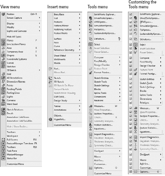
You use the View menu primarily for turning on or off the visibility of entity types such as planes, sketches, or temporary axes. You can also do this by using hotkeys or by putting extra items on the View toolbar.
The Insert menu is used mostly for creating feature types for which you do not have a toolbar icon on the screen. For example, although the Move Face tool is on the Mold Tools toolbar, it has many uses aside from mold design. You can find the Move Face tool by choosing Insert ![]() Face.
Face.
The Tools menu is used primarily for sketch entities or tools for which you have no icon on the screen. Several other commonly used tools, such as Measure, Equations, Customize, and Options, are also available in this menu.
You can customize menus by adding or omitting items. By using the Customize Menu option at the bottom of any menu — including shortcut (RMB) menus — you can remove items from any menu by clearing the check boxes next to tools that you do not use. To bring back the removed items, you can either go back to the Customize Menu or choose Tools ![]() Customize
Customize ![]() Options and click the Reset to Defaults buttons for menu and shortcut customization.
Options and click the Reset to Defaults buttons for menu and shortcut customization.
Note
Be careful not to confuse this Customize Menu selection with the Customize menu selection on the Tools menu. Figure 2.21 shows the Tools menu being customized. In addition, I do not recommend removing items from the menus. It doesn't take much for someone to need one of those items and no one remembers that it was supposed to be there or how to get it back.
Interpreting SolidWorks Use of the Word “Shortcut”
Between the SolidWorks and Microsoft interfaces, the word shortcut is used in several overlapping and confusing ways. Users replace most of the SolidWorks occurrences with words they use every day. The following list describes where SolidWorks and Microsoft users might encounter the word shortcut as a formal name for interface functionality, and how they might understand it.
 The Windows Shortcut link to another file or folder. Most users still refer to this link as a shortcut or desktop shortcut.
- Shortcuts (as identified in the SolidWorks Help under Shortcut
 Keys) are either accelerator keys or keyboard shortcuts. Users refer to accelerator keys as Alt-keys, and to keyboard shortcuts as hotkeys.
 - SolidWorks shortcut menus are commonly called the right mouse button (RMB) menus, and have detached toolbars called context bars for both right- and left-click options. These are commonly known as the RMB bar and the LMB bar.
- Shortcut tabs (found as the “shortcut” entry in the SolidWorks Help) presumably refer to DriveWorksXpress functionality, although there is no direct mention of that in the Help entry. DriveWorksXpress is described in more detail in the SolidWorks 2011 Assemblies Bible (Wiley, 2011).
- Shortcut bars are commonly known as the S key toolbar.
If you use the alternate terminology offered here, it will be clear to all users what you are talking about.
The Options dialog box (Tools ![]() Customize
Customize ![]() Options), shown in Figure 2.20, contains the Shortcut (RMB) menu and Menu customization options. These options enable you to show all the menu items for both types of menus in a single stroke. By default, some items are hidden in various menus. Keyboard customization is discussed later in this chapter. Keyboard shortcuts are generally referred to as hotkeys.
Options), shown in Figure 2.20, contains the Shortcut (RMB) menu and Menu customization options. These options enable you to show all the menu items for both types of menus in a single stroke. By default, some items are hidden in various menus. Keyboard customization is discussed later in this chapter. Keyboard shortcuts are generally referred to as hotkeys.
Changing cursors
SolidWorks cursors are context sensitive and change their appearance and function depending on the situation. Sketching cursors display a pencil and the type of sketch entity that you are presently sketching. Sketch cursors also display some dimensional information about the entity that you are sketching, such as its length or radius. Sketch cursor feedback is necessary for fast and accurate sketching.
Cross-Reference
To learn more about sketch cursor feedback, see Chapter 3.
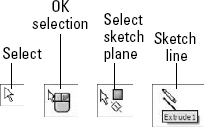
The Select cursor changes depending on the item over which you have positioned it. Cursor symbols also help remind you when selection filters are active. The cursor is frequently available as an OK button. For example, after selecting edges for a Fillet feature, the RMB functions as an OK button. Figure 2.22 shows various cursors and their significance.
FIGURE 2.22 Various SolidWorks cursors
Working with models in the FeatureManager and PropertyManager windows
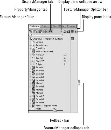
The FeatureManager window is the panel to the left of the screen, which shows an ordered list of features describing how the part was built. SolidWorks users spend a fair amount of time using the FeatureManager to edit or inspect models. Figure 2.23 shows the FeatureManager for a simple model.
Using the FeatureManager
![]() There is a splitter bar at the top of the FeatureManager that enables you to split the FeatureManager window into two windows, enabling you to display the FeatureManager and another window, such as the PropertyManager (see Figure 2.24). Small arrows in the middle of the right separator can collapse the FeatureManager to increase screen space. The F9 key also collapses or opens the FeatureManager (refer to Figure 2.23).
There is a splitter bar at the top of the FeatureManager that enables you to split the FeatureManager window into two windows, enabling you to display the FeatureManager and another window, such as the PropertyManager (see Figure 2.24). Small arrows in the middle of the right separator can collapse the FeatureManager to increase screen space. The F9 key also collapses or opens the FeatureManager (refer to Figure 2.23).
FIGURE 2.23 The FeatureManager for a simple model
Looking at the Display pane
![]() You can open the Display pane flyout from the FeatureManager by using the double arrows at the top-right corner of the FeatureManager. The Display pane helps you to visualize where appearances, display styles, or hidden bodies have been applied in a part document and additional functions in an assembly document. The display pane is helpful when you're looking for colors that are applied to the model at some level other than the part level.
You can open the Display pane flyout from the FeatureManager by using the double arrows at the top-right corner of the FeatureManager. The Display pane helps you to visualize where appearances, display styles, or hidden bodies have been applied in a part document and additional functions in an assembly document. The display pane is helpful when you're looking for colors that are applied to the model at some level other than the part level.
Cross-Reference
Appearances are covered in more detail in Chapter 5.
Looking at the Rollback bar
![]() The Rollback bar at the bottom of the FeatureManager enables you to see the part in various states of history. Features can be added while the rollback bar is at any location. The model can also be saved while rolled back.
The Rollback bar at the bottom of the FeatureManager enables you to see the part in various states of history. Features can be added while the rollback bar is at any location. The model can also be saved while rolled back.
Looking at the FeatureManager filter
![]() One of the most useful elements of the FeatureManager is the FeatureManager filter. The filter resides at the top of the FeatureManager. If you type text in the filter, SolidWorks searches feature names, descriptions, comments, tags, and dimension names for text matching the string, and only shows matching features in the window. This also works in assemblies, where you can filter for part names or document properties. The filter is very useful for quickly finding parts, features, mates, or anything else that shows up in the part or assembly FeatureManager.
One of the most useful elements of the FeatureManager is the FeatureManager filter. The filter resides at the top of the FeatureManager. If you type text in the filter, SolidWorks searches feature names, descriptions, comments, tags, and dimension names for text matching the string, and only shows matching features in the window. This also works in assemblies, where you can filter for part names or document properties. The filter is very useful for quickly finding parts, features, mates, or anything else that shows up in the part or assembly FeatureManager.
Using the PropertyManager
![]() The PropertyManager is where you go to set most of the feature parameters and where you edit the properties of selected items such as sketch elements. You can manually switch to the PropertyManager using the tabs on the top of the Display panel or allow it to pop up automatically when your input is needed. The leftmost tab in the row of icons is the FeatureManager tab, the second from the left is the PropertyManager tab, the second from the right is the ConfigurationManager tab, and the rightmost tab is the DimXpertManager. Other icons may also appear in this area for drawings or if you have add-ins such as PhotoWorks or SolidWorks Simulation (formerly COSMOS) turned on. The ConfigurationManager tab appears with more detail in Chapter 11
The PropertyManager is where you go to set most of the feature parameters and where you edit the properties of selected items such as sketch elements. You can manually switch to the PropertyManager using the tabs on the top of the Display panel or allow it to pop up automatically when your input is needed. The leftmost tab in the row of icons is the FeatureManager tab, the second from the left is the PropertyManager tab, the second from the right is the ConfigurationManager tab, and the rightmost tab is the DimXpertManager. Other icons may also appear in this area for drawings or if you have add-ins such as PhotoWorks or SolidWorks Simulation (formerly COSMOS) turned on. The ConfigurationManager tab appears with more detail in Chapter 11
One of the benefits of putting all of the data entry into the PropertyManager is that it saves a lot of space on the screen. On the other hand, you will often need to make a selection from the FeatureManager at the same time that the PropertyManager pops up and takes its place. You can disable this automatic popup behavior by choosing Tools ![]() Options
Options ![]() System Options
System Options ![]() General and selecting the Auto-show PropertyManager setting.
General and selecting the Auto-show PropertyManager setting.
My favorite option for dealing with the PropertyManager is to detach it from the FeatureManager so that you can see the two side by side instead of one or the other. To detach the PropertyManager, drag its icon from the tabs out into the graphics area and release. Once the PropertyManager is detached, you can move it to a second monitor, float it within the SolidWorks window, or dock or reattach it. To put it back in its place under the FeatureManager, just drag it back on top of the FeatureManager using one of the docking station symbols on the screen, allow it to snap into place, and release it.
Caution
The detached PropertyManager does not automatically expand to match the size of the data included in it. You will often have to widen or lengthen the size of the detached PropertyManager window to see everything in it. This is a bug that has been around since this functionality was introduced.
If you do not like the detachable PropertyManager, you can use the splitter bars either to put the FeatureManager on top and the PropertyManager beneath or use the flyout FeatureManager. When creating or editing a feature, you can access the flyout FeatureManager by double-clicking the name of the feature at the top of the PropertyManager. The flyout FeatureManager is displayed just to the right of the regular FeatureManager, in the main graphics window, and is transparent to enable you to see the model through it. The various ways of combining the FeatureManager and PropertyManager are shown in Figure 2.24.
FIGURE 2.24 The detached PropertyManager, the split FeatureManager, and the flyout FeatureManager

Introducing the DisplayManager
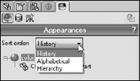
The terminology around the various interface devices that are used to show, edit, and place colors (appearances) on part and assembly models becomes more complex with every release. SolidWorks 2011 introduces the DisplayManager. This interface element is separate from the Display pane and the Appearances panel of the Task pane. The DisplayManager helps you understand the various display-related items that might be applied to your model. Figure 2.25 shows the DisplayManager with the Appearances active. Chapter 5 discusses the DisplayManager in more depth.
FIGURE 2.25 The DisplayManager helps you sort through everything that affects how the model looks.
Getting around the Task pane
By default, the Task pane sits to the right of the SolidWorks screen, although you can undock it entirely. If you want to keep it open, click the pushpin in the upper-right corner of the pane. The Task pane is shown in Figure 2.26.

The Task pane is the home for several panels:
- SolidWorks Resources. These are useful links for templates, tutorials, tech support, news, GlobalSpec search, Tip-of-the-Day, and other resources.
- Design Library. This includes locally stored libraries, Toolbox, and 3D Content Central. This tab also contains “SolidWorks Content,” which consists of additional library resources that can be downloaded directly from the Task Pane.
- File Explorer. This is a Windows Explorer interface that you can use to browse for files.
- SolidWorks Search. This panel allows you to perform searches that include the SolidWorks Knowledge Base and the SolidWorks Community Forum, as well as filename and custom properties for SolidWorks files on your computer or network.
- View Palette. This palette enables you to visually select views and drag them onto a drawing sheet.
- Appearances, Scenes, and Decals. This panel enables you to select appearances and scenes for your SolidWorks documents. SolidWorks has also moved decals into the SolidWorks Standard level of the software instead of being part of the rendering software.
- Custom Properties. The custom property tab in Task pane enables you to create a custom interface that goes inside this Task Pane tab that will help you enter custom property data quickly, easily, and accurately.
- Recovered Documents. After a crash, auto-recovered documents are listed in this special purpose Task Pane tab.
Getting familiar with the Status bar
The status bar is a nonintrusive way in which SolidWorks communicates information back to the user. It is located at the bottom of the screen, and you can enable it from the View menu. Figure 2.27 shows the status bar in action.
FIGURE 2.27 The status bar showing a tool tip for the Sketch Circle tool
![]()
The status bar can display the following information, indicators, and icons:
- Progress as parts, assemblies, or drawings load
- Tool tips for commands
- Measurements
- The sketch status for an active sketch
- In-context editing
- Suspend automatic rebuilds
- Icons that enable you to turn Quick Tips off or on
- The sheet scale for drawings
- The cursor position for drawings and sketches
- Whether you are editing the sheet, sheet format, or view of a drawing
Assigning tags
Tags work like document properties, except that they do not need a property name; they just use a value. A tag could be considered simply a keyword that you can associate with a part in an assembly or even a feature in a part. Tags can be searched by SolidWorks Explorer or by the FeatureManager Filter. You can assign tags by clicking the yellow tag icon on the status bar in the lower-right corner of the SolidWorks window. Figure 2.28 shows a tag being added to a feature.
Making use of Quick Tips
Quick Tips appear in the popup window in the lower-right corner of the graphics window. They can change as you work so that they are sensitive to the context in which you are working. They are a great way for new users or infrequent users to learn or be reminded of the next steps available to them. You can activate and deactivate Quick Tips by clicking the question mark icon in the lower-right corner of the SolidWorks window on the status bar. Figure 2.29 shows the Quick Tips window in action.
FIGURE 2.28 Adding a tag to a feature

FIGURE 2.29 Quick Tips in action
Using SolidWorks Search
You can find SolidWorks Search in the upper-right corner of the SolidWorks application window, on the title bar, as shown in Figure 2.30.
FIGURE 2.30 Accessing SolidWorks Search

SolidWorks Search enables you to search the SolidWorks Help, Knowledge Base, or community forums for information (some of these require an Internet connection and login), as well as look for SolidWorks models on your local or network drives.
Searching for files
The file searches include 3D ContentCentral, SolidWorks Explorer, and SolidWorks Workgroup PDM if it is installed. Figure 2.31 shows the interface for searching for files.
FIGURE 2.31 Using SolidWorks Search to search for files

To configure where SolidWorks is going to search for files, you can use the options at Tools ![]() Options
Options ![]() File Locations
File Locations ![]() Search Paths. Remember that SolidWorks follows search rules that force it to look in directories that may not be obvious to you, including recent folders where you have saved documents and other directories. You can also select custom properties to search from the drop-down list.
Search Paths. Remember that SolidWorks follows search rules that force it to look in directories that may not be obvious to you, including recent folders where you have saved documents and other directories. You can also select custom properties to search from the drop-down list.
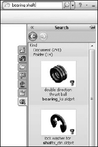
Figure 2.32 shows the result list displayed in the Search tab of the Task pane. This allows you to quickly view the search results along with the filenames to pick out the files you are looking for.
FIGURE 2.32 Browsing search results
Searching for help
SolidWorks Search appears to only work with the Web Help feature. As a result, if you do not have an Internet connection, you cannot access the Help feature through Search, and the KB and forums are also Web based. If you have no Internet connection, just look through the local Help feature manually.
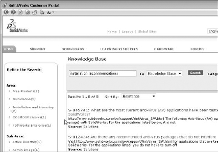
Figure 2.33 shows the results of searching the Knowledge Base for the phrase “installation recommendations.” There are plenty of relevant entries to browse. A similar results window appears if you choose to search the forums.
FIGURE 2.33 Searching the Knowledge Base for installation tips
There is not a way to search all three sources of technical information at the same time. Thus, to search all three locations, you have to search each one individually.
Using the 2D Command Line Emulator
This is a tool specifically for people who are coming to SolidWorks from AutoCAD. As the name suggests, it adds a command line to the bottom of the SolidWorks window that works like the AutoCAD command line in most respects. The available commands are somewhat limited compared to those that are available in AutoCAD. This tool only functions in the 2D sketch mode, on a drawing sheet, or in a drawing view; it does not work in a 3D sketch. The 2D Command Line Emulator is shown in Figure 2.34.
Available sketch tools in the 2D Command Line Emulator include Align, Arc, Array, 'Cal, Chamfer, Chprop, Circle, 'Color, Copy, DDcolor, Dim, Dist, Ellipse, Erase, Exit, Extrude, Fillet, 'Grid, Line, List, Massprop, Mirror, Move, Offset, 'Ortho, 'Osnap, 'Pan, Plot, Point, Polygon, Qsave, Rectangle, 'Redraw, 'Redrawall, Revolve, Rotate, Save, Saveas, 'Snap, Spline, Trim, U (undo), 'Units, 'View, and 'Zoom. You can use commands preceded by an apostrophe (') as transparent commands without exiting an active command. Notice that even the cursor changes to crosshairs.
FIGURE 2.34 The 2D Command Line Emulator in action

Best Practice
The best way to learn a new software package is to embrace the new way, not to cling to the old way. Although AutoCAD users may find the 2D Command Line Emulator more comfortable to work with, you will not achieve the same results as you will with the SolidWorks default-sketching mode. For example, the resulting sketch entities created using the 2D Command Line Emulator are not constrained in any way, and the endpoints do not even merge. You can deselect the 2D Command Line Emulator by going to Tools ![]() Add-ins.
Add-ins.
Note
The 2D Command Line Emulator is not available on 64-bit versions of SolidWorks.
Making the Interface Work for You
As engineers and designers, we all like to tinker with things to optimize efficiency and to apply our personal stamp. When the SolidWorks software is installed, the interface is functional, but not optimal. Earlier in this chapter, I discussed managing and customizing toolbars and menus. In the remainder of this chapter, I will focus more on customizing the interface and suggest some strategies that you might use to help customize your work environment.
Customizing colors
You need to be aware of a few things before you change the standard colors in the SolidWorks interface. The first is that SolidWorks does not automatically alter text color to contrast with your background. As a result, if you set the background to black, and the text is black, you won't be able to see the text. This may seem obvious to some people, but AutoCAD automatically changes text color to contrast with the viewport background, and so AutoCAD users may take this functionality for granted.
Exploring default selection colors
All the interface colors are controlled in the Systems Options Colors dialog box. You can access the dialog box by choosing Tools ![]() Options
Options ![]() Colors. The selection color in particular is set at Selected Item 1, as shown in Figure 2.35.
Colors. The selection color in particular is set at Selected Item 1, as shown in Figure 2.35.
FIGURE 2.35 Changing interface colors

Notice that you can set a color scheme. I recommend that if you want to change the colors used in the interface, you save the settings as a color scheme so that the scheme can be re-created easily later or copied to another computer. Color schemes are stored in the Windows registry, not as separate files. To transfer color settings to another computer, you will need to either use the Copy Settings Wizard or manually copy data from the Windows registry.
Before making changes, you might consider saving your initial settings as a separate scheme so you can get back to them if you need to.
Caution
Making changes to the Windows registry can adversely affect software installation and hardware performance. You should not attempt changes to the registry unless you know exactly what you are doing.
Selecting background options wisely
You should avoid some colors for the background, or you should make some changes if you choose these colors. Black is used with fully defined sketches, dimensions, FeatureManager text, and annotations. Blue can mask the underdefined sketch color. Bright green (or blue, depending on the version you are using) can cause problems with seeing selected items. Bright red, aside from being a terrible color to stare at all day, also does not contrast well with some of the red highlights and error colors.
You might think that no matter which color background you select, aside from the default, the items or features are difficult to see. For this reason, many users choose a gradient background, which enables them to pick colors where items are always visible on one-half of the screen or the other. Staring at a white screen all day can be uncomfortable for your eyes, so pick colors that enable you to see everything with “reasonable” contrast, yet are not glaringly bright. Very high contrast is hard on the eyes, and low contrast may make it difficult to distinguish items on the screen.
You have to consider what the purpose of the background is. Some people doing presentations may want the background to be attractive while otherwise staying out of the way. Others may only need the background to contrast with whatever is in front of it in a way that does not strain anyone's eyes. For writing a book, the background generally needs to be white to match the page. No one scheme will suit all needs.
In addition to colors and gradients, you can use an image as the graphics window background. This gives you a wider range of customization capabilities, and several sample images are already available in the default settings. Also, be aware that document scene backgrounds are document specific and override system options.
RealView also adds some capabilities with scenes. Scenes can be applied from the Appearances, Scenes, and Decals tab on the Task pane. Most of the display settings work in conjunction with RealView, which is an advanced display mode. Depending on your graphics card, your computer may or may not be capable of using RealView. SolidWorks offers three different types of scenes: Basic, Studio, and Presentation. Of these, I find the Studio scenes to be the best when I need a reflective floor with shadows; otherwise, I stick with the Basic scenes. I find it distracting to use either reflections or shadows in models while working. However, a nice, shiny RealView appearance to the part is often useful, especially for visualizing curvature on curvy parts. I describe RealView, along with scenes, in more detail in Chapter 5.
Customizing strategies
You can easily customize many aspects of the SolidWorks interface, including:
- Toolbars
- Menus
- Background colors or images
- PropertyManager skins
- Task pane location
- Hotkeys
- Macros
- Custom application programming
Whether or not you should customize each of the previous items depends partially on how much time and energy you have to spend, how much you work with others, whether you share your workstation with other users, and how much money you are ready to dedicate in the case of custom programming.
Considering hotkey approaches
Some of us old-timers prefer to use the keyboard instead of the mouse. If your hand-eye coordination is as bad as mine is, you may also choose this approach. I can type without looking at the keyboard, but when I use the mouse, it takes me a few seconds to aim at an icon and hit it accurately. This means that I customize SolidWorks to use as many hotkeys as possible, and remove icons from the interface if I have them on hotkeys. Unfortunately, my memory is as bad as my eyesight, and so remembering 75 hotkey commands is a bit of a problem. I admit to having a printed list of hotkeys taped to the side of my monitor. While I know that needing to read the list to find a particular hotkey defeats most of the purpose of using them in the first place, I just accept it as a learning aid. This is a self-solving problem, because the hotkeys that I use the most are the ones that I learn most quickly.
I generally do not advocate trying to standardize a hotkey scheme across multiple users, unless the users all agree to it. The underlying reason for writing this section is that everyone remembers things differently in the first place.
Any command that I use more than a few times an hour is worth assigning to a hotkey. I like to use alliteration when assigning keys to help with my faulty memory. The most frequently used commands are assigned single-letter hotkeys, and the less frequently used commands are assigned combinations. Thus, Tools Options is linked to O, Measure to M, Select Vertex to Shift+V, and Curve Projected to Ctrl+J (Ctrl+P is the Windows standard for the Print command). Other people like to group keys into easy-to-reach combinations; this is why the Q, W, A, S, Z, and X keys are often assigned first for right-handed mouse users.
Organizing hotkeys
Hotkeys are assigned and organized in the Keyboard dialog box (Tools ![]() Customize
Customize ![]() Keyboard), as shown in Figure 2.36. This interface enables you to see all the hotkeys (called shortcuts in the list) easily. If you try to enter an existing hotkey, SolidWorks issues a prompt, telling you that the key is assigned to another command and its name. The prompt asks you whether you want to clear the other instance of the hotkey and make the new one active. You can also print out or copy to the Clipboard a list of only commands that use hotkeys.
Keyboard), as shown in Figure 2.36. This interface enables you to see all the hotkeys (called shortcuts in the list) easily. If you try to enter an existing hotkey, SolidWorks issues a prompt, telling you that the key is assigned to another command and its name. The prompt asks you whether you want to clear the other instance of the hotkey and make the new one active. You can also print out or copy to the Clipboard a list of only commands that use hotkeys.
Because the list of commands is so long, a Search function is available, and a drop-down arrow makes only the commands from a selected menu visible. The list of commands is organized by menu name, and the menus are listed as they occur in the interface. Fortunately, on the Keyboard tab, SolidWorks enables you to sort, using the column headers to list the menus, commands, or hotkeys in alphabetical order, simply by clicking the column header. This is a highly usable interface, one of my favorite interface changes in the last several releases.
Hotkeys for menu items are listed on the right side of the regular drop-down menus. These serve more as a learning aid than interface elements. Figure 2.37 shows a drop-down menu with hotkey combinations on it.
FIGURE 2.36 The Keyboard dialog box (Tools ![]() Customize
Customize ![]() Keyboard) and the mouse gesture donut
Keyboard) and the mouse gesture donut
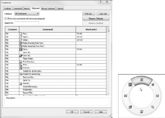
FIGURE 2.37 Drop-down menus contain reminders of the hotkey combinations.
Using mouse gestures
You can customize and use a mouse gesture interface, shown in the second image of Figure 2.37. To make the interface appear, just drag the RMB slightly, about 14 inch. Once you get used to the interface, a drag of about 34 inch in a single motion will activate the commands.
I have found that this interface works best when you have memorized the commands available at various positions around the donut. You can set it to use four or eight divisions. Accuracy is more difficult with the larger number of divisions.
You can establish the donut in four or eight segments; it comes set to four by default. You can also do the customization in the Customize dialog box (Tools ![]() Customize) using the Mouse Gestures tab. The advantage of this interface is that it is very easy to invoke. I like the way you can use the default setup to control views. The mouse moving in a particular direction is easily associated with a view direction, so it should be easy to remember.
Customize) using the Mouse Gestures tab. The advantage of this interface is that it is very easy to invoke. I like the way you can use the default setup to control views. The mouse moving in a particular direction is easily associated with a view direction, so it should be easy to remember.
Mouse gestures will probably not replace hotkeys or the “S” toolbar, but they do add effective quick access for a few functions.
Using the keyboard
Moving between the mouse and the keyboard can be bothersome and time-consuming. In addition to the hotkey approach, you can use another keyboard method to save time. Many users become adept at using the Alt-key combinations to invoke menu items. Most menu items in Windows applications contain a single underlined letter.
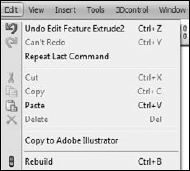
To access a top-level menu, you can hold down the Alt key and press the underlined letter for that menu, and then just press an underlined letter in the menu to access specific commands. This technique enables you to navigate most of the interface without using the mouse. For example, to exit SolidWorks, instead of using the mouse to click the red X in the upper-right corner, you could press Alt+F, X. In Figure 2.38, you can see that the F in File is underlined, as is the X in Exit.
FIGURE 2.38 Alt-Keys in the File menu

You may potentially run into conflicts when using Alt-keys. A combination of Alt + another keyboard key is a valid use of a hotkey combination. If you use any Alt hotkey combinations, it is likely that you have seen a conflict like this. In cases of conflict, the hotkey combination seems to gain priority over the Alt-key accelerator.
Minimizing icons
In order to maximize valuable space on the monitor, many SolidWorks users strive to minimize the number of toolbar icons on the screen, or confine them to two rows of toolbars. You can do this by using the CommandManager, flyout toolbars, the “S” toolbar, right-click toolbars, and hotkeys, and removing unused icons, as well as the other techniques discussed here.
Having an uncluttered workspace is definitely a plus, but having easy access to commands is the real purpose of an interface in the first place. You need to strike a balance between too much and not enough. The more kinds of work you do in SolidWorks, the more tools you will need to have available. If you only create relatively simple machined parts and drawings, you will need fewer tools available than someone who creates complex plastic part assemblies with rendering and animation.
Contemplating device approaches
If you have never used a Spaceball or equivalent view-manipulation device, you should consider it. They are wonderful devices and do far more than just spin the view. Most of the devices also have several programmable buttons that you can link to menu items. They can move drawing views, parts within assemblies, and even manipulate selected objects in other Office applications and Web browsers.
Using touch and multi-touch support
I have written portions of this book on a tablet PC. A tablet might not be ideal for long periods of SolidWorks usage. However, I use it regularly for presentations and even modeling when I really want to get the feel of drawing a line by hand. The stylus is not quite as intuitive as a pencil, but it is less of an impediment to the tactile feel of actual drawings than a clunky mouse. Tablets are a great option when used in combination with the new touch functions in SolidWorks, such as mouse gestures.
The mouse gestures functionality is considered a tool well suited to a tablet interface, where flicking the stylus is easier than mouse clicking. This is a single-touch technique, since the stylus typically adds only a single point of contact with the screen.
Multi-touch devices are still rare in the CAD-enabled office, but they are becoming more widely available. In preparation for this future functionality that seems ideally suited to visual applications such as CAD and 3D, SolidWorks has added functionality to take advantage of these tools. Multi-touch Action Mappings, as the SolidWorks Help refers to them, are intuitive two-finger motions that enable you to control the view for actions like:
- Zoom in or out
- Rotate
- Pan
- Roll
- Zoom to fit
- Right-click
SolidWorks gave these special actions a new page in the Options dialog, shown in Figure 2.39.
FIGURE 2.39 SolidWorks special settings for multi-touch controls

While SolidWorks does not yet support devices such as smart phones, Samsung Galaxy Tab, Motorola Xoom, or the iPad, you can find touch and multi-touch support from Windows-based convertible PC tablets offered by HP and Lenovo. You can also use devices like the Wacom Cintiq digitizers and touch and multi-touch monitors from most of the major monitor manufacturers in sizes conducive to CAD.
Support for phone-based tablets with alternative OSes such as Google Android or iOS including others will come when SolidWorks delivers what is now known as SolidWorks V6, which will be OS independent, and accessed via a Web browser. SolidWorks management estimates this is less than five years away.
Accessing macros
Macros are short snippets of programming code that have a particular function. Most macros are small and intended for simple tasks that are repeated many times, such as changing selected dimensions to four decimal places or zooming the screen so that it is sized 1:1 (actual size). Macros may be recorded, written from scratch, or a combination where you record a particular action for use as a starting point and then embellish it manually from there. Recorded macros may not always record the parts of the action that you want to make into a macro, but you can edit them manually to include anything that you can program with the SolidWorks API (application programming interface), which is included with the base SolidWorks package at no extra cost.
To access macros by using hotkeys, follow these steps:
- Make a folder in your SolidWorks installation directory called “macros.”
- Copy macros into this folder.
- Start (or restart) SolidWorks.
- Choose Tools Customize Keyboard.
- Scroll to the bottom of the list under the Macros category and then assign hotkeys as you would for standard SolidWorks commands.
Whether you are skilled at writing or recording macros, or you are just using macros collected from other people, they can be huge time-savers and offer functionality that you would not otherwise be able to access.
Saving custom interface settings
Once you have set up your menus and toolbars, worked out all of custom colors, figured out your hotkey usage, and connected your macros, you don't want to lose these settings when you reinstall the software or move to a different computer. Another user may want to share your settings, or you may want to transfer them to your home computer (for modeling the new deck or the doghouse, of course). Fortunately, these settings are very portable.
You can use the Copy Settings Wizard to save these settings out to a file. Access the wizard by choosing Start ![]() Programs
Programs ![]() SolidWorks 2010
SolidWorks 2010 ![]() SolidWorks Tools
SolidWorks Tools ![]() Copy Settings Wizard. This creates a file with an *.sldreg file extension. You can restore settings by double-clicking this file on a computer that has SolidWorks installed on it.
Copy Settings Wizard. This creates a file with an *.sldreg file extension. You can restore settings by double-clicking this file on a computer that has SolidWorks installed on it.
Note
You may need to have administrator access to your computer to apply a SolidWorks registry file.
The SolidWorks settings are actually Windows registry settings. The file that is saved by the wizard is just a registry file that has a different extension to prevent it from being applied too easily. Saved-out Windows registry files have a *.reg file extension, and you can integrate them into the registry by simply double-clicking them. If you are not familiar with the Windows registry, you should not make direct changes, because even small changes can cause serious problems with your operating system, installed software, or even hardware. The settings that are saved out by the Copy Settings Wizard are safe to transfer between computers. In order for the Copy Settings Wizard to work, you need to have Administrator-level access to your computer. The Copy Settings Wizard is shown in Figure 2.40.
FIGURE 2.40 The Copy Settings Wizard
Working with multiple document windows
You may sometimes have the luxury of working on a single part at a time, but more often you will find yourself with several documents open at once. This is a common situation for most users. Fortunately, SolidWorks has several methods for dealing with “information overload” to help you sort through it all.
Managing windows
Like most Windows applications, SolidWorks can arrange the open document windows in one of several ways that are available through the Window menu (see Figure 2.41):
- Cascade. Most useful for accessing documents that are to be edited one by one.
- Tile Horizontally. Most useful for comparing wide and short parts side by side.
- Tile Vertically. Most useful for tall, narrow parts, or documents where you want to compare items in the FeatureManager.
- Arrange Icons. When windows are minimized to icons, this menu selection arranges the icons neatly, starting in the lower-left corner of the window.

The images in Figure 2.42 are meant to show the arrangement of the windows, not the content of the windows. Also, remember that you can use the F9 key to close the FeatureManager, the F10 key to remove the toolbars to create extra interface space when arranging several windows in the graphics window, and the F11 key to remove portions of the interface and enable you to work full screen.
FIGURE 2.42 Window Arrangements: cascade and tiled

Changing windows
You can use several techniques to change from one SolidWorks window to another. By clicking on the Window menu, you can view a list of open document windows (refer to Figure 2.41). You can then select the desired window directly from this menu, as shown in Figure 2.43. Press Ctrl+Tab to open the Open Documents dialog box (see Figure 2.43). This enables you to select the document visually that you want to open.
FIGURE 2.43 The Open Documents dialog box

Additionally, by default the R hotkey opens the Recent Documents dialog box, similar to the Recent Documents list in the File menu. This can also be accessed via the File menu if necessary. The Recent Documents dialog box is shown in Figure 2.44.
FIGURE 2.44 The Recent Documents dialog box

Getting to Know the Interface
By this point, you have learned quite a bit about all the tools involved in using the SolidWorks interface. In this tutorial, you get some hands-on practice at manipulating the interface. This tutorial is intended to reinforce the following skills:
- Adding and removing toolbars
- Adding and removing toolbar buttons
- Adding and removing items from drop-down and RMB menus
- Setting up the CommandManager
- Setting up hotkeys
- Linking a hotkey to a macro
- Changing interface colors
Also, don't forget to check out the video tutorials on the DVD for this chapter. The videos cover CommandManager, FeatureManager, and PropertyManager, along with the Graphics Window and Shortcuts.
Copying the existing settings
Regardless of what your initial settings are, you do not want to lose them. Before you start to make changes to your system, you should save out the existing settings to a file from which they can be recovered. You can do this using the Copy Settings Wizard, as shown in Figure 2.40.
To use the Copy Settings Wizard, follow these steps:
- Close SolidWorks.
- Choose Start Programs SolidWorks 2011 SolidWorks 2011Tools Copy Settings Wizard.
- Select Save Settings, and click Next.
- Enter a location and a name for the file.
- Select the items that you would like to save. For the purposes of this tutorial, make sure that the following options are selected: Keyboard Shortcuts, Menu Customization, Toolbar Layout, and All Toolbars.
- Click Finish. Browse to the location where you saved the file and make sure that it is there.
Applying default settings to interface items
You can set the interface back to the default settings using one of two methods. The first method, editing the Windows registry, may not be available to all users. It requires Administrator access to your computer and a good familiarity with Windows.
Caution
Editing the Windows registry can be dangerous if you make a mistake. Do not attempt this method if you have any doubts about what you are doing.
To set SolidWorks back to its default settings by editing the Windows registry, follow these steps:
- Close SolidWorks.
- Choose Start Run.
- Type regedit, and click OK.
- Browse to HKEY_CURRENT_USERSoftwareSolidWorksSolidWorks 2010 or the appropriate folder for the version that you are using.
- To return all settings in SolidWorks to default, rename the entire SolidWorks 2010 folder to include “(old)” at the end of the filename.
- Close the Registry Editor.
- The folder is re-created when SolidWorks starts up again, and is populated with default values. If you need to get the previous folder back, you can delete the new one and rename the old one to remove the “(old)” from the name.
The second method, which is less risky but less complete, is to go to the main settings locations and use the tools provided to return settings to their defaults. Restart SolidWorks and create a new blank document (you cannot display the Customize dialog box without a document open). To access the resets for the interface, do the following:
- Choose Tools Options General Reset, and go to the bottom-left area of the dialog box.
- Choose Tools Customize Toolbars Reset, and go to the bottom-left area of the dialog box.
- Choose Tools Customize Menus Reset All, and go to the right side of the dialog box.
- Choose Tools Customize Keyboard Reset to Defaults, and go to the upper-right area of the dialog box.
- Choose Tools Customize Options; there are two Reset to Defaults buttons along the left side of the dialog box.
Customizing the CommandManager
Now that you have restored the default settings, you can begin customizing the interface with the CommandManager. To do this, open a part document or create a new one, then click the RMB anywhere on the CommandManager, and deselect the Use Large Buttons with Text option, as shown in Figure 2.45. When you have done this, the check mark should no longer appear in front of the option.
FIGURE 2.45 Deselect the Use Large Buttons with Text option.
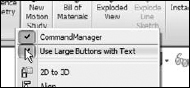
Next, add some toolbars to CommandManager, as follows:
- RMB-click the CommandManager tabs and select Customize CommandManager.
- Click (left-click) the New Tab icon at the right end of the CommandManager tabs and select Surfaces, Sheet Metal, and Annotations. Deselect the Sketch tab by right-clicking it and selecting Hide Tab. The new tab icon is shown in Figure 2.46.
FIGURE 2.46 Adding tabs to the CommandManager

- In the Customize dialog box, select the Large Icons option.
- Turn the Sketch toolbar on, but not inside the CommandManager; use the Toolbars tab of the Customize dialog box. Dock the Sketch toolbar to the right side of the window.
- Select the Standard Views toolbar and drag it to the right end of the CommandManager. Now drag a couple of buttons off it, such as the bottom, or left, or back views.
- On the Commands tab of the Customize dialog box, select the Flyout toolbars entry, and drag any Flyout toolbars from the Customize dialog box to the Menu Bar toolbar. Figure 2.47 shows this step in action.
FIGURE 2.47 Adding flyouts to the Menu Bar toolbar

- With the Commands tab of the Customize dialog box still active, click on the View Category.
- Add or remove tools until this toolbar has the tools you want to use on it. If you want to deselect the Heads-UP View toolbar, activate the Toolbars tab in Customize, and deselect the View (Heads-Up) option.
- Run your cursor over the main menu flyout and use the pushpin to pin the menu open.
- Choose Tools Customize Options and select both Show All buttons for Shortcut customization and Menu customizations. This removes the double arrows at the bottoms of RMB menus. This setting is shown in Figure 2.48.
- While still in the Customize dialog box, change to the Toolbars tab and deselect the Context Toolbar Settings Show In Shortcut Menu option to disable the right-click context toolbar to put the RMB menus back to their pre-2008 state (all entries in menu use text).
- Click and drag the PropertyManager tab (second tab from the left) from the FeatureManager, and dock it just to the right of the FeatureManager under the CommandManager tabs. The display should now look like Figure 2.49.
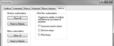
FIGURE 2.49 The customized SolidWorks interface
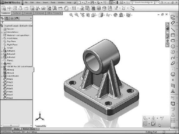
The small flyout in the lower-right corner of Figure 2.49 is the remainder of the Sketch toolbar that does not fit on the screen. This screen shot was taken on a monitor with large icons at 1024 × 768 resolution. At such a low resolution, long toolbars do not fit on the screen, and the remaining icons are activated by the two small arrows at the end of the toolbar.
Customizing menus
If you always do the same types of work, or more importantly, never do certain types of work, you might consider customizing some menus to remove items that you never use. Customization applies to both the main drop-down menus and the context-sensitive RMB menus. To customize a menu, follow these steps:
- Choose Insert Customize Menu with a part document open. Note that Customize Menu is different from Customize.
- Deselect the menu items Sketch from Drawing, DXF/DWG, Object, and Hyperlink (see Figure 2.50). Click anywhere outside the list to close it.
- Click on the Insert menu to ensure that the deselected items have been removed.
FIGURE 2.50 Customizing the Insert menu
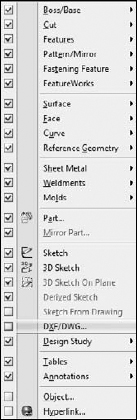
- RMB-click the Right plane in the FeatureManager.
- Select Customize Menu.
- Deselect Section View. Click anywhere outside the list to close it.
- RMB-click the Right plane to verify that Section View has been removed.
Changing interface colors
This tutorial does not depend on RealView capabilities, but later work will. To find out whether your computer is RealView capable, check your video card and driver version against the list on the SolidWorks Web site for system requirements. On the main page of the site, follow the link Support ![]() System Requirements
System Requirements ![]() Graphics Card Drivers.
Graphics Card Drivers.
Before starting this tutorial, make sure the RealView icon is disabled. You can deselect RealView by choosing View ![]() Display
Display ![]() RealView Graphics or by using the gold ball toolbar icon on the Heads Up View toolbar.
RealView Graphics or by using the gold ball toolbar icon on the Heads Up View toolbar.
Cross-Reference
For more information on RealView graphics, see Chapter 5.
Edit the colors used in the interface:
- Choose Tools System Options Colors. Make sure the “Plain (Viewport Background color above)” option is selected.
- Change the Viewport Background color, first in the Color Scheme Settings list, to a light gray color, then click OK and make sure the setting was applied.
- Return to the Colors dialog box by choosing Tools System Options Colors, click the Save As Scheme button, and save the color scheme as Plain Gray.
- Now select the Gradient option, and select the top and bottom gradient colors (second and third in the top list). Click OK and see how you like the gradient display. Adjust the colors until you are happy with them.
- Return to the Colors dialog box by choosing Tools System Options Colors, click the Save As Scheme button, and save the color scheme as Gradient. Figure 2.51 shows the Colors dialog box.
- Use the Current color scheme drop-down list at the top to change the color schemes between the newly saved schemes.
Adding hotkeys
For many users, hotkeys are an integral part of the everyday experience of using SolidWorks. You can easily assign hotkeys and manage the assignments by following these steps:
- Choose Tools Customize Keyboard.
- In the Search For text box, type Options.
- Click in the Shortcut column, and type O.
- Click again in the Search For text box, and type Customize.
- Click in the text box next to the Tools Customize entry and press Ctrl+C. Click No to the question of whether you want to reassign the hotkey. Press Ctrl+T instead.
- Click OK to exit the Customize dialog box.
- Press the O key to open the Options tab. Click OK to exit.
- Press Ctrl+T to open the Customize dialog box. Click OK to exit.
- Press Alt+F, and then click the Close button to exit SolidWorks.
FIGURE 2.51 The Colors settings
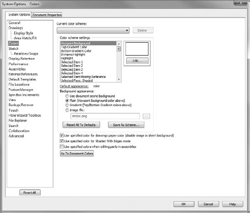
Combining macros with hotkeys
The following steps show you how to link a macro to a hotkey:
On the DVD
You can use the macro called rectangle.swp, located on the DVD.
- Find your SolidWorks installation directory. By default, this directory is C:Program FilesSolidWorks CorpSolidWorks.
- Create a folder called Macros in the SolidWorks directory and put the rectangle.swp macro in it.
- Open SolidWorks.
- Create a new blank part document.
- Press Ctrl+T to access the Customize dialog box.
- Click the Keyboard tab.
- In the Search For text box, type rectangle.
- Click in the Shortcut column next to the listing with the Category of Macros, and press R.
- Click OK to exit the Customize dialog box.
- Press R. The rectangle macro runs and draws a sketch rectangle on the Front plane, centered on the origin.
- Press Ctrl+S to access the Windows standard hotkey for the Save command. Name the part rectangle.sldprt and save it to a workspace directory.
- Press Alt+F and then click Close to exit SolidWorks.
The use of Alt-keys and hotkeys is somewhat exaggerated in this tutorial, but it is intended to get you used to working with them.
Summary
The SolidWorks interface has many elements because SolidWorks has so much functionality. You can access most elements multiple ways, which can be liberating because it offers options, but it also can add to the confusion because there is so much to know. You do not need to know every way to do everything; you only need to know the best way for you. After using this chapter to find the various ways of using the interface, you can develop the way that is most comfortable for you and stick with it.
Be aware that every couple of releases, SolidWorks changes the interface, and often, they use the most radical options available as the new defaults. Keep a copy of your settings file with you, so you can restore settings or take your settings to another computer quickly if you need to re-set up.