Perhaps a bit of history is in order.... When TCP/IP was but a baby, there were two different types of devices with IP addresses, as follows:
![]() End Systems. An end system is essentially to a network what an end user is to computing. An end system is a device that you connect to a network but does not comprise a network device. PC workstations, IP printers, network servers, VoIP phones, VoIP gateways, and so on are considered end systems.
End Systems. An end system is essentially to a network what an end user is to computing. An end system is a device that you connect to a network but does not comprise a network device. PC workstations, IP printers, network servers, VoIP phones, VoIP gateways, and so on are considered end systems.
![]() Intermediate Systems. Perhaps you recognize intermediate systems by their other name: routers. “Ahh!,” you say. No surprise that one of the earliest scalable routing protocols was called IS-IS or Intermediate System–Intermediate System routing.
Intermediate Systems. Perhaps you recognize intermediate systems by their other name: routers. “Ahh!,” you say. No surprise that one of the earliest scalable routing protocols was called IS-IS or Intermediate System–Intermediate System routing.
So, what is an endpoint, then? If you imagine a TCP connection as being a circuit between two devices, using a TCP/IP network for transport, the endpoints are the devices on each end of that circuit. According to Wikipedia:
In computer science, in discussions of communications protocols, an endpoint is the name for the entity on one end of a transport layer connection. In service-oriented architecture, an endpoint is the entry point to a service, a process, or a queue or topic destination.
Securing endpoints in a Cisco Self-Defending Network falls within the category of Cisco Host Security Strategy. There are three prongs to this strategy:
![]() Endpoint Protection (Cisco Security Agent). Detecting and preventing viruses, worms, and trojans from implanting themselves in the network.
Endpoint Protection (Cisco Security Agent). Detecting and preventing viruses, worms, and trojans from implanting themselves in the network.
![]() Cisco Network Admission Control (NAC). Audits endpoint security posture and ensures that only endpoints that comply with the organization’s security policy can access the network.
Cisco Network Admission Control (NAC). Audits endpoint security posture and ensures that only endpoints that comply with the organization’s security policy can access the network.
![]() Network Infection Containment. Mitigates the effect of infections by speeding up the process of identifying infections, isolating affected systems, and cleaning up traffic.
Network Infection Containment. Mitigates the effect of infections by speeding up the process of identifying infections, isolating affected systems, and cleaning up traffic.
What constitutes secure software? In a word, it is its trustworthiness. In Chapter 6, “Introducing Cryptographic Services,” we discovered that one of the important metrics for choosing the ciphers and other elements of a cryptosystem was the trustworthiness of each element. In Cisco’s Host Security Strategy, there are two main software elements that must be secured in order that an endpoint proves its trustworthiness, as follows:
![]() Operating systems
Operating systems
![]() Applications that run in the environment provided by the operating system
Applications that run in the environment provided by the operating system
Because software is often the sole entry point when interfacing with an endpoint, it naturally follows that software is often a primary vector for a variety of attacks that might be leveraged against an endpoint. According to Cisco, the two elements of software—operating systems and applications—have specific vulnerabilities, which if not secured, can lead to exploits. Table 9.1 provides an overview of these software elements, their vulnerabilities and exploits, as well as which Cisco product(s) could be implemented to secure the software system.

Applications and operating systems are susceptible to DoS and access attacks in the same way that network devices are. Some specific attacks that endpoints may be susceptible to include the following:
![]() Buffer Overflows. The conduit through which entry is made to an unsecure system.
Buffer Overflows. The conduit through which entry is made to an unsecure system.
![]() Worms, Viruses, and Trojan Horses. The method or vector in which code is introduced to compromise the unsecure system.
Worms, Viruses, and Trojan Horses. The method or vector in which code is introduced to compromise the unsecure system.
Buffer overflows usually result from a failure to properly validate input data. For example, a web server might be used to accept form data from an Internet user and then pass that data to a database server inside the organization’s network. Even if the communication path between the web server and the database server is secured and inspected for signs of intrusion by systems such as an IPS, these types of attacks are hard to discover. There is frequently nothing untoward in the pattern of data within the packets, and signature-based systems will be ineffective. Thus, to ensure endpoint security, software needs to be deployed on the endpoint to scan for anomalous behavior of the application stack.
Characteristics of a buffer overflow attack include the following:
![]() Input data that contains untested parameters, such as:
Input data that contains untested parameters, such as:
![]() Improperly formatted data.
Improperly formatted data.
![]() Too much data.
Too much data.
![]() Unexpected and improperly formatted control sequences.
Unexpected and improperly formatted control sequences.
![]() Embedded executable code and scripts.
Embedded executable code and scripts.
![]() Not easy to discover and exploit by the hacker community but....
Not easy to discover and exploit by the hacker community but....
![]() When exploit code is discovered or invented by the hacker community, it can be prepackaged for widespread use.
When exploit code is discovered or invented by the hacker community, it can be prepackaged for widespread use.
![]() They generally overwrite memory in an application stack by cramming too much data into an application’s input.
They generally overwrite memory in an application stack by cramming too much data into an application’s input.
The Cisco solution for preventing buffer overflows is Cisco Security Agent. This HIPS product was discussed in some detail in Chapter 8, “Network Security Using Cisco IOS IPS.”
Figure 9.1 illustrates how Cisco Security Agent (CSA) protects the operating system kernel from attack. Referring to Figure 9.1, when an application (step 1) attempts to make a call to the operating system kernel, CSA intercepts this call (step 2). In effect, CSA acts as a firewall in establishing a perimeter between the application and the operating system kernel. Once CSA establishes the trustworthiness of the application, the call is allowed to progress (step 3) to the operating system kernel.

There are two main types of buffer overflows:
![]() Remote exploits
Remote exploits
![]() Local exploits
Local exploits
The most common methods of spreading buffer overflow attacks are the following:
![]() Worms
Worms
![]() Trojan horses
Trojan horses
![]() Viruses
Viruses
![]() Infected spam
Infected spam
EXAM ALERT
According to Cisco (and thus this book), the most common methods of spreading buffer overflows are worms, Trojan horses, viruses, and infected spam. In the real-world that we all live in, however, this is false. Buffer overflows are targeted attacks designed to exploit vulnerabilities in a particular application. Trojan horses and viruses have nothing to do with buffer overflows, but worms and (it’s a stretch) infected spam can be used to inject code, which results in a buffer overflow. In the end, if you are asked on the exam what the most common methods of spreading buffer overflows are, you might have to choose the right wrong answer.
Other characteristics of buffer overflows include the following:
![]() Most common software vulnerability
Most common software vulnerability
![]() Mostly used to root a system or create a DoS attack
Mostly used to root a system or create a DoS attack
NOTE
Rooting a system means to hack a system to become the superuser or root user. This is a UNIX term for someone who possesses the highest level of system privilege.
DoS attacks are not designed to access information, but to make a system unusable. This was discussed in Chapter 1, “Network Insecurity.”
The most common vector of attack for worms, viruses, and Trojan horses is buffer overflows. As previously stated, CSA is Cisco’s product that prevents buffer overflows so logically. CSA is extremely effective in defeating these vectors of attack.
The terms worm, virus, and Trojan horse are often improperly used at best, and are sometimes used interchangeably at worst. Here are accurate, succinct, high-level definitions for these terms:
![]() Worm. Takes its name from burrowing organisms that live in the “soil” of an infected host. The worm replicates, often without any user interaction, into the memory of an infected host that, in turn, infects other computers. Worms have three different parts:
Worm. Takes its name from burrowing organisms that live in the “soil” of an infected host. The worm replicates, often without any user interaction, into the memory of an infected host that, in turn, infects other computers. Worms have three different parts:
![]() The enabling vulnerability (used to worm into the host).
The enabling vulnerability (used to worm into the host).
![]() A propagation mechanism (to replicate and choose additional targets).
A propagation mechanism (to replicate and choose additional targets).
![]() Payload (contains the exploit code; to root the system and gain privileged access, for example).
Payload (contains the exploit code; to root the system and gain privileged access, for example).
![]() Virus. Like microorganisms that invade a human host, viruses attach to other programs and files and execute unwanted functions on that host. Unlike worms, viruses require a careless user’s interaction as their enabler (such as opening an infected email attachment), for their invasion to establish a beachhead on the endpoint.
Virus. Like microorganisms that invade a human host, viruses attach to other programs and files and execute unwanted functions on that host. Unlike worms, viruses require a careless user’s interaction as their enabler (such as opening an infected email attachment), for their invasion to establish a beachhead on the endpoint.
![]() Trojan horse. Like the fabled Trojan horse that fooled the defenders of Troy, a Trojan horse is an application that is written to look like something innocuous, whereas it is actually an attack tool. Trojans are allowed past the defenses by unwitting (or witless!) defenders. Firewalls, for example, are rendered useless by this type of attack.
Trojan horse. Like the fabled Trojan horse that fooled the defenders of Troy, a Trojan horse is an application that is written to look like something innocuous, whereas it is actually an attack tool. Trojans are allowed past the defenses by unwitting (or witless!) defenders. Firewalls, for example, are rendered useless by this type of attack.
Worms have five phases of operation, as follows:
-
Probe. The worm uses various methods such as ping sweeps, and OS and application fingerprinting, to identify vulnerable targets.
-
Penetrate. The exploit code in the worm’s payload is transferred to the host.
-
Persist. The worm drops anchor and sets up shop in memory, installing new code that will survive even if the host is power-cycled.
-
Propagate. Not satisfied with penetrating one host, the worm searches for vulnerabilities on neighbor systems, exploiting the likelihood that these neighbor systems might trust the infected host in order to replicate itself to those other systems. Active TCP connections, file transfers, and file and print sharing are common vectors.
-
Paralyze. After the worm has used the host system to propagate to other systems to ensure its continuing survival, the worm can now paralyze the system that it first penetrated, erasing files, stealing data, and launching DDoS attacks.
Figure 9.2 illustrates these five phases.

As you have probably inferred from the preceding discussion, an Intrusion Protection System would not, by itself, be effective against viruses, worms, and Trojan horses. Many vendors, including Cisco, have products in their security portfolio that are especially effective against such network-borne contagions. We examine three solutions at a high level:
![]() IronPort
IronPort
![]() NAC
NAC
![]() CSA
CSA
IronPort is a recent acquisition by Cisco. IronPort comprises a line of security appliances, deployed at the network perimeter. There are three main series of IronPort security appliances:
![]() C-Series. Email security appliances. These use the same code base as on IronPortSenderBase, an email traffic-monitoring system used by 80% of the largest ISPs.
C-Series. Email security appliances. These use the same code base as on IronPortSenderBase, an email traffic-monitoring system used by 80% of the largest ISPs.
![]() S-Series. Web security appliances. These devices protect against web-borne malware using IronPort’s Web Reputation technology and the Dynamic Vectoring and Streaming™ (DVS) engine.
S-Series. Web security appliances. These devices protect against web-borne malware using IronPort’s Web Reputation technology and the Dynamic Vectoring and Streaming™ (DVS) engine.
![]() M-Series. Security management appliances.
M-Series. Security management appliances.
Network Admission Control has two components, the rather confusingly named NAC Framework and the Cisco NAC Appliance. (Why is the “framework” a component of NAC? Isn’t that backwards? Oh well....)
![]() NAC Framework. Software embedded inside NAC-enabled products, including some Cisco IOS routers. This software acts as an agent and allows the device to collect the bona fides (or “credentials”) of a user or other entity and determine whether they have sufficient privileges to be granted access to the network. These network access devices do not themselves determine whether access privileges should be granted. They forward the credentials to the NAC Appliance. The NAC framework integrates Cisco and other vendors’ NAC-enabled products.
NAC Framework. Software embedded inside NAC-enabled products, including some Cisco IOS routers. This software acts as an agent and allows the device to collect the bona fides (or “credentials”) of a user or other entity and determine whether they have sufficient privileges to be granted access to the network. These network access devices do not themselves determine whether access privileges should be granted. They forward the credentials to the NAC Appliance. The NAC framework integrates Cisco and other vendors’ NAC-enabled products.
![]() Cisco NAC Appliance. Rolls the four key NAC components into a single device. It is a good fit for enterprises that need a simple way to keep track of patch revisions of operating systems, as well as updates for antivirus software and vulnerabilities. Cisco’s NAC Appliance works in a mixed vendor environment and does not need a Cisco network to operate. The four key NAC components are as follows:
Cisco NAC Appliance. Rolls the four key NAC components into a single device. It is a good fit for enterprises that need a simple way to keep track of patch revisions of operating systems, as well as updates for antivirus software and vulnerabilities. Cisco’s NAC Appliance works in a mixed vendor environment and does not need a Cisco network to operate. The four key NAC components are as follows:
![]() Cisco NAC Appliance Server (NAS). A device deployed in-band or out-of-band to perform network access control. As users attempt network access, the user is redirected to the NAS, which checks the device’s compliance. A Cisco IOS router with the right version of Cisco IOS software can perform this function. (See the following Exam Alert for more about using the acronym NAS.)
Cisco NAC Appliance Server (NAS). A device deployed in-band or out-of-band to perform network access control. As users attempt network access, the user is redirected to the NAS, which checks the device’s compliance. A Cisco IOS router with the right version of Cisco IOS software can perform this function. (See the following Exam Alert for more about using the acronym NAS.)
![]() Cisco NAC Appliance Manager (NAM). A GUI-based central administrative interface for IT security personnel. Security policies and users are created and managed. The NAM manages the NAS, with the NAS remaining the device that actually enforces access.
Cisco NAC Appliance Manager (NAM). A GUI-based central administrative interface for IT security personnel. Security policies and users are created and managed. The NAM manages the NAS, with the NAS remaining the device that actually enforces access.
![]() Cisco NAC Appliance Agent (NAA). This is software that resides on a client endpoint. It is queried by NAM to determine an endpoint’s compliance with the network security policy. The endpoint machine is deep-inspected for the following:
Cisco NAC Appliance Agent (NAA). This is software that resides on a client endpoint. It is queried by NAM to determine an endpoint’s compliance with the network security policy. The endpoint machine is deep-inspected for the following:
Registry settings
Services
Files
Required hot fixes for remediation can be determined, as well as the correct version of antivirus software and CSA. From a user’s perspective, this is the interface that they see when they interact with the NAC appliance.
![]() Rule-Set Updates. Quarantined hosts can obtain the latest patches, software revisions, hot fixes, and so on through automatic updates.
Rule-Set Updates. Quarantined hosts can obtain the latest patches, software revisions, hot fixes, and so on through automatic updates.
EXAM ALERT
Don’t you just hate acronyms that are made up of other acronyms! Even worse are acronyms that are reused. We saw “NAS” before in Chapter 3, “Security at the Network Perimeter.” In that context, NAS stood for Network Access Server. Even in the NAC context, a NAS (now a “NAC Appliance Server”) still decides whether an entity is allowed access to the network. They both collect credentials to validate against another device, but unlike AAA where the credentials validate a user’s identity, NAC credentials validate a user’s security posture and determine whether they are sufficient to gain access to the network. No wonder, then, that Cisco prefers to call an AAA NAS an “AAA client.” This terminology is becoming more prevalent.
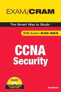
In order to show how all of these components work in practice, Figure 9.3 represents a slight modification of our reference network design. A NAM and NAS have been added to the network in order to manage network admission control (NAC) to the Internet (or a company intranet) for a user.
Figure 9.3 illustrates these three basic steps:
-
A user attempts to access a site on the corporate intranet or on the Internet. The connection attempt is intercepted and blocked by a network device (IOS router in the diagram) until the next steps complete.
-
The user is redirected to a login page, where he is prompted for his login credentials by the NAS. While this occurs, the user’s PC and the network are scanned to determine whether they are compliant to the organization’s security policy.
-
If the device is compliant, it is allowed to connect to the original destination (indicated by the “3A” in Figure 9.3). If the device is noncompliant, the connection is redirected to a quarantine network or sandbox, where remedial action can be taken (indicated by the “3B” in Figure 9.3). The user might be presented with a web page where they download the latest version of the organization’s anti-virus software or invited to reread the organization’s security policy. This network is typically deployed in a separate VLAN.
CSA was covered at a high level in Chapter 8. Take a look at Figure 8.5 of that chapter. You may recall that CSA sits between an application (malicious or not) and the operating system kernel. The question is what type of intelligence is in CSA, which is represented by the padlock in that figure. CSA comprises four interceptors, as follows:
![]() File System Interceptor. All file read/write requests are intercepted and permitted or denied based on the security policy.
File System Interceptor. All file read/write requests are intercepted and permitted or denied based on the security policy.
![]() Network Interceptor. All network read/write requests (network connections) through the NDIS (Network Driver Interface Specification) driver are filtered through the security policy. DoS attacks can be stymied by limiting the number of connections that can be made in a specified period.
Network Interceptor. All network read/write requests (network connections) through the NDIS (Network Driver Interface Specification) driver are filtered through the security policy. DoS attacks can be stymied by limiting the number of connections that can be made in a specified period.
![]() Configuration Interceptor. Read/write requests to the Windows system registry or (in Unix) the run control (rc) files are cleared by the security policy.
Configuration Interceptor. Read/write requests to the Windows system registry or (in Unix) the run control (rc) files are cleared by the security policy.
![]() Execution Space Interceptor. This interceptor ensures that each application plays by the rules by only allowing write access to memory that is owned by that application. It also blocks the injection of arbitrary code in Dynamic Link Libraries (DLLs) and buffer overflows and maintains the integrity of dynamic resources such as memory and network I/O.
Execution Space Interceptor. This interceptor ensures that each application plays by the rules by only allowing write access to memory that is owned by that application. It also blocks the injection of arbitrary code in Dynamic Link Libraries (DLLs) and buffer overflows and maintains the integrity of dynamic resources such as memory and network I/O.
You may have guessed that the interceptors perform functions similar to some of the functions of HIPS and firewalls. Very intuitive! In fact, CSA’s interceptors perform many functions, some of them complimentary. Table 9.2 lists the interceptors and how they correspond to certain high-level security applications

As always, there is the classic tradeoff between usability and security. That said, assume the worst and design for the worst. A reasonable level of paranoia in operating system and application design is not only healthy but strongly encouraged.
Specifically for applications, consider the following best practices:
![]() Make security part of the design and not an afterthought.
Make security part of the design and not an afterthought.
![]() Follow the principle of least privilege.
Follow the principle of least privilege.
![]() Modularize.
Modularize.
![]() Employ practices of secure programming.
Employ practices of secure programming.
![]() Use cryptography where practical against both inside and outside attacks.
Use cryptography where practical against both inside and outside attacks.
![]() Assume data from outside sources is untrustworthy.
Assume data from outside sources is untrustworthy.
![]() Assume that your application users are malicious.
Assume that your application users are malicious.
The following are best practices for operating systems:
![]() Consider using trusted operating systems for critical systems.
Consider using trusted operating systems for critical systems.
![]() Hardening of the operating system remains critical for sensitive environments.
Hardening of the operating system remains critical for sensitive environments.
![]() NAC firewalls are recommended to limit hosts’ exposure.
NAC firewalls are recommended to limit hosts’ exposure.
![]() Other security add-ons are indicated, including integrity checkers and HIPS and host-based firewalls.
Other security add-ons are indicated, including integrity checkers and HIPS and host-based firewalls.
A Storage Area Network (SAN) is a fast and reliable network that provides access to internal and external storage resources. Typically, the intra-SAN traffic does not cross any of the cables of the production network and is usually deployed in its own IP subnet and VLAN for security and performance reasons. Storage devices are shared as peer resources amongst all network servers and are not owned by any one server. A well-designed SAN exemplifies the principle of separation of services.
There are three main benefits of SANs:
![]() Reduced capital and operating expenses.
Reduced capital and operating expenses.
![]() Flexibility and scalability as the business grows and application requirements change.
Flexibility and scalability as the business grows and application requirements change.
![]() Greater reach for replication and backups when compared with storage devices collocated with network servers.
Greater reach for replication and backups when compared with storage devices collocated with network servers.
There are three main SAN interconnection technologies, all based on the Small Computer Systems Interface (SCSI) communications model:
![]() Fiber Channel. This is SCSI over a network infrastructure and has these features:
Fiber Channel. This is SCSI over a network infrastructure and has these features:
![]() Used for host-to-SAN connections.
Used for host-to-SAN connections.
![]() Is the primary transport technology for SANs.
Is the primary transport technology for SANs.
![]() iSCSI (SCSI over TCP/IP). This is SCSI using TCP/IP for transport and has these features:
iSCSI (SCSI over TCP/IP). This is SCSI using TCP/IP for transport and has these features:
![]() Used for host-to-SAN connections.
Used for host-to-SAN connections.
![]() Typically used for implementing SAN connectivity in a LAN environment.
Typically used for implementing SAN connectivity in a LAN environment.
![]() FCIP (Fiber Channel over IP). Used to communicate fiber channel commands over IP and to interconnect SANs:
FCIP (Fiber Channel over IP). Used to communicate fiber channel commands over IP and to interconnect SANs:
![]() SAN-to-SAN connections.
SAN-to-SAN connections.
![]() Typically used in a Metropolitan Area Network (MAN) or WAN.
Typically used in a Metropolitan Area Network (MAN) or WAN.
There are two types of logical addresses implemented within a SAN:
![]() Logical Unit Number (LUN): A 64-bit field that SCSI uses to identify a logically addressable unit of a target within a SCSI device. This address can be masked through a process called LUN masking to hide physical or logical volumes from misbehaving servers but is considered unsecure because these addresses can be spoofed.
Logical Unit Number (LUN): A 64-bit field that SCSI uses to identify a logically addressable unit of a target within a SCSI device. This address can be masked through a process called LUN masking to hide physical or logical volumes from misbehaving servers but is considered unsecure because these addresses can be spoofed.
NOTE
In a SAN, iSCSI volumes will definitely be “targets.” Ugly pun, but you’ll remember the terminology now, right?
![]() World Wide Names (WWN). A 64-bit field used by Fiber Channel to uniquely identify each element on that fiber channel network. Zoning of the fiber switch fabric (similar to VLANs) can use WWNs to assign security permissions, but this is considered unsecure because WWNs are user-configurable. This zoning capability is only possible in a fiber-switched infrastructure and not a simple fiber channel.
World Wide Names (WWN). A 64-bit field used by Fiber Channel to uniquely identify each element on that fiber channel network. Zoning of the fiber switch fabric (similar to VLANs) can use WWNs to assign security permissions, but this is considered unsecure because WWNs are user-configurable. This zoning capability is only possible in a fiber-switched infrastructure and not a simple fiber channel.
Given the relative ease of spoofing both LUNs and WWNs, existing SAN technology cannot be trusted to separate the different SANs’ data planes. With virtual SANs (VSANs):
![]() SAN traffic is isolated by hardware.
SAN traffic is isolated by hardware.
![]() A single switch can be configured with ports in multiple VSANs.
A single switch can be configured with ports in multiple VSANs.
![]() Only ports in the same VSAN can communicate with each other.
Only ports in the same VSAN can communicate with each other.
![]() In a similar fashion to VLANs, a VSAN can span several switches because all the inter-switch traffic is tagged with the VSAN membership info.
In a similar fashion to VLANs, a VSAN can span several switches because all the inter-switch traffic is tagged with the VSAN membership info.
There are six areas to target in securing a SAN, as follows:
![]() SAN Management Access. Secure management services access.
SAN Management Access. Secure management services access.
![]() Fabric Access. Secure access of devices to fiber fabric service.
Fabric Access. Secure access of devices to fiber fabric service.
![]() Target Access. Secure access to LUNs and targets. Can be secured with zoning (see the next section).
Target Access. Secure access to LUNs and targets. Can be secured with zoning (see the next section).
![]() IP Storage Access. iSCSI and FCIP use IP for transport. Secure the underlying IP network. Can be secured with these features in Cisco IOS routers:
IP Storage Access. iSCSI and FCIP use IP for transport. Secure the underlying IP network. Can be secured with these features in Cisco IOS routers:
![]() IPSec VPNs when transiting public carriers.
IPSec VPNs when transiting public carriers.
![]() Hardware-accelerated encryption.
Hardware-accelerated encryption.
![]() Firewall filters.
Firewall filters.
![]() SAN Protocol. Secure FCIP, the switch-to-switch communication protocol.
SAN Protocol. Secure FCIP, the switch-to-switch communication protocol.
![]() Data Integrity and Confidentiality (Secrecy). Secure data that crosses the network, as well as stored on volumes.
Data Integrity and Confidentiality (Secrecy). Secure data that crosses the network, as well as stored on volumes.
NOTE
iSCSI has many similarities to security features that we have examined in previous chapters:
![]() Fiber Channel zones are similar to ACLs.
Fiber Channel zones are similar to ACLs.
![]() Fiber Channel VSANs are similar to VLANs.
Fiber Channel VSANs are similar to VLANs.
![]() Fiber Channel port security is similar to 802.1X port-based authentication.
Fiber Channel port security is similar to 802.1X port-based authentication.
The main strategy for securing access to SAN targets is zoning. We saw zoning a bit earlier in the context of using user-configurable WWNs to place SAN devices in different zones. This is the same idea, but a different context. In fact, zoning to assure target access security is probably most analogous to zones in the Zone-Based Policy Firewall (ZPF) that we introduced in Chapter 5, “Using Cisco IOS Firewalls to Implement a Network Security Policy.”
There are two basic steps, as follows:
-
Associate physical ports on the SAN Fiber switch with VSANs (again, much like a VLAN).
-
Logically divide the VSANs into zones. Zones can be either soft or hard:
![]() Soft Zoning. The visibility of device IDs is restricted, although a server can still connect to a known target using its address.
Soft Zoning. The visibility of device IDs is restricted, although a server can still connect to a known target using its address.
![]() Hard Zoning. More secure than soft zoning. Access to SAN resources is physically controlled across the switch fabric. This is most commonly used.
Hard Zoning. More secure than soft zoning. Access to SAN resources is physically controlled across the switch fabric. This is most commonly used.
Zoning is illustrated in Figure 9.4. Two VSANs are created inside a single physical topology, with each VSAN containing more than one zone. Disks and hosts can exist across multiple zones in a single VSAN but can never span VSANs.

Given that VoIP is another application that uses an IP network, it is also fair to say that many of the best practices that we have discussed in previous chapters will be employed in securing a VoIP network. Before we look at methods of securing a VoIP network, we first look at some basic VoIP terminology. Only then can we examine specific vulnerabilities and the possible exploits that might be leveraged against those vulnerabilities.
In order to understand VoIP security, you should first understand these basic VoIP components and concepts:
![]() IP Phones. Responsible for delivering voice over IP to the desktop.
IP Phones. Responsible for delivering voice over IP to the desktop.
![]() Gatekeeper. Like a traffic cop on a VoIP network. Provides Call Admission Control (CAC), bandwidth management and control, and network address translation.
Gatekeeper. Like a traffic cop on a VoIP network. Provides Call Admission Control (CAC), bandwidth management and control, and network address translation.
![]() Gateway. Translates VoIP to PSTN and vice versa. A gateway also represents a physical connection point for an organization’s local analog and digital voice devices (phones, fax machines, and so on) and Private Branch Exchanges (PBXs).
Gateway. Translates VoIP to PSTN and vice versa. A gateway also represents a physical connection point for an organization’s local analog and digital voice devices (phones, fax machines, and so on) and Private Branch Exchanges (PBXs).
![]() Multipoint Control Unit (MCU). Allows multiple participants in different locations to connect to the same conference call or video conference.
Multipoint Control Unit (MCU). Allows multiple participants in different locations to connect to the same conference call or video conference.
![]() Call Agent. Similar to a proxy, acts as an agent for controlling IP phones, CAC (see Gatekeeper above), bandwidth management and control, and network address translation. Cisco Unified Communications Manager (UCM) and Unified Communications Manager Business Edition serve as call agents.
Call Agent. Similar to a proxy, acts as an agent for controlling IP phones, CAC (see Gatekeeper above), bandwidth management and control, and network address translation. Cisco Unified Communications Manager (UCM) and Unified Communications Manager Business Edition serve as call agents.
![]() Application Servers. These provide extra services such as unified messaging and voice mail. Cisco Unity is an application server.
Application Servers. These provide extra services such as unified messaging and voice mail. Cisco Unity is an application server.
![]() Videoconference Station. Provides an interface to videoconferencing services for an end user. The stations have a camera for video input capture and a microphone for audio, as well as screens and speakers to provide two-way videoconferencing with a remote user.
Videoconference Station. Provides an interface to videoconferencing services for an end user. The stations have a camera for video input capture and a microphone for audio, as well as screens and speakers to provide two-way videoconferencing with a remote user.
Table 9.3 lists and defines some common VoIP protocols.

EXAM ALERT
Memorize these terms, as they will likely be on the exam. Also, although all of these VoIP protocols have their own specific vulnerabilities, SIP has such a large (and growing) installed base that Cisco has chosen SIP alone as an example to analyze shortly in the subsection, “SIP Vulnerabilities.”
Regardless of the VoIP protocol chosen, there are common threats to a VoIP network:
![]() Reconnaissance. Using commonly known reconnaissance techniques to discover the protocols that are being used for the VoIP implementation.
Reconnaissance. Using commonly known reconnaissance techniques to discover the protocols that are being used for the VoIP implementation.
![]() Spam over IP Telephony (SPIT). Not a problem yet, but the fact that we are talking about it means that it might be a future threat. Traditional anti-spam measures (such as IronPort) will not be effective in dealing with this threat. That said, simple measures, such as implementing authentication and TLS (Transport Layer Security), would be effective tools to mitigate its threat.
Spam over IP Telephony (SPIT). Not a problem yet, but the fact that we are talking about it means that it might be a future threat. Traditional anti-spam measures (such as IronPort) will not be effective in dealing with this threat. That said, simple measures, such as implementing authentication and TLS (Transport Layer Security), would be effective tools to mitigate its threat.
![]() DoS Attacks. These fall into three general categories:
DoS Attacks. These fall into three general categories:
![]() Network resource overload. Most commonly uses bandwidth overloading to make a network resource such as a VoIP phone or a call agent unavailable.
Network resource overload. Most commonly uses bandwidth overloading to make a network resource such as a VoIP phone or a call agent unavailable.
![]() Host resource starvation. Using up host resources such that the host can no longer serve legitimate connection requests. A SYN flood is a good example.
Host resource starvation. Using up host resources such that the host can no longer serve legitimate connection requests. A SYN flood is a good example.
![]() Out-of-bounds attacks. The process of creating anomalous data packets with unexpected data that is outside the scope (or bounds) causing system crashes.
Out-of-bounds attacks. The process of creating anomalous data packets with unexpected data that is outside the scope (or bounds) causing system crashes.
![]() Eavesdropping. The unauthorized interception of RTP media streams of VoIP packets for the purpose of accessing confidential information. Can be mitigated simply by using encryption.
Eavesdropping. The unauthorized interception of RTP media streams of VoIP packets for the purpose of accessing confidential information. Can be mitigated simply by using encryption.
![]() Man-in-the-Middle Attacks. Common man-in-the middle attacks such as those discussed in Chapter 1, “Network Insecurity,” could prove to be effective.
Man-in-the-Middle Attacks. Common man-in-the middle attacks such as those discussed in Chapter 1, “Network Insecurity,” could prove to be effective.
The two most common forms of fraud on VoIP networks are the following:
![]() Vishing. Phishing a VoIP network to attempt to compromise confidentiality.
Vishing. Phishing a VoIP network to attempt to compromise confidentiality.
![]() Theft and Toll Fraud. Fraudulently using VoIP services that do not belong to you.
Theft and Toll Fraud. Fraudulently using VoIP services that do not belong to you.
These Cisco Unified Communications Manager (UCM) features can protect the VoIP network against fraud:
![]() Partitioning. Limit phone access to only certain parts of the dial plan.
Partitioning. Limit phone access to only certain parts of the dial plan.
![]() Dial Plans. Filter possibly exploitive phone numbers.
Dial Plans. Filter possibly exploitive phone numbers.
![]() Forced Authorization Codes (FACs). A feature in UCM that can track calls and prevent unauthorized calls in the first place.
Forced Authorization Codes (FACs). A feature in UCM that can track calls and prevent unauthorized calls in the first place.
As mentioned, all VoIP protocols have specific vulnerabilities. SIP is a good example of a protocol whose design did not include security, and as such is a poster child for examining securing VoIP protocols. SIP has very little integral security. It is a relatively immature protocol that is nevertheless seeing widespread adoption. There are three main vulnerabilities with the protocol, as follows:
![]() Registration Hacking. Hackers can intercept incoming calls and spoof the registration server, thus rerouting the calls through themselves. This is similar to an ICMP redirect (see Chapter 1).
Registration Hacking. Hackers can intercept incoming calls and spoof the registration server, thus rerouting the calls through themselves. This is similar to an ICMP redirect (see Chapter 1).
![]() Message Tampering. Because the VoIP messages are carried in cleartext, it is relatively simple for a hacker to alter the VoIP packet contents traveling between SIP endpoints.
Message Tampering. Because the VoIP messages are carried in cleartext, it is relatively simple for a hacker to alter the VoIP packet contents traveling between SIP endpoints.
![]() Session Tear-Down. Allows a hacker to prematurely tear down an existing VoIP session. Similar to an RST attack employed in many IP DoS attacks.
Session Tear-Down. Allows a hacker to prematurely tear down an existing VoIP session. Similar to an RST attack employed in many IP DoS attacks.
These three main vulnerabilities can be mitigated using the techniques and technologies discussed in the next section, “Mitigating VoIP Hacking.”
Although we have only (and briefly) examined specific SIP vulnerabilities, the following techniques can be used to secure any VoIP infrastructure regardless of the protocol employed and will be examined separately:
![]() Voice VLANs (VVLANs)
Voice VLANs (VVLANs)
![]() Firewalls
Firewalls
![]() VPNs
VPNs
![]() Correct VoIP Endpoint Configuration
Correct VoIP Endpoint Configuration
![]() Correct VoIP Server Configuration
Correct VoIP Server Configuration
Recall the concept of separating traffic into different planes. For example, the data plane should be kept separate from the management plane whenever possible. This same discussion holds true for VoIP too. If the VoIP traffic can be separated into a VLAN separate from the data VLAN, it would be much more difficult for a hacker to use a Man-in-the-Middle (MiM) attack or similar to eavesdrop, tamper with, or reconnoiter the VoIP traffic. Figure 9.5 illustrates using separate VLANs for voice and data. A VoIP phone is connected via an IEEE 802.1Q trunk to a Cisco Catalyst switch. A user’s PC is connected to the VoIP phone via the supplied data jack. The switch port in which the VoIP phone is connected is set to trust the VoIP phone’s tagging of its own Ethernet frames with the VLAN number of the Voice VLAN (VVLAN). Other frames, such as those from the PC connected to the VoIP phone, will be tagged for the data VLAN, keeping the data and voice planes separate. This has the further advantage of making Quality of Service (QoS) possible for the VoIP traffic because the VLAN tag makes it simple to identify and allows the QoS-aware switch to apply differentiated, possibly preferential, treatment to the VoIP traffic.

Firewalls such as the Cisco Adaptive Security Appliance (ASA) 5500 Series are an integral part in an overall VoIP security policy. Here are some of the features of Cisco firewalls that you can leverage on in order to increase the security of the VoIP implementation and mitigate some of the common threats that were previously outlined:
![]() Standards Compliance. Ensure that VoIP protocols are standard-compliant and that only SIP methods are sent to UCM.
Standards Compliance. Ensure that VoIP protocols are standard-compliant and that only SIP methods are sent to UCM.
![]() Rate Limiting. Rate limit SIP requests to prevent DoS attacks.
Rate Limiting. Rate limit SIP requests to prevent DoS attacks.
![]() Enforce Call Policies. Create an acceptable use policy of white lists, black lists, SIP URIs, and matching called/caller parties and enforce it.
Enforce Call Policies. Create an acceptable use policy of white lists, black lists, SIP URIs, and matching called/caller parties and enforce it.
![]() Inspection. Firewall dynamically opens TCP and UDP ports for Cisco applications by inspecting the VoIP sessions for this embedded information. Also enable the inspection of encrypted phone calls by the firewall.
Inspection. Firewall dynamically opens TCP and UDP ports for Cisco applications by inspecting the VoIP sessions for this embedded information. Also enable the inspection of encrypted phone calls by the firewall.
![]() Registration. Permit only registered phones to make calls.
Registration. Permit only registered phones to make calls.
As we saw in Chapter 7, “Virtual Private Networks with IPsec,” VPNs seem to be the magic bullet for many issues where network confidentiality, integrity, and authentication are required. For example, an IPsec VPN could be constructed for VoIP-only traffic between two IOS routers acting as gateways. To accomplish this, an ACL specifying which protocols, addresses, port numbers, and so on will be necessary to properly differentiate the VoIP traffic from other site-to-site flows. The use of ACLs and their application to an IPsec crypto map were discussed in Chapter 7. The ACLs that we used in Chapter 7 were not very granular, in that they specified site-to-site flows based solely on IP addresses. These were essentially layer 3-only filters. There are some drawbacks to using an IPsec VPN solution for VoIP, though. Cisco points out that the more specific filtering for which traffic should be transported inside an IPsec VPN (such as would be needed for VoIP flows) should only be used if necessary, because this more granular filtering is more CPU-intensive.
Another caveat in using IPsec VPNs with VoIP is in the area of quality of service (QoS). The VoIP endpoint or server will definitely map the bits in the ToS (Type of Service) byte of the IP header in attempt to express its requirement for QoS on the network. This process is called marking. The IPsec VPN solution must find a way to map these bits into the unencrypted IP packet header, such that QoS-aware devices that are intermediate to the VoIP devices can properly honor the QoS marking of VoIP systems, and thus preserve end-to-end QoS in the network, even over the VPN.
NOTE
Be careful when you implement VoIP inside a VPN across a large public network such as the Internet. QoS is impossible to maintain end-to-end over the Internet because we have no control over the routers that will be forwarding the packets. This makes VoIP over the Internet somewhat problematic since QoS is traditionally a big issue with VoIP in general. An optimum solution would be a VPN constructed over a service provider’s network where the service provider is required to maintain a certain level of service as stipulated in a service level agreement (SLA).
Careful configuration of the VoIP telephone endpoints will go a long way to creating a secure VoIP network. Password protecting or disabling the ability to configure the device altogether by the user is a good first step. The following are other things you may consider:
![]() Firmware. Make sure that only firmware digitally signed by the manufacturer is installed on the devices. (Digital signatures and HMACs are covered in Chapter 6, “Introducing Cryptographic Services.”)
Firmware. Make sure that only firmware digitally signed by the manufacturer is installed on the devices. (Digital signatures and HMACs are covered in Chapter 6, “Introducing Cryptographic Services.”)
![]() Configuration files. Use only signed configuration files.
Configuration files. Use only signed configuration files.
![]() Disable unnecessary features. Disable the following features if they are not needed. (Remember the principle of least privileges.):
Disable unnecessary features. Disable the following features if they are not needed. (Remember the principle of least privileges.):
![]() PC port
PC port
![]() Setting button
Setting button
![]() Speakerphone
Speakerphone
![]() WWW access
WWW access
Using a Cisco solution that includes the Unified Communications Manager means that several security features will be built in, as follows:
![]() File system and OS applications are inaccessible.
File system and OS applications are inaccessible.
![]() Only images digitally signed by Cisco are installable.
Only images digitally signed by Cisco are installable.
![]() The device follows best practices for hardening including:
The device follows best practices for hardening including:
![]() Unused services are removed, and defaults such as usernames are disabled.
Unused services are removed, and defaults such as usernames are disabled.
![]() UCM is constantly improved over time as new threats are discovered.
UCM is constantly improved over time as new threats are discovered.
![]() UCM logs security events.
UCM logs security events.
![]() CSA is enabled on UCM by default.
CSA is enabled on UCM by default.