
In this section, we examine the fundamentals of IPS and IDS technologies, as well as ways to categorize them. We determine where they fit into Cisco’s Self-Defending Network and introduce some exemplary solutions in Cisco’s product portfolio. We conclude with some introductory comments about the Cisco IOS IPS router solution in order to set up for the next section, which concentrates on features of the Cisco IOS IPS.
It’s simple, right? Intrusion Detection Systems (IDSs) monitor for signs of intrusion but do not take action, but Intrusion Prevention Systems (IPSs) monitor for signs of intrusion and take action, right? Actually . . . not! Some vendors make this distinction, but Cisco does not. The following is a high-level description of Cisco’s definition of what constitutes an IDS or IPS:
![]() IDS. According to Cisco, an IDS works offline to the data stream going through the network, analyzing copies of the traffic instead of forcing the data to flow through it. Specifically:
IDS. According to Cisco, an IDS works offline to the data stream going through the network, analyzing copies of the traffic instead of forcing the data to flow through it. Specifically:
![]() Monitors copies of the data flow.
Monitors copies of the data flow.
![]() Does not impede network traffic.
Does not impede network traffic.
![]() Allows some traffic deemed malicious to enter or leave the network.
Allows some traffic deemed malicious to enter or leave the network.
![]() IPS. An IPS places itself in the data stream, thus seeing all the traffic that goes through that part of the network. Specifically:
IPS. An IPS places itself in the data stream, thus seeing all the traffic that goes through that part of the network. Specifically:
![]() Monitors traffic and content from layers 2 through 7 in real-time.
Monitors traffic and content from layers 2 through 7 in real-time.
![]() Must be capable of handling all ingress and egress traffic where it is deployed.
Must be capable of handling all ingress and egress traffic where it is deployed.
![]() Prevents traffic deemed malicious from entering or leaving the network.
Prevents traffic deemed malicious from entering or leaving the network.
Fundamentally, both an IDS and IPS monitor for signs of intrusion but because an IDS take copies of traffic from a data flow, it might miss trigger packets or single-packet attacks. A trigger packet is the very first packet in a malicious data flow. That aside, IDSs and IPSs are complementary in function and have their own strengths and weaknesses. An IDS will often require assistance from other devices such as routers or firewalls to perform the actions dictated by the security policy for the malicious traffic. As we will see, IDS/IPS systems can be deployed as a hardware or software solution depending on the requirement and can be deployed in a number of different solutions; an IDS/IPS can be:
![]() A separate network device
A separate network device
![]() An option card in a router or security appliance
An option card in a router or security appliance
![]() Integral software (as with the Cisco IOS IPS, pictured in Figure 8.1)
Integral software (as with the Cisco IOS IPS, pictured in Figure 8.1)

As shown in Figure 8.1, where you deploy the system and how you configure it will determine whether it is an IDS or IPS. Here are some examples of Cisco IDS and IPS technologies:
![]() The AIP-SSM card can be configured on a Cisco ASA 5500 Series security appliance in either promiscuous (IDS) or inline (IPS) mode.
The AIP-SSM card can be configured on a Cisco ASA 5500 Series security appliance in either promiscuous (IDS) or inline (IPS) mode.
![]() Cisco IOS IPS is configured as a process on a Cisco IOS router.
Cisco IOS IPS is configured as a process on a Cisco IOS router.
![]() Cisco has a whole product line of rackmount IPS appliances that can be physically implemented in line with the network traffic or configured to look at copies of the traffic only.
Cisco has a whole product line of rackmount IPS appliances that can be physically implemented in line with the network traffic or configured to look at copies of the traffic only.
![]() Software deployed on an IP host such as an application server or a client workstation.
Software deployed on an IP host such as an application server or a client workstation.
Note
IDS and IPS technology is called a sensor. IDS and IPS technologies use policy-based rules called signatures to detect intrusions.
Where you deploy IDS and IPS technologies will dictate what they can see and how they can deal with intrusion attempts (and how quickly). You can deploy them in two places:
![]() In the network. Called network IDS and network IPS.
In the network. Called network IDS and network IPS.
![]() On a host. Host-based IPS or HIPS.
On a host. Host-based IPS or HIPS.
In Figure 8.2, an attacker on the Internet launches a hack on the public HTTP server deployed in the DMZ.

As indicated in Figure 8.2, this attack might be missed by a network IDS because it is not deployed inline with the ingress packets to the network and will probably not be able to react to the trigger packet of the attack The following steps illustrate this logic. The numbers in the list refer to the labels in Figure 8.2:
-
The trigger packet of the attack arrives on the IOS firewall.
-
The router is configured to work with a network IDS. One packet is sent to the HTTP server in the DMZ and a copy is sent to the IDS, which is on a separate VLAN.
-
The packet arrives relatively simultaneously on both the server in the DMZ and the network IDS. The IDS recognizes that an attack is taking place.
-
(not pictured) The IDS tells the IOS firewall to block the attack and logs the attack via syslog or SDEE (see the following notes) messages to the MARS appliance.
Note
If you haven’t heard about Cisco Security Monitoring Analysis and Reporting System (MARS) yet, you may want to read a description of MARS in Chapter 4, “Implementing Secure Management and Hardening the Router.” MARS is also mentioned in Chapter 1, “Network Insecurity,” and is referenced in Table 8.3.
Note
The network design in Figure 8.2 should look familiar. It is essentially the same as the reference design in Figure 5.1 from Chapter 5, “Using Cisco IOS Firewalls to Implement a Network Security Policy,” with the addition of a new VLAN where the IDS resides. As mentioned in that chapter, the IOS firewall is capable of performing deep packet inspection and can mitigate a number of network-borne attacks, although this isn’t discussed until another Cisco CCSP course, SNRS.
SDEE (Security Device Event Exchange) protocol is discussed later on in this chapter of the Exam Cram.
Exam Alert
Table 8.1 presents an overview of the relative pros and cons of IDS and IPS. Memorize this table—it’s just the kind of thing that will be on the exam.

Exam Alert
Table 8.2 presents a broad overview of sensor types as well as their relative pros and cons. Memorize it for the exam.

Note
Do not infer from Table 8.2 that anomaly-based IDS/IPS sensors are easy to maintain. Yes, the initial configuration is no more complicated than a signature-based sensor, but much ongoing analysis and reconfiguration of what constitutes normal traffic patterns is required for them to be effective. One thing many enterprises have no real data for is what normal network activity actually is.
Note
A honey pot is a system that you have deployed in your network security architecture with the specific purpose to attract bees. A honey pot is an excellent place to analyze intrusion attempts to your network, and they are often used in conjunction with more mainstream technical solutions, such as Cisco IDS sensors. You must be careful how you deploy them in a legal context, too. Some legal jurisdictions may declare evidence of intrusion attempts on a honey pot as inadmissible for prosecution because of the fine line between enticement and entrapment. Enticement means that you have made it easier for the bees (the attackers) to conduct their normal activity, whereas entrapment means that you have coerced the bees into conducting an activity to which they are not normally predisposed. We’ll let the lawyers argue over that one! See the “Law and Ethics” section in Chapter 1 for more information about the legal framework.
Putting the terms together, an example solution might be a network IPS that uses signatures and policies to detect and block attacks. This leads to the next question, which is: “What response and monitoring actions can be employed by IPS technologies?”
Note
From this point forward, we will focus on IPS technologies (thus the name of the chapter!) and the term IDS will hardly be breathed. This is mainly because the term IDS is falling somewhat out of favor, and IPS is often used interchangeably, though often incorrectly. Besides, what will sell more boxes, an intrusion detection system or an intrusion protection system?!
Exam Alert
So, what are you going to do about that attempted network compromise or intrusion attempt? What response and monitoring actions can be employed by an IPS? Memorize the following list! You may also want to review the theory of TCP sessions found in Chapter 5 before looking at some of these actions.
What follows is a list of some of the actions that we can configure on Cisco sensors:
![]() Deny Attacker Inline. Terminates current packet and shuns all subsequent packets from this attacker for a specified time period, regardless of whether they are part of new TCP connections.
Deny Attacker Inline. Terminates current packet and shuns all subsequent packets from this attacker for a specified time period, regardless of whether they are part of new TCP connections.
![]() Deny Connection Inline. Terminates current and future packets in a specific TCP connection.
Deny Connection Inline. Terminates current and future packets in a specific TCP connection.
![]() Deny Packet Inline. Terminates the packet only.
Deny Packet Inline. Terminates the packet only.
![]() Log Attacker Packets. Logs all packets with an attacker’s IP address.
Log Attacker Packets. Logs all packets with an attacker’s IP address.
![]() Log Pair Packets. Logs events in an attack pair that contains the attacker and victim address pair. This is useful for identifying specific flows.
Log Pair Packets. Logs events in an attack pair that contains the attacker and victim address pair. This is useful for identifying specific flows.
![]() Log Victim Packets. Logs all packets with a victim’s IP address.
Log Victim Packets. Logs all packets with a victim’s IP address.
![]() Produce Alert. Sends an alert to the Event Store (internal log buffer).
Produce Alert. Sends an alert to the Event Store (internal log buffer).
![]() Produce Verbose Alert. Sends an encoded dump (capture) of the offending packet in the alert.
Produce Verbose Alert. Sends an encoded dump (capture) of the offending packet in the alert.
![]() Request Block Connection. Sends a request to another device (router, switch, firewall) to block this connection.
Request Block Connection. Sends a request to another device (router, switch, firewall) to block this connection.
![]() Request Block Host. Sends a request to another device (router, switch, firewall) to block this attacker.
Request Block Host. Sends a request to another device (router, switch, firewall) to block this attacker.
![]() Request SNMP Trap. Instructs the sensor to send an SNMP trap.
Request SNMP Trap. Instructs the sensor to send an SNMP trap.
![]() Reset TCP Connection. Sends TCP RSTs to terminate the TCP connection.
Reset TCP Connection. Sends TCP RSTs to terminate the TCP connection.
Note
Every action that contains the words “log,” “produce,” or “SNMP” sends an alert to the Event Store (internal log buffer), regardless of whether Produce Alert is also selected as an action. This makes sense because they are all essentially alerting type of actions, even if they aren’t called that.
Some actions can be combined. For example, the Deny Packet and Deny Flow actions do not reset the connection, preferring to silently discard traffic, making the IPS stealthy. If you do want to reset the connection, add the Reset TCP Connection action. Of course, the IPS is no longer invisible to the attacker, possibly provoking them. This said, the organization’s security policy will dictate the action(s) to take.
Back in Chapter 4, we discussed options for secure management and logging, focusing mainly on syslog and SNMP. So, we already have our mind around the concept of sending event-triggered alerts to the various reporting servers in our network. This is handy, because referring to Figure 8.2, the reference network diagram indicates that a MARS (Monitoring, Analysis, and Response System) appliance has been deployed in a separate VLAN inside the Cisco IOS firewall. This section isn’t a discussion about how to log to these servers. It is a discussion of what to log and how to log (management) and real-time monitoring of events as they unfold in the traffic streams through our network. The scale of the solution has to match the scale of the network, both in the number of devices deployed, as well as the volume of traffic that is being moved across the monitored devices. As we have seen, some of those same metrics define whether the IPS is inline to the traffic or not.
We need to know the following:
![]() What is happening in real-time (monitoring)
What is happening in real-time (monitoring)
![]() IPS actions and event information collection (management)
IPS actions and event information collection (management)
![]() Analysis of the archived information (reporting)
Analysis of the archived information (reporting)
Note
A little context is in order. You may recall that in Chapter 4, we discussed how secure management and logging needs to be integrated into the organization’s security policy, and this doesn’t just happen—it takes careful design. It was also pointed out that as much as possible, this traffic should be in a separate plane and preferably should not “cross the cables” of the production network. Similarly, monitoring and management should be OOB (out-of-band) with respect to the data plane, perhaps by putting it in a separate VLAN. Keep this in the back of your mind when you look at some of the subsequent high-level discussion about IPS deployment scenarios and technologies in the remainder of this section.
We will look at and implement the different logging protocol options The next section in this chapter, “Implementing Cisco IOS IPS,” examines and implements the different logging protocol options.
Cisco makes the following points about event management and monitoring:
![]() Management and monitoring comprises two key functions:
Management and monitoring comprises two key functions:
![]() Real-time event monitoring and management
Real-time event monitoring and management
![]() Analysis of the archived event information (reporting)
Analysis of the archived event information (reporting)
![]() Depending on scale, management and monitoring can be deployed on a single server or on separate servers.
Depending on scale, management and monitoring can be deployed on a single server or on separate servers.
![]() Recommended maximum of 25 well-tuned sensors reporting to a single IPS management console (management consoles will be discussed shortly).
Recommended maximum of 25 well-tuned sensors reporting to a single IPS management console (management consoles will be discussed shortly).
Table 8.3 outlines Cisco’s portfolio of IPS management software.
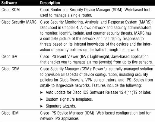
Note
The day after the IINS version 1.0 course was released, Cisco announced a new, freeware IPS management solution called IME (IPS Manager Express). It fully supports the newer 6.x version of the IPS signatures and also has limited support for version 5.x signatures. For more information on Cisco IME, navigate to this link: http://www.cisco.com/en/US/products/ps9610/index.html.
Figure 8.3 illustrates the Threat Analysis Console of the Cisco IPS Event Viewer (IEV)

Recall that IPS technology can be either network- or host-based, although they often co-exist as complementary solutions. With host-based IPS (HIPS), software is deployed right on the application server or client. Cisco’s HIPS solution is the Cisco Security Agent (CSA). Here are some features and recommendations about HIPS:
![]() HIPS audits files systems, OS registries, log files, and system resources.
HIPS audits files systems, OS registries, log files, and system resources.
![]() CSA should be installed on every host that requires HIPS.
CSA should be installed on every host that requires HIPS.
![]() CSA protects the individual host by detecting intrusion attempts.
CSA protects the individual host by detecting intrusion attempts.
![]() CSA does not require special hardware.
CSA does not require special hardware.
![]() Because CSA is behavior-based, it can stop even newer attacks in real-time whose behavior it identifies as malicious.
Because CSA is behavior-based, it can stop even newer attacks in real-time whose behavior it identifies as malicious.
Referring to Figure 8.4, if we installed CSA on the public HTTP server that we first saw in Figure 8.2, it might obviate the need to configure the Cisco IOS firewall as a Network IPS. We could then manage the CSA with the CSA Management Center (CSA MC) on the Systems Administrator workstation. This might work on a small network, but imagine if you have a large network of thousands of IP hosts. You would need to install, configure, and manage all of those CSA instances. Often, CSA is deployed in parts of the network—on critical application servers, for instance—and used to complement Network IPS systems if possible.

Figure 8.5 illustrates how CSA works to protect an IP host from malicious applications directly at the kernel level.

The steps in Figure 8.5 are as follows:
-
An application attempts to call the OS kernel for system resources.
-
The HIPS intercepts this call, and checks it against the policy.
-
The request for system resources is either allowed or denied.
Here are some other points about how HIPS operates:
![]() HIPS intercepts both operating system and application calls.
HIPS intercepts both operating system and application calls.
![]() Rules control application and network protocol stacks.
Rules control application and network protocol stacks.
![]() Processor controls set limits on the following:
Processor controls set limits on the following:
![]() Buffer overflow.
Buffer overflow.
![]() Registry updates.
Registry updates.
![]() Writes to system directory.
Writes to system directory.
![]() Launching of installation programs.
Launching of installation programs.
![]() HIPS is behavior-based.
HIPS is behavior-based.
Table 8.4 outlines the pros and cons of Host Intrusion Prevention Systems (HIPS).

Figure 8.6 illustrates a network IPS deployed on the WAN side of a Cisco IOS firewall. It is deployed in such a way that it will see the inbound traffic (represented as an arrow) from an attacker on the outside. It is an IPS because it is inline with the flow of traffic from the outside. The features of a network IPS are explained more thoroughly next.

Here are some features of a network IPS:
![]() Connected to the network where, if properly deployed, a single sensor can monitor traffic for many hosts or at least a small group of important hosts.
Connected to the network where, if properly deployed, a single sensor can monitor traffic for many hosts or at least a small group of important hosts.
![]() Sensors are appliances with software that is tuned for its role in intrusion detection analysis:
Sensors are appliances with software that is tuned for its role in intrusion detection analysis:
![]() The underlying operating system is hardened.
The underlying operating system is hardened.
![]() Hardware is optimized for intrusion detection analysis.
Hardware is optimized for intrusion detection analysis.
![]() Scalable—networks are easily protected as they grow:
Scalable—networks are easily protected as they grow:
![]() New end system hosts and devices can be added without the need for new sensors (unlike HIPS).
New end system hosts and devices can be added without the need for new sensors (unlike HIPS).
![]() New sensors can be easily added to new or existing networks.
New sensors can be easily added to new or existing networks.
Note
Network IPSs are not necessarily network appliances, although the appliance versions are rack mount blade servers with a hardened version of a Windows Server OS. Also, if you have an extra slot in your Catalyst 6500 series switch, you can add an IDSM-2 module. (see the “Cisco IPS Appliances” section of this chapter). When we implement Cisco IOS IPS using the SDM in the next section, we see that network appliances aren’t Cisco’s only network IPS solution.
Table 8.5 outlines the relative pros and cons of network IPS.

Most of the points in Table 8.6 were already made, but it is useful to summarize them in one place to compare HIPS and network IPS.

Figure 8.7 illustrates Cisco’s portfolio of IPS appliance.

Here is a list of Cisco’s four solutions for IPS appliances:
![]() Cisco IPS 4200 Series Sensors. Standalone rackmount appliance.
Cisco IPS 4200 Series Sensors. Standalone rackmount appliance.
![]() Cisco ASA AIP-SSM. Advanced Inspection and Prevention Security Services Module for the ASA 5500 Series adaptive security appliances.
Cisco ASA AIP-SSM. Advanced Inspection and Prevention Security Services Module for the ASA 5500 Series adaptive security appliances.
![]() Cisco Catalyst 6500 Series IDSM-2. Intrusion Detection System Services Module for the Catalyst 6500 Series switch.
Cisco Catalyst 6500 Series IDSM-2. Intrusion Detection System Services Module for the Catalyst 6500 Series switch.
![]() Cisco IPS AIM. IPS Advanced Integration Module for Cisco 1841, 2800, and 3800 Series Integrated Services routers.
Cisco IPS AIM. IPS Advanced Integration Module for Cisco 1841, 2800, and 3800 Series Integrated Services routers.
All of these devices share the same code as the Cisco IPS 4200 Series IPS appliance. This was not an accident, as Cisco product planners wanted to ensure commonality of the configuration interface (and code base) as networks grow and needs change requiring more and different sensors. This makes it easier for IT security staff to grow with the product.
Note
There is a fifth choice of network IPS, and it is not an appliance. Cisco IOS IPS acts as an inline IPS sensor that can be turned on in Cisco IOS Software router platforms with security feature images. For example, Cisco 800 series Integrated Services routers must have the Advanced IP Services IOS image to enable this feature. We will be examining and configuring the Cisco IOS IPS in the next section, using the Cisco SDM.
IDS and IPS technologies use signatures to detect malicious network activity. This is similar to Anti-X products—virus scanners, for example. A good IPS solution enables you to update the signatures regularly as new threats emerge because the IPS is only as good as the ability of its signatures to detect intrusive activity. Here are the characteristics of IPS signatures:
![]() A network IPS signature is a set of rules used to detect intrusive activity.
A network IPS signature is a set of rules used to detect intrusive activity.
![]() Sensors use signatures to test network packets for signs of known attacks. The signatures have predefined actions to respond to a detected attack.
Sensors use signatures to test network packets for signs of known attacks. The signatures have predefined actions to respond to a detected attack.
![]() When a signature-based IPS is first installed, there will be false positives. You must fine tune the signatures to reduce the frequency of false positives by modifying certain signature parameters.
When a signature-based IPS is first installed, there will be false positives. You must fine tune the signatures to reduce the frequency of false positives by modifying certain signature parameters.
![]() Built-in signatures cannot be added or deleted, although they may be tuned to reduce false positives (see the following note).
Built-in signatures cannot be added or deleted, although they may be tuned to reduce false positives (see the following note).
![]() Some signatures have sub-signatures nested in them. These sub-signatures may be used by other signatures. Changing a sub-signature affects only that sub-signature and not the signature that uses it.
Some signatures have sub-signatures nested in them. These sub-signatures may be used by other signatures. Changing a sub-signature affects only that sub-signature and not the signature that uses it.
Note
Built-in signatures have been removed from Cisco IOS IPS starting from Cisco IOS Software Release 12.4(11)T (reference: http://www.cisco.com/en/US/prod/collateral/iosswrel/ps6537/ps6586/ps6634/prod_qas0900aecd806fc530.html).
Conceptually, signatures are a database of patterns that match attacks. The signatures don’t do anything by themselves, but they are read-in, cached, and parsed by real-time processing daemons called signature micro-engines (SME). A signature micro-engine is a self-contained parallel process that has the following characteristics:
![]() Signature micro-engines support IPS signatures.
Signature micro-engines support IPS signatures.
![]() Signatures that are read into a micro-engine are scanned in parallel for efficiency and maximum throughput.
Signatures that are read into a micro-engine are scanned in parallel for efficiency and maximum throughput.
![]() Micro-engines group a category of signatures.
Micro-engines group a category of signatures.
![]() Each micro-engine is customizable for the protocol and PDU fields that it is designed to inspect.
Each micro-engine is customizable for the protocol and PDU fields that it is designed to inspect.
![]() Micro-engines specify permissible, legal ranges for the items that they are designed to inspect.
Micro-engines specify permissible, legal ranges for the items that they are designed to inspect.
![]() Micro-engines use router memory to compile, load, and merge signatures (see the following note). These signatures use “regular expressions” (REGEXs) for pattern matching. This will be very familiar to readers from the Unix world where REGEXs are quite common in shell scripts. Signatures are customized or written with REGEX. Compiling takes more RAM than the finished signature, so you must be careful to stay within the RAM requirements of your platform for the number of signatures that will be used.
Micro-engines use router memory to compile, load, and merge signatures (see the following note). These signatures use “regular expressions” (REGEXs) for pattern matching. This will be very familiar to readers from the Unix world where REGEXs are quite common in shell scripts. Signatures are customized or written with REGEX. Compiling takes more RAM than the finished signature, so you must be careful to stay within the RAM requirements of your platform for the number of signatures that will be used.
Note
Micro-engines use router memory to compile, load, and merge signatures only when Cisco IOS IPS is used as the IPS is a software process hosted on an IOS router in that case. The four appliances listed previously are self-contained environments with their own flash memory, RAM, and CPUs. It’s not clear whether the exam makes this distinction, so the “right wrong answer” is above.
The third item in the list states that micro-engines group a category of signatures. Table 8.7 shows the list of supported micro-engines and the categories of signatures they group as of Cisco IOS release 12.4(6)T.

Note
Atomic signatures examine simple packets. “Simple” in this context means that the test is simple—for example, an ATOMIC.TCP signature micro-engine provides for simple TCP packet alarms based on source and destination port numbers and flags (SYN, RST, ACK, PSH, URG, FIN). For example, the ATOMIC.TCP SME would be able to analyze a TCP session and reset the session if the two connection partners aren’t playing by the rules. Remember the Reset TCP Connection action in the “IPS Attack Responses” subsection earlier in the chapter?
When a signature is matched due to an attack or a policy violation, the SME in which the signature is compiled will raise an alarm, after which an action is taken to respond. The signature is said to “fire.” The whole efficacy of the IPS solution hinges on the ability of the sensor to react quickly with an IPS action response using the action specified in the signature. Anyone fond of watching Hollywood dramas would quickly state that there are usually more false alarms than there are real ones. In the real world, reacting to false alarms can result in embarrassment, but no real damage is done. If a network IPS blocks legitimate traffic because of a false alarm (a so-called false positive), there might be real damage done to the throughput and quality of service offered by the network. Alarms are either false or true, negative or positive:
![]() False Positive. Normal traffic or a non-malicious action causes the signature to fire.
False Positive. Normal traffic or a non-malicious action causes the signature to fire.
![]() True Positive. An attack is properly detected by the IPS.
True Positive. An attack is properly detected by the IPS.
![]() False Negative. An attack is not detected by the IPS.
False Negative. An attack is not detected by the IPS.
![]() True Negative. Legitimate traffic does not cause signatures to fire.
True Negative. Legitimate traffic does not cause signatures to fire.
Some attacks can cause more damage than others. The alarm severity level assigned to the signature should match the severity of the event. Think of the SMEs as a group of patients vying for the attention of medical doctor, the IPS sensor. The IPS sensor (as well as a real-time monitoring, analysis, and reporting system, such as Cisco Security MARS) should be able to prioritize its responses to the attacks based on the alarms from the SMEs. Signatures should be fired by order of severity, not necessarily in the order in which they are received. The sensor triages the patients, treating the most severely ill first, regardless of when they walked into the emergency room of the hospital.
Here are some general principles with respect to implementing alarms in signatures:
![]() The alarm level assigned to the signature determines the alarm severity level.
The alarm level assigned to the signature determines the alarm severity level.
![]() Alarm severity levels are: informational, low, medium, and high.
Alarm severity levels are: informational, low, medium, and high.
![]() The severity level of the signature should be made to be the same as the severity level of the alarm. (Remember this particularly when you create your own signatures.)
The severity level of the signature should be made to be the same as the severity level of the alarm. (Remember this particularly when you create your own signatures.)
![]() Signatures should be tuned to recognize traffic patterns that are anomalous with respect to your normal network traffic patterns.
Signatures should be tuned to recognize traffic patterns that are anomalous with respect to your normal network traffic patterns.
Here is a summary of the meaning of the four severity levels:
![]() Informational. Activity is not an immediate threat, but the information provided is useful.
Informational. Activity is not an immediate threat, but the information provided is useful.
![]() Low. Activity is not an immediate threat, but anomalous network activity could be perceived as malicious.
Low. Activity is not an immediate threat, but anomalous network activity could be perceived as malicious.
![]() Medium. Activity is likely an immediate threat, and the anomalous network activity is likely malicious.
Medium. Activity is likely an immediate threat, and the anomalous network activity is likely malicious.
![]() High. An immediate threat is extremely likely, and an access or DoS attack has been detected.
High. An immediate threat is extremely likely, and an access or DoS attack has been detected.
The following list of best practices is most appropriate in the context of a large network with multiple IPS sensors. Some of these ideas will be familiar to anyone who has had to set up a deployment of new code to client workstations within a large LAN domain. Even the bandwidth of a modern, high-speed Gigabit Ethernet core can be severely strained if some intelligent design is not employed when updating several devices simultaneously. From a security perspective, it makes good sense to perform your updates separate from the data plane of the production network, using the management network. To summarize:
![]() Set the sensors to automatically update their signature packs instead of doing a manual upgrade of individual sensors.
Set the sensors to automatically update their signature packs instead of doing a manual upgrade of individual sensors.
![]() Employ a dedicated FTP server in the management network from which the sensors can fetch the signature packs.
Employ a dedicated FTP server in the management network from which the sensors can fetch the signature packs.
![]() Stagger the time of day for checking and downloading of the signature packs to prevent over-taxing network resources.
Stagger the time of day for checking and downloading of the signature packs to prevent over-taxing network resources.
![]() Make the deployment of updates simpler by grouping IPS sensors together in a few larger profiles.
Make the deployment of updates simpler by grouping IPS sensors together in a few larger profiles.
Figure 8.8 shows Autoupdate enabled in the Cisco SDM for an IOS IPS configuration. Note that in this example, autoupdate is set up to fetch the signature packs from a Trivial File Transfer Protocol (TFTP) server.

In this section, we introduce the Cisco IOS IPS router solution and walk through a complete configuration using the Cisco SDM. We will also look at logging options available and methods in both the SDM and the CLI to verify the configuration.
Cisco states that the Cisco IOS IPS is an inline network IPS. Actually, it’s a bit redundant saying this, since we have established that whether a device is inline to the traffic or analyzes copies of the traffic offline is what marks the difference between IPS and IDS technology in the first place. Regardless, one of the advantages of having the IPS run on the router is that, unlike IPS deployments where the sensor and the router are separate and must be configured to cooperate with one another, the IPS logic is integral to the router and can leverage on the router’s firewall to take response actions to intrusions. We covered the various response actions in the last section.
Cisco IOS IPS blends features from the Cisco IPS 4200 Series of sensors, as well as the IDSM module for the Cisco Catalyst 6500 Series of switches. It uses three main detection technologies:
![]() Profile-based
Profile-based
![]() Signature-based
Signature-based
![]() Protocol analysis-based
Protocol analysis-based
The first two were discussed in the last section. The third was not and bears some discussion. Protocol analysis-based technology simply means that the IPS analyzes the complete structure of the IP packets and their layer 4 through 7 payload to look for suspicious or abnormal activity. If this analysis was based solely on the protocols’ standards, a lot of traffic would be flagged as anomalous. Instead, this is the Cisco IOS IPS signatures common practice rather than some ideal, reflecting the fact that many protocols violate standards in some fashion.
Cisco specifies the following benefits for the IOS IPS:
![]() Attack Signatures. Over 2,000 are supported, using a common database across Cisco IPS appliances.
Attack Signatures. Over 2,000 are supported, using a common database across Cisco IPS appliances.
![]() Management Tool Support. Supported by Cisco SDM, Cisco Security MARS, Cisco Security Manager, and Cisco IEV.
Management Tool Support. Supported by Cisco SDM, Cisco Security MARS, Cisco Security Manager, and Cisco IEV.
![]() Cisco Self-Defending Network. Integrates into a Self-Defending Network made up of Cisco IPS, Cisco IOS Firewall, Cisco VPN, and Cisco NAC solutions.
Cisco Self-Defending Network. Integrates into a Self-Defending Network made up of Cisco IPS, Cisco IOS Firewall, Cisco VPN, and Cisco NAC solutions.
![]() Inline IPS. All inbound and outbound traffic has to flow through the IPS, meaning that malicious traffic can be detected both inside and outside the network.
Inline IPS. All inbound and outbound traffic has to flow through the IPS, meaning that malicious traffic can be detected both inside and outside the network.
![]() Multi-Threat Detection. Easily integrates into existing network infrastructure to protect against threats to network infrastructure, servers, and other endpoints.
Multi-Threat Detection. Easily integrates into existing network infrastructure to protect against threats to network infrastructure, servers, and other endpoints.
![]() Router Integration. Cisco IOS IPS’s use of the underlying router infrastructure adds an extra layer of security.
Router Integration. Cisco IOS IPS’s use of the underlying router infrastructure adds an extra layer of security.
As stated, the Cisco IOS IPS borrows heavily from the Cisco IPS 4200 Series of sensors and Catalyst 6500 IDSM IPS modules. Table 8.8 shows the features of the signatures in the Cisco IOS IPS.

We configure the Cisco IOS IPS using the Cisco SDM, starting with an IOS router with no IPS configuration on it.
Note
There’s no requirement that the IOS IPS work in conjunction with either CBAC (Cisco IOS classic firewall) or the newer Zone-Based Policy Firewall (ZPF), both of which were discussed in Chapter 5, “Using Cisco IOS Firewalls to Implement a Network Security Policy.” The Cisco IOS IPS could simply be added to basic router functionality on the edge of the network for network designers that subscribe to the separation of services philosophy, with a firewall configured with Cisco ZPF establishing a separate, inner perimeter.
Figure 8.9 illustrates the Cisco SDM home page, indicating an unconfigured IOS IPS.

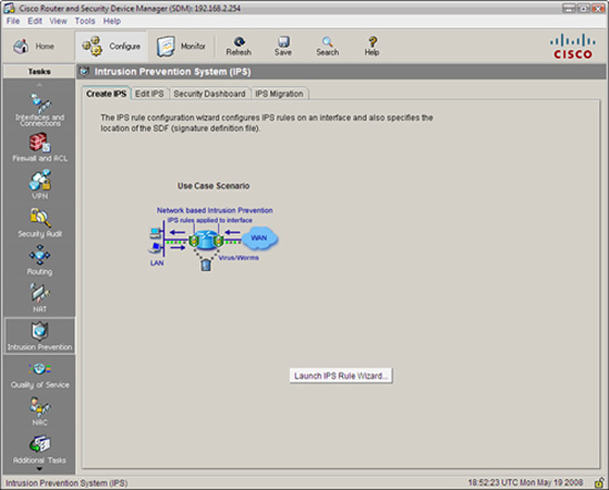
Figure 8.10 illustrates the SDM Configure->Intrusion Prevention System (IPS) window.

Before we start configuring the IPS, let’s look at some of the choices we have when we navigate to Configure->Intrusion Prevention from the home page in the Cisco SDM, as indicated in Figure 8.10. Along the top of the Intrusion Prevention System (IPS) window are these choices, presented as tabs:
![]() Create IPS. Contains a single choice—the IPS Rule wizard (see the following note) used to automate the creation of a Cisco IOS IPS rule and all facets of configuring the IPS.
Create IPS. Contains a single choice—the IPS Rule wizard (see the following note) used to automate the creation of a Cisco IOS IPS rule and all facets of configuring the IPS.
![]() Edit IPS. Enables you to manually edit Cisco IOS IPS rules and either associate or disassociate them from interfaces.
Edit IPS. Enables you to manually edit Cisco IOS IPS rules and either associate or disassociate them from interfaces.
![]() Security Dashboard. Enables you to view Cisco’s Top Threat table and deploy signatures to counter those threats.
Security Dashboard. Enables you to view Cisco’s Top Threat table and deploy signatures to counter those threats.
![]() IPS Migration. This is used to migrate IOS IPS configurations, which were created in earlier versions of the Cisco IOS software. You must be running IOS Software Release 12.4(11)T or later to use this function.
IPS Migration. This is used to migrate IOS IPS configurations, which were created in earlier versions of the Cisco IOS software. You must be running IOS Software Release 12.4(11)T or later to use this function.
There is also the Launch IPS Rule Wizard button that (although you really want to press it now!) we will look at shortly.
Note
Substitute the words “IPS signature configuration” for “IPS rule configuration” every time you see it in the SDM. In some of the dialogs, SDM calls signatures “rules.” This is inconsistent use of the word “rule” because the Launch IPS Rule Wizard button (see Figure 8.10, as well as the previous paragraph) does not launch a wizard where you can change the signatures! The word “rule” in that context means policy. Ouch!
While we’re on the subject, sharp-eyed readers will notice that the SDM wizard is called the Intrusion Prevention System wizard, whereas we have been calling it the Intrusion Protection System up to now. This is just semantics, and you shouldn’t read anything into the difference because they actually mean the same thing. Just when you thought you were figuring out the terminology!
The reference diagram for configuring Cisco IOS IPS is found in Figure 8.11. It is a slight modification to the reference diagram found in Figure 8.6 that we have been using in this chapter. The management VLAN is VLAN 3. The production VLAN is VLAN 1. This is where the wired workstations reside that belong to our internal knowledge workers. Similarly, there is a separate VLAN, VLAN 99, deployed for our wireless hotspot. Essentially, all three of these VLANs represent internal networks for the purpose of configuring the IOS IPS. FastEthernet 4 is the external, Internet-facing interface.

Because there is currently no IPS configured, we follow these steps to configure the Cisco IOS IPS:
-
Navigate to Configure->Intrusion Prevention->Create IPS. The screen that appears is illustrated in Figure 8.12.
-
Push the Launch IPS Rule Wizard button.
-
If this is a first-time configuration, an information window appears, indicating that “SDM will open a subscription with the router to get the SDEE events.” Press OK.
-
The Welcome to the IPS Policies Wizard screen appears. Click Next. The Select Interfaces screen opens and is illustrated in Figure 8.13.
-
Place a check mark beside each interface in the check box corresponding to the direction, Inbound and Outbound, that you want to inspect the packets for signs of intrusion. In this example, FastEthernet4 is the Internet-facing interface, and Vlan1, Vlan3, and Vlan99 are all inside the perimeter (refer to Figure 8.11).
-
Click Next. The Signature File and Public Key window appears and is illustrated in Figure 8.14.
Note
Recall that there are no built-in signatures as of IOS Software Release 12.4(11)T. Some IOS routers ship from Cisco with .SDF (Signature Definition Files) already in flash memory. Also, when you download and install the SDM, there are SDF files included with the SDM archive for different amounts of RAM that can get you started without having to go to CCO. That said, the latest signature files are available on CCO to users with sufficient access.


![]() Specify the signature file you want to use with the IOS IPS.
Specify the signature file you want to use with the IOS IPS.
![]() Get the latest signature file from Cisco.com and save to PC.
Get the latest signature file from Cisco.com and save to PC.
If you choose the first choice, you will be led through a dialog that enables you to fetch the signature file from one of the following: router flash, the local PC, or the URL of an external source such as a web server.
Note
When fetching the file from your PC, the signature file will be of the form sigv5-SDM-Sxxx.zip, where xxx is the signature set’s version number. If you choose to specify the router’s flash, use the format IOS-Sxxx-CLI.pkg.
If you choose the second choice, you will be prompted for where you want to save the file; you then are prompted for your username and password on CCO and to save the SDF file (in .zip format) to your local PC’s hard drive and subsequently install on the IPS. Incidentally, this will also download the update files in the form of a .pkg file, which you can push to the router (see the preceding note).
In both cases, you must enter the name and value of Cisco’s public key before you proceed. This is because any changes you make to the signatures (so called “deltas”) will need to be signed with this key for security reasons. You must visit this URL to look up both the name of the key to put in the Name field and the key’s value to put in the Key field. The URL is http://www.cisco.com/pcgi-bin/tablebuild.pl/ios-v5sigup.
Enter the values in both fields as indicated; then proceed by clicking Next.
7. The Config Location and Category windows appear as illustrated in Figure 8.15.

You are presented with these options:
![]() Config Location. Specify where the IPS configuration, .pkg files, and delta files are located. This may be in router flash or on an external server such as an HTTP server specified by URL. Follow the prompts.
Config Location. Specify where the IPS configuration, .pkg files, and delta files are located. This may be in router flash or on an external server such as an HTTP server specified by URL. Follow the prompts.
![]() Signature Category.
Signature Category.
![]() Basic. If the router has 128MB or less of flash, Cisco recommends using the Basic category to avoid memory allocation errors.
Basic. If the router has 128MB or less of flash, Cisco recommends using the Basic category to avoid memory allocation errors.
![]() Advanced. If the router has more than 256MB of flash, you may choose the Advanced category.
Advanced. If the router has more than 256MB of flash, you may choose the Advanced category.
Note
The Cisco IINS v1.0 courseware that was referenced for this Exam Cram specifies that Basic is recommended for 128MB or less of flash memory vs. RAM. This isn’t correct (and doesn’t make sense). This URL at Cisco indicates otherwise. Remember, though, that what’s in the course is always the right wrong answer! (http://www.cisco.com/en/US/prod/collateral/iosswrel/ps6537/ps6586/ps6634/prod_white_paper0900aecd8066d265.html)
8. Click Next when you have filled out the information per the previous step. The Summary window of the IPS Policies Wizard appears. This is illustrated in Figure 8.16.

9. Review the information in the window; then click Finish to deliver the configuration to the router. Click OK on the Commands Delivery Status window when this has been completed. The IOS IPS Configuration Status window appears, indicating that the signatures are being configured on the router. This is illustrated in Figure 8.17.

10. After the IPS Configuration has been completed, the Configure> Intrusion Prevention window appears, this time with the Edit IPS tab selected, as illustrated in Figure 8.18. Review the information in this window:

Note
Looking at the bottom of the Edit IPS screen in Figure 8.18 indicates that no filters have been set for the traffic that will be inspected (inbound, in this example) on the interfaces. Thus when you select an interface, the warning “IPS rule is enabled, but there is no filter configured for this rule. IPS will scan all inbound traffic” appears. This can be fine-tuned separately if desired.
When you return to the Cisco SDM home page, the working IPS configuration can be seen as in Figure 8.19.
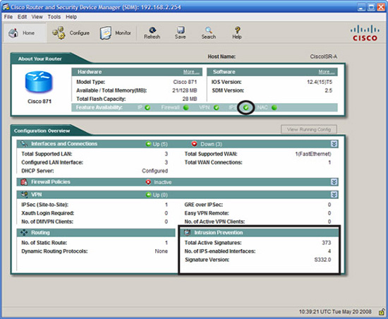
In the right-bottom quadrant of the screenshot in Figure 8.19, we learn the following:
![]() Total Active Signatures: 373. These are the number of signatures that are active out of the total possible signatures in the signature database.
Total Active Signatures: 373. These are the number of signatures that are active out of the total possible signatures in the signature database.
![]() No. of IPS-enabled Interfaces: 4. This makes sense because we enabled IPS on VLANs 1, 3, and 99 and FastEthernet 4 (see Figures 8.11 and 8.13).
No. of IPS-enabled Interfaces: 4. This makes sense because we enabled IPS on VLANs 1, 3, and 99 and FastEthernet 4 (see Figures 8.11 and 8.13).
![]() Signature Version: S332.0. This is the version of the signature file that we downloaded and installed from Cisco.
Signature Version: S332.0. This is the version of the signature file that we downloaded and installed from Cisco.
If you were looking at syslog output (if configured) or you had a terminal window to the CLI open while the IPS was being configured, you might see some interesting output as the micro-engines are being compiled into RAM. First, let’s examine what the %IPS-6-ENGINE message text means in the IPS messages that are displayed to the terminal:
![]() ENGINE_BUILDS_STARTED. Each micro-engine starts the compile process. Recall from the previous section that this part of the process consumes more RAM than is used once the build completes.
ENGINE_BUILDS_STARTED. Each micro-engine starts the compile process. Recall from the previous section that this part of the process consumes more RAM than is used once the build completes.
![]() ENGINE_BUILDING. The micro-engines is in the process of being compiled. Note that this is done consecutively until all the micro-engines that have enabled signatures are compiled into memory.
ENGINE_BUILDING. The micro-engines is in the process of being compiled. Note that this is done consecutively until all the micro-engines that have enabled signatures are compiled into memory.
![]() ENGINE_READY. The compile process for the micro-engine is complete. The next engine starts.
ENGINE_READY. The compile process for the micro-engine is complete. The next engine starts.
Now here is an example of the screen output of an actual terminal session. Note that the term monitor command has been executed to ensure that the terminal windows that we are using will see output that would normally be directed to the default output device, console 0. We would not need to use this command if this output was taken from a terminal connected to console 0. The output represents the 13 signature micro engines (SMEs) compiling signatures and the number of signatures that are being compiled per SME.
CiscoISR-A#terminal monitor
CiscoISR-A#
May 19 20:36:32.906: %IPS-6-ENGINE_BUILDS_STARTED: 20:36:32 UTC May 19 2008
May 19 20:36:32.910: %IPS-6-ENGINE_BUILDING: multi-string - 8 signatures - 1 of 13 engines
May 19 20:36:33.070: %IPS-6-ENGINE_READY: multi-string - build time 160 ms - packets for this engine will be scanned
May 19 20:36:33.086: %IPS-6-ENGINE_BUILDING: service-http - 627 signatures - 2 of 13 engines
May 19 20:36:43.339: %IPS-6-ENGINE_READY: service-http - build time 10256 ms - packets for this engine will be scanned
May 19 20:36:43.363: %IPS-6-ENGINE_BUILDING: string-tcp - 1045 signatures - 3 of 13 engines
May 19 20:36:49.258: %IPS-6-ENGINE_READY: string-tcp - build time 5896 ms - packets for this engine will be scanned
May 19 20:36:49.266: %IPS-6-ENGINE_BUILDING: string-udp - 75 signatures - 4 of 13 engines
May 19 20:36:50.034: %IPS-6-ENGINE_READY: string-udp - build time 764 ms - packets for this engine will be scanned
May 19 20:36:50.038: %IPS-6-ENGINE_BUILDING: state - 28 signatures - 5 of 13 engines
May 19 20:36:50.113: %IPS-6-ENGINE_READY: state - build time 76 ms - pack-ets for this engine will be scanned
May 19 20:36:50.197: %IPS-6-ENGINE_BUILDING: atomic-ip - 287 signatures - 6 of 13 engines
May 19 20:36:52.333: %IPS-6-ENGINE_READY: atomic-ip - build time 2132 ms - packets for this engine will be scanned
May 19 20:36:52.381: %IPS-6-ENGINE_BUILDING: string-icmp - 3 signatures - 7 of 13 engines
May 19 20:36:52.421: %IPS-6-ENGINE_READY: string-icmp - build time 36 ms - packets for this engine will be scanned
May 19 20:36:52.421: %IPS-6-ENGINE_BUILDING: service-ftp - 3 signatures - 8 of 13 engines
May 19 20:36:52.441: %IPS-6-ENGINE_READY: service-ftp - build time 16 ms - packets for this engine will be scanned
May 19 20:36:52.441: %IPS-6-ENGINE_BUILDING: service-rpc - 75 signatures - 9 of 13 engines
May 19 20:36:52.689: %IPS-6-ENGINE_READY: service-rpc - build time 244 ms - packets for this engine will be scanned
May 19 20:36:52.693: %IPS-6-ENGINE_BUILDING: service-dns - 38 signatures - 10 of 13 engines
May 19 20:36:52.773: %IPS-6-ENGINE_READY: service-dns - build time 80 ms - packets for this engine will be scanned
May 19 20:36:52.777: %IPS-6-ENGINE_BUILDING: normalizer - 9 signatures - 11 of 13 engines
May 19 20:36:52.785: %IPS-6-ENGINE_READY: normalizer - build time 4 ms - packets for this engine will be scanned
May 19 20:36:52.785: %IPS-6-ENGINE_BUILDING: service-smb-advanced - 36 signatures - 12 of 13 engines
May 19 20:36:55.512: %IPS-6-ENGINE_READY: service-smb-advanced - build time 2724 ms - packets for this engine will be scanned
May 19 20:36:55.536: %IPS-6-ENGINE_BUILDING: service-msrpc - 27 signatures - 13 of 13 engines
May 19 20:36:55.712: %IPS-6-ENGINE_READY: service-msrpc - build time 164 ms - packets for this engine will be scanned
May 19 20:36:55.720: %IPS-6-ALL_ENGINE_BUILDS_COMPLETE: elapsed time 22820 ms
The highlights in the previous command output indicate the SME that was loaded as well as the number of signatures that have been compiled for each SME. Compare the output with the SME names in Table 8.7.
You can verify that the signatures are loaded by entering the show ip ips signatures count command. The Cisco SDF release version number, the names of the SMEs, and the total number of signatures is highlighted for reference.
CiscoISR-A#show ip ips signatures count
Cisco SDF release version S332.0
Trend SDF release version V0.0
Signature Micro-Engine: multi-string: Total Signatures 8
multi-string enabled signatures: 8
multi-string retired signatures: 3
multi-string compiled signatures: 5
Signature Micro-Engine: service-http: Total Signatures 627
service-http enabled signatures: 130
service-http retired signatures: 525
service-http compiled signatures: 102
service-http obsoleted signatures: 1
Signature Micro-Engine: string-tcp: Total Signatures 1045
string-tcp enabled signatures: 541
string-tcp retired signatures: 950
string-tcp compiled signatures: 95
string-tcpobsoleted signatures: 9
Signature Micro-Engine: string-udp: Total Signatures 75
string-udp enabled signatures: 2
string-udp retired signatures: 54
string-udp compiled signatures: 21
string-udpobsoleted signatures: 1
Signature Micro-Engine: state: Total Signatures 28
state enabled signatures: 15
state retired signatures: 25
state compiled signatures: 3
Signature Micro-Engine: atomic-ip: Total Signatures 287
atomic-ip enabled signatures: 88
atomic-ip retired signatures: 252
atomic-ip compiled signatures: 35
Signature Micro-Engine: string-icmp: Total Signatures 3
string-icmp enabled signatures: 0
string-icmp retired signatures: 1
string-icmp compiled signatures: 2
Signature Micro-Engine: service-ftp: Total Signatures 3
service-ftp enabled signatures: 1
service-ftp retired signatures: 2
service-ftp compiled signatures: 1
Signature Micro-Engine: service-rpc: Total Signatures 75
service-rpc enabled signatures: 44
service-rpc retired signatures: 43
service-rpc compiled signatures: 32
Signature Micro-Engine: service-dns: Total Signatures 38
service-dns enabled signatures: 30
service-dns retired signatures: 9
service-dns compiled signatures: 29
Signature Micro-Engine: normalizer: Total Signatures 9
normalizer enabled signatures: 8
normalizer retired signatures: 1
normalizer compiled signatures: 8
Signature Micro-Engine: service-smb-advanced: Total Signatures 36
service-smb-advanced enabled signatures: 36
service-smb-advanced retired signatures: 1
service-smb-advanced compiled signatures: 35
Signature Micro-Engine: service-msrpc: Total Signatures 27
service-msrpc enabled signatures: 27
service-msrpc retired signatures: 22
service-msrpc compiled signatures: 5
Total Signatures: 2261
Total Enabled Signatures: 930
Total Retired Signatures: 1888
Total Compiled Signatures: 373
Total Obsoleted Signatures: 11
Note
Note that the output of the show ip ips signatures count command shows the signatures organized by micro-engine and in the same order that they were compiled, as was seen in the syslog output.
Here are the basic commands used to configure the IOS IPS with the CLI. We’ll start with an example that matches the worked example that we have just completed with the SDM and then look at the commands one by one and in the order shown (note: the configuration for interfaces Vlan99 and Vlan3 has been omitted):
ip ips config location flash:/ips/ retries 1
ip ips notify SDEE
ip ips name sdm_ips_rule
!
ip ips signature-category
category all
retired true
category ios_ips basic
retired false
!
interface Vlan1
ip ips sdm_ips_rule in
ip virtual-reassembly
!
interface FastEthernet4
ip ips sdm_ips_rule in
ip virtual-reassembly
Here is an explanation of the commands (see the previous configuration for specific examples used in our reference network):
![]() ip ips config location. This global configuration command specifies the location of the IPS configuration. In this example, it is in the flash:/ips/ directory.
ip ips config location. This global configuration command specifies the location of the IPS configuration. In this example, it is in the flash:/ips/ directory.
![]() ip ips notify. This global configuration command specifies the method of event notification. In this example, SDEE is being used.
ip ips notify. This global configuration command specifies the method of event notification. In this example, SDEE is being used.
![]() ip ips name. This global configuration command specifies the IPS rule (policy) name—sdm_ips_rule in this example.
ip ips name. This global configuration command specifies the IPS rule (policy) name—sdm_ips_rule in this example.
![]() ip ips signature-category. This global configuration command configures the router to support the default basic or advanced signature set.
ip ips signature-category. This global configuration command configures the router to support the default basic or advanced signature set.
![]() ip ips ips_rule_name. This interface configuration command applies the named IPS rule (policy) on the selected interface.
ip ips ips_rule_name. This interface configuration command applies the named IPS rule (policy) on the selected interface.
![]() ip virtual-reassembly. This interface configuration command turns on Virtual Fragment Reassembly (VFR). Dynamic ACLs are created to protect the network against various fragmentation attacks.
ip virtual-reassembly. This interface configuration command turns on Virtual Fragment Reassembly (VFR). Dynamic ACLs are created to protect the network against various fragmentation attacks.
This section examines the steps required to configure IPS signatures using the SDM.
You may recall earlier that one of Cisco’s recommendations for IPS best practices is to set the alert level of any signature to the severity level of the signature itself. You can set the severity level of a signature, both the included ones as well as ones you create, by following these steps:
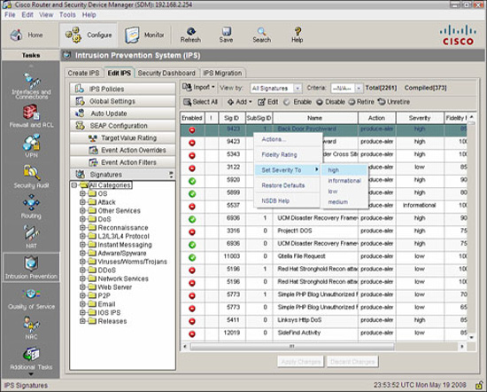
-
From the SDM, navigate to Configure->Intrusion Prevention->Edit IPS->Signatures->All Categories. The list of all signatures appears, as illustrated in Figure 8.20.
-
Select the signature whose severity level you want to change; then right-click to bring up the context menu. Select Set Severity Level to and select from: high, informational, low, or medium. This is illustrated in Figure 8.20
-
Click Apply Changes in the Edit IPS window when you are done.
Recall that IPS signatures have default actions or “responses.” (See the subsection “Signature Attack Responses” for a complete list of responses and their meaning.) The SDM enables you to change these actions. To change the action for a signature, follow these steps (using the Email signature category as an example):
-
From the SDM, navigate to Configure->Intrusion Prevention->Edit IPS->Signatures->Email.
-
Select the signature whose severity level you want to change; then right-click to bring up the context menu. Select Assign Actions from the context menu. A new Assign Actions window appears, as illustrated in Figure 8.21.

3. Place a check mark in the box beside the action(s) you want to take. The actions you can choose from are the following:
![]() Deny Attacker Inline
Deny Attacker Inline
![]() Deny Connection Inline
Deny Connection Inline
![]() Deny Packet Inline
Deny Packet Inline
![]() Produce Alert (the default for this IMAP Email Signature)
Produce Alert (the default for this IMAP Email Signature)
![]() Reset TCP Connection
Reset TCP Connection
5. Click Apply Changes in the Edit IPS window when you are done.
You can edit a signature, both the included ones as well as ones you create, by following these steps. This example will choose a signature from the Reconnaissance category called TCP Ports Sweeps:
-
From the SDM, navigate to Configure->Intrusion Prevention->Edit IPS->Signatures->Reconnaissance->TCP Ports Sweeps.
-
Select the signature you want to edit and click the Edit button.
-
The Edit Signature window appears, as illustrated in Figure 8.22.
The parameters you see depend on the signature. Here’s a list of what you may edit in this window, depending on the signature:
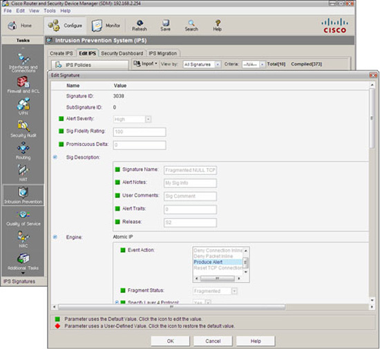
![]() Signature ID. Unique number assigned to each signature.
Signature ID. Unique number assigned to each signature.
![]() SubSignature ID. Unique number assigned to the subsignature. Allows for more granularity of signature definitions.
SubSignature ID. Unique number assigned to the subsignature. Allows for more granularity of signature definitions.
![]() Alert Severity. Defines the severity of alert sent to the sensor when this signature triggers.
Alert Severity. Defines the severity of alert sent to the sensor when this signature triggers.
![]() Sig Description. This is a section where you can give the signature a name, put in user comments, alert notes, alert traits, and release number. Certain of these parameters are pre-defined (though editable) for Cisco signatures.
Sig Description. This is a section where you can give the signature a name, put in user comments, alert notes, alert traits, and release number. Certain of these parameters are pre-defined (though editable) for Cisco signatures.
![]() Engine. Specifies information as to which micro-engine this signature uses.
Engine. Specifies information as to which micro-engine this signature uses.
![]() Event Counter. This is a section where you can define the event count, event count key, and whether a specific alert interval is to be specified (useful for rate-limiting to defend against DoS attacks against the IPS).
Event Counter. This is a section where you can define the event count, event count key, and whether a specific alert interval is to be specified (useful for rate-limiting to defend against DoS attacks against the IPS).
![]() Alert Frequency. Define frequency of the alert.
Alert Frequency. Define frequency of the alert.
![]() Status. This section specifies whether the signature is enabled or disabled and whether or not it is retired.
Status. This section specifies whether the signature is enabled or disabled and whether or not it is retired.
4. Click OK when you are done with the changes.
5. Click Apply Changes in the Edit IPS window when you are done.
The Cisco IOS IPS supports both the Security Device Event Exchange (SDEE) and syslog protocols to send alerts.
Recall that an alarm is generated when an enabled signature is triggered. The alarms are stored in a buffer on the sensor. One disadvantage of syslog is that the syslog server is passive, relying on the sensor to send alerts to it. This is indicated by the arrow in Figure 8.23 pointing to the syslog server from the Cisco IOS IPS. SDEE, on the other hand, is a subscription type of service where hosts can pull alarms from the sensor at any time. This is indicated by the two-headed arrow indicated in Figure 8.23. SDEE-format messages are much richer in their information content.

Here are some other things you need to know about SDEE:
![]() 1,000 events can be stored in the SDEE buffer. 200 is the default. Disabling SDEE notification erases the buffer.
1,000 events can be stored in the SDEE buffer. 200 is the default. Disabling SDEE notification erases the buffer.
![]() Network management applications pull SDEE messages from the IOS IPS.
Network management applications pull SDEE messages from the IOS IPS.
![]() SDEE is evolving as the standard format for security reporting network management.
SDEE is evolving as the standard format for security reporting network management.
![]() SDEE is vendor-independent.
SDEE is vendor-independent.
![]() SDEE uses HTTP or HTTPS (more secure) for transport, thus must be enabled on the router.
SDEE uses HTTP or HTTPS (more secure) for transport, thus must be enabled on the router.
![]() The IOS IPS still sends alerts via syslog.
The IOS IPS still sends alerts via syslog.
Navigate to Monitor->Logging->SDEE Message Log to view the SDEE message log. This dialog is illustrated in Figure 8.24.

Here’s an example of an SDEE message captured in the CLI. The IPS is sending an alert of a possible fragmentation attack since signature 1207 has been triggered:
May 20 12:37:24.723: %IPS-4-SIGNATURE: Sig:1207 Subsig:0 Sev:25 IP
Fragment Too Many Datagrams [192.168.2.119:0 -> 192.168.2.254:0]
RiskRating:25
Navigate to Monitor->Logging->Syslog to view the syslog message log. This dialog is illustrated in Figure 8.25.

This section outlines procedures to verify IOS IPS operation with both the SDM and the CLI.
Navigate to Configure->Intrusion Prevention->Edit IPS to verify that IPS has been enabled on interfaces and in which direction. This is illustrated in Figure 8.26.
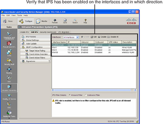
Also note in Figure 8.26 that VFR (Virtual Fragment Reassembly) has been enabled on all of the interfaces. The IOS IPS cannot detect intrusions by examining fragments of IP packets. They must be coalesced so the entire packet can be checked.
Of course, the Edit IPS tab can be used to edit and not just verify the IPS!
The command show ip ips configuration (reviewed previously) can be used to verify a summary of the IPS configuration, including the configured location of the files, name of policies (rules), and which interfaces they have been applied on and in which direction. These are highlighted in the following command output:
CiscoISR-A#show ip ips configuration
IPS Signature File Configuration Status
Configured Config Locations: flash:/ips/
Last signature default load time: 20:36:55 UTC May 19 2008
Last signature delta load time: 20:38:01 UTC May 19 2008
Last event action (SEAP) load time: -none-
General SEAP Config:
Global Deny Timeout: 3600 seconds
Global Overrides Status: Enabled
Global Filters Status: Enabled
IPS Auto Update is not currently configured
IPS Syslog and SDEE Notification Status
Event notification through syslog is enabled
Event notification through SDEE is enabled
IPS Signature Status
Total Active Signatures: 373
Total Inactive Signatures: 1888
IPS Packet Scanning and Interface Status
IPS Rule Configuration
IPS name sdm_ips_rule
IPS fail closed is disabled
IPS deny-action ips-interface is false
Fastpath ips is enabled
Quick run mode is enabled
Interface Configuration
Interface Vlan3
Inbound IPS rule is sdm_ips_rule
Outgoing IPS rule is not set
Interface Vlan1
Inbound IPS rule is sdm_ips_rule
Outgoing IPS rule is not set
Interface FastEthernet4
Inbound IPS rule is sdm_ips_rule
Outgoing IPS rule is not set
Interface Vlan99
Inbound IPS rule is sdm_ips_rule
Outgoing IPS rule is not set
IPS Category CLI Configuration:
Category all:
Retire: True
Category ios_ips basic:
Retire: False
CiscoISR-A#
If you simply want to see which interface(s) the policies (rules) have been applied on, you can use the show ip ips interfaces command. Here we see the SDM-generated IPS policy sdm_ips_rule applied inbound on Vlan1, Vlan3, Vlan99, and FastEthernet 4:
CiscoISR-A#show ip ips interfaces
Interface Configuration
Interface Vlan3
Inbound IPS rule is sdm_ips_rule
Outgoing IPS rule is not set
Interface Vlan1
Inbound IPS rule is sdm_ips_rule
Outgoing IPS rule is not set
Interface FastEthernet4
Inbound IPS rule is sdm_ips_rule
Outgoing IPS rule is not set
Interface Vlan99
Inbound IPS rule is sdm_ips_rule
Outgoing IPS rule is not set
CiscoISR-A#
To view all the Cisco IOS IPS settings, including information that is not displayed with the show ip ips configuration command, use the show ip ips all command. In the following output, we see that both syslog and SDEE logging has been enabled and that there are 373 active signatures and 1,888 inactive signatures:
(output omitted)
CiscoISR-A#showipips all
IPS Signature File Configuration Status
Configured Config Locations: flash:/ips/
Last signature default load time: 20:36:55 UTC May 19 2008
Last signature delta load time: 20:38:01 UTC May 19 2008
Last event action (SEAP) load time: -none-
General SEAP Config:
Global Deny Timeout: 3600 seconds
Global Overrides Status: Enabled
Global Filters Status: Enabled
IPS Auto Update is not currently configured
IPS Syslog and SDEE Notification Status
Event notification through syslog is enabled
Event notification through SDEE is enabled
IPS Signature Status
Total Active Signatures: 373
Total Inactive Signatures: 1888