
This section covers the following topics:
![]() Role of Firewalls in a Layered Defense Strategy
Role of Firewalls in a Layered Defense Strategy
![]() Firewall Implementation Best Practices
Firewall Implementation Best Practices
According to Cisco, a firewall is:
“a system or a group of systems that enforce an access control policy between two networks.”
With a definition this loose, anything that controls access between parts of the network, at whatever layer of the OSI model, can be a firewall! Although vague, the preceding definition is essentially accurate but we could define some key characteristics of a firewall. In Chapter 4, we look at the means to lockdown default services on the router in the context of the router’s responsibilities as a perimeter security device.
The key word here is “perimeter.” In Chapter 3, we find that it is typically at the perimeter, or edge, of a network where we deploy routers. They are often the first bastion of defense against attack because many enterprises, both large and small, use routers as their first connection to an Internet Service Provider’s IP cloud.
If we can define the word “perimeter,” and accept that a firewall defends this perimeter, then we have a good appreciation for what a firewall does. Chapter 3 defines a perimeter as a “trusted network boundary.” The context is the discussion of the three deployment scenarios for a router acting as a firewall. (Pretty dangerous stuff, considering we’re only now defining the word firewall!) Putting these thoughts together into a working definition, we arrive at this definition of a firewall:
A firewall is a system or a group of systems that establish a trusted network boundary (a perimeter) and then manages traffic across that boundary.
Implicit in this definition is a sense of direction. In Chapter 2, “Building a Secure Network Using Security Controls,” we observe that establishing the perimeter made it fairly simple to define ingress and egress flows of traffic because ingress (or inbound) would be defined as traffic that flows from a less-trusted to a moretrusted security zone. Egress (or outbound) traffic would be the opposite direction.
So there you have it! A firewall doesn’t even have to be a device. It could be software deployed on an application server, the perimeter being the point of ingress and egress to the application stack served by that device. It could be software installed on a network device that inspects application layer traffic as it flows across to ensure that it is protocol-compliant. Find the perimeter, and you find the firewall.
Note
The Cisco material mixes its metaphors, so this Exam Cram is forced to do likewise to a certain extent. The word “perimeter” is used in some contexts as the network’s edge, and in the context of network security as a trusted network boundary. (Remember the “blurring of the perimeter” in Chapter 2?) Make sure you understand that in some contexts, the network edge and the trusted network boundary are one and the same thing.
Now that we have defined what constitutes a firewall, let’s look at some common characteristics of firewalls:
![]() Enforces the Access Control Policy of an Organization.The security policy’s access control policy component defines what is permitted or denied across the firewall.
Enforces the Access Control Policy of an Organization.The security policy’s access control policy component defines what is permitted or denied across the firewall.
![]() Must Be Hardened Against Attacks.Compromising the firewall itself should be remotest of all possibilities because compromising the firewall would compromise its enforcement of access control policies.
Must Be Hardened Against Attacks.Compromising the firewall itself should be remotest of all possibilities because compromising the firewall would compromise its enforcement of access control policies.
![]() Must Be the Only Transit Point Between Networks.How can a firewall enforce ingress and egress policies when not all traffic is forced to flow through it?
Must Be the Only Transit Point Between Networks.How can a firewall enforce ingress and egress policies when not all traffic is forced to flow through it?
Note
An improperly configured or badly oversubscribed firewall may create an inadvertent network performance problem because of its deployment at a network chokepoint.
Firewalls can aid in the design of secure network architecture because their incorporation creates natural zones of security with differing levels of trusts.
First, the good news. In addition to the characteristics presented in the previous section, other advantages of firewalls include the following:
![]() Firewalls defend networks against the exploitation of protocol flaws and sanitize the protocol in some cases.
Firewalls defend networks against the exploitation of protocol flaws and sanitize the protocol in some cases.
![]() Firewalls defend sensitive hosts and applications against exposure to untrusted users.
Firewalls defend sensitive hosts and applications against exposure to untrusted users.
![]() Firewalls defend against attackers sending malicious code or data to clients and servers.
Firewalls defend against attackers sending malicious code or data to clients and servers.
![]() With proper design, a firewall makes policy enforcement visual, simple, robust, and scalable.
With proper design, a firewall makes policy enforcement visual, simple, robust, and scalable.
![]() Network access control can be simplified by offloading security management to a few points in the network.
Network access control can be simplified by offloading security management to a few points in the network.
Now, the bad news. Firewalls aren’t a perfect solution, sometimes because the people who design and configured them aren’t. Besides the aforementioned traffic bottlenecks, here are some other disadvantages:
![]() Firewall misconfiguration can cause single points of failure.
Firewall misconfiguration can cause single points of failure.
![]() Many applications are not firewall-friendly because their specific attributes are not well understood and are therefore hard to securely pass through a firewall.
Many applications are not firewall-friendly because their specific attributes are not well understood and are therefore hard to securely pass through a firewall.
![]() End-users may try to find ways around an overly restrictive firewall.
End-users may try to find ways around an overly restrictive firewall.
![]() Tunneled traffic (covert channels) is difficult to detect and protect against.
Tunneled traffic (covert channels) is difficult to detect and protect against.
According to Cisco, a firewall has three basic roles in the Cisco Self-Defending Network:
![]() Perimeter Security.Secures the boundaries between zones.
Perimeter Security.Secures the boundaries between zones.
![]() Communications Security.Provides information assurance (C-I-A).
Communications Security.Provides information assurance (C-I-A).
![]() Core Network Security.Ensures that only compliant traffic traverses the perimeter:
Core Network Security.Ensures that only compliant traffic traverses the perimeter:
![]() Protects against malicious software.
Protects against malicious software.
![]() Protects against traffic anomalies.
Protects against traffic anomalies.
![]() Enforces network security policies.
Enforces network security policies.
![]() Ensures survivability.
Ensures survivability.
![]() Endpoint Security.Enforces compliance to identity and device security policies.
Endpoint Security.Enforces compliance to identity and device security policies.
According to Cisco, there are five main categories of firewalls:
![]() Static Packet-Filtering Firewalls
Static Packet-Filtering Firewalls
![]() Application Layer Gateways
Application Layer Gateways
![]() Dynamic (or Stateful) Packet-Filtering Firewalls
Dynamic (or Stateful) Packet-Filtering Firewalls
![]() Application Inspection Firewalls
Application Inspection Firewalls
![]() Transparent Firewalls
Transparent Firewalls
We will look at all five, devoting most of our attention to the first three.
Figure 5.2 illustrates the basic functionality of a static packet-filtering firewall. Static packet-filtering firewalls work at layers 3 and 4 and filter packets one at a time.
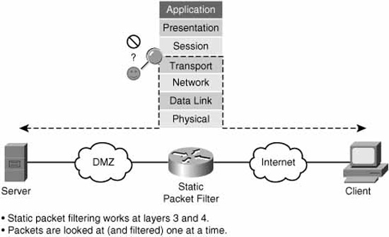
Static packet-filtering routers are relatively unintelligent. By using ACLs, they can either permit or deny traffic up to the layer 4 of the OSI model, but they don’t see the PDUs (Protocol Data Units) that carry the data as part of a dynamic conversation. For example, they can permit traffic if it matches the well-known TCP port number for HTTP, port 80, but they can only filter the packets singly and have no appreciation for how a TCP connection is built, carries and re-transmits data as required, and is torn down.
A static packet-filtering firewall is like unknowledgeable fans at a tennis match. They can watch single volleys go across the net, but they don’t see the ball in the context of game, set, and match. If you think of the tennis ball as a TCP segment, for example, the analogy is complete. These fans may be qualified to let volleys with the green-colored (destination port 80) balls across the net, but the finer points of how the game is started (begin TCP session), played (data flow), and ended (session torn down) is beyond them. You could even give the fans further responsibilities, telling them that the green ball (TCP port 80) is only allowed from player A (source IP address) to player B (destination IP address), but they will still only be able to examine each volley separately.
Static packet-filtering firewalls are very useful for simple, not particularly granular, rules . . . “big chunk” rules like, “Absolutely no TCP Port 80 traffic is allowed inbound past the perimeter.”
Be careful how you use ACLs, however. In Figure 5.3, a static packet filtering firewall is configured to permit Internet users to access the web server in the DMZ.

Refer to “A” in Figure 5.3. The ACL is applied inbound on the Internet facing interface, FastEthernet 0/0/1 in the figure.
access-list 101 permit tcp any host 192.168.1.20 eq 80
interface FastEthernet 0/0/1
ip access-group 101 in
Recall from your CCNA studies that when you create an ACL, you also create an implicit rule at the very end of the ACL, whether you enter it or not:
access-list 101 deny ip any any
All traffic that doesn’t match the access control list entries (ACE) before this last statement will therefore be implicitly denied. This also means that you have to have at least one permit somewhere in the ACL; otherwise, all traffic is doomed for failure!
The effect is that only destination port 80 traffic will be allowed in through the firewall and only to IP address 192.168.1.20, the public IP address of the web server in the DMZ. Replies from the web server will be allowed out, because there is no interface ACL applied outbound on the Internet-facing interface. “Great!” you say. Mission accomplished. But what about the inside PC? Can it make connections out to the Internet server (point “B” in Figure 5.3)? Yes, but replies will be blocked on the implied rule in access-list 101. This happens because the firewall is only looking at packets one at a time. It doesn’t see the return packets from the Internet server as part of a conversation that was started from the inside PC and allowed outbound. Stupid firewall! How could you solve this problem with the existing network topology? You could do one of the following:
![]() Add ACEs to access-list 101, allowing the source port number of every conceivable Internet application that your users are allowed to access inbound through the firewall.
Add ACEs to access-list 101, allowing the source port number of every conceivable Internet application that your users are allowed to access inbound through the firewall.
![]() Apply access-list 101 outbound on the DMZ interface instead of inbound on the Internet interface.
Apply access-list 101 outbound on the DMZ interface instead of inbound on the Internet interface.
![]() Upgrade to a dynamic packet filtering firewall.
Upgrade to a dynamic packet filtering firewall.
The first choice is impractical, not to mention it creates a large vulnerability. The second choice is feasible, but the effort would have to be replicated for every internal interface on your network, and might create a management nightmare. The third choice might be the best one and might even be accomplished with a Cisco IOS software upgrade and some small re-configuration and without the need for additional hardware.
So, where would you deploy a static packet-filtering firewall? A good example would be a Cisco IOS router configured with ACLs as a static packet-filtering firewall at the network edge. This customer-managed Internet router, connected to an ISP router, could enforce perimeter security as part of a layered defense strategy. It wouldn’t be very good at communications security, core network security, or endpoint security (of the four firewall roles covered previously), but that isn’t its intended role.
Advantages of static packet-filtering firewalls include the following:
![]() Simple permit/deny rules
Simple permit/deny rules
![]() Little or no impact on network performance
Little or no impact on network performance
![]() Simple to configure
Simple to configure
![]() Supported on most routers
Supported on most routers
![]() Good first level of defense at a lower OSI layer (“big chunk” rules)
Good first level of defense at a lower OSI layer (“big chunk” rules)
![]() 90% of effectiveness of high-end firewalls at an appreciably lower cost
90% of effectiveness of high-end firewalls at an appreciably lower cost
Disadvantages of static packet-filtering firewalls include the following:
![]() Difficult to catch IP spoofing
Difficult to catch IP spoofing
![]() Filtering fragmented IP packets is problematic
Filtering fragmented IP packets is problematic
![]() Implementation and maintenance of complex ACLs
Implementation and maintenance of complex ACLs
![]() Some applications/services cannot be filtered
Some applications/services cannot be filtered
![]() Stateless (only one packet at a time)
Stateless (only one packet at a time)
Figure 5.4 illustrates the basic operation of an application layer gateway.
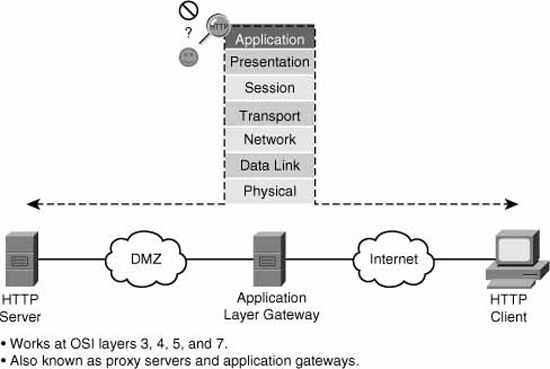
An application layer gateway (or proxy server) is a firewall that proxies a client’s connection to a server at layers 5 and 7 (session and application) of the OSI model.
Note
When describing layered network architecture, it is often convenient to group layers 5, 6, and 7 of the OSI model into a single application layer. Thus, the TCP/IP protocol stack can line up, layer-by-layer, with the OSI model for layers 1 to 4, with a single layer 5. It is at this single, composite application layer that application layer gateways operate.
Referring to Figure 5.4, here are the steps that illustrate the operation of an application layer gateway:
![]() At the application layer, the client first connects to the application layer gateway.
At the application layer, the client first connects to the application layer gateway.
![]() (Optional) The user is authenticated to the proxy at the application layer.
(Optional) The user is authenticated to the proxy at the application layer.
![]() The application layer gateway proxies (acts on behalf of) the client’s connection to the application server.
The application layer gateway proxies (acts on behalf of) the client’s connection to the application server.
![]() The application layer gateway accepts replies from the application server.
The application layer gateway accepts replies from the application server.
![]() The application layer gateway forwards the replies to the client.
The application layer gateway forwards the replies to the client.
If the proxy server is not operational, the client will not be able to connect. No proxy = no service.
Advantages of application layer gateways include the following:
![]() Persons, and not devices, are authenticated.
Persons, and not devices, are authenticated.
![]() DoS attacks are made more difficult because it is harder for hackers to spoof as theirs isn’t a direct path to the target system.
DoS attacks are made more difficult because it is harder for hackers to spoof as theirs isn’t a direct path to the target system.
![]() Option to monitor and filter application data.
Option to monitor and filter application data.
![]() Option to configure detailed logging.
Option to configure detailed logging.
Limitations of application layer gateways include the following:
![]() Software processing of packets can be CPU-intensive.
Software processing of packets can be CPU-intensive.
![]() Can be memory and disk-intensive, too. (We have to store the cached connection information somewhere!)
Can be memory and disk-intensive, too. (We have to store the cached connection information somewhere!)
![]() Requires a proxy per application.
Requires a proxy per application.
![]() Limited number of application supported.
Limited number of application supported.
![]() Sometimes requires additional client configuration or software.
Sometimes requires additional client configuration or software.
As a general recommendation, only use application layer gateways in key situations where increased security is an acceptable tradeoff for less performance.
Note
Recall that there are six bits in a TCP segment header that, depending on which combination of bits is set, describe the state of a TCP session. TCP defines rules for the combinations of bit settings that are allowed. A stateful packet-filtering firewall will also understand these rules. The bits are as follows:
![]() URG = Urgent
URG = Urgent
![]() ACK = Acknowledge
ACK = Acknowledge
![]() PSH = Push
PSH = Push
![]() RST = Reset
RST = Reset
![]() SYN = Synchronize
SYN = Synchronize
![]() FIN = Finish (or finalize)
FIN = Finish (or finalize)
Figure 5.5 illustrates the basic operation of a dynamic (or stateful) packet-filtering firewall.

A dynamic packet-filtering firewall is like a knowledgeable tennis fan or umpire. They understand all the rules of the game and can permit or deny volleys that don’t follow the rules. They can filter all the way up to layer 4 of the OSI model like the static packet-filtering firewall can, but they also understand that:
![]() A game starts with an opening serve from the player who has service (requester send SYN).
A game starts with an opening serve from the player who has service (requester send SYN).
![]() The in-bounds serve is supposed to be returned by the opponent (responder sends SYN, ACK), but sometimes it is rejected (responder sends RST) because the opponent is not ready.
The in-bounds serve is supposed to be returned by the opponent (responder sends SYN, ACK), but sometimes it is rejected (responder sends RST) because the opponent is not ready.
![]() If the initial player receives the ball back from the opponent (SYN, ACK), they will return the ball (thank you very much!) with an (ACK) and the volley continues. The initial three-way handshake (SYN; SYN, ACK; ACK) is complete.
If the initial player receives the ball back from the opponent (SYN, ACK), they will return the ball (thank you very much!) with an (ACK) and the volley continues. The initial three-way handshake (SYN; SYN, ACK; ACK) is complete.
![]() Either the initial server or the opponent can tear down the volley (the TCP session) at any time by sending a (FIN) to their opponent, beginning a four-way handshake that culminates in the session’s (the volley’s) termination.
Either the initial server or the opponent can tear down the volley (the TCP session) at any time by sending a (FIN) to their opponent, beginning a four-way handshake that culminates in the session’s (the volley’s) termination.
In this manner, the firewall builds a database of connections that are built across it and the state that they are in. This is called the state table. Here’s what a stateful firewall does with every packet that is lobbed across it:
![]() The packet is checked first to see if there is a pre-existing connection between the end systems’ (client and server) sockets.
The packet is checked first to see if there is a pre-existing connection between the end systems’ (client and server) sockets.
Note
A socket is made up of an IP address + a port number. The two sockets (source and destination) uniquely identify the circuit between the connection partners.
![]() If the state table indicates that there is an existing connection between the sockets, the state table is further referenced for that connection and the flags (SYN, ACK, RST, and so on) in the packet are checked to see if they are valid for that connection. For example, once a connection is set up, the firewall would refuse any further SYNs between the sockets, as they are used only when the connection is first being set up.
If the state table indicates that there is an existing connection between the sockets, the state table is further referenced for that connection and the flags (SYN, ACK, RST, and so on) in the packet are checked to see if they are valid for that connection. For example, once a connection is set up, the firewall would refuse any further SYNs between the sockets, as they are used only when the connection is first being set up.
![]() If a connection doesn’t already exist, the firewall will allow it to be built as long as no ACL denies the initial SYN. The connection state is put into the state table (see the following note).
If a connection doesn’t already exist, the firewall will allow it to be built as long as no ACL denies the initial SYN. The connection state is put into the state table (see the following note).
Note
It is important to note that stateful firewalls only consult an interface ACL once: when the connection is being set up with the initial SYN. All subsequent packets are checked against the state table. As long as the packet matches the correct state per the state table, as well as other information like sequence numbers, the packet is allowed through the firewall.
Therefore, unlike static packet-filtering firewalls, an interface ACL on a stateful firewall only needs to permit that first SYN. There is no need to have another ACL to allow the correct response (for example, SYN, ACK, or RST), as would likely be the case with a static packet-filtering firewall.
In this fashion, the stateful firewall is plug-and-play. You only need to permit a connection to be initiated in one direction, and the firewall will dynamically create a rule to allow the return flow. This makes configuration that much simpler. Referring again to Figure 5.3, the network would function as designed if the static packet-filtering IOS router/firewall was replaced with a dynamic packet-filtering firewall.
Dynamic packet-filtering firewalls can enforce perimeter security. They also can ensure core network security insofar as they can detect anomalies in traffic patterns. Often they employ VPN technologies and can therefore manage some of C-I-A implicit in communications network security.
Uses of dynamic packet-filtering firewalls include the following:
![]() Intelligent first level of defense
Intelligent first level of defense
![]() Primary defense mechanism
Primary defense mechanism
![]() Augmenting static packet filtering
Augmenting static packet filtering
![]() Improving routing throughput
Improving routing throughput
![]() Proof against spoofing and DoS attacks
Proof against spoofing and DoS attacks
Limitations of dynamic packet-filtering firewalls include the following:
![]() Doesn’t filter at the application layer.
Doesn’t filter at the application layer.
![]() Not all protocols are stateful like TCP (for example: ICMP, UDP, some routing protocols).
Not all protocols are stateful like TCP (for example: ICMP, UDP, some routing protocols).
![]() Some applications use multiple channels and dynamic port numbers negotiated above the transport layer (for example: FTP, RealAudio, some multimedia).
Some applications use multiple channels and dynamic port numbers negotiated above the transport layer (for example: FTP, RealAudio, some multimedia).
![]() Cannot authenticate users to connections (because this occurs at a higher layer of the OSI model).
Cannot authenticate users to connections (because this occurs at a higher layer of the OSI model).
As a general recommendation, deploy stateful firewalls as the premier defense mechanism of a secure network architecture.
Figure 5.6 illustrates a firewall that works at the application layer.

At first glance, you might assume that application layer gateways and application inspection firewalls are synonymous. They are not. Though they both work at the application layer (really, layers 5, 6, and 7) of the OSI model, an application inspection firewall will perform deep packet inspection at the application layer in order to determine that protocols that are proceeding across the firewall are compliant with the organization’s security policy. At the same time, the application inspection firewall can ensure that the protocol is standards-compliant and also look for signs of unauthorized protocols tunneled inside the application session. For example, the eDonkey protocol that is used by the popular P2P application, Kazaa, could be blocked when it appears inside an HTTP session.
Here’s another example. Refer to Figure 5.6. The network security policy says that anonymous FTP is allowed to the FTP server in the DMZ, but that no one is allowed to alter, move, create, copy, or delete files or directories. This would be typical of a public mirror site supporting a Linux distribution, perhaps on a university’s network. We could instruct the computer science student who is managing the FTP server, that the server’s patch revision must be up-to-date and that it is configured correctly to allow only anonymous FTP with access control per the security policy. The application inspection firewall could be configured to inspect the FTP command channel (recalling that FTP uses two channels: one for command/control and another for data) and block unauthorized activity at the application layer.
For this to occur, the firewall needs to have an intrinsic understanding of how the application layer protocol works. This higher intelligence is not found on all firewall products and can distinguish one vendor’s products from another. It is often bundled with dynamic packet filtering as part of a Unified Threat Management (UTM) product.
The final category of firewalls is transparent firewalls. A transparent firewall, as its name implies, starts making forwarding and filtering decisions at the data link layer (layer 2) of the OSI model. It works in a secure bridging mode at layer 2, while offering rich layers 2 through 7 security services.
Figure 5.7 illustrates the basic layer 2 functionality of a transparent firewall.
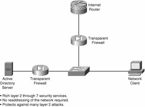
The four other firewall categories mentioned previously are all fundamentally IP firewalls. A transparent firewall, on the other hand, can filter and forward other protocol suites (such as AppleTalk, Novell IPX, DEC VMS, and so on) based on identifying information in the Ethernet frame header. It can also guard against some common layer 2 attacks such as ARP table poisoning, DHCP spoofing, and MAC flooding by virtue of its layer 2-aware design.
Like a switch, the transparent firewall is invisible at layer 3, requiring no readdressing of the network.
The Cisco family of firewalls includes the following:
![]() Cisco IOS firewalls
Cisco IOS firewalls
![]() Cisco PIX 500 Series firewalls
Cisco PIX 500 Series firewalls
![]() Cisco ASA 5500 Series Adaptive Security appliances
Cisco ASA 5500 Series Adaptive Security appliances
The following are features of Cisco IOS firewalls:
![]() Zone-based policy framework
Zone-based policy framework
![]() Application layer firewalling for email, web, and other traffic
Application layer firewalling for email, web, and other traffic
![]() IM and P2P application filtering
IM and P2P application filtering
![]() VoIP inspection and firewalling
VoIP inspection and firewalling
![]() Virtual Routing and Forwarding (VRF) support
Virtual Routing and Forwarding (VRF) support
![]() Wireless integration (if equipped)
Wireless integration (if equipped)
![]() Stateful failover
Stateful failover
![]() Local URL filtering: whitelist and blacklist support
Local URL filtering: whitelist and blacklist support
![]() National Institute of Science and Technology (NIST) Federal Information Processing Standard (FIPS) 140 and Common Criteria certifications
National Institute of Science and Technology (NIST) Federal Information Processing Standard (FIPS) 140 and Common Criteria certifications
![]() Dynamic Multipoint VPN (DMVPN)
Dynamic Multipoint VPN (DMVPN)
The following are features of Cisco PIX 500 Series firewalls:
![]() Advanced application-aware firewall services
Advanced application-aware firewall services
![]() VoIP and multimedia security
VoIP and multimedia security
![]() Site-to-site and remote access IPsec VPN
Site-to-site and remote access IPsec VPN
![]() Five models:
Five models:
![]() PIX 501 (SOHO / ROBO)
PIX 501 (SOHO / ROBO)
![]() PIX 506E (ROBO / SMB)
PIX 506E (ROBO / SMB)
![]() PIX 515E (SMB / Enterprise)
PIX 515E (SMB / Enterprise)
![]() PIX 525 (Enterprise)
PIX 525 (Enterprise)
![]() PIX 535 (Enterprise / SP)
PIX 535 (Enterprise / SP)
The following are features of Cisco ASA 5500 Series Adaptive Security appliances:
![]() Intelligent threat defense
Intelligent threat defense
![]() Secure Sockets Layer (SSL) and IPsec VPN
Secure Sockets Layer (SSL) and IPsec VPN
![]() IPS
IPS
![]() Content Security Services
Content Security Services
![]() Cisco Unified Communications (voice and video)
Cisco Unified Communications (voice and video)
![]() Key component of the Cisco Self-Defending Network
Key component of the Cisco Self-Defending Network
![]() Five models:
Five models:
![]() ASA 5505 (SOHO / ROBO)
ASA 5505 (SOHO / ROBO)
![]() ASA 5510 (ROBO / SMB)
ASA 5510 (ROBO / SMB)
![]() ASA 5520 (SMB / Enterprise)
ASA 5520 (SMB / Enterprise)
![]() ASA 5540 (Enterprise)
ASA 5540 (Enterprise)
![]() ASA 5550 (Enterprise / SP)
ASA 5550 (Enterprise / SP)
According to Cisco, this is a summary of the most important best practices for integrating firewalls into a comprehensive security policy:
![]() Place firewalls at key network security boundaries.
Place firewalls at key network security boundaries.
![]() Although firewalls are the primary security device, it is unrealistic to assume that the firewall is all that is needed for security.
Although firewalls are the primary security device, it is unrealistic to assume that the firewall is all that is needed for security.
![]() Adopt a “deny all” strategy by default. Deny all traffic except that which is expressly needed. (See Chapter 2, “Building a Secure Network Using Security Controls.”)
Adopt a “deny all” strategy by default. Deny all traffic except that which is expressly needed. (See Chapter 2, “Building a Secure Network Using Security Controls.”)
![]() Do not forget physical controls on firewall access.
Do not forget physical controls on firewall access.
![]() Regularly monitor firewall logs for signs of intrusion. (See Chapter 4, “Implementing Secure Management and Hardening the Router.”)
Regularly monitor firewall logs for signs of intrusion. (See Chapter 4, “Implementing Secure Management and Hardening the Router.”)
![]() Make sure that changes to the firewall’s configuration occur within an overall change management policy.
Make sure that changes to the firewall’s configuration occur within an overall change management policy.
![]() Firewalls are primarily technical controls against outside attack. Do not let internal security lapse as a result.
Firewalls are primarily technical controls against outside attack. Do not let internal security lapse as a result.
![]() Adopt strong administrative controls and physical controls to complement the firewall’s technical controls.
Adopt strong administrative controls and physical controls to complement the firewall’s technical controls.
You should already have an understanding of the basics of ACLs as covered in CCNA material. This being the case, we can forgo the basics of creating and applying access lists to interfaces (and also vtys) in favor of focusing on examples and recommendations for their use. We will look at some specific examples of their use, both using the CLI and the Cisco SDM.
In this section, we examine the use of interface ACLs in the context of creating a static packet-filtering firewall and examining the relative strengths and weaknesses of this type of firewall. Remember, these are not particularly intelligent firewalls but, as we see, they do have an important role in the Cisco Self-Defending Network.
Exam Alert
ACLs will be on the exam. Understand them thoroughly in the context of static packet filtering per the prerequisite courses ICND1 and ICND2.
ACLs can mitigate the following types of threats:
![]() Inbound IP address spoofing
Inbound IP address spoofing
![]() Outbound IP address spoofing
Outbound IP address spoofing
![]() DoS and DDoS TCP SYN attacks
DoS and DDoS TCP SYN attacks
![]() DoS smurf attacks
DoS smurf attacks
![]() Inbound and outbound ICMP messages (used for DoS attacks and reconnaissance)
Inbound and outbound ICMP messages (used for DoS attacks and reconnaissance)
![]() Traceroute (used for reconnaissance)
Traceroute (used for reconnaissance)
There are two different meanings for “inbound” and “outbound,” depending on the context in which they are used:
![]() Definition One—Security Zone Context.The words “inbound” and “outbound” are used in the preceding list. What do they mean? Do they indicate directions of packet flow relative to security zones? In this context, yes. Outbound traffic is traffic flowing from a more-trusted zone to a less-trusted zone. Inbound traffic is traffic flowing from a less-trusted zone to a more-trusted zone.
Definition One—Security Zone Context.The words “inbound” and “outbound” are used in the preceding list. What do they mean? Do they indicate directions of packet flow relative to security zones? In this context, yes. Outbound traffic is traffic flowing from a more-trusted zone to a less-trusted zone. Inbound traffic is traffic flowing from a less-trusted zone to a more-trusted zone.
![]() Inbound.For example, IP packets arriving inbound on an Internet-facing interface should never have a source address of an internal network. Configuring an ACL to check the source addresses would be relatively simple.
Inbound.For example, IP packets arriving inbound on an Internet-facing interface should never have a source address of an internal network. Configuring an ACL to check the source addresses would be relatively simple.
![]() Outbound.Similarly, packets arriving on a LAN interface (or leaving an Internet-facing interface) would constitute outbound traffic, and should only contain source addresses from the organization’s own address space, whether they are network address translated or not.
Outbound.Similarly, packets arriving on a LAN interface (or leaving an Internet-facing interface) would constitute outbound traffic, and should only contain source addresses from the organization’s own address space, whether they are network address translated or not.
![]() Definition Two—Interface ACL Context.“Inbound” and “outbound” can also be relative to the interfaces themselves. This is an important distinction because after you create an interface ACL, you have to apply it either in(bound) or out(bound) on an interface.
Definition Two—Interface ACL Context.“Inbound” and “outbound” can also be relative to the interfaces themselves. This is an important distinction because after you create an interface ACL, you have to apply it either in(bound) or out(bound) on an interface.
![]() Inbound ACLs.These ACLs check packets as they arrive on an interface from a connected network. For example, a packet that arrives on a LAN interface from the physical network that it is connected to would be inbound. Thus, this traffic has not been routed yet and, in fact, the router hasn’t decided whether to route it or not. Inbound ACLs are more efficient in terms of processing because if a packet is denied by the ACL, no CPU time has been wasted performing a routing table lookup. A permitted packet will be routed.
Inbound ACLs.These ACLs check packets as they arrive on an interface from a connected network. For example, a packet that arrives on a LAN interface from the physical network that it is connected to would be inbound. Thus, this traffic has not been routed yet and, in fact, the router hasn’t decided whether to route it or not. Inbound ACLs are more efficient in terms of processing because if a packet is denied by the ACL, no CPU time has been wasted performing a routing table lookup. A permitted packet will be routed.
![]() Outbound ACLs.These ACLs check the packets after they have been dispatched to the correct interface per the routing table and prior to being forwarded to the connected network. A permitted packet will be sent to the output buffer and a denied packet will be discarded.
Outbound ACLs.These ACLs check the packets after they have been dispatched to the correct interface per the routing table and prior to being forwarded to the connected network. A permitted packet will be sent to the output buffer and a denied packet will be discarded.
Exam Alert
Make sure you understand what context these terms are being used in when taking the exam. Misunderstanding the context is a sure recipe for confusion.
Note
Encrypted packets are tested on the ACL twice. If a packet is encrypted, it will first be tested on the inbound ACL to determine whether encrypted packets are allowed. If it is allowed, the packet is decrypted before it is again tested on the inbound ACL.
Let’s review how to identify ACLs on Cisco IOS routers:
![]() Numbered ACL:
Numbered ACL:
![]() The number indicates the protocol that is being filtered.
The number indicates the protocol that is being filtered.
![]() The ranges 1–99 and 1300–1999 indicate standard ACLs (filter all of IP, source address only). Cannot create a layer 4 firewall with these.
The ranges 1–99 and 1300–1999 indicate standard ACLs (filter all of IP, source address only). Cannot create a layer 4 firewall with these.
![]() The ranges 100–199 and 2000–2699 indicate extended ACLs (filter IP, protocols encapsulated in IP, source and destination socket [address and port] as applicable). Can create a layer 4 firewall with these.
The ranges 100–199 and 2000–2699 indicate extended ACLs (filter IP, protocols encapsulated in IP, source and destination socket [address and port] as applicable). Can create a layer 4 firewall with these.
![]() Named ACL:
Named ACL:
![]() Can use custom name for ACL (available from Cisco IOS Release 11.2).
Can use custom name for ACL (available from Cisco IOS Release 11.2).
![]() Rules: Names contain alphanumeric characters but no spaces or punctuation. Must begin with an alphabetic character.
Rules: Names contain alphanumeric characters but no spaces or punctuation. Must begin with an alphabetic character.
![]() Can be either standard or extended.
Can be either standard or extended.
![]() Can add or delete entries within the ACL.
Can add or delete entries within the ACL.
We look at two examples of ACLs in action using the CLI. This will be a useful review of basic ACL concepts, as first we create and apply a numbered extended ACL and second, examine the use of established parameters in ACLs, as well as how to edit an existing ACL.
Figure 5.8 illustrates the goals of the ACL we are creating.
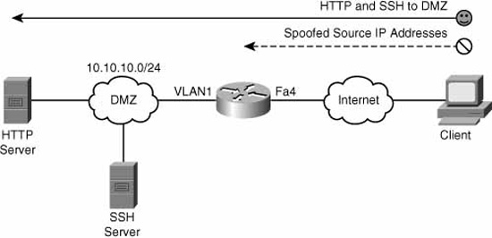
The following CLI commands match Figure 5.8. First, we create the ACL and then apply it to the Internet-facing interface, FastEthernet 4. This is a very common and practical use for an ACL. ACLs are usually applied on perimeter devices, such as routers, where simple rules can be used. The idea is to get rid of traffic that is absolutely not allowed as early as possible, leaving whatever is left over for other devices further inside our network. This concept of nesting of perimeters is discussed in Chapter 4. In this example, we create an anti-spoofing rule, ensuring that the source address of any inbound packets to our network do not match our internal network. Then we explicitly permit the traffic that is allowed, namely traffic to the HTTP and SSH servers in the Demilitarized Zone (DMZ).
CiscoISR(config)#access-list 101 remark —- anti-spoofing rule
CiscoISR(config)#access-list 101 deny ip 10.10.10.0 0.0.0.255 any
CiscoISR(config)#access-list 101 remark — — permit HTTP and SSH to inside
CiscoISR(config)#access-list 101 permit tcp any 10.10.10.0 0.0.0.255 eq 80
CiscoISR(config)#access-list 101 permit tcp any 10.10.10.0 0.0.0.255 eq 22
CiscoISR(config)#interface FastEthernet 4
CiscoISR(config-if)#ip access-group 101 in
You can review the access-list and the matches against the ACEs with the show access-list command. Note that the remarks do not display with the show access-list command output. You can only see them when you view the running-config:
CiscoISR#show access-list 101
Extended IP access list 101
10 deny ip 10.10.10.0 0.0.0.255 any (109 matches)
20 permit tcp any 10.10.10.0 0.0.0.255 eq www (11532 matches)
30 permit tcp any 10.10.10.0 0.0.0.255 eq 22 (23453 matches)
CiscoISR(config)#
Note
Strictly speaking, the anti-spoofing rule is not necessary because the non-HTTP and SSH traffic is denied by the implicit deny-all statement at the end of the access-list. Best practices dictate that explicit rules will allow for the logging of specific attacks (note there are 109 matches in the preceding ACL), and by putting the anti-spoofing ACE early in the ACL, the attack is thwarted early on and there’s no possibility that it might accidentally be permitted by a later ACE.
Note that the show access-list 101 command displays sequence numbers (10, 20, 30, and so on) in the numbered ACL. As of Cisco IOS Software Release 12.3, you can delete and insert ACEs using these sequence numbers. For example, if we wanted to delete sequence 10 (the anti-spoofing ACE), we could enter these CLI commands:
CiscoISR(config)#ip access-list extended 101
CiscoISR(config-ext-nacl)#no 10
CiscoISR(config-ext-nacl)#
This deletes ACE 10, but does not re-sequence the ACL:
CiscoISR#show access-list 101
Extended IP access list 101
20 permit tcp any 10.10.10.0 0.0.0.255 eq www (11989 matches)
30 permit tcp any 10.10.10.0 0.0.0.255 eq 22 (23492 matches)
CiscoISR(config)#
You can use similar logic to insert ACEs too. Let’s combine that thought with the established parameter in the next example.
The second example covers the two concepts of established command and inserting ACEs. A static packet filtering router will never be stateful. That said, what if you want to make sure that applying an ACL to an interface does not drop existing TCP sessions? The established parameter in an ACE allows the router to examine the flags in the TCP header and permit TCP segments that have the RST or ACK bit set because only active TCP sessions would have at least one or the other of these bits set. Continuing with the previous example (also refer to Figure 5.8), if you wanted to ensure that all existing TCP sessions remain active, you could enter this CLI command to put it at the beginning of access-list 101:
CiscoISR(config)#ip access-list extended 101
CiscoISR(config-ext-nacl)#5 permit tcp any any established
CiscoISR(config-ext-nacl)#do show access-list 101
Extended IP access list 101
5 permit tcp any any established (96 matches)
20 permit tcp any 10.10.10.0 0.0.0.255 eq www (12032 matches)
30 permit tcp any 10.10.10.0 0.0.0.255 eq 22 (25000 matches)
CiscoISR(config-ext-nacl)#
Of course, we don’t know what existing TCP sessions are being permitted across our firewall, so best practices dictate that we would specify minimally the port number of the established protocol that is being permitted. For example, if the HTTP server in the DMZ were somehow hijacked by a hacker, it might try to initiate a connection out to the Internet using some other protocol, perhaps Telnet (TCP Port 23). If we left ACL 101 as is, the hijacked server could initiate a Telnet connection (SYN) outbound to the Internet and the reply (SYN, ACK) would be allowed back through the firewall on the established ACE in the ACL. Not good!
You can verify that an ACL is applied on an interface and what direction it is applied in by using the show ip interface command:
CiscoISR#show ip interface FastEthernet 4
FastEthernet4 is up, line protocol is up
Internet address is 192.168.99.218/25
Broadcast address is 255.255.255.255
Address determined by non-volatile memory
MTU is 1500 bytes
Helper address is not set
Directed broadcast forwarding is disabled
Outgoing access list is not set
Inbound access list is 101
Proxy ARP is disabled
[output omitted]
Table 5.1 outlines Cisco’s general best practices for the use of ACLs.

Using the Cisco SDM to configure ACLs follows the same rules as using the CLI. First, you create the ACL, and then you apply it to the interface in the correct direction.
Exam Alert
By this chapter, you will have noticed that much of the manual configuration of the device is performed in the Cisco SDM starting at Configure->Additional Tasks.
In this example, we create an extended ACL (if you master this, you can easily do a standard ACL) called “inside-servers” that will permit HTTP and SSH to the DMZ. In fact, this ACL will follow the example we just completed in the CLI.
-
Choose Configure->Additional Tasks->ACL Editor->Access Rules.
-
Click Add. The Add a Rule window appears.
-
Enter a name or number for the ACL in the Add a Rule window (following the rules for names and number ranges, of course!). We’ll give it the name inside-servers.
-
Confirm that Extended Rule is selected in the drop-down list. You can also put in a rule description (optional).
-
Click Add. The Add an Extended Rule Entry window appears.
Figure 5.9 illustrates the addition of an extended ACL entry using the Cisco SDM.
-
Choose Permit or Deny from the Select an action drop-down list. You can also add a description (fewer than 100 characters) in the Description field. We will choose Permit.
-
You have a choice of either using Any IP Address (that is, the default) for the address, or you can construct the IP addresses by selecting the address type in the Type drop-down list. The Type drop-down list gives you three choices:
 A Network A Host Name or IP Address Any IP Address (selected by default)
In the Destination Host/Network list, we choose A Network in this example. Enter the IP address of the network and a wildcard mask as required (10.10.1.0 and 0.0.0.255, respectively, in our example).

8. For the Source Host/Network, we choose Any IP Address because we don’t know what the source address will be of the Internet users of our DMZ servers.
9. We’re not done yet! Click the radio button in the Protocol and Services section that corresponds to the protocol that is being filtered—TCP, in our case.
10. Again, we can’t be too specific about the source port because we don’t know what dynamic port number the Internet client will choose, so we’ll leave it at the default, which is = and any.
11. We can be specific for the destination port because it is a WWW server, so we choose = and www, respectively, for the destination port. You can also manually enter the destination port number or name.
12. If our security policy dictates that we need to log access to the DMZ server, we can check the Log matches against this entry check box.
13. Click OK when finished. This will return you to the Add a Rule window.
14. Repeat the preceding steps, but for the SSH server too (which is at Destination Port = 22). You can either click Add and go through all the steps again, or you can click the Clone button that will clone the selected entry and then you can simply edit the Destination Port number in the resultant Add an Extended Rule Entry window.
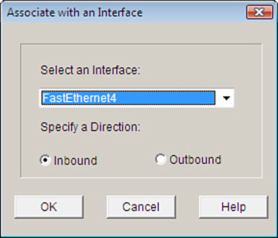
15. The ACL doesn’t do anything by itself. It now must be associated with an interface. Click the Associate button and select the interface and direction in the Associate with an Interface window.
Figure 5.10 illustrates the dialog box for associating an ACL to an interface in the Cisco SDM.
FIGURE 5.10 Associating an ACL to an interface in the Cisco SDM.
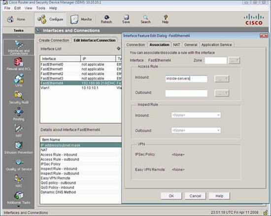
16. Alternatively you can choose Configure->Interfaces and Connections and select the interface you want to associate the ACL with. In the Interface Feature Edit Dialog window, put in the ACL name or number in the Inbound or Outbound access rule fields, as shown in Figure 5.11.
You may recall from Chapter 4 that there were a number of services that run on the router by default, which would be useful to lock down. Some of these services could be used by an attacker for reconnaissance. Some others might make the router vulnerable to DoS attacks. In this example, we are configuring the router so it will only accept RIP, EIGRP, and OSPF routing table updates from IP address 192.168.99.129, a neighbor router. This will mitigate the possibility that a knowledgeable attacker could engineer routing packets that inject erroneous routing table information into the router. Neither OSPF nor EIGRP use TCP or UDP for transport. They are services that use their own protocol IDs and are encapsulated directly into the IP packet header. The protocol ID field in the IP packet header identifies what protocol is inside the IP packet. An OSPF router, for example, would ignore IP packets with protocol ID 88 because that protocol ID identifies EIGRP. Some useful numbers to remember are as follows:
![]() ICMP:protocol ID 1
ICMP:protocol ID 1
![]() TCP:protocol ID 6
TCP:protocol ID 6
![]() UDP:protocol ID 17
UDP:protocol ID 17
![]() GRE:protocol ID 47 (used by Microsoft VPNs and others)
GRE:protocol ID 47 (used by Microsoft VPNs and others)
![]() ESP:protocol ID 50 (used by IPsec VPNs)
ESP:protocol ID 50 (used by IPsec VPNs)
![]() EIGRP:protocol ID 88 (proprietary Cisco routing protocol)
EIGRP:protocol ID 88 (proprietary Cisco routing protocol)
![]() OSPF:protocol ID 89 (open standard routing protocol)
OSPF:protocol ID 89 (open standard routing protocol)
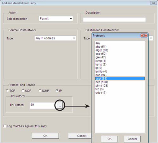
While constructing an ACL in the Cisco SDM, you can click on the ellipse beside the IP Protocol field to see a list of the built-in protocol IDs in the Cisco SDM. You can also manually enter the protocol ID number if it is not in the list. Figure 5.12 shows the Protocol window in the Add an Extended Rule Entry window.
Here are the resulting CLI commands in the configuration generated by the Cisco SDM for the named extended IP ACL inbound-routing:
ip access-list extended inbound-routing
remark SDM_ACL Category=1
permit ospf host 192.168.99.129 any
permit eigrp host 192.168.99.129 any
permit udp host 192.168.99.129 any eq rip
interface FastEthernet 4
ip access-group inbound-routing in
As indicated in Figure 5.8 and in the accompanying subsection, “ACL Examples Using the CLI,” ACLs can be very effective in mitigating IP address spoofing attacks. We will examine their use in mitigating both inbound IP address spoofing and outbound IP address spoofing.
In general, the source IP address in packets arriving inbound (that is, from a less-trusted network) should not be the same as an internal network’s IP address range. That said, there are other source IP addresses that have no business being in these inbound packets. Here are guidelines for other IP addresses that normally should not be in the source address field, particularly when this Internet is connected to the Internet and therefore public, routable IP address space:
![]() Local addresses.127.0.0.0/8 (used for loopback testing, for example).
Local addresses.127.0.0.0/8 (used for loopback testing, for example).
![]() Reserved private addresses.Defined in RFC 1918, Address Allocation for Private Internets.
Reserved private addresses.Defined in RFC 1918, Address Allocation for Private Internets.
![]() IP multicast addresses.224.0.0.0/4.
IP multicast addresses.224.0.0.0/4.
![]() Any address starting with a 0.0.0.0.0/24 (for example, DHCP uses 0.0.0.0 in the source address field for DHCP requests).
Any address starting with a 0.0.0.0.0/24 (for example, DHCP uses 0.0.0.0 in the source address field for DHCP requests).
![]() All 1’s source IP addresses.255.255.255.255.
All 1’s source IP addresses.255.255.255.255.
Remember ACL 101 that we created earlier to permit traffic to the DMZ and only to the HTTP and SSH servers there? Let’s take the opportunity to put a few key points together and modify it. We will follow the guideline of most specific ACEs first that we covered in a previous section, which means that we have a problem already. If we start adding ACEs to the existing numbered ACL 101, the new ACEs will go to the bottom of the ACL.
Note
Another tricky thing here is the wildcard masks used in the ACEs. Remember that the wildcard mask is an inverse mask, with 0’s being the matching bits and 1’s being the don’t care bits. If you don’t understand this, and the following example doesn’t make any sense, then you have some review to do. For example, a /24 subnet mask would be represented as 255.255.255.0 with a regular mask, but as 0.0.0.255 as a wildcard mask.
First, use the show access-list 101 command to verify the existing ACL:
CiscoISR(config)#do show access-list 101
Extended IP access list 101
10 permit tcp any 10.10.10.0 0.0.0.255 eq www
20 permit tcp any 10.10.10.0 0.0.0.255 eq 22
CiscoISR(config)#
Then, use the new features of Cisco IOS Software version 12.3 and later that enable you to use sequence numbers to add statements to an existing numbered ACL. We must insert these new lines ahead of the existing sequence number 10:
CiscoISR(config)#ip access-list extended 101
CiscoISR(config-ext-nacl)#1 deny ip 0.0.0.0 0.255.255.255 any
CiscoISR(config-ext-nacl)#2 deny ip 10.0.0.0 0.255.255.255 any
CiscoISR(config-ext-nacl)#3 deny ip 127.0.0.0 0.255.255.255 any
CiscoISR(config-ext-nacl)#4 deny ip 172.16.0.0 0.15.255.255 any
CiscoISR(config-ext-nacl)#5 deny ip 192.168.0.0 0.0.255.255 any
CiscoISR(config-ext-nacl)#6 deny ip 224.0.0.0 15.255.255.255 any
CiscoISR(config-ext-nacl)#7 deny ip host 255.255.255.255 any
Why stop there? Still following the guideline of most specific tests first, why don’t we insert ACEs that will allow EIGRP and OSPF from 192.168.99.129/32, per the example in the section “Using ACLs to Filter Network Services,” in this chapter (we would put RIP in there too, but we’ve run out of room if we want to insert it ahead of ACE 10!):
CiscoISR(config-ext-nacl)#8 permit eigrp host 192.168.99.129 any
CiscoISR(config-ext-nacl)#9 permit ospf host 192.168.99.129 any
Verify ACL 101:
CiscoISR(config-ext-nacl)#do show access-list 101
Extended IP access list 101
1 deny ip 0.0.0.0 0.255.255.255 any (50 matches)
2 deny ip 10.0.0.0 0.255.255.255 any
3 deny ip 127.0.0.0 0.255.255.255 any
4 deny ip 172.16.0.0 0.15.255.255 any
5 deny ip 192.168.0.0 0.0.255.255 any
6 deny ip 224.0.0.0 15.255.255.255 any (99937 matches)
7 deny ip host 255.255.255.255 any
8 permit eigrp host 192.168.99.129 any (2232 matches)
9 permit ospf host 192.168.99.129 any (156 matches)
10 permit tcp any 10.10.10.0 0.0.0.255 eq www (11345 matches)
20 permit tcp any 10.10.10.0 0.0.0.255 eq 22
CiscoISR(config-ext-nacl)#
Generally speaking, the source address in IP packets that are leaving your network should belong to your address space, whether the addresses are RFC 1918 addresses or publicly routable. In this example, we create an ACL named no-spoof-out and apply it to the Vlan1 interface (default LAN interface on a Cisco 800 series ISR) in the inbound direction. Figure 5.13 illustrates the effects of the cumulative example we have been working on.

Figure 5.13 illustrates the net, cumulative effect of all the previous ACL examples.
CiscoISR(config)#ip access-list extended no-spoof-out
CiscoISR(config-ext-nacl)#permit ip 10.10.10.0 0.0.0.255 any
CiscoISR(config-ext-nacl)#exit
CiscoISR(config)#interface Vlan 1
CiscoISR(config-if)#ip access-group no-spoof-out in
CiscoISR(config-if)#
If ACLs were only as straightforward in practice as our examples are so far! Chances are good that there are other services that will need to be allowed through the static packet-filtering firewall. For example, if your security policy allows it, you may need to be able to ping (that is, ICMP echo request) devices on the inside of your network in the DMZ from the outside for network management reasons. Speaking of network management, you may have some devices that need to be managed by SNMP. In the example that we have been working on, neither ICMP nor SNMP are allowed through the firewall because they are being denied by the implicit rules. Not only do you have to allow these protocols inbound, but their replies need to be allowed outbound. You have to ensure that existing ACLs will allow these responses.
Note
In our example, we needn’t be worried about blocking the replies because the ACL no-spoof-out allows anything whose source address comes from the DMZ through the firewall.
We could create an ACE in ACL 101 that would allow all ICMP inbound, but do we really want to do this? Our security policy dictates which protocols are required for business reasons. Because in the last chapter we agreed that ICMP (and other services) can be used for reconnaissance and DoS attacks, it makes good sense to only allow specific messages through the firewall. In this example, we would want to allow ICMP echoes through the firewall to the DMZ and allow the replies back out. Certainly this will allow an attacker to determine live IP hosts in the DMZ, and also engineer an ICMP flood. If we don’t allow other ICMP commands through (such as ICMP redirects, which can be used for certain exploits), then this may be a reasonable tradeoff.
Exam Alert
Cisco specifically recommends against allowing ICMP echoes and ICMP redirects (as mentioned) inbound. We are allowing ICMP echoes through because it fits with the worked example, but when asked on an exam, always answer the Cisco way!
The following CLI command adds a rule that will allow ICMP echoes from any IP address to 10.0.0.0/8. Note the use of the inverse mask, 0.0.0.255, being the inverse of 255.0.0.0:
CiscoISR(config)#access-list 101 permit icmp any 10.10.10.0 0.0.0.255 echo
Because we didn’t insert this command with a sequence number, it will be added to the end of the existing ACL 101 before the implicit deny.
Here’s a list of some useful ICMP messages you may want to filter:
![]() Echo.Allows pinging to IP hosts.
Echo.Allows pinging to IP hosts.
![]() Echo-reply.Replies to pinging.
Echo-reply.Replies to pinging.
![]() Unreachable.Reply indicating that a host cannot be reached.
Unreachable.Reply indicating that a host cannot be reached.
![]() Redirect.Command to alter a routing table.
Redirect.Command to alter a routing table.
![]() parameter-problem.Invalid/problem packet header.
parameter-problem.Invalid/problem packet header.
![]() Packet-too-big.Required for Maximum Transmission Unit (MTU) path discovery.
Packet-too-big.Required for Maximum Transmission Unit (MTU) path discovery.
![]() Source-quench.Throttles traffic as necessary.
Source-quench.Throttles traffic as necessary.
The CLI and the Cisco SDM have built-in keywords for the following common and router service traffic:
![]() Common Services.domain, smtp, ftp.
Common Services.domain, smtp, ftp.
![]() Router Service Traffic.telnet, syslog, snmptrap.
Router Service Traffic.telnet, syslog, snmptrap.
The last section examines the configuration of a static packet-filtering firewall using interface ACLs. In this section, we leverage on Cisco’s Zone-Based Policy Firewall (ZPF) to create a dynamic packet-filtering firewall. ZPF is not Cisco’s first foray into dynamic packet filtering technology. Before ZPF, Cisco offered Context-Based Access Control (CBAC, pronounced “see-back”), later changing its name to IOS Classic Firewall. As we know, “classic” infers that it is older, so if you want the latest and greatest dynamic packet-filtering firewall technology, you will want to master the Cisco Zone-Based Policy Firewall.
Note
We will implement a stateful packet inspection and application layer firewall by leveraging on the Cisco IOS Zone-Based Policy Firewall. If you already understand the fundamentals of both, go ahead and read this section. If you don’t, and you have skipped the earlier section, “Examining and Defining Firewall Technologies,” now is the time to go back and carefully read it through. You have been warned!
As we have seen, when you only have a few interfaces on the firewall, configuring ACLs on a static packet-filtering firewall isn’t an enormous task. However, even with a pair of interfaces, by the time you have sorted all the permutations and combinations of pairing reply traffic with requests, rule order logic, and inbound versus outbound, the need for a disciplined configuration management approach as well as much testing is crucial.
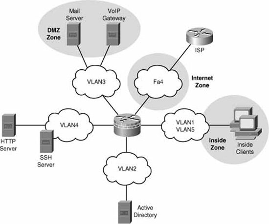
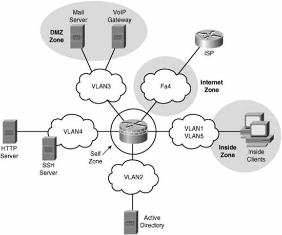
Now imagine that you had five interfaces on the firewall (see Figure 5.14). The number of permutations with just the choice of applying ACLs inbound vs. outbound on 5 interfaces = 25 = 32 possible interactions to troubleshoot.

This is one of the reasons for the Cisco Zone-Based Policy Firewall (ZPF). ZPF enables you to group interfaces into security zones and design rules using the Cisco Common Classification Policy Language (C3PL) for traffic moving between the different zones.
For example, using ZPF for access rules by grouping DMZ1 and DMZ2 into a DMZ zone, Inside1 and Inside2 into a INSIDE zone, and the Internet uplink into its own INTERNET zone, you could create and troubleshoot rule interaction between three different security zones equally as easily as you would use ACLs on a three-interface firewall. C3PL is the language that is used to classify (or differentiate) traffic that flows between the different zones and take different security, and QoS actions on the flows. Of course, this is a security course, so you know that the focus will be on security policies for the traffic!
It’s not too early to look at a general overview of the workflow in configuring for ZPF. The following list is a high-level overview of the concepts, while trying to avoid Cisco terminology as much as possible:
-
Create zones.For example, DMZ, INSIDE, and INTERNET.
-
Assign interfaces to a zone.Vlan1 and Vlan2 in INSIDE zone; Vlan 3 and Vlan 4 in DMZ zone; FastEthernet 4 in INTERNET zone.
-
Define pairs of zones called “zone pairs.”.inbound-to-dmz, inbound-to-inside; outbound-to-internet.
-
Classify traffic.Classify traffic into flows.
-
Inter-zone pair inspection policy.Create an inspection policy for the classified traffic traveling between the zones in the zone pair.
Note
By grouping interfaces into zones, it makes it simple to add or remove interfaces because once an interface is associated to a zone, the security policy is immediately enforced without worrying about the extra abstraction and complexity of creating and applying ACLs and inspection (ip inspect) rules. That was the way that it used to be done with the legacy Cisco IOS Stateful Inspection called Context-Based Access Control (CBAC) firewall.
There are six main advantages of the ZPF, as follows:
![]() Grouping.Physical and virtual interfaces are grouped into zones.
Grouping.Physical and virtual interfaces are grouped into zones.
![]() Zone Traversal.Firewall policies are applied to traffic traversing zones.
Zone Traversal.Firewall policies are applied to traffic traversing zones.
![]() Simplicity.Adding and removing interfaces into zones automatically integrates them into the firewall policy.
Simplicity.Adding and removing interfaces into zones automatically integrates them into the firewall policy.
![]() ACL Independence.ZPF is not dependent on ACLs (see the following note).
ACL Independence.ZPF is not dependent on ACLs (see the following note).
![]() Troubleshooting.C3PL makes policies easier to visualize.
Troubleshooting.C3PL makes policies easier to visualize.
![]() Security Posture.ZPF turns the IOS router into a “deny unless explicitly permitted” firewall (reverse of the logic of the legacy stateful inspection model).
Security Posture.ZPF turns the IOS router into a “deny unless explicitly permitted” firewall (reverse of the logic of the legacy stateful inspection model).
The other advantage is conceptual. Because ZPF is so visual, especially when using the Cisco SDM, it aids in learning how stateful firewalls operate and applying the rules in an intuitive fashion.
The six main supported features of ZPF are as follows:
![]() Stateful (Dynamic) packet inspection
Stateful (Dynamic) packet inspection
![]() Application layer firewall
Application layer firewall
![]() URL filtering
URL filtering
![]() Transparent firewall
Transparent firewall
![]() Per-policy parameter
Per-policy parameter
![]() Virtual Routing and Forwarding (VRF)-aware firewall
Virtual Routing and Forwarding (VRF)-aware firewall
There are three main categories of actions that the ZPF can take on traffic:
![]() Inspect.Stateful inspection. Monitor outbound traffic and statefully inspect the return traffic to ensure that it matches session table entries.
Inspect.Stateful inspection. Monitor outbound traffic and statefully inspect the return traffic to ensure that it matches session table entries.
![]() Drop.Analogous to a deny ACE in an ACL.
Drop.Analogous to a deny ACE in an ACL.
![]() Pass.Analogous to a permit ACE in an ACL (not stateful as is the inspect action).
Pass.Analogous to a permit ACE in an ACL (not stateful as is the inspect action).
Refer to Figure 5.15. Note that the network zone topology has changed from Figure 5.14. Interfaces Vlan2 and Vlan4 are no longer members of zones. Vlan5 has been added to the INSIDE zone. This is just the kind of situation that will drive you crazy! Perhaps the INSIDE, DMZ, and INTERNET zones were configured previously and you have just added two interfaces without yet putting them in zones. If you let your intuition guide you (and remembering that the firewall will err on the side of caution), you could probably figure this out for yourself, but let’s look at the possible combinations of results.
What will happen to traffic that would be routed between two interfaces when ZPF is fully or partially configured? Here are the possible results with examples:
![]() Vlan2 to Vlan4.Inter-interface traffic is permitted (normally routed) if neither interface is a member of a zone.
Vlan2 to Vlan4.Inter-interface traffic is permitted (normally routed) if neither interface is a member of a zone.
![]() Vlan1 to Vlan3.If the interfaces are in two different zones, and there is a ZPF policy configured for that zone-pair, the policy actions (inspect, drop, or pass) will dictate what to do with the traffic.
Vlan1 to Vlan3.If the interfaces are in two different zones, and there is a ZPF policy configured for that zone-pair, the policy actions (inspect, drop, or pass) will dictate what to do with the traffic.
If the interfaces are in two different zones, and there is no ZPF policy configured, the traffic will be dropped. (The firewall errs on the side of caution!)
![]() Vlan2 to FastEthernet4.If one interface is in a zone and the other one isn’t, the traffic is dropped.
Vlan2 to FastEthernet4.If one interface is in a zone and the other one isn’t, the traffic is dropped.
![]() Vlan1 to Vlan5.If the interfaces are in the same zone (zone-pair is therefore not applicable) the traffic is passed.
Vlan1 to Vlan5.If the interfaces are in the same zone (zone-pair is therefore not applicable) the traffic is passed.
What about traffic that either originates from or is destined to the router itself? By default, this traffic is permitted. The exception is where the traffic flows in a zone-pair in which the router’s zone is a member (see note about the “self” zone below). In this latter case, the traffic either from or to the router will be subject to the actions (inspect, drop, or pass) specified in the ZPF policy. Figure 5.16 illustrates the self zone.
Note
The router is automatically put in a special zone called the “self” zone when ZPF is configured. Figure 5.16 illustrates this.
A basic firewall is essentially a firewall that has two zones: inside (trusted) and outside (untrusted). The Cisco SDM Basic Firewall wizard enables you to do the following:
![]() Create a stateful firewall policy between these zones, inspecting outbound TCP, UDP, and router-generated ICMP traffic.
Create a stateful firewall policy between these zones, inspecting outbound TCP, UDP, and router-generated ICMP traffic.
![]() Block all IM (MSN, AOL, and Yahoo!) whether its tunneled in HTTP or not.
Block all IM (MSN, AOL, and Yahoo!) whether its tunneled in HTTP or not.
![]() Deny traffic from outside to inside zones.
Deny traffic from outside to inside zones.
Follow these steps to configure ZPF using the Cisco SDM Basic Firewall Wizard. Starting from the Cisco SDM home page:
-
Select Configure->Firewall and ACL.
-
Ensure that the Basic Firewall radio button is selected and then push the Launch the selected task button.
-
The Basic Firewall Configuration Wizard window appears. Click Next.
-
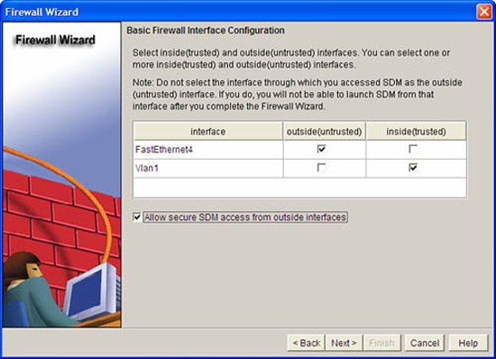
Select the interface(s) that will be in the outside zone and the inside zone. At least one interface must be in each zone in order to continue. Check the Allow secure SDM access from outside interfaces check box if you will be accessing the SDM from an interface in the untrusted zone.
Figure 5.17 illustrates the Basic Firewall Interface Configuration window in the Firewall Wizard.
-
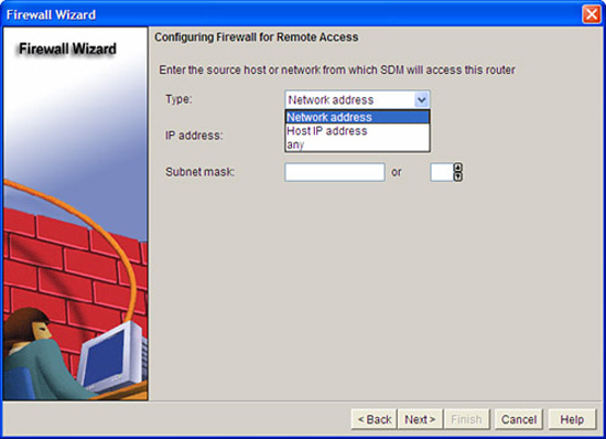
If you have selected the Allow secure SDM access from outside interfaces check box in the previous step, you will be prompted to set a policy for which range of IP addresses will be allowed to access the SDM from the outside zone. (Sound like a zone-pair that includes the self zone?) In the Type drop-down box, choose either Network address, Host IP address, or any. This dialog is illustrated in Figure 5.18.
-
Click Next. An Information window appears, indicating that the SDM connection will be dropped when the configuration is delivered to the firewall. Click OK on this window.
-
The Basic Firewall Security Configuration window appears. A slider control gives you a choice of applying either a high, medium, or low security policy. The default is high security. Click Next to accept the default.
-
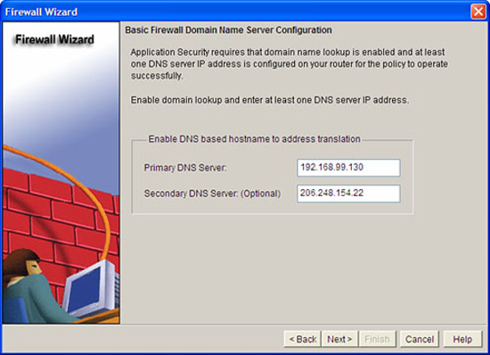
The Basic Firewall Domain Name Server Configuration window appears, as illustrated in Figure 5.19. DNS is needed for application security, mainly because the domain names for IM services have to be resolved and the High Security policy (per the last step) will block IM. Fill in at least the Primary DNS Server and click Next.
-
The Firewall Configuration Summary window appears. This window presents a summary of the ZPF rules that will be applied to the router. The following is an example of the information in the Firewall Configuration Summary window. Refer to Figures 5.14 and 5.15 because the interfaces and zones in this summary match up with that example. This is not a preview of the CLI commands per se; it is just a summary of the policies that will be applied when the wizard is finished:
Note: Do not select the interface through which you accessed SDM as the
outside (untrusted) interface. If you do, you will not be able to launch
SDM from that interface after you complete the Firewall Wizard.
Inside(trusted) Interfaces:
Vlan1 (10.10.10.1)
Outside(untrusted) Interface:
FastEthernet4 (192.168.99.218)
Service Policy Configuration:
In-zone -> Out-zone:
Inspect TCP,UDP,H323,SIP,SCCP and other protocols
Deny packets with invalid ip address as source
Application Inspection for HTTP:
Block HTTP port-misuse for IP,P2P
Block HTTP protocol violation
Block HTTP request methods other than post,head,get
Block http request response containing non-ascii characters
Application Inspection for Instant Messaging:
Block all services of msn,yahoo,aol with log action
Application Inspection for P2P:
Block file transfer over edonkey,fasttrack,gnutella and kazaa2
Block text-chat over edonkey
Application Inspection for Email:
Block invalid command for imap,pop3
Block SMTP session with data length over 5 MB
Self -> Out-zone:
Inspect router generated ICMP traffic
Out-zone -> Self:
Permit secure SDM Access to router (HTTP,SSH,RCP) from specified
source.
Deny all other traffic.
DNS Configuration:
Primary DNS:192.168.99.130
Secondary DNS:206.248.154.22 -
Click Finish. The SDM delivers the configuration to the router. This is illustrated in Figure 5.20.
Recall Step 4. If you were accessing the SDM from the outside (untrusted) zone, you will lose the connection. Reconnect to the router using a secure http connection.
-
Navigate to the home page of the Cisco SDM and verify that the ZPF has been applied by looking for a green check mark beside the Firewall Policies menu. Expand the menu with the down arrow on the right-hand side. This is illustrated in Figure 5.21.
-
Navigate to Configure->Firewall and ACL->Edit Firewall Policy to see a visual representation of the rule flow, as indicated in the bottom of the window illustrated in Figure 5.22.


The following CLI commands match the preceding example of using the SDM Basic Firewall Wizard.
!— — — — — — — — — —
!1. CREATE CLASS MAPS
!— — — — — — — — — —
class-map type inspect smtp match-any sdm-app-smtp
match data-length gt 5000000
class-map type inspect match-any SDM_HTTPS
match access-group name SDM_HTTPS
class-map type inspect match-any SDM_SSH
match access-group name SDM_SSH
class-map type inspect match-any SDM_SHELL
match access-group name SDM_SHELL
class-map type inspect match-any sdm-cls-access
match class-map SDM_HTTPS
match class-map SDM_SSH
match class-map SDM_SHELL
class-map type inspect http match-any sdm-app-nonascii
match req-resp header regex sdm-regex-nonascii
class-map type inspect imap match-any sdm-app-imap
match invalid-command
class-map type inspect match-any sdm-cls-protocol-p2p
match protocol edonkey signature
match protocol gnutella signature
match protocol kazaa2 signature
match protocol fasttrack signature
match protocol bittorrent signature
class-map type inspect match-any SDM_OSPF
match access-group name SDM_OSPF
class-map type inspect match-any sdm-cls-insp-traffic
match protocol dns
match protocol https
match protocol icmp
match protocol imap
match protocol pop3
match protocol tcp
match protocol udp
class-map type inspect match-all sdm-insp-traffic
match class-map sdm-cls-insp-traffic
class-map type inspect match-any SDM-Voice-permit
match protocol h323
match protocol skinny
match protocol sip
class-map type inspect match-any SDM_OSPF_TRAFFIC
match class-map SDM_OSPF
class-map type inspect match-all sdm-protocol-pop3
match protocol pop3
class-map type inspect match-any sdm-cls-icmp-access
match protocol icmp
match protocol tcp
match protocol udp
class-map type inspect match-any sdm-cls-protocol-im
match protocol ymsgr yahoo-servers
match protocol msnmsgr msn-servers
match protocol aol aol-servers
class-map type inspect pop3 match-any sdm-app-pop3
match invalid-command
class-map type inspect match-all sdm-access
match class-map sdm-cls-access
match access-group 101
class-map type inspect match-all SDM_OSPF_PT
match class-map SDM_OSPF_TRAFFIC
class-map type inspect match-all sdm-protocol-p2p
match class-map sdm-cls-protocol-p2p
class-map type inspect http match-any sdm-http-blockparam
match request port-misuse im
match request port-misuse p2p
match request port-misuse tunneling
match req-resp protocol-violation
class-map type inspect match-all sdm-protocol-im
match class-map sdm-cls-protocol-im
class-map type inspect match-all sdm-icmp-access
match class-map sdm-cls-icmp-access
class-map type inspect match-all sdm-invalid-src
match access-group 100
class-map type inspect http match-any sdm-app-httpmethods
match request method bcopy
match request method bdelete
match request method bmove
match request method bpropfind
match request method bproppatch
match request method connect
match request method copy
match request method delete
match request method edit
match request method getattribute
match request method getattributenames
match request method getproperties
match request method index
match request method lock
match request method mkcol
match request method mkdir
match request method move
match request method notify
match request method options
match request method poll
match request method post
match request method propfind
match request method proppatch
match request method put
match request method revadd
match request method revlabel
match request method revlog
match request method revnum
match request method save
match request method search
match request method setattribute
match request method startrev
match request method stoprev
match request method subscribe
match request method trace
match request method unedit
match request method unlock
match request method unsubscribe
class-map type inspect match-all sdm-protocol-http
match protocol http
class-map type inspect match-all sdm-protocol-smtp
match protocol smtp
class-map type inspect match-all sdm-protocol-imap
match protocol imap
!
!— — — — — — — — — — —
!2. CREATE POLICY MAPS
!— — — — — — — — — — —
policy-map type inspect sdm-permit-icmpreply
class type inspect sdm-icmp-access
inspect
class class-default
pass
policy-map type inspect http sdm-action-app-http
class type inspect http sdm-http-blockparam
log
reset
class type inspect http sdm-app-httpmethods
log
reset
class type inspect http sdm-app-nonascii
log
reset
class class-default
policy-map type inspect smtp sdm-action-smtp
class type inspect smtp sdm-app-smtp
reset
class class-default
policy-map type inspect imap sdm-action-imap
class type inspect imap sdm-app-imap
log
reset
class class-default
policy-map type inspect pop3 sdm-action-pop3
class type inspect pop3 sdm-app-pop3
log
reset
class class-default
policy-map type inspect sdm-inspect
class type inspect sdm-invalid-src
drop log
class type inspect sdm-protocol-http
inspect
service-policy http sdm-action-app-http
class type inspect sdm-protocol-smtp
inspect
service-policy smtp sdm-action-smtp
class type inspect sdm-protocol-imap
inspect
service-policy imap sdm-action-imap
class type inspect sdm-protocol-pop3
inspect
service-policy pop3 sdm-action-pop3
class type inspect sdm-protocol-p2p
drop log
class type inspect sdm-protocol-im
drop log
class type inspect sdm-insp-traffic
inspect
class type inspect SDM-Voice-permit
inspect
class class-default
pass
policy-map type inspect sdm-permit
class type inspect sdm-access
inspect
class type inspect SDM_OSPF_PT
pass
class class-default
!
!— — — — — — — — — — — —
!3. CREATE SECURITY ZONES
!— — — — — — — — — — — —
zone security out-zone
zone security in-zone
!— — — — — — — — — — — —
!4. CREATE ZONE PAIRS
!— — — — — — — — — — — —-
zone-pair security sdm-zp-self-out source self destination out-zone
service-policy type inspect sdm-permit-icmpreply
zone-pair security sdm-zp-out-self source out-zone destination self
service-policy type inspect sdm-permit
zone-pair security sdm-zp-in-out source in-zone destination out-zone
service-policy type inspect sdm-inspect
!
!— — — — — — — — — — — — — — — — —
!5. ASSOCIATE INTERFACES WITH ZONES
!— — — — — — — — — — — — — — — — —
interface FastEthernet4
zone-member security out-zone
!
interface Vlan1
zone-member security in-zone
To configure ZPF manually, here are the four basic steps:
-
Create zones.
-
Create class maps.
-
Create policy maps (and actions: inspect, drop, or pass).
-
Create zone pairs and assign policy maps to zone pairs.
These steps are summarized in Figure 5.23 and are covered in more detail in the following sections through an example of manually configuring ZPF with the Cisco SDM. Refer to Figure 5.14 for the network diagram that this example follows.

Follow these steps to create a zone:
-
Select Configure->Additional Tasks->Zones.
-
Click Add to create a new zone in the Zone panel, which is illustrated in Figure 5.24.
-
Enter a zone name in the Zone Name field of the Add a Zone window.
-
Select the interfaces that will be associated with that zone name by placing a check mark in the check box beside the interface name. Physical interfaces can be placed in only one zone, whereas virtual interfaces (such as dialer interfaces or bridged virtual interfaces) can be in multiple zones.
-
Click OK on the next two dialogs to create the zone and deliver the commands to the router.

Note
Be mindful of zone behavior per the earlier “Zone Behavior” section, because the policies have not been configured nor applied to the zone pairs yet!
The next step to creating a ZPF policy is to define a Layer 3-4 class map. The class map will identify traffic that will have actions applied to it by policy maps (next step). For example, you might want all TCP traffic to be statefully inspected from the INSIDE zone to the INTERNET zone, with additional deep packet inspection (see the following note) applied to HTTP to ensure that it is both protocol-compliant and that IM traffic isn’t tunneled inside it. In Figure 5.25, a class map is created that will eventually be used to 1) identify, then 2) inspect outbound traffic (that is, from the INSIDE zone to the INTERNET zone) for IM protocols MSN, Yahoo, and AOL as well as for miscellaneous P2P (Peer to Peer) traffic such as BitTorrent and Kazaa. Remember, the class map doesn’t do anything but identify the traffic.
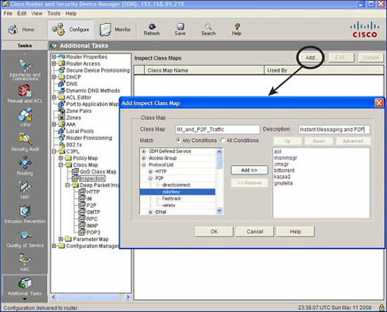
In order to identify the traffic, one or more distinguishing characteristics must be determined and based on the following criteria:
![]() Access-group.An ACL (standard or extended) can be applied to a class map.
Access-group.An ACL (standard or extended) can be applied to a class map.
![]() Protocol.TCP, UDP, ICMP, and application layer protocols such as HTTP, SMTP, IM, and P2P can be used as distinguishing characteristics. Any protocol (either user-defined or well-known) understood by Port-to-Application Mapping (PAM) can be specified.
Protocol.TCP, UDP, ICMP, and application layer protocols such as HTTP, SMTP, IM, and P2P can be used as distinguishing characteristics. Any protocol (either user-defined or well-known) understood by Port-to-Application Mapping (PAM) can be specified.
![]() Class-map.Class maps can be nested inside another class map to provide additional match criteria.
Class-map.Class maps can be nested inside another class map to provide additional match criteria.
Once the class maps are created, create policy maps and associate class maps to them along with actions (inspect, drop, or pass). See Figure 5.26 for the steps in the Cisco SDM.

When you are done, Figure 5.27 shows what your policy map should look like when class maps and actions are associated to it. In this example, the policy map has two class maps associated to it with Drop/Log and Inspect actions, respectively.
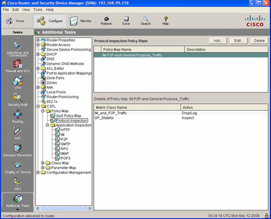
Create a zone pair to which the policy map will be assigned. Assign the policy map to the zone pair in the same dialog, as illustrated in Figure 5.28.
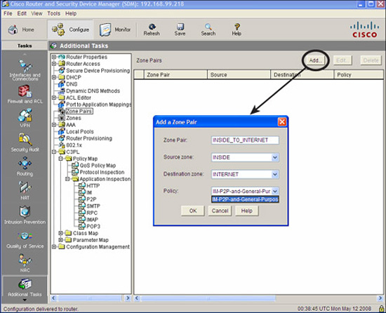
Zone-Based Policy Firewall can be monitored using either the CLI or the Cisco SDM. To monitor ZPF with the Cisco SDM, choose Monitor->Firewall Status. Select the firewall policy from the list of policies and choose either: Active Sessions, Dropped Packets, or Allowed Packets, from the list on the left-hand side, as illustrated in Figure 5.29.
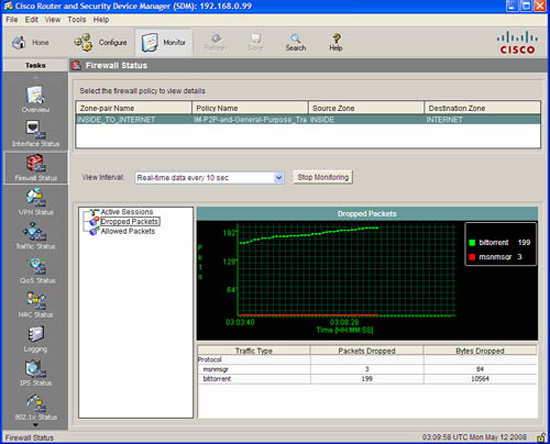
The equivalent CLI command is show policy-map type inspect zone-pair session. The output of this command is shown a little later. See if you can identify these items:
![]() The zone pair name.
The zone pair name.
![]() The service policy that was applied to the zone pair.
The service policy that was applied to the zone pair.
![]() The class maps that are associated to the service policy.
The class maps that are associated to the service policy.
![]() The actions that the policy map takes for each class map.
The actions that the policy map takes for each class map.
Note
Hint: The command’s output is indented to show objects nested within others. Shading has been added to the output of the show policy-map type inspect zone-pair session command later to make it easier for you to identify the items in the previous list.
Not so fast! Before issuing the show policy-map type inspect zone-pair session command, first verify that the zones are set up per Figure 5.14:
CiscoISR#show zone security INSIDE
zone INSIDE
Member Interfaces:
Vlan1
Vlan2
CiscoISR#show zone security INTERNET
zone INTERNET
Member Interfaces:
FastEthernet4
CiscoISR#show zone security DMZ
zone DMZ
Member Interfaces:
Vlan3
Vlan4
Now, look at the CLI output of the show policy-map type inspect zone-pair session command for detail of the traffic that was inspected, dropped, or passed by the policy map IM-P2P-and-General-Purpose_Traffic that was applied to the zone pair INSIDE_TO_INTERNET.
![]() Traffic that matches on class-map IM_and_P2P_Traffic will be dropped. Thus, IM (MSN Messenger) and P2P traffic (BitTorrent) will be dropped.
Traffic that matches on class-map IM_and_P2P_Traffic will be dropped. Thus, IM (MSN Messenger) and P2P traffic (BitTorrent) will be dropped.
![]() Traffic that matches on class-map GP_Stateful will be inspected. Thus, TCP and UDP traffic will be statefully inspected.
Traffic that matches on class-map GP_Stateful will be inspected. Thus, TCP and UDP traffic will be statefully inspected.
![]() Traffic that matches on class-map class-default will be dropped. Thus, all other traffic will be dropped.
Traffic that matches on class-map class-default will be dropped. Thus, all other traffic will be dropped.
Note that some of the output was omitted to ensure comprehension:
CiscoISR#show policy-map type inspect zone-pair session
Zone-pair: INSIDE_TO_INTERNET
Service-policy inspect : IM-P2P-and-General-Purpose_Traffic
Class-map: IM_and_P2P_Traffic (match-any)
Match: protocol msnmsgr
3 packets, 84 bytes
30 second rate 0 bps
Match: protocol bittorrent
1 packets, 28 bytes
30 second rate 0 bps
Drop
4 packets, 112 bytes
Class-map: GP_Stateful (match-any)
Match: protocol tcp
127 packets, 3916 bytes
30 second rate 0 bps
Match: protocol udp
390 packets, 29217 bytes
30 second rate 2000 bps
Inspect
Established Sessions
Session 8394B708 (192.168.0.101:5762)=>(72.247.244.32:80) tcp
SIS_OPEN
Created 00:01:39, Last heard 00:00:49
Bytes sent (initiator:responder) [4661:3726]
Session 83944270 (192.168.0.101:5757)=>(72.247.244.32:80) tcp
SIS_OPEN
Created 00:01:39, Last heard 00:00:37
Bytes sent (initiator:responder) [5734:3299]
Session 839472C8
(192.168.0.101:50454)=>(68.40.182.79:19313) udp SIS_OPENING
Created 00:00:09, Last heard 00:00:09
Bytes sent (initiator:responder) [67:0]
Class-map: class-default (match-any)
Match: any
Drop (default action)
0 packets, 0 bytes