CHAPTER 4
Intelligent Cap Interface for Wheelchair Control1
Many disabled people do not have the dexterity necessary to use a joystick or other hand interface for controlling a standard robotic wheelchair. In many cases, some of them suffer from diseases that can damage most of the nervous and muscular systems in the body but leave the brain and eye movement unimpaired. To this end, we developed an interface that enables a person to guide a robotic wheelchair by eye-gaze, using a minimal number of electrodes attached on the head of the user (Figure 4.1). The device can measure the electrooculographic potential (EOG) of the eye-gaze movement together with the electromyographic signals (EMG) from the jaw muscle motion. By coupling these simple actions, one can navigate a wheelchair solely by the eyes and the jaw, which provides an aid to mobility for people with a disability.
4.1 INTRODUCTION
Autonomous robotic wheelchairs represent an important class of autonomous mobile robots that is receiving increasing attention all over the world. This attention is due to the growing need for easier wheelchair mobility throughout a longer average life of people with a disability. Generally, the design of these powered wheelchairs follows the general principles, technologies, and methodologies of the other autonomous mobile robots. However, they must possess particular characteristics such as maneuverability, navigation, and safety that call for specialized designs.
Robotics wheelchairs require the integration of many areas of research, including vision, indoor/outdoor navigation, navigation with maps, reactive navigation, mode selection, sensor fusion, and user interfaces. However, most of these studies focus on the capability of autonomous navigation or, generally speaking, assistive navigation, by using vision or other sensing devices such as ultrasonic and infrared.

Figure 4.1. Interface on a cap.
The aim of intelligent wheelchairs is to provide wheelchairs with an ability to be controlled and navigated with minimal interactions with the users, in order to enhance the quality of service for people with a handicap. The most typical guidance device for a robotic wheelchair is a joystick. Other alternatives such as voice control, breath expulsion control, and guidance by head movements are also used.
Standard robotic wheelchairs have been in use for a long time; however, many people with a disability do not have the ability to control an ordinary powered wheelchair. An extreme disability such as severe cerebral palsy or amyotrophic lateral sclerosis (ALS) deprives them of the use of their limbs and certain muscles movement. Therefore, it is extremely difficult to express themselves through speech or bodily movement to command a robotic wheelchair. Some other advanced control alternatives for the robotic wheelchair users are worth exploring, which can meet the requirements for people with different levels of disability.
One of the solutions for the problem is to navigate by eye-gaze. In fact, there are several existing approaches to sense the eye movements. Most of these approaches involve the use of a camera to track some features of the eyes to determine where the user is looking, whereas another approach is to sense the EOG. In Refs. [1] and [2], a method to control and guide mobile robots by means of the ocular position (eye displacement into its orbit) is introduced. This method requires five electrodes to be placed around the eyes in order to detect the up and down, left and right movement of the eyes (Figure 4.2).
In our work, we have developed a device that measures the horizontal eye-gaze motions (looking to the left/right) and the jaw motion. By coupling these motions, the user can navigate a robotic wheelchair solely by the eyes and the jaw by using a minimal number of electrodes, which provides an aid to mobility for people with a disability.
This chapter is organized as follows: Section 4.2 discusses the bioelectrical signals in the human body. Section 4.3 describes the approach we are using in this work. Section 4.4 introduces the design of the interface. Section 4.5 is the experimental implementations, and Section 4.6 is the conclusion.

Figure 4.2. Traditional sensor placement method.
4.2 ELECTROMYOGRAPHY AND ELECTROOCULOGRAPHY
Electromyography (EMG) is a method of studying the activity of a muscle by recording action potentials from the contracting fibers. This method has been of value in the analysis of the actions of different muscles in the maintenance of posture and in the study of the physiology of motor unit activity. The signals that measured from the movement of the eyeball (ocular muscle) is typically known as EOG.
These bioelectric signals can be detected with surface electrodes that are easy to apply and can be worn for long periods of time while posing no health or safety risk to the user. Another advantage of this input method is that the hardware involved is comparatively simple, so that it is possible to design an EMG/EOG-based interface with minimal hardware in real-world applications.
4.3 APPROACH
The methods in Refs. [1–3] require five electrodes to issue the forward, backward, left, and right commands (Figure 4.2). In our approach, we demonstrated that three electrodes should be sufficient enough to guide a robotics wheelchair (Figure 4.3): one for the ground signal, and the remaining two for measuring 1) the eye-gaze at the horizontal direction and 2) the activation of the jaw muscles to trigger the forward/backward command. Table 4.1 compares the assignment of wheelchair commands in different approaches.
Figure 4.4 shows part of the muscles in a human's head. Region A is the location of ocular muscle, and EOG signals of the eyeball movement can be detected in this area. Region B is called the temporal muscle, and this piece of fan-shaped muscle elevates the jaw and clenches the teeth. When the jaw moves, EMG signals will be detected at Region B. If we place a electrode at the overlapping area of Regions A and B, both signals produced by the eye movement and the jaw motion could be detected. The location is roughly the location of the temple between the eye and the ear on each side of the head (there maybe a slight variation from person to person).

Figure 4.3. New sensor placement method.
Study in Ref. [4] showed that several problems would occur when this kind of eye movement interface is used. First of all, the eyes move jerky and rarely sit still, which results in inaccuracy in the performance of the device. Other factors like eyelid movement, variations in an individual's skin conductivity, and electrode placement also affect the results. To deal with the first problem, instead of using the interface as a direct substitute for a joystick, we treat the eye movements as “switches” to trigger different commands. For the latter problem, we reduced the number of electrodes to be used.
Table 4.1. Comparison of Using Different Approaches
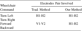

Figure 4.4. Muscles on the head.
We designed the input pattern when using this interface to command a robotic wheelchair (Table 4.2). Since people with a disability cannot turn back to look clearly at the scene behind the wheelchair, we suggested that it would be dangerous to allow the backward motion to be controlled by him/her. Therefore, we have disabled the backward command in our design. In fact, if the wheelchair system has been equipped with certain obstacles avoidance abilities, the user does not necessarily need to execute this command. As a summary, this approach has the following advantages:
- Stability and reliability increase
- Simple instrumentation
- Lower cost
- More comfortable to use
4.4 INTERFACE
4.4.1 Hardware
The electronic circuit is designed to detect the horizontal eye-gaze and the jaw motion. Three silver-silver chloride electrodes are applied on the surface of the skin to pick up the bioelectrical signal produced from the muscles. Since the signals are weak, we use an instrumentation amplifier as the pre-amplifier. This signal is a combination of a muscle movement (AC signal) and a potential difference of skin position (DC offset). We use two operational amplifiers to eliminate the DC offset and to amplify the AC signal further. The overall voltage gain is 72 dB.
Table 4.2. The Input Pattern of Our Design
| Command | Motion |
| Turn Left | Look to the left (L) |
| Turn Right | Look to the right (R) |
| Forward | Jaw motion (J) |
| Backward | -Disable- |
To separate the signals generated by the eyes and the jaw, three more operational amplifiers are used. We can adjust the value of the potentiometers for the corresponding amplifier in order to match different muscle strength. Next, we use two monostable multivibrators to generate a standard transistor-transistor logic (TTL) signal format. We also use a logic circuit to prevent the resultant signals from appearing simultaneously. Two 3 V, 500 mAh Lithium coin cells are applied to drive the circuit; the life of the circuit is about 50 hours.
We also designed another circuit with LEDs to display the operation of the interface. One of the three big LEDs will turn on while the corresponding muscle movement is detected, and there are ten smaller LEDs to indicate the eye-gaze.
Finally, we integrated the whole hardware into a cap (see Figure 4.5) so that the electrodes can be installed/removed handily. All cables are hidden inside the cap, which makes the appearance better and prevents it from blocking the vision of the user.
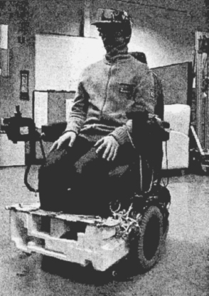
Figure 4.5. User with the cap interface on a wheelchair.
4.4.2 Implementation
Figures 4.6–4.8 show the bioelectrical signals we obtained from a user by using the three electrodes interface. The lower graph in each figure is the signal that directly picked up from the electrodes, whereas the upper one is the corresponding state of the wheelchair, which is driven by the user.
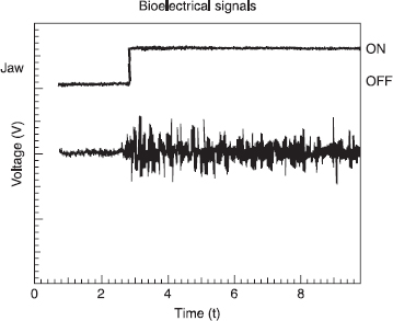
Figure 4.6. Activation of the JAW signal.

Figure 4.7. Activation of the LEFT signal.
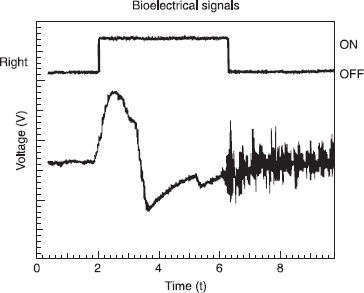
Figure 4.8. Activation of the RIGHT signal.
When the user is issuing a jaw motion command, both the electrodes at HI and H2 will detect the electrical activities from the jaw muscle, so that the resultant signal will oscillate at a very high frequency. When the user is looking to the left or right, a large potential difference will be detected at HI and H2: A negative change stands for the left, whereas a positive change stands for the right.
From the above results, we verify that the interface can detect three kinds of motions on the face: 1) looking to the left (L), 2) looking to the right (R), and 3) tightening the jaw (J). Since we have not applied any electrode along the vertical direction of the eye, eyelid movement such as blinking does not interfere with the signals in the H1–H2 electrodes pair. Next, we design the mapping between the states of the wheelchair and the actions produced by the users in Table 4.3. The difference between δ2–4 and δ5–6 is that the former one is to let the wheelchair turn slightly to the left/right (∼20o) while it is moving ahead, which is suitable in fine tuning the path that is traveling; the latter one is to make the wheelchair rotate at its center, which is suitable in turning some large corners. When the wheelchair is moving, either it is turning or moving straight ahead, the user can make a “STOP” whenever a jaw motion is generated. This can make sure that the user can stop the wheelchair motion actively to prevent any fault command from being made. The effects are demonstrated in Figure 4.7 and 4.8. In Figure 4.7, the user first looks to the left to trigger the “L” command; when he/she issues a jaw motion, the “L” state will be reset.
Table 4.3. Control mapping

4.5 EXPERIMENTAL STUDY
Several experiments are conducted to show the maneuverability of the wheelchair when the interface is treated as the main input device. The wheelchair platform that we are currently using is TAO-6 from Applied AI Systems, Inc., Ottawa, Canada. Most of the electronics are housed in a protective box beneath the seat. The sensors, joystick, LCD display and keypad are connected directly to the electronics box. There are a total of 11 infrared sensors, 8 ultrasonic sensors, and 2 bumpers for local obstacles avoidance. The system uses the Motorola mc68332 32-bit micro-controller as the CPU. All sensor inputs and the user interface are handled by this unit and additional input/output boards.
The experiments are designed to meet the needs of the daily activities that a disabled person might perform in an indoor environment [Figure 4.9, such as passing through doorways (A–B), U-turning from a dead-end (B–C–B), and general navigation (C–D)]. Figures 4.10, 4.11 and 4.12 show the result of each experiment we have conducted. The sampling rate of the data is 64 Hz.
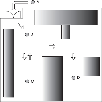
Figure 4.9. The floor plan of the experimental environment.

Figure 4.10. Experimental data for path A–B.
4.5.1 Doorways (A–B)
The task of passing through a doorway is an action that needs to be done everyday; whether the interface can enable the user to complete this task efficiently is a important concern. In Figure 4.10, the user is first issued a jaw command (J) to ask the wheelchair to move toward the doorway (δ2). When the user has reached the doorway, he stops the wheelchair and issues a left command (L), which lets it rotate to the left (δ5) until the heading is correct (t ≈ 4). Then, the user is issued a “J” again in order to pass through the door. At t = 6, when the wheelchair has approached the block near the door, the user stops the wheelchair and rotates to the left to get away from that obstacle. At the end, the wheelchair stops at B. The whole experiment takes about 10 seconds to complete.

Figure 4.11. Experimental data for path B–C.
4.5.2 U-turning (B–C–B)
This task demonstrates how a user can turn back from a dead end. Figure 4.11 shows the result of this experiment. From t = 0 to t = 4, the wheelchair proceeds straight ahead to C. After it has reached C, the user commands it to rotate (δ5) and then moves straight (δ2) to head for B again. Due to the hardware limitation and disturbance on the floor, the wheelchair cannot move straight ideally, so the user needs to issue “L” or “R.” to alter the path, for example, at t ≈ 2 and t ≈ 7.
4.5.3 General Path (C–D)
The last task is to travel from C to D; the result is given in Figure 4.12. It is interesting to note that the user does not need to stop the wheelchair to turn the first corner (at t = 2.5 to t = 4), only by executing a circular path for the wheelchair (δ4). The above results show that the interface we developed is efficient enough to navigate a wheelchair. All the tasks were achieved successfully without getting hit on any wall or obstacle during the experiments. Results also show that the users can command the wheelchair to move or stop effectively. By providing enough training for the user to use the interface, the user can navigate the wheelchair freely as he/she wishes.

Figure 4.12. Experimental data for path C–D.
4.6 CONCLUSION
This research is aimed at developing a simple, low-cost, yet usable assistive robotic wheelchair system for disabled people, especially those with a limb disability. The interface that is presented in this chapter uses a minimal number of electrodes to navigate a robotic wheelchair by eye-gaze and simple jaw motion. With the reduction in the number of electrodes required, the hardware is simplified and the whole device can be fitted in an ordinary cap. The experimental results demonstrate that a person can guide the wheelchair within an indoor environment efficiently by using the interface we have developed. With more robust autonomous modules to be added on this system, we believe that the interface will be an excellent alternative input device other than the tradition joystick control for people with a disability.
This chapter presents a preliminary stage of this research. One disadvantage of our approach is that the performance is very sensitive to the electrode placement and skin conductivity of each individual. However, once the calibration is done at the beginning, the device will become very stable and reliable. As a next step, we are going to develop a wireless communication between the wheelchair and the device. We will also use the device to cope with the autonomous control module of the wheelchair to perform various navigation tasks.
REFERENCES
1. R. Barea, L. Boquete, M. Mazo, E. Lopez, and L. M. Bergasa, “EOG guidance of a wheelchair using neural networks,” in Proc. of the IEEE 15th International Conference on Pattern Recognition, Vol. 4, pp. 668–671, 2000.
2. H. Yanco and J. Gips, “Preliminary investigation of a semi-autonomous robotic wheelchair directed through electrodes,” in Proc. of the Rehabilitional Engineering Society of North America Annual Conference, RESNA Press, pp. 414–416, 1997.
3. J. Gips and P. Olivieri, “EagleEyes: An eye control system for persons with disabilities,” in Proc. 11th International Conference on Technology and Persons with Disabilities, Mar., 1996.
4. R. J. K. Jacob, “Eye movement-based human-computer interaction techniques: Toward non-command interfaces,” Technical Report, Human-Computer Interaction Lab., Naval Research Laboratory, Washington, DC.
FURTHER READING
R. A. Cooper, “Intelligent control of power wheel-chairs,” IEEE Engineering in Medicine and Biology Magazine, Vol. 14, No. 4, pp. 423–431, Jul.-Aug. 1995.
L. A. Fried, Anatomy of the head, neck, face, and jaws, Lea & Febiger, Philadelphia, PA, 2nd ed., 1980.
Y. Kuno, T. Yagi, and Y. Uchikawa, “Development of eye pointer with free head-motion,” in Proc. of the Annual Int. Conf. of the IEEE Engineering in Medicine and Biology Society, Vol. 4, pp. 1750–1752, 1998.
S. H. Kwon and H. C. Kirn, “EOG-based glasses-type wire-less mouse for the disabled,” in Proc. of the First Joint BMES/EMBS Conference, Vol. 1, pp. 592, 1999.
G. Norris and E. Wilson, “The Eye Mouse, an eye communication device,” in Proc. of the IEEE 1997 23rd North-east, Bioengineering Conference, pp. 66–67, 1997.
R. C. Simpson and S. P. Levine, “Adaptive shared control of a smart wheelchair operated by voice control,” in Proc. of the 1997IEBE/RSJ Int Conf. on Intelligent Robots and Systems, IROS '97, Vol. 2, pp. 622–626, 1997.
H. Yanco, “Integrating robotic research: a survey of robotic wheelchair development,” in Proc. AAAI Spring Symposium on Integrating Robotic Research, Stanford, CA, Mar. 1998.
H. Yanco, A. Hazel, A. Peacock, S. Smith, and H. Wintermute, “Initial report on Wheelesley: A robotic wheelchair system,” in Proc. Workshop on Developing AI Applications for the Disabled, Int. Joint Conf. on Artificial Intelligence, 1995.
1 Reprinted, by permission, from Cedric K. H. Law, Martin. Y. Y. Leung, Yangsheng Xu, and S. K. Tso, “A Cap as Interface for Wheelchair Control,” in Proc. of IEEE/RSJ International Conference on Intelligent Robots and Systems, Volume 2, pp. 1439–1444, 30 Sept.–5 Oct. 2002. Copyright © 2002 by IEEE.
Intelligent Wearable Interfaces, by Yangsheng Xu, Wen J. Li, and Ka Keung C. Lee
Copyright © 2008 John Wiley & Sons, Inc.