Poly modeling generally takes one of two forms: low polygon-count modeling and high polygon-count, or organic, modeling. Because they require less memory, can be easier to animate, and can render quickly, low polygon-count models are useful in games. They can contribute to more realistic scenes by filling in background areas with less-detailed objects. An organic model's elements flow together seamlessly. Take the human head as an example; there may be no clear distinction between where the lower lip stops and the jaw starts or where the top of the nose ends and the forehead begins. A basic knowledge of anatomy and an understanding of balance and proportion are important when you're designing a character that is appealing and believable.
Realistic computer-generated (CG) characters are becoming very common in television and films; they appear as stunt doubles, masses of individuals, and even main characters. Using CG characters can often be safer and cheaper than using an actual actor or a stunt person and, at one time or another, most 3D artists strive to create a character they can call their own. This chapter focuses on using the Editable Poly toolset to create an organic alien model suitable for character animation. With the exception of the alien's eyes, the model is a single object created from a very basic form.
Topics in this chapter include:
Setting Up the Scene
Creating the Basic Form
Adding Detail
Final Touches
As mentioned in the previous chapter, acquiring and utilizing good reference material is essential for creating an adequate character in 3ds Max. At the minimum, sketches of the character's front and side features are necessary to use as background images. Additional perspective sketches from several points of view and sketches of specific features, such as headgear, weapons, or other devices should be near at hand during the modeling process for quick reference.
Like the Tank exercise in Chapter 5, "Modeling in 3ds Max: Part II," this exercise begins by creating crossed boxes and applying the reference images to them.
Open or Reset 3ds Max.
In the Top viewport, create a tall, wide box running along the X- axis.
In the Parameters rollout of the Command panel, set the Length to 0.01, Width to 66, and Height to 56.
Rename this box Alien Front Image.
With the box still selected, click the Move tool (


The box will move to the origin.

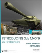
Create another box in the Top viewport. This one should run primarily along the Y- axis.
Set the Length to 20, Width to 0.01, and Height to 56 and then rename the box Alien Side Image.
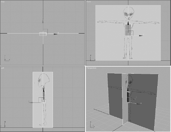
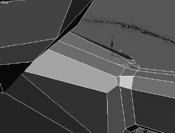
Move this box to the origin as well. The Perspective viewport should look similar to Figure 6.1.
The reference materials must be added to the boxes to provide a visual cue during the modeling process. It's important to ensure that the significant features of the character, which appear in both reference images, are at the same height. For instance, the top of the head and the shoulders should be at the same scene elevation to make the modeling process easier, eliminating as much guess work as possible.
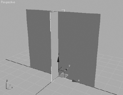
Click the Material Editor button (

Select the top-left sample sphere by clicking in it. This is the sample slot where you will make the front material.
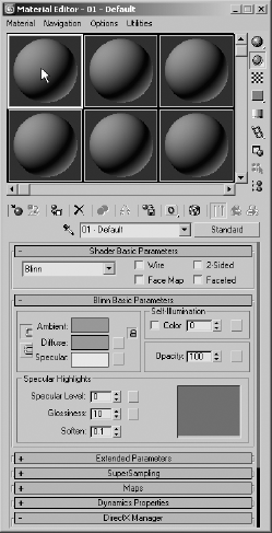
Expand the Maps rollout, and click the Diffuse Color button currently labeled None.
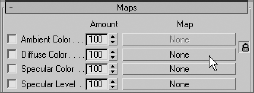
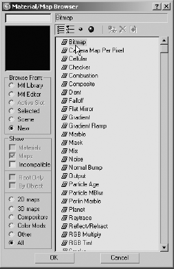
Double-click the Bitmap entry at the top of the Material/Map Browser that opens.

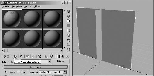
In the Material Editor's horizontal toolbar, click the Show Map in Viewport button. This causes the image map to be displayed in all viewports using the Smooth + Highlights display after the material has been assigned to the scene objects.

With the Alien Front Image box selected, click the Assign Material to Selection button in the Material Editor toolbar. The alien's front reference image will be displayed on the face of the box.
Note
Reference images should not be drawn on white paper before they are scanned to a digital file. By default, white is the color of selected objects in 3ds Max. They can be visually lost on a white background. If the drawings are on white background, use Photoshop, or another image-editing package, to process the images so the background is gray.
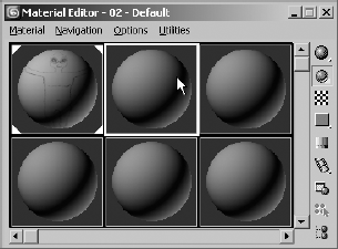
In the sample slot area, select the sample slot to the right of the current slot. Its boundary will turn white to indicate that it is the current material.
Seeing Quality Bitmaps in the Viewports
The Show Map in Viewport toggle (

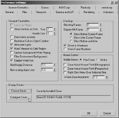
From the Main menu, select Customize → Preferences.
Click on the Viewports tab, and then click on the Configure Driver button in the Display Drivers section.
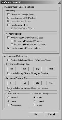
In the Configure Direct3D dialog box that appears, select a resolution in the Download Texture Size section or select the Match Bitmap Size as Closely as Possible option to increase the displayed resolution of any maps shown in the viewports. This does not affect the actual size of the images used in the scene, only how they are shown in the viewports.
If necessary, repeat Step 3 to increase the resolution of the background image in the Background Texture Size section.
Click OK in both dialog boxes to accept the changes. You must close and then reopen 3ds Max for the changes to take affect.
Be aware that increasing the displayed resolution can decrease viewport performance and increase the system resources required to manage the scene.
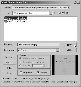
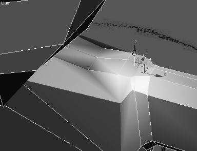
Repeat Steps 2 through 5, this time choosing the
Alien Sketch Side.jpgfile in the Select Bitmap Image File dialog box.Select the narrower box and click the Assign Material to Selection button. Your Perspective viewport should look like Figure 6.2. If the images do not appear in the viewport, right-click on the viewport's title and choose Smooth + Highlights from the pop-up menu to change the viewport rendering mode.
Close the Material Editor.

The alien character's form is pretty common: one head, one neck, two arms, a torso, and two legs. This is a frequently seen standard for bipedal, humanoid 3D characters. This form can be further refined by adding facial features and modeling the arms and legs into upper and lower segments with clearly defined fingers and toes, similar to the exercises in Chapter 4, "Modeling in 3ds Max: Part I."
When you create an organic character, you might be tempted to try to model one piece of the final product, such as the head or hands, to completion before you begin modeling another piece. This is rarely a good method because the scale and balance of the components must be built precisely from the beginning. A better practice is to block out the basic form and focus on the size and crucial shapes of major elements and then add detail for the finer features. The following exercises describe the steps required to block out the alien's major features.
The basic structure for the torso will begin with a simple box primitive. After converting the box into an editable spline, you will add the Symmetry modifier to the object so that any manipulations performed on one side are instantly performed on the other.

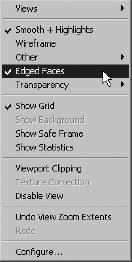
Right-click on the name of each Smooth + Highlights–rendered viewport and choose Edged Faces to display the rendered surfaces and the edges of each face.
In the Top viewport, create a box with two Length, Width, and Height segments. Rename the box to Alien and change its color, if necessary, to a hue that contrasts with the boxes that display the reference images.
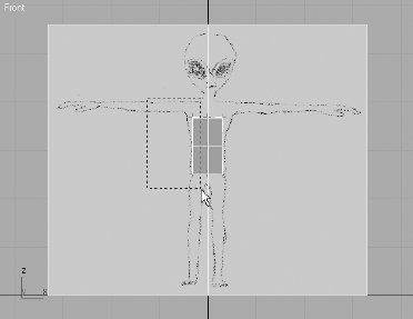
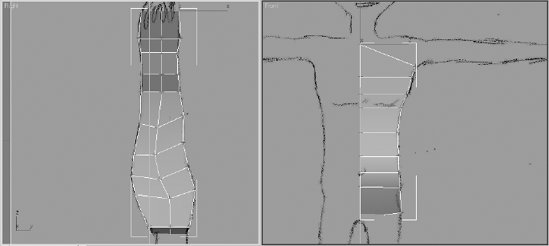
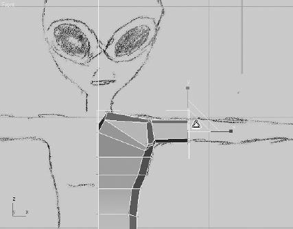
Move the box upward until it is centered on the torso in the reference images and modify its parameters to fit. It's better if the box is slightly smaller than the sketch so that the image is visible beyond the box similar to the box shown in Figure 6.3.
Convert the box into an editable poly object.
Access the Vertex sub-object level, and delete the left half of the box by dragging a selection region around the left-most vertices and then pressing the Delete key.
Exit the Vertex sub-object level. It's important that the next step occur at the object level.
Switch to the Modify tab of the Command panels and apply the Symmetry modifier to the box. The Symmetry modifier allows you to model only one side of the character while it automatically models the reciprocal side.
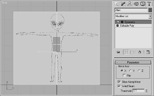
The box currently obscures the reference images and can make modeling more difficult. Turning on the See-Through mode in the object's properties will reduce this problem.
With the Alien object selected, right-click in the viewport and choose Object Properties from the Quad menu.
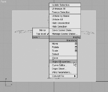
In the Object Properties dialog box that opens, check the See-Through option in the Display Properties section and then click the OK button. The object will become transparent in the viewports and the edges will remain visible.

You will begin forming the basic shape of the torso my moving the editable poly's vertices and extruding its polygons.
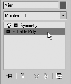
In the Modify panel, select the Editable Poly level of the Modifier Stack. The left side of the object will disappear. This will allow you to select vertices, with a selection region, in the Right viewport without selecting the vertices on the opposite side.

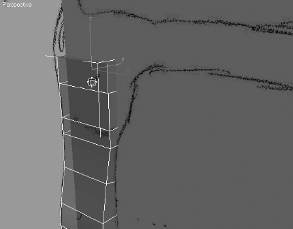
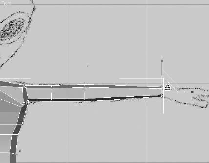
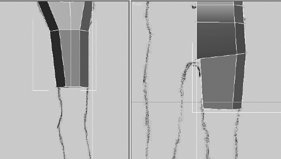
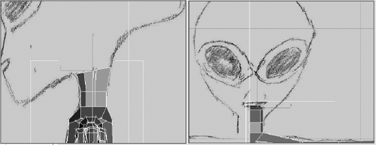
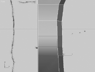
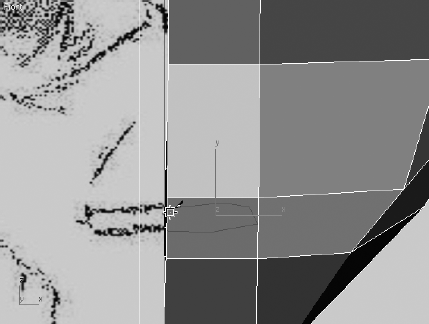
Access the Vertex sub-object level and start to form the torso by moving the vertices in the Front viewport to match the background image, as shown in Figure 6.4. Use a selection region to select both the front vertices and the vertices directly behind them.
Switch to the Right viewport and move the vertices to match the other reference image.

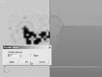
The alien's back has two curves; a concave curve at the lower part of the spine and a convex curve at his rear. The alien's front has a similar, more subtle compound curve. The editable poly object, however, does not have enough vertices to match the complexity of the image. The Chamfer tool is generally used to refine or soften an edge by subdividing it into two colinear edges, with new polygons located between them. The angle between the new polys and the old polys is one-half the previous value. When the polys on both sides of the edges are coplanar, no new angle is introduced to the model, but a gap is created between two new edges.
In the Selection rollout, click the Edge button (

Select the four edges that horizontally bisect the object. Switch viewports as necessary to select them all.
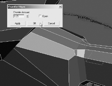
In the Edit Edges rollout, click the Chamfer button.
Click and drag on any of the selected edges to chamfer all of them.

Release the mouse button. Click and drag again to add two more rings of edges and further refine the mesh. Make sure that you do not drag so far that the new edges overlap.
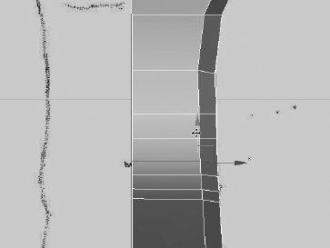
Switch back to the Vertex sub-object level and continue to move the vertices to match both the front and side reference images.

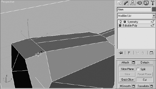
Switch to the Perspective viewport. Zoom and arc-rotate the view to see the top polygon in the model.
In the Polygon sub-object level, select the top polygons in the model and click on the Extrude tool in the Edit Polygons rollout. Be sure to select both the front polygon and the rear polygon hidden behind the box holding the front reference image.
Click and drag the top polygons to extrude them approximately one-third the distance to the alien's armpit. Release the mouse button and repeat the process two more times until the top polygon is even with the top of the alien's armpit.
Switch back to the Vertex sub-object level and move the new vertices to match the reference images. The inner pair of vertices should be higher than the other pair, causing the top edges to no longer be parallel to the others.

When you create models with the editable poly toolset, you will often generate unnecessary or unwanted polygons. In this section, you will eliminate some internal polygons that the model doesn't need.
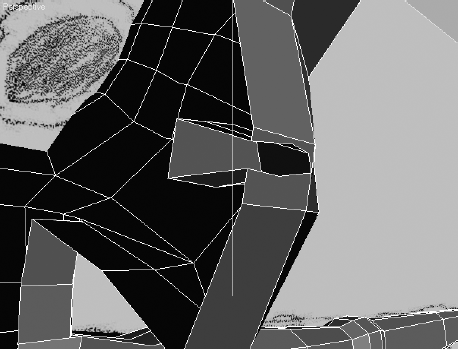
Continue from the previous exercise. Select all of the polygons in the model, right-click in the viewport, and choose Isolate Selection from the Quad menu. The two boxes will disappear and the torso will remain.
Arc-rotate the viewport to look at the inner surfaces between the two halves of the model. You will be able to see the six internal polygons created with the Extrude tool, as shown in Figure 6.5. You might need to turn off the See-Through mode to see these polygons clearly. These, and the six additional polygons created by the Symmetry modifier, are undesirable because they make the model unnecessarily complex and can affect later results when you use several of the Polygon Editing tools.
Select and delete the six internal polygons.
In Edge sub-object mode, select all the edges, front and back, from the alien's shoulder to its hip and then chamfer these edges. The new polygons created by the Chamfer tool will become the curvature around the sides of the alien.
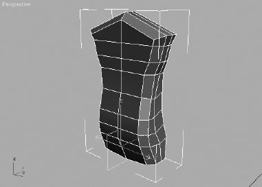
Exit the Edge sub-object level. Click the Symmetry entry in the Modifier Stack to see the model of the torso thus far.
Exit Isolation mode.

The next step in roughing out the basic form is to add the alien's shoulders, arms, and hands. The arms will be partitioned into a shoulder/clavicle element and an upper and lower arm. Modeling a character's hands was covered in Chapter 4, so we will only skim over it here.
Continue with the previous exercise or open the
Alien2.maxfile on the companion CD.
Select the Alien object, click the Editable Poly entry in the Modifier Stack, and access the Polygon sub-object level.
Select the four top polygons at the alien's shoulder area, including the chamfered polys.

In the Edit Polygons rollout, click the Settings button next to the Hinge From Edge button to open the Hinge Polygons From Edge dialog box.

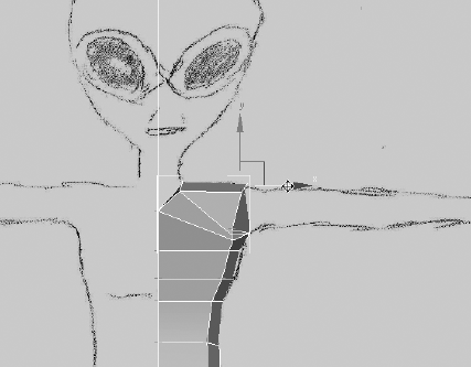
Click the Pick Hinge button and select either of the straight, horizontal edges near the armpit. The selected polygons will be previewed in the target orientation in the viewports.

Set the Angle value to about 17 and click the Apply button. The previewed orientation will take affect. The selected polys will be previewed rotating another 17 degrees about the selected edge. Click the OK button to accept the second hinge action and exit the tool. Your model should look similar to Figure 6.6.
Switch to the Vertex sub-object level and adjust the vertices to define the clavicle and shoulder area.
Note
Throughout the modeling process, you may find yourself turning the See-Through mode on and off to hide and unhide the background images and to isolate the model. The images in this chapter switch between these modes and practices as required. Press Alt+X to toggle See-Through on and off easily. Alt+Q will get you into (but not out of) Isolation Mode.
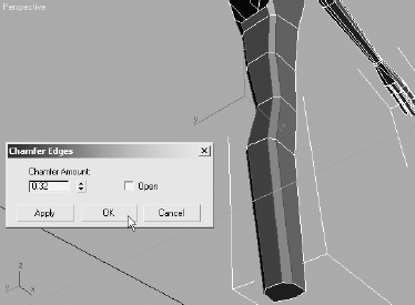
The Chamfer tool in the Edit Vertices rollout is similar to the same tool in the Edit Edges rollout. Rather than subdividing an edge into two colinear edges, it creates a new polygon by creating new vertices, projecting into all the polygons that share each selected vertex. If the arm were extruded now, it would be very boxy and would require the edges to be chamfered. By first chamfering the vertices, the resultant extrusion is more acceptable.
Zoom into the shoulder and select the four vertices at the corners of its perimeter. Click the Settings button (

In the Chamfer Vertices dialog box that opens, increase the Chamfer Amount to divide the angle between the perpendicular edges. Click the OK button when you are done.

There is a vertical edge that bisects the polygons that will be extruded to make the arm. If this remains, it will create undesired internal polygons. Selecting and deleting the offending edge would also delete the polygons that it contributes to the perimeter, and it would leave a hole in the model. The Remove tool, however, deletes the edge and combines the adjacent polygons into a single polygon.
In Edge sub-object mode, select the edge and click the Remove button in the Edit Edges rollout. The edge will be deleted and the perimeter will remain intact.

Select the polygon where the arm will be, and extrude it to about half the length of the upper arm.
Move the vertices to straighten the arm, and then select and scale all end vertices down slightly.
Repeat Steps 11 and 12 two more times, scaling the vertices up at the elbow and then down at the wrist.
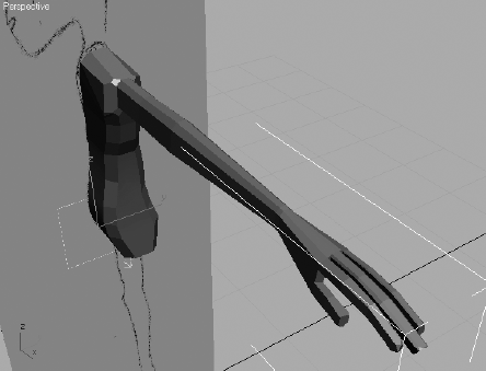
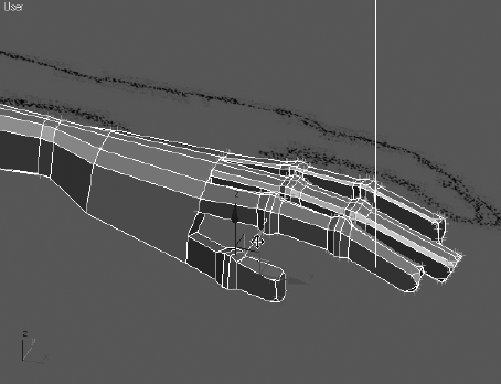
Similar to the modeling procedure described in Chapter 4 and here in Chapter 6, block out the basic form for the alien's hand. When completed, the hand and fingers should look similar to those shown in Figure 6.7.

To create the legs and feet, you'll use methods similar to the ones you used to create the arms and hands. Extrusions of polygons, chamfering of vertices and edges, and scaling vertices and polygons are all mainstays of polygonal modeling. In this section, you will also use the QuickSlice tool to add edges to polygons where additional detail is necessary.
Continue with the previous exercise or open the
Alien3.maxfile from the companion CD.
Hide the Alien Front Image object or move it behind the model so that it doesn't obstruct the view in the Perspective viewport.
Arc-rotate and zoom into the polygon that will be extruded to create the leg at the bottom of the model.
Select the edge that bisects the bottom polygons. Use the Remove tool to delete the edge.
Select the bottom polygon. In the Edit Geometry rollout, click the QuickSlice button. The cursor will turn into an arrow.

The intent here is to add an additional polygon near the centerline of the model to accommodate the detail around the crotch. Click on the edge in the front of the model that runs from the center to the side, near the symmetry plane that divides the model in half.
Move the cursor. A thin line that projects from the initial point through the tip of the cursor to the edge of the selected polygon will be selected.
Click in a similar location on the opposite edge at the back of the model. A new edge will appear, and the single selected polygon will be divided into two coplanar polygons.

Click the QuickSlice button to turn it off.
Select the larger polygon and extrude it about half the distance to the knee.
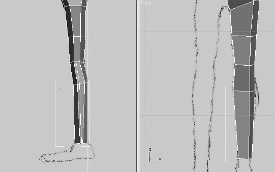
Select and then move and scale the vertices at the end of the leg to match the reference images.
Repeat the leg extrusions at the alien's knee, mid-calf, and ankle. Adjust the vertices at each location.
Arc-rotate so that you can see the inner portion of the leg. These edges are not chamfered like the edges on the outside of the leg. Select one inside-vertical edge at the front of the model and another at the back of the model.

In the Selection rollout, click the Loop button. Loop expands the selection to include all edges that meet, end to end, that are aligned with the selected edges.
Note
Instead of expanding the selection, you can use the spinner arrows, next to the Loop button, to shift the edge selection to the next aligned edges. The Loop tools at the other sub-object levels work in a similar fashion.
All of the inside edges, from the ankle to the crotch are selected. Use the Chamfer tool or the Chamfer Settings tool to subdivide the edges.
Now that the alien has a leg to stand on, you need to give him a foot. You'll continue using the Extrude and Chamfer tools along with the Hinge Polygons From Edge dialog box, as you did with the hand.
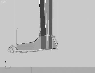
Continue from the previous exercise. Extrude the polygon at the base of the leg, until it extends to the bottom of the foot.
Select the polygon at the back of the foot and use the Hinge Polygons From Edge dialog box to create the polygons that make up the heel portion of the foot. Pick the edge at the top of the heel as the hinge. Click OK to close the dialog box.

Chamfer the edges of the polygons created with the Hinge From Edge tool, and then adjust the vertices as required.
Extrude the polygon, at the front of the ankle, twice to create the foot. The first extrusion is used to make the transition from the ankle to the foot and the second extends the foot to the beginning of the toes.
If the foot is pivoted incorrectly, select all of the vertices from the ankle down and rotate them until the foot points forward or slightly outward.

Continue to edit the vertices and edges of the feet to block out their basic forms.
Use the QuickSlice and Extrude tools, along with the transforms, to create the alien's toes and complete the leg.

The last major component to add to the model is the alien's head. In addition to the tools that have already been covered, the Cut tool, the Soft Selection method, and the Shaded Face Toggle option are added to your 3ds Max modeling toolset options.

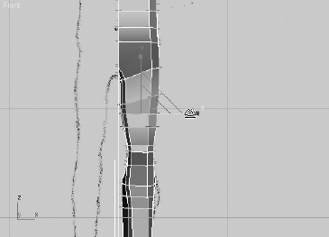
Zoom into the top of the model, where the neck will be. Select the vertices at the base of the neck, along the symmetry plane, and move them vertically as shown here.

Select the two polygons at the top of the neck and click the Z button, next to the Make Planar button in the Edit Geometry rollout. This will rotate all of the selected polygons until they are flush with the Z plane.

Select the edge that divides the top polygons and delete it with the Remove tool.

You will want to refine the edges of the neck that will be extruded to create the neck in the next step. The objective here is to reduce the angle of the intersecting edges at the corners of the top polygon by adding additional edges. Instead of chamfering the edges or vertices, click the Cut tool in the Edit Geometry rollout. Create a new edge by clicking at each point where you want the new vertices to be. Right-click to begin a new cut line. Click the Cut button when you are done.
Extrude the neck polygon and adjust its vertices to match both of the reference images. The alien's chin will drop well below the top of the neck in the side image.
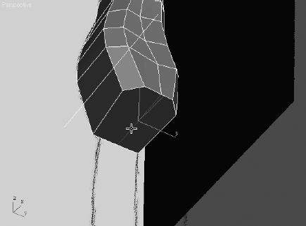
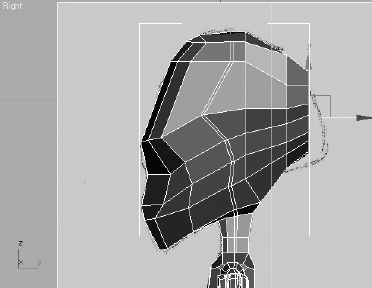
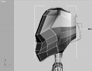
Using the Extrude tool, move the vertices as required to form the front and sides of the head so it will be similar to the model shown in Figure 6.8.
Extrude the polygons at the back of the head about half the remaining distance to the back of the head in the reference image, and then scale the vertices down a bit.
When sub-objects are moved, rotated, or scaled, the effect is applied explicitly and fully only to the selected sub-objects. This can result in a blocky, uniform appearance that is unappealing in an organic model. Soft selection lessens that effect by applying the transforms fully to the selected sub-objects and then, to a lesser degree, to the sub-objects that are in close proximity to the selection. The sub-objects that are closer to selection are more affected by the transform, and those that are farther away are less effective. When soft selection is used, 3ds Max color codes the selected sub-objects to provide a visual cue regarding how much of an affect the transforms will have. The colors range from red to orange to yellow to green to blue, with red sub-objects being fully affected and blue being unaffected.
In the Soft Selection rollout, check the Use Soft Selection option and click the Shaded Face Toggle button.
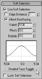
Increase or decrease the Falloff value until the non-blue colors extend to polygons at the side of the head.
Move and scale the end polygons to match the reference image.

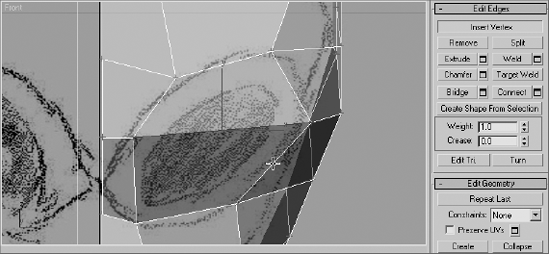
You can see that the head needs additional segmentation to match the reference image. We'll use the Connect tool to add that segmentation. The Connect tool adds edges to a model by subdividing pairs of selected edges.
Continue from the previous exercise. Turn off Use Soft Selection and switch to the Edge sub-object level.
Select any of the nearby horizontal edges on the side of the head that need to be subdivided.
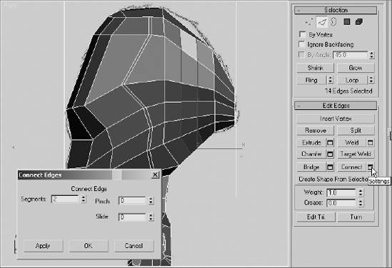
In the Selection rollout, click the Ring button. Similar to the Loop tool, the Ring tool selects all edges that are nearly parallel to the selected edge and lie along the same plane. All the horizontal edges that need to be subdivided are selected, as shown in Figure 6.9.

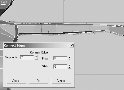
To open the Connect Edges dialog box, click the Settings button next to the Connect button in the edit Edges rollout. Set the Segments value to 2 and click the OK button. All of the selected edged are subdivided into three edges each.
Turn Use Soft Selection back on and reduce the Falloff value until only two rings of polygons, outside of the selected edges, show any colors other than blue.
Move the selected edges upward to match the reference image.
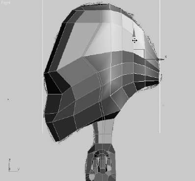
Continue shaping the head using the Connect option, Remove option, Soft Selection option, and some transforms to block it as desired.
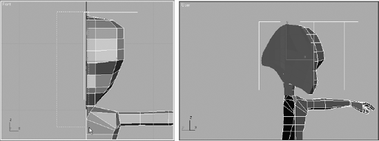
Many polygons were created on what will become the internal area of the head. They must be removed.
Access the Polygon sub-object level. In the Front viewport, use a window selection to select all the unwanted polygons and then delete them.

The basic form of the alien model is complete. Anyone looking at it can clearly see a humanoid character with a large head that slopes down in front and tapers in the back. In the next section, we'll cover adding details to the model, including a more-defined musculature, eyes, and a mouth.
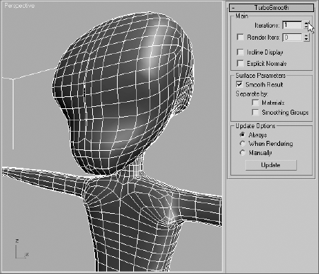
With the basic form blocked out, the alien needs to have detail added to define its appearance and make it unique among its peers. You'll start by adding the TurboSmooth modifier to subdivide and smooth the mesh, and then you'll continue the modeling process by working on the legs, arms, torso, and finally the head. TurboSmooth creates a nonrendering framework around the mesh, with its own vertices that can be weighted to control the localized deformation of the mesh.
The TurboSmooth modifier has two iteration options: Iterations and Render Iterations. The Iterations option determines the amount of smoothing the model has in the viewports. If Render Iterations is unchecked, Iterations also determines the amount of smoothing in renderings. When Render Iterations is checked, the amount of smoothing in renderings can be different, usually higher, than the smoothing shown in the viewports. This allows very dense models to be rendered, while less dense models are worked on in the viewports.
In this section, you'll apply the TurboSmooth modifier to the alien model to smooth its surfaces.

Exit any sub-object level, if necessary, and then select the Symmetry modifier in the Modifier Stack.
Expand the Modifier List and click the TurboSmooth modifier. The modifier appears at the top of the Modifier Stack.

Note
To quickly locate a modifier in the Modifier List, repeatedly press the letter key that corresponds to the first letter in the modifier's name. 3ds Max will select the first modifier that starts with that letter and then cycle through the list, selecting the next modifier that starts with that letter each time the key is pressed.
Set Iterations to 1 and make sure that Isoline Display is unchecked in the Main section of the TurboSmooth rollout. Isoline Display causes only the model's original edges to display, rather than all the edges in the newly subdivided mesh. When Iterations is set to a high value, this may be beneficial by reducing the complexity on the model in the viewport.
Note
Use caution when increasing the Iterations value. Dragging the Iterations spinner upward quickly, or entering a high value in the Iterations field, can cause Max to generate an enormous number of polygons that may exceed the memory capacity of your system, resulting in a crash. It is best to increase the Iterations value in increments of 1 until the minimum acceptable level of smoothing is obtained.
While remaining in the Editable Poly level of the Modifier Stack, you will need to see the smoothed result of your character throughout the modeling process. This is quickly accomplished by clicking the Show End Result On/Off Toggle button (
The legs need more detail, especially around the knee, to allow them to deform properly when they are animated.
Unhide any reference images and zoom into the area around the alien's leg.
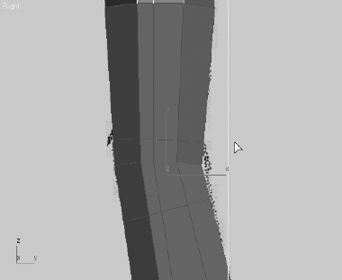
The knee is one area that needs additional detail to accommodate any deformations caused by animating with bones or Character Studio.
Select all of the polygons directly above and below the knee, and then use the QuickSlice tool twice, once above and once below the knee, to add additional segmentation. The angle of the slice plane should match the angle of the edges above or below the new edges.
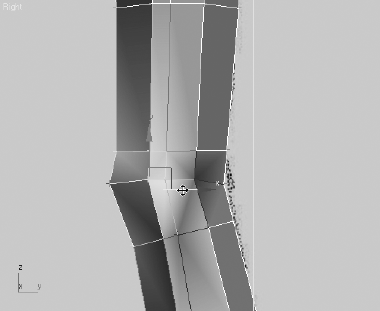
In Vertex sub-object level, select the vertices at the front of the knee. Turn on Use Soft Selection, and then reduce the Falloff value until only the vertices near the front of the knee are fully or partially selected.
Move the vertices forward to create the bulge of the knee cap.
Turn off Use Soft Selection and then use the Connect tool to further subdivide the edges in the calf area. Move the new edges so they are concentrated around the mid-calf area.
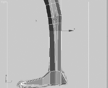
At the Vertex sub-object level, move and scale the vertices to sculpt the calf.

Do the same for the thigh area, making sure the vertices near the center do not cross the centerline of the model.
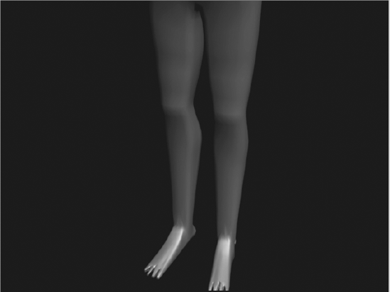
Use the tools discussed in this section to finish modeling the legs the way you want them. Using the Cut tool and then using the Bevel Polygons tool is an excellent method for modeling the calcaneus, the bone that protrudes from the side of the ankle. To make sure the edits are effective and generating the correct result, toggle the Show End Result button and render the scene frequently.

Zoom out and render the legs.
To allow proper deformation, additional detail must be added to the elbow area, in a manner similar to the way you detailed the legs. Additional musculature is also required in the arms and at the shoulders. Be sure to toggle the Show End Result button back and forth to see how the low-polygon modeling affects the final, smooth object.
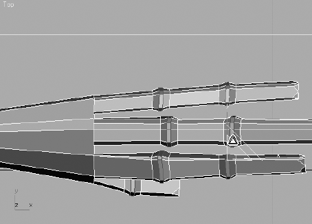
Select the vertical edges in the arm, from the bicep to the wrist, and use the Connect tool to add additional vertical edges to the arm, as shown here.
Move the new edges near the elbow, leaving one vertical loop of edges at the bicep and the forearm.
With Use Soft Selection turned on, move and scale the elbow until it is slightly larger than the arm.

Select the edge that defines the bulge of the bicep. With the character's hands oriented with the palms face down, the bicep should bulge forward and not upward.

The character has long slender fingers that tend to look like tubes or tentacles when the diameter of each segment is similar in size. To help define the individual finger bones, you need to increase the size of the knuckles.
Select all of the edges located at the alien's knuckles, including the thumb, and chamfer them twice. The second chamfer should concentrate two sets of edges closer to the centerline of the knuckles.

Select the inner pair of edges at each knuckle and scale the edges to increase their diameter.
If the knuckles appear to change the fingers' diameters too abruptly, turn on Use Soft Selection and scale them again along the X- axis only.
The hand tapers too smoothly from the wrist to the fingers, and there is no clear line of delineation between the forearm and the fingers. Use the QuickSlice tool to add an additional edge across the hand, and then move and scale it to define the hand better.

The thumb is tucked under the hand in an unnatural position. Select and move the vertices of the thumb and the inside heel of the palm forward and out from underneath the index finger.
Make any additional changes to the hand that you like. For instance, if the finger tips are too boxy in a smooth rendered image, move the vertices, near the end of the fingers, back a bit, or select and bevel the end polygons.
TARGET WELDING VERTICES
Having multiple vertices in close proximity can result in long thin faces that are difficult to deform, unacceptable folds or creases in the surfaces, and undesirable results when using the Bevel or Inset tools. These modeling problems are all common. They can be reduced or eliminated by welding the vertices. Standard welding, which is covered later in this chapter, replaces two or more selected vertices, within a specified distance from each other, with a single vertex located at the averaged location of the original vertex selection.
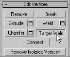
Target welding works somewhat differently. With the Target Weld button activated in the Edit Vertices rollout, you click the vertex to be eliminated and then click the target vertex. The original vertex moves to the target vertex, adjusts its associated edges and polygons, and is welded to it. The original vertex and target vertex must be separated by only a single edge.
The shoulder is currently flat from the end of the arm to the neck. In this section you will add the detail required to place a bulge at the top of the shoulder that tapers into the clavicle.
Continue from the previous exercise. Select and chamfer the loop of edges that runs over the shoulder and under the arm pit.
Select the three edges that run along the clavicle and use the Connect tool to add two more sets of perpendicular edges.
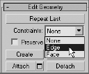
When Editable Poly sub-objects are moved in a viewport, they adhere to the same transform coordinate system restrictions as any other object in a scene. Similar to using the Local transform coordinate system, the Constraints option in the Edit Geometry rollout, allows you to limit the movement of the sub-objects to be parallel to the associated edges or polygons. This diminishes any unnecessary deformations caused by moving a sub-object away from a surface of the model.
With the four new edges selected, expand the Constraints drop-down list in the Edit Geometry rollout and choose Edge.
Move the edges closer to the shoulder. Note that they do not leave the plane in which they lie.
Change the Constraints option back to None.
Select the vertex at the top of the shoulder. Using Soft Selection, move it upward to create the shoulder bulge.
Zoom out and render the modeled arm; it should look similar to Figure 6.10.

The shape of the alien's torso is fairly plain, and decidedly not anatomically correct, so the detail added will be subtle. You will need to add some bulges for the wider hips and a belly button.

Zoom into the alien's hips, and select the three bands of horizontal edges that circle the alien at the waistline.
Chamfer the new edges. Using Edge Constraints, concentrate the edges around the hip area.
Turn the Constraints off and turn Use Soft Selection on. Then move the hip vertices into place.

Use the Cut tool to create the perimeter of the belly button and remove any internal edges that may occur.
Select the edges that encircle the belly button, omitting the edges along the center line of the model, and chamfer them. The chamfer prevents the next step from affecting the polygons and edges that are relatively distant from this small detail.
Select the polygon at the center of the belly button and move it into the alien's abdomen.

Besides the overall shape of the head, the two main features that must be considered are the eyes and the mouth. Without lips, a tongue, or teeth to consider, the mouth is the simpler of the two features to model; it consists of a mouth-shaped hole in the head. Rather than deleting faces, the mouth will be extruded into the head to prevent the appearance of a hollow skull.
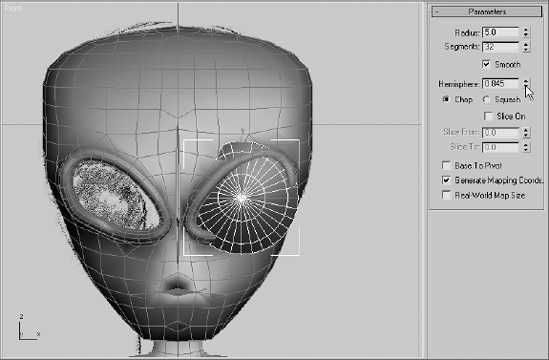
The areas surrounding the eyes are modeled using the Cut tool to define the shape and then Chamfer and Extrude to create the raised perimeter. The eyes themselves are spheres that are altered using the Hemisphere parameter.
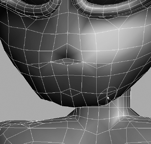
The mouth is going to be a simple extruded polygon, with the extrusion projecting into the alien's head. You'll create the perimeter of the mouth using the Cut tool.
Zoom into the mouth area.
Use the Cut tool to draw the edges around the perimeter of the mouth.
Use the Bevel Polygons dialog box to extrude and scale the polygon into the alien's head. A negative Height value causes the bevel to recess the polygon, rather than extrude it farther into the scene.

Select the edge at the center line of the mouth and delete, rather than remove, it to open that side of the mouth and eliminate any internal faces.
Start modeling the eye area by moving the vertices to cause the vertices to flow around the edges of the raised eye ridge.
To subdivide an edge at a particular location, switch to the Edge sub-object level. Click the Insert Vertex button in the Edit Edges rollout. Click on any edge to place a new vertex.
Continue to manipulate the vertices and edges until the eye area is a single, flat polygon. Select the eye polygon and use the Inset Polygons dialog box to create the ring of faces that surrounds the eye.

Delete the central eye polygon and then select all of the polygons that surround the new hole.
Bevel the selected polygons to create the eye ridge.

Rather than creating the eyes as components of the alien model, you will make them as separate objects that can be linked to the model. This method allows for greater flexibility when apply materials to, or animating, the eyes.
Exit any sub-object level. Create a sphere with a Radius of approximately 3 in the Front viewport.
Decrease the Hemisphere value until the visible boundary of the sphere is slightly larger than the eye hole.
Convert the eye to an editable poly. Rotate and move it to position it correctly in the eye socket.
Make any necessary edits to the vertices or edges to hide any portions of the sphere that protrude through the surface of the alien.
Exit any sub-object level. Rename the object Eye Left.
Click the Mirror tool (

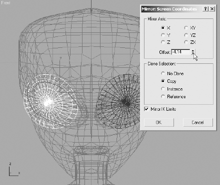
Rename the new object to Eye Right and make any changes required to make the eye fit in the socket.
Select both eye objects and link them to the Alien object to cause them to follow the alien's transforms.
The major portion of the modeling is complete. The only remaining tasks are to weld the seams, clean up any remaining areas with unwanted sharp corners, and add a few asymmetrical features so that the model does not look quite so computer generated.
Continue with the previous exercise or open the
Alien7.maxfile from the companion CD.
Hide the reference images if necessary.
Note
Before you proceed with the next step, you should always save a copy of the model or the entire scene, in case you need to edit it at the Symmetry or TurboSmooth level.
Select the alien and convert it to an editable poly.
Select all of the vertices that share the center line of the model or border an opening at the center generated during the modeling process. Make sure you don't select any of the vertices from the eye ridges that are close to the center line.

Click the Settings button, next to the Weld button in the Edit Vertices rollout, to open the Weld Vertices dialog box.
The Weld Threshold is the maximum distance that selected vertices can be apart before they are welded. Slowly increase the Weld Threshold value until the visible gaps are closed.

Examine the model closely, especially around the mouth and eyes. Make any corrections you like.
3ds Max uses a paintbrush analogy to reduce the sharpness, or tension, between adjacent polygons. Adjust the size of the virtual brush and click and drag over the areas to be smoothed.
In the Paint Deformation rollout, click the Relax button.

The brush will appear in the viewports as a circle with a line projecting from its center. The circle always remains parallel to the surface of the model. Reduce the Brush Size value to about 1.0.
To reduce the angle between the adjacent polygons, click and drag the brush over the areas to be smoothed.
Humans, animals, and many other living real-world creatures are basically, but not perfectly, symmetrical. The asymmetrical imperfections are natural and should be reflected in your models. The vertices around the eyes, the brow, and the mouth are areas to consider altering. The changes should be subtle and should not call attention to the varied area, unless that feature is significant to the character's makeup.
This chapter explored and explained several tools used to create organic models. From a simple box, a torso was formed to match the general shapes shown in the reference images. The Symmetry modifier required you to model only half of the character while it generated the reciprocal half. The legs, arms, and a head followed, all remaining in a simple boxy configuration. The TurboSmooth modifier was added to the top of the Modifier Stack to subdivide and smooth the polygons. Additional detail was added and then the model was collapsed and fine-tuned.
Although we used an alien character here, this toolset can be utilized for any type of organic model.