Applying materials is the phrase used in 3ds Max to describe applying colors and textures. Mapping is the term used to describe applying textures to materials (for example, adding wood grain to a wooden object). After you create your objects, 3ds Max assigns a simple color to them, as you've already seen. This allows them to render and display properly in your viewports.
To put it simply, a material defines an object's look—its color, tactile texture, transparency, luminescence, glow, and so on.
You define a material in 3ds Max by setting values for its parameters or by applying textures or maps. These parameters define the way an object will look when rendered. As you can imagine, much of an object's appearance when rendered also depends on the lighting. Applying materials and lighting go hand in hand. In this chapter and in Chapter 10, "3ds Max Lighting," you will discover that materials and lights work closely together.
In essence, how you see an object in real life depends on how that object transmits and/or reflects light back to you. Materials in 3ds Max simulate the natural physics of how we see things by how objects reflect and or transmit light.
Topics in this chapter include:
Materials
The Material Editor
Mapping a Pool Ball
Maps
Mapping Coordinates
Note
The first half of the chapter shows you the parameters and functions of the materials and the Material Editor window. If you want to skip ahead to work on a mapping exercise, go to the "Mapping a Pool Ball" section later in the chapter. Make sure you come back to skim over the hows and whys in the first half of the chapter.
Materials are useful for making your objects appear more lifelike. If you model a table and want it to look like polished wood, you can define a shiny material in 3ds Max and apply a wooden texture, such as an image file of wood, to the color of that material.
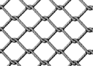
Materials also come in handy when you want to add the appearance of detail to an object, but without actually modeling it. For instance, if you want a brick wall to look like real brick, but you don't want to model the bricks in the wall, you could use a brick texture. Using a texture would be a time-saving alternative. You can plainly see a brick wall in Figure 7.1. However, in Figure 7.2, the wall shows the appearance of detail in each line of bricks using a texture map (called bump mapping). This texture map renders the appearance of dimension for each brick and the inset grooves between each of them, without the hassle of actually modeling the surface of the wall with that level of precision.
This shortcut is an easy trap to fall into. Using texture maps to accommodate too much detail can make your scene look fake and primitive. Don't depend on textures to do the work for you. A model that is not detailed enough for a close-up shot more than likely will not be saved by a detailed texture map. In the end, the level of detail that is needed boils down to trial and error. You have to see how much texture trickery you can use to keep a model's detailing at bay before the model no longer works in the shot. In the beginning, it's safe to assume you should model and texture as much detail as you can. You can work toward efficiency as you learn more about 3ds Max and CG.

Just as a model needs to be as detailed as the scene calls for, the same applies to texture maps. You will want to gauge the detail of your texturing based on the use of the object in the scene. A far away object won't need to have a massive texture map applied to its material. Textures mapped onto a material often add the final element of realism to a scene, and it takes a lot of experience to determine how detailed to make any textures for mapping. So let's start gaining some of that experience now.
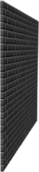
Figure 7.2. The same brick wall from an angle. The detail in the texture mapping of the wall was created with texture mapping.
What makes a material look the way it does? The primary force in a material is its color. However, there are several ways to describe the color of a material. In 3ds Max, three main parameters control the color of a material: ambient color, diffuse color, and specular color.
Ambient color is the color of a material when it is exposed to ambient light. This essentially means that an object will appear this color in indirect light or in shadow. Ambient gives you the very base color of the object, upon which you add the diffuse and specular colors.
Diffuse color is the color of a material when the object is exposed to direct light. Typically, the ambient and the diffuse colors are not too far apart.
Specular color is the color of a shiny object's highlight. The specular highlight on an object may be controlled by more than just its color—for example, its size and shape. The color, however, sets the tone of the object and, in some cases, the degree and look of its shine.
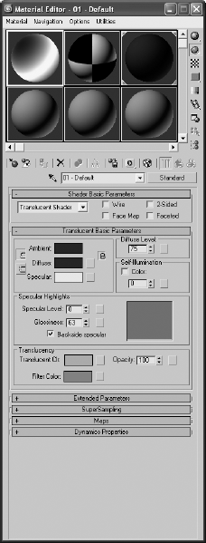
For example, in a new scene, open the Material Editor by choosing Rendering → Material Editor (Figure 7.3). The spheres you see in the Material Editor represent the materials in the scene. Each tile, or slot, represents one material that may be assigned to one or more objects in the scene. As you click on each slot, the material's parameters are displayed below. You edit the material through the settings you see in the Material Editor.
Select one of the material slots, and click it. Let's change the color of the material. Under the Blinn Basic parameters, click on the gray color swatch next to the Diffuse parameter. This opens the Color Selector window, as shown here.
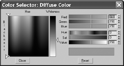
Using the sliders on the right, you can set the Red, Green, and Blue values for the color, or you can control the color using the Hue, Sat (Saturation), and Value levels. For more on color and RGB/HSV values, see Chapter 1, "Basic Concepts."
You can also very easily select the desired color from the gradient on the left by dragging your mouse over the colors until you find one you prefer. It's best to pick the general color you need from the swatch on the left and then tweak the exact color by using either the RGB or the HSV controls on the right. The Hue of a color represents the actual color itself. The Saturation defines how saturated that color is. The Value sets how bright the color will be.
Once you have a color you like, you simply close the Color Selector. If you want to restart the color, press Reset to zero out any changes. You'll notice that the ambient color changed as well as the diffuse color. You will see why in the next section on the Material Editor itself.
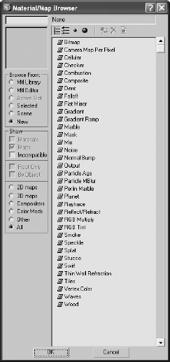
In addition, you can map textures to almost any of the parameters for a material. Notice the blank square icon next to the Diffuse color swatch. Click on that icon, and you will get the Material/Map Browser window, as shown here. The Material/Map browser is used throughout the chapter.
The Material Editor is the central place in 3ds Max where you do all of your material creation and editing. You create materials to assign to any single or group of objects in the scene. You can also have different materials assigned to different parts of the same object. In a full scene, it's customary to have several different materials
It is wise to get to know how the Material Editor works first, and then get to know the types of materials and shaders in 3ds Max. Open the Material Editor by choosing Rendering → Material Editor or by pressing the keyboard shortcut M. Figure 7.3 shows the Material Editor and its major parts.
The following list describes the functions of the Material Editor:

- Sample Window
The sample window provides you with a quick preview of your material. Each material is displayed on a sphere in one of the tiles (or slots) you see in the Material Editor window. Right-clicking on any of the materials will give you a few more options, including the ability to change how many sample tiles you can see in the Material Editor (as shown here). The fewer samples, the quicker the Material Editor will load.
- Get Material
This button brings up the Material Library browser. The Material Library stores a collection of saved materials that you can bring into the current scene. You can use 3ds Max's default materials or create your own and store them in your own custom library.
- Assign Material to Selection
You can use this button to assign the material to the selected object(s) in the scene. You can also apply materials by clicking and dragging the preview from the Material Editor directly onto the object in the viewport; however, this can be less accurate, especially if you have a lot of objects.
- Reset Map/Mtl to Default Settings
This function resets the values for the map or material in the active sample slot.
- Put to Library
You can save your material to a library using this function. Building up a library of useful materials can save time, especially when you're trying to re-create complex materials. Once you've gotten a material just right, there's no reason you shouldn't save it to your library by using this button.
- Material Effects Channel
Here you can assign an effect ID to the material. Effects are used in the video post or Combustion for things such as glow, highlights, and so on. Some of these effects will be covered in Chapter 11, "3ds Max Rendering."
- Show Map in Viewport
This will display your material in the viewport. This means that you won't have to render every time you want to see how your material appears on a 3D object. However, displaying your map in a viewport has limitations. The limitations are basically those of your graphics card and your chosen method of displaying 3D in the viewport (Open GL, Direct 3D, or Software). The difference between viewing the map in the viewport and in its final rendered state may be quite different. However, seeing a map in the viewport is useful on many levels.
- Go to Parent
Just as you created objects that related to each other, materials in 3ds Max may have several components to them (such as texture maps) that work in a hierarchy, where information from one node is fed upstream into the parameter for the material. When you are working with submaps, this option will take you back to the base material. This makes it easier to navigate in the Material Editor when you are editing your materials.
- Go Forward to Sibling
This function is the reverse of Go to Parent. This option will take you into the submaps levels.
- Preview Type
Sometimes the default sphere won't give you an adequate preview of the material. You can change the preview to a cube or a cylinder.
- Pick Material from Object
When you need to edit a material on an object, you can use this button to select the material from an object in the scene. The material is placed in the active sample slot.
- Material Name
This is a unique name for the material. 3ds Max will not allow any identically named materials, so make sure you provide a good descriptive name here.
- Material Type
Different materials have different uses. When called on to create a more complex material, for example, you can change the material type to Blend. A Blend material will mix the results from two different materials together for a compound effect. The default material type is Standard. Material types are explained in the next section.
- Shader Type
Shading types describe how the surface responds to light. How an object looks depends on how its surface reacts to light, so the Shader type for a material is very important. Shaders provide different options for specific materials. The default shader is Blinn. Shader types are covered later in this chapter.
- Miscellaneous Settings
These are fairly basic settings to change the appearance of the material. Here are the two more important settings:

- Wire
When you turn Wire on, the object attached to this material will render as a Wireframe object. This simple setting is very powerful; it's used when you need to render line art or Wireframe views.
- 2-Sided
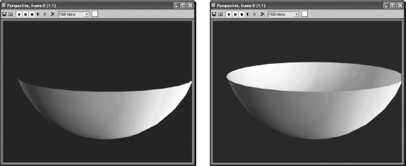
This setting enables you to render both sides of a single surface. By default, only one side of a surface will render, and that is typically all you need. Sometimes, however, when you penetrate through a surface, you will have to see the other side. In this example, a hemisphere is rendered without 2-Sided turned on, in the image on the left, and with 2-Sided enabled in the image on the right. Notice the inside of the hemisphere.
- Locks
Here you can lock the Ambient parameter to the Diffuse parameter and lock the Diffuse to the Specular. Any changes made to one while the locks are enabled affect both.
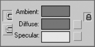
- Ambient, Diffuse and Specular Color
Changing the ambient color will affect the way the material appears for ambient light. Changing the diffuse color affects the overall color of the material. Specular color changes the color of the highlighted light. You change the color by clicking on the color swatch next to the parameter.
- Diffuse and Specular Maps
These buttons provide shortcuts to the maps for Diffuse and Specular. A map applied in Diffuse (for example: bitmap; i.e., an image file) will affect the base appearance of the material. A map applied to Specular will use the mapped image to define the color of the shine. Mapping is covered in the Pool Ball exercise later in this chapter.
- Specular Level
This setting determines how shiny the material appears. For something such as a metallic surface, the setting will be up around 180 to 220. You can also map a grayscale texture to determine which areas will appear as shiny and which will appear as dull.
- Glossiness
This setting determines the spread of the specular shine. A higher value means that it will look more plastic (high gloss across the surface of the model).
- Self Illumination
This slot defines how the material is affected by light. The more self illumination it is given, the less the material is affected by lighting, but the more flat it will become.
- Opacity
A material's opacity determines how transparent it appears. If it is set to 100 (the default), then the material is 100 percent opaque—that is, it's solid. If it is set to 0, then it is completely invisible. You can apply a grayscale texture map here to use a bitmap (or other map) to define which portions of the material are transparent. Areas of white on the map will be opaque, whereas the black areas will render transparent; the intermediate values of gray will have different levels of transparency.
- Maps
Maps allow you to apply bitmap textures, which are maps that help define the material beyond simple color and opacity settings. Common maps include bump maps (use grayscale values to simulate bumps and dents), displacement maps (use grayscale maps to mathematically calculate depth and height and redefine the mesh accordingly), reflections, glossiness, and so on, as shown in Figure 7.4.


Different materials have different uses. The Standard material is fine for most uses. However, when you require a more complex material, you can change the material type to one that will fit your needs. To change a material type, click the Material Type button called out in Figure 7.3. By default, it displays Standard in the button. Once you click the button, the Material/Map Browser window opens (as shown here) from which you can choose the material type.

Standard material is the default type for the materials in the Material Editor. This material has values for ambient, diffuse, and specular components. With it, you can imitate just about any surface type you can imagine. The more advanced surface types (see the following discussions) combine elements of different shaders for more complex effects.
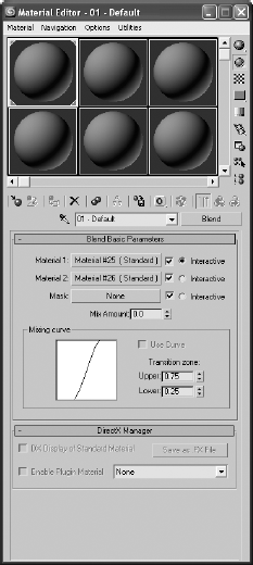
Just as it sounds, this material type blends two materials together. Figure 7.5 shows the parameters for a Blend material type. Notice the controls for mixing two different materials. You assign the materials through the Material 1 and Material 2 parameters.
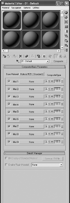
Similar to the Blend, a Composite material combines up to 10 materials, using additive colors, subtractive colors, or opacity mixing (Figure 7.6).
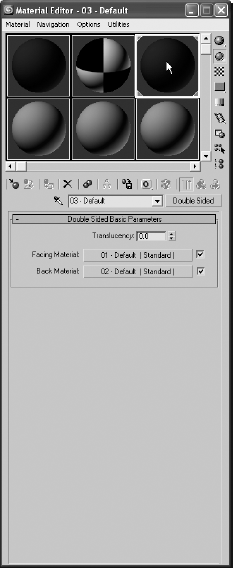
The Double Sided material type simply divides the material into two submaterials, one for the outward face and one for the inner face. Figure 7.7 shows the parameters for the material. To set the Facing Material, you can click on the bar to create and edit a new material, or you can click and drag an existing material from the Material Editor onto the Facing Material bar. You set up the Back material in exactly the same way.
In the following graphic, you can see how you can assign one material to the outer face of an object and another one to the back of the surface. Here, a bowl has a solid blue material mapped to the outside, and the inside face is a checkerboard pattern map.

Neither the facing nor the back material need to have 2-Sided enabled for the Double Sided material to render both sides of the surface.
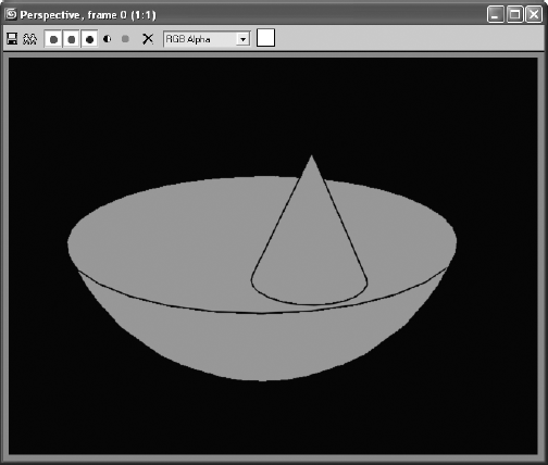
Ink 'n Paint is a powerful "Cartoon" material that creates outlines and flat cartoon shading for 3D objects based on Falloff parameters. Figure 7.8 shows the parameters for an Ink 'n Paint material. Figure 7.9 shows you a sample render with the Cartoon shading material applied to a bowl and a cone.
Use Matte/Shadow material when you want to isolate the shadow. The material will receive shadows, but remain transparent for everything else. It is useful for rendering objects onto a photo or video background because it creates a separate shadow that you can composite on top of the background. Rendering in separate passes, such as a separate shadow, is very useful because you can have total control of the image by compositing just the right amount of any particular pass.
Use this material when you need to apply different materials to portions of a 3D object that have different material IDs. You can then assign different surface treatments to a single object. This keeps modeling simpler because you do not have to make separate objects for everything that needs a different material.

The Raytrace material is a powerful material that expands the available parameters to give you more control over photo-real renderings. The material uses more system resources than the Standard material at render time, but it can produce more accurate renders—especially when true reflections and refractions are concerned. You will use this material in Chapter 11.
The Shellac material superimposes one material on another using additive composition. This allows you to create a material that is highly glossy, such as a finely varnished wood surface (Figure 7.10).
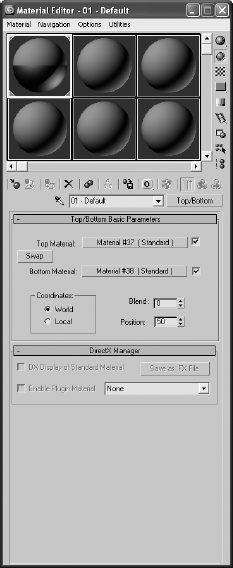
Top/Bottom divides the material into a top material and bottom material with an adjustable position (Figure 7.11). The material is in the first slot in the Material Editor in the figure. This material is useful for creating an object that has two different materials on either side, such as a cookie with chocolate on the top. Mmmm, cookie.
Note
Most of your work will probably be with the Standard material type, unless you are working with architectural files. You will need to change the material type only for special needs. However, you will need to change the Shader type more often to achieve certain surface qualities. You will explore Shader types next.
The way light reflects from a surface defines that surface to your eye. In 3ds Max, you can control what kind of surface you work with by changing the Shader type for a material. This option will let you mimic different types of surfaces such as dull wood or shiny paint or metal. The following descriptions outline the differences in how the Shader types react to light.
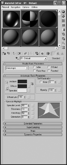
The Anisotropic shader (shown in the following graphic) is good for surfaces that are deformed, such as foil wrappers or hair. Anisotropic is defined as having properties that differ according to direction. This creates a specular highlight that is uneven across the surface, changing according to the direction you specify on the surface. The other surface types, as you will see in this section, typically create rounded specular highlights that spread evenly across a surface. Figure 7.12 shows the Material Editor for an Anisotropic material. Notice the extra controls for the specular highlights. These allow you to control how the specular will fall across the surface.
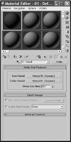
Figure 7.10. The Shellac material allows you to superimpose a shiny layer on top of another material

This is the default material in 3ds Max because it is a general-purpose, flexible shader. The Blinn shader (shown here) creates a smooth surface with some shininess. If you set the specular color to black, however, this shader will not display a specular and will lose its shininess, making it perfect for regular dull surfaces, such as paper or an indoor wall. Figure 7.13 shows the Blinn shader controls in the Material Editor.
Because this is the most-often used shader, let's take a look at its Material Editor controls. The ambient, color, and specular colors all work as you've seen earlier in this chapter. You simply set the color you want by clicking the color swatch, or you can map a texture map to any of these parameters by clicking the Map button and choosing the desired map from the Material/Map Browser window.
The parameters in the Specular Highlights section of the Blinn Basic Parameters rollout are interesting for this shader. The specular color, which defaults to white, controls the color of the highlight. Decreasing the brightness of that specular color, whatever the color may be, will decrease the brightness of the specular highlight on the object, making it seem less shiny. Changing the specular color to black will negate any surface shine.

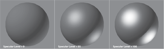
The surface shine is also regulated by the Specular Level parameter. The higher the value, the hotter the specular highlight will render on the object. Figure 7.14 shows a sphere with a Blinn with a Specular Level of 0 on the left, a Specular Level of 35 in the middle, and a Specular Level of 100 on the right.
The Glossiness parameter controls the width of the specular highlight. With the same sphere with a Specular Level of 35, Figure 7.15 shows you a Glossiness of 0 on the left (which creates a broad specular), a Glossiness of 35 in the middle (which creates a fairly tight, shiny specular highlight), and a Glossiness of 75 on the right (which creates a high gloss pin point specular highlight). The higher the value, the glossier the surface will appear.
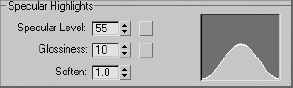
Finally, the Soften parameter controls the softness of the specular highlight. Figure 7.16 shows a sphere with a Blinn material assigned with a Specular Level of 55, a Glossiness of 10, and with a Soften value of 0 on the left and a Soften value of 1 (the max) on the right.

Soften controls the specular breadth on specular highlights that are already broad—that is, they have lower Glossiness values. You may want to look at these parameters at work in a Max scene, as your monitor will display the specular highlights better than a printed page.
You've probably noticed the graph (shown here) in the Material Editor when you work with the Specular Level, Glossiness, and Soften parameters. This graph shows you the falloff of the specular you are editing for the material. The shorter the graph, the lower the level of specular highlight. The rounder the graph, the broader and softer the specular highlight.
For shiny objects, you will need to use a fairly sharp specular. For extremely shiny objects, such as polished metals, a pinpoint specular is best. Plastic objects will work best with a broad, diminished specular. Matte objects, such as paper or cloth, work great without a specular highlight, or at least a very darkly colored one.
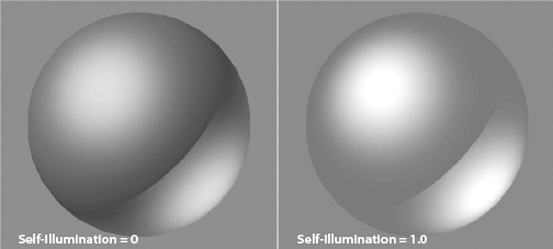
The Self-Illumination parameter adds incandescence to the material, as if the object is giving off its own light. The higher this value, the flatter the object will appear, because Self-Illumination will essentially negate any shadowing or ambient falloff on the material. The specular highlights on the material will still show up on a material with Self-Illumination turned all the way up to 1.0. You can also change the color of the Self-Illumination by clicking the Color check box and choosing a color in the swatch that appears when Color is enabled. This allows you to have a different incandescence color than the color of the material itself. Figure 7.17 shows a Self-Illumination value of 0 on the left and a Self-Illumination value of 1.0 on the right. Notice how the sphere flattens out as Self-Illumination helps keep the shadow areas as bright as the diffuse.

Figure 7.16. The Soften parameter helps reign in broad specular highlights by softening their edges.
Note
A Self-Illumination value does not emit a light in the default scanline renderer-that is, the object will not illuminate other objects in the scene. For such an effect, you will need to use more advanced rendering techniques with mental ray, for example.
Finally, the Opacity setting sets the transparency of an object, as you may have read earlier in the chapter. The higher the Opacity value, the more solid it renders. The lower the Opacity value, the more see-through the object will render.

The Metal shader is not too different from the Blinn shader. Metal creates a lustrous metallic effect, with much the same controls as a Blinn shader, but without the effect of any specular highlights. When you are first starting, it's best to create most of your material looks with the Blinn shader, until you're at a point where Blinn simply cannot do what you need. The following graphic displays a sphere with a Metal shader with a Specular Level of 120 and a Glossiness of 60.
The black areas of the shader may throw you off at first, but keep in mind that a metallic surface is ideally black when it has nothing to reflect. Metals are best seen when they reflect the environment. As such, this shader requires a lot of reflection work to make the metal look just right.
With some surfaces, you need complex highlights. In some cases, while an Anisotropic might be useful, you may need further control in the complexity of your specular shape and falloff. A Multi-Layer shader will stack two Anisotropic highlights together to give you increased control over the highlights you can create.

Here you can see a Multi-Layer material assigned to a sphere. The two layered specular highlights are created in such a way, as seen in Figure 7.18, to create an "X" formation for the highlight.
The Oren-Nayar-Blinn shader (shown here) generally creates good matte surfaces such as cloth or clay. The shader has specular highlight controls very similar to those of the Blinn shader.

By all accounts, the Phong shader (shown here) looks very similar to the Blinn shader, and it has the same controls. Phong creates smooth surfaces with some amount of shininess, just as Blinn does. However, Phong does not handle highlights as well as Blinn. This is especially true for glancing highlights, where the edge of a surface catches the light. Phong is good for creating plastic objects, as well as many other surfaces.


The Strauss material (shown here) can create metallic and nonmetallic surfaces. Its main controls are Color, Glossiness, Metalness, and Opacity. The specular highlights, for the most part, are governed by the Glossiness of the material. The higher the Metalness value, the darker the unlit portions of the surface become, again relying on reflections for the metallic look.

The Translucent shader (shown here) is very similar to the Blinn; however, this shader adds a touch of translucency to the material. Translucence is where light is scattered as it passes through the material—for example, a flashlight shining behind a parchment. You can also simulate frosted and etched glass by using translucency. Figure 7.19 shows the Material Editor for a Translucent shader material.

Let's put some of that hard-earned knowledge to work and map an object. You will be creating and texturing a pool ball. Although this may not seem the most exotic thing to texture, you can learn a lot about surfaces, shading, and mapping techniques by texturing it. You'll be able to flex your mapping muscles even more in exercises later in the chapter.
You can begin with your own project, or you can copy the PoolBall project found on the companion CD to your hard drive. It contains a texture image file you'll need for this exercise.
In a new scene, create a sphere. The size doesn't matter here. How's that for fast modeling?
Open the Material Editor by pressing the keyboard shortcut M or clicking the Material Editor icon (

In the Material Editor, select one of the sample slots. Go to the Blinn Basic Parameters rollout.
The most logical thing to start with is the color. The base color of an object is defined by the Diffuse parameter—although Ambient is also locked to Diffuse, which is fine. The Diffuse parameter is shown here.
Click on the color swatch to the right of the Diffuse parameter to open the Color Picker window. Pick any color at this point. Once you have chosen your color, click the Close button, and you will see that the sphere in the sample slot has changed to your color.
The next step is to decide what the surface of your object is going to be. Will it be shiny or matte? You will need a shiny surface, because real pool balls are glossy. We will have to adjust the specular highlights using the Blinn's controls.
Go to Specular Highlights under Blinn Basic Parameters. Set the Specular Level to 98 and the Glossiness to 85. Keep Soften at the default. The specular graph here is quite sharp.

That is it for the basic material. Now apply it to the object by dragging the material from the sample slot to your sphere in the viewport and release the mouse button. The sphere will change to the color you chose for the diffuse, and in the sample slots the corners will become outlined with white triangles as shown here.

Note
The corner triangles on a sample slot in the Material Editor mean the material is "hot" or applied. Before you apply the material, it is "cool" and there are no corners. This is the default. When the corner triangles are solid white, the material is "hot" and the object it is applied to is currently selected.
The material is now linked to the material on the object. If you were to change any of the parameters of the material, it would be instantly updated on the object. For the most part, once a material is applied it cannot be deleted—it can only be replaced with another material. You cannot go back to the default color of the original object.
Figure 7.20 shows you what the pool ball should look like, most noticeably its specular highlight. However, viewing in the viewport isn't the same as a rendered image. The viewport gives the lowest level of quality, and it should not be used to make final decisions on the look of your material. Instead, it should be used as a point of reference. Figure 7.21 shows this pool ball rendered. Rendering combines the materials, lights, shadows, and environments within a scene to create the final look. Rendering will be covered in detail in Chapter 11. Notice how much more detailed the specular highlight is in the render. To check your render, simply click the Quick Render icon (


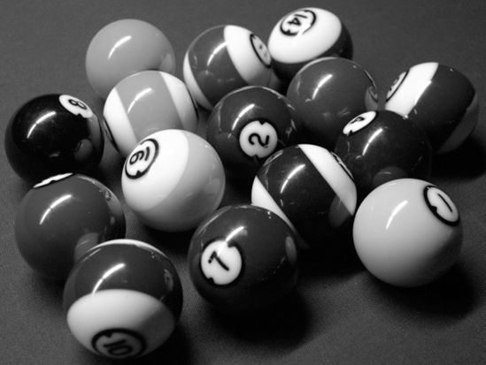
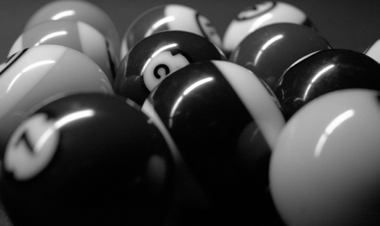
This simple material is only part of the story. You still need to add the markings of a real pool ball, not just a solid color. Just creating a sphere and making it shiny and green doesn't make a realistic ball. Figure 7.22 shows some real pool table balls. Pool balls have a graphic strip or number in a circle. You can't create this detail using the basic parameters of the Standard material. What you need is a bitmap.
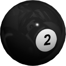
A bitmap replaces the diffuse color with an image. The image you use can be hand drawn and scanned, created in a program such as Adobe Photoshop, or taken with your digital camera. The image we are going to use was created in Photoshop (Figure 7.23). A white circle with a "2" is in the middle and then one that is cut in half is on either side. This has to do with texture placement. As you gain more experience, you'll learn how to prepare your texture images for your models.
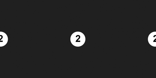
The theory behind this image is quite simple. Pool balls have the number on opposite sides of the ball. In your texture map, you'll need to make two 2s in the blue backdrop. The two halves of the white circle and the 2 will simply tile together when the texture image wraps around the sphere, much the way a wrapper wraps around a candy. Mmm85Candy. This way you have two 2s on the ball, easy as pie. To apply this bitmap as a texture, follow along here:
Go to the Material Editor and select the sample slot that is applied to the sphere. Go to the Maps rollout and click on the bar to the right of Diffuse Color, which is currently marked None. The Material/Map browser will appear.
Make sure the Browse From group is set to New. Select Bitmap and click OK, as shown here. An Explore window (Figure 7.24) will appear. Navigate to the map
PoolBallColorTexture.tiffile in the Sceneassets Images folder in the PoolBall project on the CD (or the one copied to your hard drive).
The Material Editor has changed, and you are in a separate module from the Material parameters. You are in the Bitmap parameter. There are several rollouts that we are going to ignore for now. The most important rollouts in the Bitmap section are Bitmap Parameter and Coordinates. The Bitmap Parameter rollout deals with the actual bitmap image; the Coordinate rollout controls how the bitmap image moves relative to the surface of the object. Leave all the settings at their default.
Note
If you ever need to change a bitmap image in a texture already applied, simply go to the bitmap's Material Editor and under the Bitmap Parameter rollout, click on the bar with the filename to the right of the Bitmap parameter. The file browser will reopen. Choose another image file, and it will replace the current bitmap file.
You will be able to see the bitmap in the sample slot, but not in the viewport. To fix this, click the Show Map in Viewport button (

Note
Think of the Material Editor as a literary outline. The heading of the outline is the full material, and its parameters when they are mapped (like Diffuse or the entries in the Maps rollout) are like an outline's subheadings that all fall under the main material.
Right now you can see only the Bitmap parameters. What if you want to go back and adjust the specular on the material itself? The Go To Parent button (

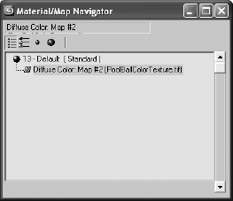
As a matter of fact, you can have an outline view of your materials. Open the Material/Map Navigator (Figure 7.26) with the Material/Map Navigator button (

The Material/Map Navigator is a floating palette; you can use it to navigate through your material and maps. This is very useful for complex materials that use a lot of maps. It is a very simple dialog: the blue sphere represents the material and its main parameters and the parallelogram is for the bitmap. The parallelogram is green by default and red when the Show Map in Viewport has been activated. Just click on the entry you need to show in the Material Editor to edit its contents.
Now render the ball to check the map's appearance. With your Perspective viewport active, click the Quick Render icon (the teapot). Figure 7.27 shows the pool ball with the mapping.


With the image applied, the pool ball looks pretty good at this point (Figure 7.27)—but it's not perfect. The small nuances are what really make a render look good. One thing this pool ball is missing is a reflection of its environment. Now, short of creating and texturing a pool table and several other pool balls, we need to make a cheat.
There are two ways to create reflections: the "cheat" method by mapping and using raytrace. Both methods require us to go to the Maps rollout in the Material Editor. We are going to add a bitmap into the Reflections Map slot. We are going to use the "fake it" method.
Note
Raytrace is a rendering methodology that traces rays between all the lights in the scene with all the objects and the camera. It can provide true reflections of objects in the scene. Chapter 11 covers raytracing in more in depth.
To fake the reflection, you'll need an image that looks like the "room" around the ball. We are going to use a photograph taken for this occasion and saved as the image file ReflectionMap.tif in the Sceneassets Images folder of the PoolBall project on the companion CD (Figure 7.28).
This image has all the elements that you might see around a pool ball—specifically, more pool balls! To add this image as a reflection for the ball, follow these steps:
Go to the Material Editor and make sure you are at the material's parameters; use the navigator or Go to Parent button if you are still in the diffuse bitmap area where you applied the image file.
Go to the Maps rollout and click on the bar currently marked None next to the Reflections parameter. Select Bitmap from the Material/Maps window, and then navigate to
ReflectionMap.tifin the Sceneassets Images folder of the PoolBall project on the CD, or on your hard drive if you've already copied it.Do a quick test render with the Quick Render icon (the teapot). The reflections are pretty strong (Figure 7.29).
You need to adjust how much reflection is on the ball. Click the Go to Parent button, and go to the Maps rollout. The type-in area next to the names lets you specify the amount of map applied to the material. Change the value next to Reflections from 100 to 10. Test render the pool ball again. You should notice a much nicer level of reflection (Figure 7.30). Voilà!

Note
If you have lost the view of your pool ball somehow, or if you simply want to center it in the Perspective viewport (or any other viewport), simply press the Z shortcut to focus the viewport on all the objects in the scene. In this case, it will center the pool ball.
You may notice that the background in the renders in Figures 7.29 and 7.30 are white, whereas your renders' backgrounds are probably black. A simple setting change and there are many reasons why you would want to control this option. You may want a specific color to offset your scene (for example, blue to represent the sky) or you may want a picture in your background.
To change the background of your renders, go to the main menu and choose Rendering → Environment (shown here). The Background parameter is at the top of the dialog box. Click on the color swatch and choose your color. That's it!
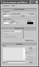
To add an image to the background, click on the bar marked None to add a bitmap, just as you did with the bitmaps on the pool ball. Once you do, the image will render in the background with your scene. To change the image, click on that bar, which at that point should list the path and filename of the current image, to take you to the Material/Map browser where you can select a new bitmap and image.
Now that you know how to add maps to a material, removing them is very simple. In the Material Editor for the parent material's parameters (not the map's parameters), you can right-click on the map name, as seen in Figure 7.31, to select Clear from the context menu.
If you don't want to clear the map entirely, but just need to turn it off for a little while, you can just uncheck the box to the left of the parameter name, as shown in Figure 7.32. Check it back on to use that map again.


If you have a scene with several materials, and you need to see more sample slots than the default in the Material Editor, simply right-click on any slot and select either 5 × 3 Sample Windows or 6 × 4 Sample Windows from the context menu. This will help you navigate a heavy scene that has tons of materials that you need to modify. In the following graphics, you can see the sample slots multiply!

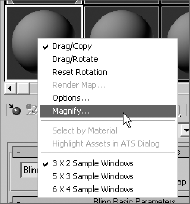
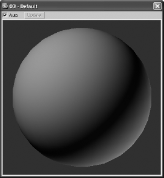
As you've seen, the sample slots for any given material in the Material Editor constantly update to show you any changes you've made to that material. However, if you want a larger image than the relatively small sample slot, right-click on the slot and select Magnify from the context menu, as shown in Figure 7.33. 3ds Max will open a larger window (Figure 7.34), which is resized by dragging the corners of the window, with a sample of that material. It will by default update automatically as you make changes to the material.
You've already noticed that there are only 24 sample slots in the Material Editor. This does not limit the number of materials you can use to 24. You should consider the Material Editor as a scratchpad of sorts. You can create as many materials as you'd like in a 3ds Max scene; however, at any one time, only 24 can be loaded in the Material Editor window at the same time.
If you click the Get Material button in the Material Editor, you can list all the materials that are used in the scene. When the Material/Map browser is open, click the Scene radial button for the Browse From parameter, and all of the materials assigned in the scene will be listed. When an object's material is not shown in a sample slot, it does not mean it has been deleted. You can load it back into any sample slot for editing at any time.
You've seen several times how to assign a material to an object. You can, for instance, drag the material from the Material Editor to the object in a viewport. You can also select an object in the viewport, and then select a Sample Slot material and click the Assign Material to Selection button (
However, you may want to assign materials to sub-object polygons as well as whole objects. One approach is to use the Multi/Sub-Object material type briefly discussed earlier in the chapter (the Multi/Sub-Object material will not be covered in this book, as it is beyond the beginner scope).
There is a much easier way to assign materials to sub-objects, however. Just select the appropriate polygons on the surface (the object must be an editable mesh or poly, or have an Edit Mesh/Edit Poly modifier applied), and assign the material as you regularly would (with the Assign Material to Selection button or drag the material to the selected polygons in the viewport). A sphere with several polygons assigned to different materials is shown in Figure 7.35.
Once you apply a material to a sub-object, a new Multi/Sub-Object material is created in the scene automatically. You can load the new Multi/Sub-Object material by using the eyedropper to click on the object in the viewport to load the material into a sample slot.

By now you've noticed that the Material/Map browser has different maps you can access. These maps are divided into categories.
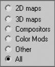
Open the Material/Map browser. The categories are listed on the left. By default, All is selected as shown here. You've already used the bitmap map a few times. Let's take a look at the rest of the maps by category.
The categories and their more important maps are explained in the following sections.
2D maps are two-dimensional images that are typically mapped onto the surface of geometric objects or used as environment maps to create a background for the scene. The simplest 2D maps are bitmaps; other kinds of 2D maps are generated procedurally.
Procedural maps are generated entirely within 3ds Max and rely on a set of parameters you set for their look. Images brought in the way the pool ball's color and reflection maps were brought in are not procedural. They are bitmaps —that is, raster image files. For more on raster image files, see Chapter 1.
Click on the 2D Maps category in the Material/Map browser to see the available 2D maps.
As you've already seen, a bitmap is an image file that you load into 3ds Max. It can be a photo, a scan, or any image that is readable by 3ds Max.
A procedural map, the checker map is a checkerboard pattern that is generated in 3ds Max. Its parameters in the Material Editor, which are shown here, control the look of the checkerboard. A sphere is also shown with a checker applied to its color.

The Tiling values under the Coordinates rollout determine the number of checkers. The higher the number, the more checkers. Color #1 and Color #2, of course, control the two colors of the checkerboard; black and white are defaults. Click on the color swatch to change the color, or you can click the Maps bars next to each color (labeled None until you assign a map). Also, the Blur parameter allows you to blur the edges of the checkers, and the Soften parameter under the Checker Parameters rollout blurs the checkers together.
A gradient i s a procedural map (the parameters are shown here) that grades from one color to a second color that grades to a third color. Here, a cylinder is shown grading from black (top) to white (bottom).

In the Coordinates rollout, the parameters are much the same as they are for the Checker map. These coordinates are pretty much the same for all procedural maps, as they allow you to position the map as you need on the object by setting the options such as Tiling and Offset.
The colors for the gradient are set by Color #1, Color #2, and Color #3. You can also map these colors. The Color 2 Position parameter sets the relative location of the middle color to the upper and lower colors—i.e., 0.5 is the middle because the other colors are at 0 and 1.0.
Similar to the Gradient map, but much more powerful, the Gradient Ramp is a procedural map that allows you to grade from and to any number of grayscale shades. Here, a gradient is shown in the Material Editor that is applied to a cube.

Use the sliders along the ramp in the Material Editor to set the position of the gray value. Click in the ramp to create a new slider at that grayscale value. The Black and White sliders at the very ends do not move. To delete a slider, right-click on it, and choose Delete from the context menu that appears. Notice the value and position readout above the ramp.
Gradient Ramps are perfect for creating maps that fall off (for example, for opacity affects where the opacity fades away).
Similar to 2D maps that are generated in two dimensions, 3D maps are patterns generated procedurally in all three dimensions. For example, Marble has a grain that goes through the assigned geometry in X, Y, and Z. If you cut away part of an object with Marble assigned as its texture, the grain in the cutaway portion matches the grain on the object's exterior.
When you create a 3D map, notice that the Coordinates rollout has Tiling and Offset parameters in three axes, whereas the 2D maps only have X and Y.
Try using some of the 3D maps (such as Marble, Wave, Stucco, and Wood) to see how they work on a simple object in your scene. They all have basically the same Coordinates rollout; however, each has its own Parameters rollout to control the color and other settings.
A Marble map creates veins of colors that run through an object. The 3D aspect of the map allows it to spread across all three dimensions, creating a more realistic texture. Color #1 and Color #2 control the two colors of a Marble map, while the third color is a grainy blend of the two together.
The Marble map's parameters are shown applied to a cube, which is also shown here.

Noise is a great way to easily add some randomness to a parameter or to add a bit of randomness to a surface's color or specular highlight, for example. Its parameters and a sample cylinder are shown here.

Used sparingly, noise can add great detail to highlights for any shiny object when mapped to the specular color. In this case, just make sure the colors in the noise do not contrast too much against each other, which would make the map faint.

Compositors are meant specifically for compositing colors or maps together for some advanced effects. In image processing, compositing images refers to superimposing two or more images to combine them in a variety of ways.
Color Modifier maps alter the color of pixels in a material for some advanced effects. Color modifiers and Compositor maps will not be covered in this book.
In a previous exercise, you turned a boring old sphere into a pool ball using Diffuse and Reflection maps. Now let's look at two important mapping techniques with the Material Editor.
To begin, you will create a chess piece (Figure 7.36) to learn about bump mapping and using reflections to create the illusion of shine and dents on the surface of the object. Just follow these steps:
Open the
Chess Piece.maxfile in the Texture Scene Files folder on the companion CD.
In the Material Editor, create a Standard Blinn material that has a red Diffuse Color with the these approximate values in the Color Picker window: Red: 200, Green: 15, and Blue: 0.
Even though the Chess Piece model in the scene may look red in the file you loaded from the CD, it does not have a material applied. That color is simply the color of the object set through the Name and Color text box at the top of the Modify panel. So, apply your Red material to the chess piece model. Click the Quick Render button, and you'll be able to see that this doesn't look anything close to a real chess piece (Figure 7.37).


Note
For an added treat, why don't you try to model the pawn chess piece itself for this example. You could also try to model different chess pieces, such as a rook or a knight.
The next step to making this piece more realistic is to add shininess, which you will accomplish in two actions.

Go back to the Material Editor. In the Material, change the Specular Level to 95 and Glossiness to 90. Your sample material should have a nice specular, as shown here.
The second part to making the piece shinier is to add a touch of reflection. Go to the Maps rollout and select the bar next to Reflection. You are going to add a bitmap to fake a reflection, as you did with the pool ball earlier in the chapter. In the Material/Map browser, select Bitmap.

Choose the
Reflect Map.tifimage. When you map a reflection, it is important to find an image that will be believable in your scene. Ideally, it should be the room around the object. In this case, you just want a little something to reflect faintly in the chess piece.Select the Go to Parent button (


Bump mapping is very common in CG. It adds a level of detail to an object fairly easily by creating bumps and grooves in the surface and giving the object a tactile feel in its appearance.
Bump mapping takes the intensity values of an image or procedural map to simulate bumpiness on the surface of the model, without changing the actual topology of the model itself. You can create some surface tactile texture with a bump map; however, you will not be able to create extreme depth in the model. For that, you may want to model the surface depth manually or use displacement mapping. Displacement maps are not covered in this book because they are a more advanced mapping technique.
Note
Displacement mapping is used to change the topology of the model, whereas bump mapping uses light and dark in the colors of the render to trick the eye into seeing surface detail.
To apply a bump map to the chess piece, follow these steps:
While still in the Maps rollout for your chess piece material, click on the bar labeled None next to the Bump. We are going to use another Dent map. Select Dent from the Material/Map browser. Change the Size to 400 and change the Strength to 2.0. Do not change the colors because you want the map to be black and white. Bumps work best when you are using high-contrast maps. Leave all the other parameters at their defaults. Quick render your scene and your chess piece should look like Figure 7.40. You can play around with the Size and Strength and Iterations to achieve different looks.
Click the Go to Parent icon to get back to the Material parameters and go to the Maps rollout. You can play around with the Bump amount until you have an acceptable result. Also, remember that the amount of bump you use will also depend on how close the object is to camera. The farther away an object is, the less visible the bump will be.
Let's try a slightly different look now using the following steps:
Go to the Material Editor. Select the red plastic material you created in the previous exercise.
Click the Go to Parent button to get back to the Material parameters and go to the Maps rollout.
Select the bar labeled None next to the Diffuse Color. Navigate to where the maps are and select
Wood1.jpgfrom the Texture Scene Files folder on the CD. This bitmap image will replace the red diffuse color. You won't see the change in the viewport until you select the Show Map in Viewport icon (
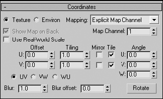
Render and you will see that the wood image has wrapped itself around the chess piece. You can edit the image through the Coordinate rollout (shown here) in the Bitmap parameters. Offset U will move the image horizontally. Offset V will adjust it vertically. Tiling scales the image, and Angle will rotate it across the surface.

Later in the chapter, you will learn a more efficient way to edit the image on the object, known as UVW mapping.
Opacity mapping allows you to cut out parts of an object by making those parts invisible. You can also create wonderful fading effects using Opacity maps. With opacity mapping, you don't have to model certain details, which can be a real time saver. In this example, you will create a chain link fence. However, you will not model a fence. You will create it entirely from mapping. To make a chain link fence, follow these steps:

Go to the Coordinates rollout and change both the U and V Tiling parameters to 3.0. This will scale down the image because the image repeats three times.
Apply the Material to the Plane geometry in the scene. Click the Show Map in Viewport button. Render and you will see something similar to Figure 7.42. As you can see, the Chain Link image appears on the plane, but you can't see the objects on the other side.
Go to the Material Editor. Click the Go to Parent button to get to the Maps rollout for the parent material. Click on the bar next to Opacity and select Bitmap from the Material/Map browser. In the Explore window, navigate to the Texture Scene Files folder on the CD and select
Chain Link OP.tif(shown here).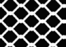
The tiling values for the Opacity map must be the same as the diffuse map; otherwise the transparency of the fence will not line up with the links of the fence. Go to the Coordinates rollout, and change both the U and V Tiling to 3.0. Render to see the results shown here.


You can see immediately how useful opacity mapping can be. 3ds Max uses the white portions of the image map to display full opacity, whereas the black areas become transparent. If you did not have an opacity file such as the one in this exercise, you could easily create one by painting a black-and-white matte of the color image that you are using for the material.
An image map is a two-dimensional entity that has length and width but no depth, while geometry in 3ds Max extends in all three axes. How is a material, which contains 2D image maps, applied properly to a scene object? Are the maps projected in a single direction onto the object's surfaces or do they envelop the object cylindrically or spherically? The answer depends on the type of mapping coordinates applied to the object. Mapping coordinates define how and where image maps are projected onto an object's surfaces and whether the maps are repeated across those surfaces.
Mapping coordinates are applied to objects in several ways. When primitive objects are created and the Generate Mapping Coords option is checked, at the bottom of the Parameters rollout, the appropriate mapping coordinates are created automatically. The Generate Mapping Coords option is on by default.
Loft objects, which are covered in Chapter 5, control mapping in the Mapping section of the Surface Parameters rollout. The Length Repeat value determines how many times the material's maps are repeated along the length of the Path object, and the Width Repeat value determines how many times the maps are repeated around the shape object. The configuration of the shape or path object is irrelevant to the application of the mapping coordinates; the loft object can create mapping coordinates for any loft object. Figure 7.43 shows a loft object with a simple checker pattern repeated five times along the object's length and three times around the perimeter of the shape.

Note
Objects that have been collapsed or converted to editable polys, editable meshes, or editable patches do not have inherent mapping coordinates. They must have the UVW Map modifier applied to utilize mapped materials.
The UVW Map modifier is a common method for applying and controlling mapping coordinates. You select the type of mapping projection, regardless of the shape of the object, and then set the amount of tiling in the modifier's parameters. The mapping coordinates applied through the UVW Map modifier override any other mapping coordinates applied to an object, and the Tiling values set for the modifier are multiplied by the Tiling value set in the assigned material.
Now let's take a look at how to apply a UVW Map Modifier in a scene. The following exercise examines the use of the UVW Map modifier:


MAPPING COORDINATES AND BOOLEANS
Boolean compound objects handle mapping in their own unique ways. When only Operand A has a mapped material, that material and its mapping coordinates are inherited by the resultant Boolean object. When only Operand B has a mapped material, the option of applying that material and mapping appears in the form of a dialog box. When both operands have mapped materials, the Material Attach Options dialog box presents several options to use or discard the materials and mapping.
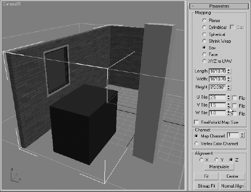
Open the Material Editor and then assign the Brick Wall material to the wall object. The material appears on the object in the Camera01 viewport.
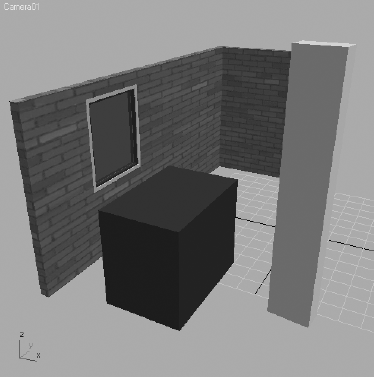
The problem is that the long wall is approximately 17 feet long and the short wall is approximately 7 feet long, and the Brick map used in the material is only eight bricks wide. The default mapping coordinates for a wall object applies the entire map to any vertical surface of the wall, regardless of how long that wall is. The long wall has eight bricks stretched along its length, just as the shorter wall does.
Select the wall. In the Modify panel, expand the Modifier List and then select the UVW Map modifier.

The mapping changes and now appears to streak vertically, as shown in Figure 7.4. This is because the default Planar mapping type projects the map onto the object parallel to the plane-shaped gizmo. The vertical lines that appear are the same color as the brick image's pixels where the surface of the object intersects the gizmo. To fix the issue, continue with the following steps:
In the UVW Map modifier's Parameters rollout, select the Box option. The mapping changes to the same state that it was prior to applying the modifier in the first place, indicating that the Box mapping method is the default type for wall objects.

In the Parameters rollout, increase the Width value until it is equal to the Length value. This increases the size of the bricks on the shorter wall to match those on the longer wall.
Change the U Tile value to 2.5 and the V Tile value to 1.5. This causes the Brick maps to repeat two and a half times horizontally and one and a half times vertically.

In many situations, a material needs to appear the same when applied to several different objects. For example, two different sections of a roof may need to appear with identical mapping even though they are different sizes. The UVW Map modifier includes the Acquire tool for matching one object's mapping gizmo to another's, as shown in the following exercise.
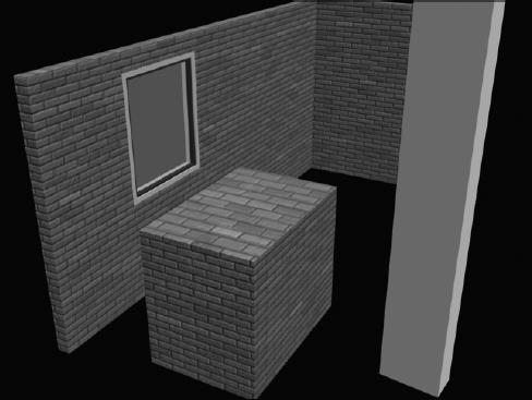
Select the BoxShort object.
Assign the Brick Wall material and then apply the UVW Map modifier to it. Choose the Box mapping method in the Parameters rollout. The Brick material appears on the box, showing all eight bricks on each side. The bricks are not the same size as those on the wall; this may be more apparent in a rendered view.

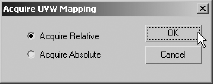
In the Alignment section of the Parameters rollout, click the Acquire button and then select the wall object.

In the Acquire UVW Mapping dialog box, make sure that Acquire Relative is selected and then click OK. Acquire Relative uses the same settings as the target object's gizmo, but it places the gizmo around the current object. Acquire Absolute uses the same settings as the target object's gizmo, and it co-locates the current gizmo with the target object's gizmo.
The box's UVW Map modifier's gizmo Size and Tiling values change to match those of the Wall object. Rendering the scene clearly shows the matched mapping between the two objects.
As with any other modifier in the modifier stack, the UVW Map modifier is applied to the result of the modifier or object below it in the stack. This must be considered when you are locating the modifier or the preferred result may occur. For example, Box mapping has a different result when it is applied to a box before it is bent than when it is applied after it is bent.
Select the BoxTall object and clone it to the right. Be sure to make the clone a copy, rather than an instance or a reference.
Apply the Checker1 material to both of the objects.
Select the original BoxTall and apply the UVW Map modifier. Choose the Box Mapping option.
Apply a Bend modifier to the box. Set the Angle to 90 and the Direction to −270. The checker pattern follows the curvature of the newly bent box.
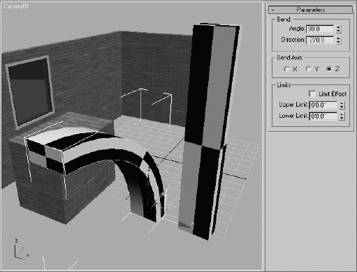
Select the second box and apply the Bend modifier with the same settings used in Step 4.
Apply the UVW Map modifier and select the Box mapping type. The gizmo in this case fits the extents of the bent box, and not the original box object, resulting in a different layout for the checker pattern.

As you can see, the location of the UVW Map modifier in the stack impacts the final appearance of the objects.
Creating materials for your objects is the next step after modeling them. Creating materials can give you a sense of accomplishment because it is essentially the last step in making the object look as you envisioned—aside from lighting and rendering, of course.
In this chapter, you learned the basics of materials, what kinds of materials are in 3ds Max, and how to create and edit them in the Material Editors. Then, you learned how choosing the right type of shader will make your surface look right, and then how to apply your knowledge to mapping a pool ball, reflections and all. Next, you learned a few more tricks of the Material Editor and all about the different kinds of maps available in 3ds Max. With that, you created a bump map and an opacity map.
There are several ways to create materials, from simple colors to complex mappings on distinct parameters. Finding the right combination of maps, Shader types, and Material types can make a world of difference in the look of your scenes. It's important to remember, like everything else in CG, texturing takes time, and gaining wisdom with your materials and maps will come with practice.