Building models in any 3D package comes down to creating and arranging vertices so that the appropriate polygonal shapes and organization of faces are sent to the renderer. The difference between a mesh shaped like a box and one shaped like a drum is how the vertices are organized. In recent releases of 3ds Max, the functionality and stability of the Polygon Modeling tools have been some of the most addressed areas. When using the Editable Poly toolset, or the Edit Poly modifier, the sub-objects of a mesh can be finely controlled to create almost any mesh object conceivable.
In 3ds Max, you can directly affect geometry objects and you can transform two-dimensional objects into three-dimensional geometry. Extruding, beveling, lofting, and lathing are just some of the ways to create geometry from splines. In this chapter, the Editable Poly toolset, the Lathe and Bevel modifiers, and the Loft compound object are covered while creating a low-polygon tank. We will also examine the ShapeMerge compound object, the Snapshot tool for creating copies of animated objects, and the Boolean Subtraction tool.
Topics in this chapter include:
Setting Up the Scene
The Editable Poly Tools
Lofting the Barrel
Lathing the Wheels
Using Snapshot to Create the Tracks
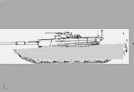
Using reference materials will help you efficiently create your 3D model and achieve a good likeness in your end result. The temptation to just "wing it" and start building the objects is often strong, especially when time is short. This temptation should always be suppressed in deference to a well thought-out approach to the task. Sketches, photographs, and drawings can all be used as resources for the modeling process; you can place them in a scene as backdrop images and model over them. Existing, similar models and even video clips or screen captures can be added to a scene as background images.
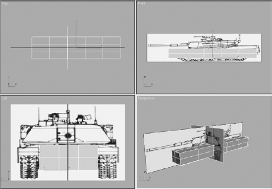
There are two common approaches for adding backdrop images for modeling: using the viewport's Background Image feature and placing the reference images on crossing plane objects or thin boxes. In this exercise, the crossing boxes technique is used as the starting point to build a low-polygon tank.
Open or reset 3ds Max.
In the Top viewport create a tall, wide box running along the X- axis.
In the Parameters rollout of the Command panel, set the Length to 0.1, Width to 400, and Height to 100.
With the box still selected, click the Move tool (


Note
Right-clicking on the spinner arrows to the right of an entry field immediately sets that field to its lowest possible, non-negative value.
The box will move to the origin.
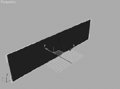
Create another box in the Top viewport. This one should run primarily along the Y- axis.
Set the Length to 150, Width to 0.1, and Height to 100.
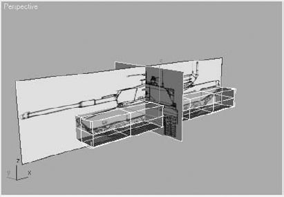
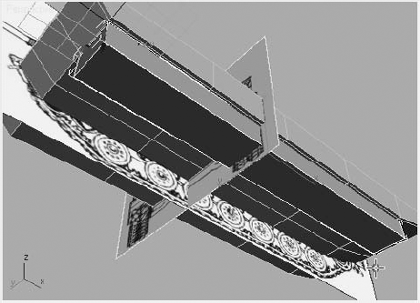
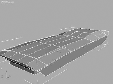
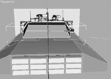
Move this box to the origin as well. The Perspective viewport should look similar to Figure 5.1.

Materials are covered in more depth in Chapter 7, "Materials and Mapping." For this exercise, you only need to know enough about the Material Editor to get the reference images to appear on the faces of the boxes. For now, the image maps must be in the same folder as the project file. Chapter 7 will show you how to assign paths where 3ds Max can look for the required support files.
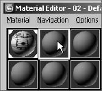
Click the Material Editor button (

The top-left sample sphere has a white border. This is the sample slot where you will make the first material. Your Material Editor might display fewer sample slots.
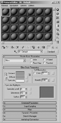
Expand the Maps rollout and click the Diffuse Color button currently labeled None.
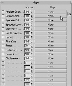
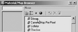
Double-click Bitmap at the top of the Material/Map Browser that opens.
In the Select Bitmap Image File dialog box that opens, navigate to the location of the Chapter 5 files from the companion CD and select the
Tank Front.jpgfile. A thumbnail image of the file will display in the Preview window. Click the Open button to add the first tank image to the material.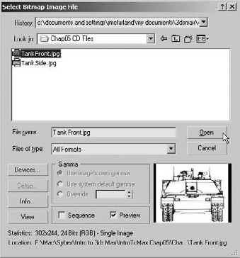
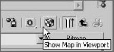
In the Material Editor's horizontal toolbar, click the Show Map in Viewport button. This causes the image map to be displayed in all viewports using the Smooth + Highlights display.
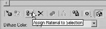
With the shorter box selected, click the Assign Material to Selection button in the Material Editor toolbar. The tank front image will display on the face of of the box.
In the sample slot area, select the sample slot to the right of the current slot. Its boundary turns white to indicate that it is the current material.
Repeat Steps 2 through 5, this time choosing the
Tank Side.jpgfile in the Select Bitmap Image File dialog box.Select the longer box, and then click the Assign Material to Selection button. Your Perspective viewport should look like Figure 5.2. If the images do not appear in the viewport, right-click on the viewport's title and choose Smooth + Highlights from the pop-up menu to change the viewport rendering mode.
Close the Material Editor.

The Editable Poly toolset available in 3ds Max 9 is very comprehensive and offers almost limitless potential for creating models. Using the proper tools and techniques, both low-polygon models, suitable for games or background objects, and smooth organic-looking objects are well within the capabilities of a skilled artist or modeler. In addition to moving and rotating the editable poly sub-objects, you will often use the following tools in polygonal modeling; you also had the chance to experiment with these tools in Chapter 4.
- Weld Vertices
Two adjacent polygons can share a vertex or each have its own collocated vertices. Welding combines any selected vertices, within the threshold distance apart, as a single vertex.
- Chamfer Edges or Vertices
This creates a new surface between two or more adjacent polygons. The angle of the new polygon is one-half the angle between the original polys. This creates a smoother transition between the adjoining surfaces.
- Bridge Borders
This builds polygons that span the distance between two borders on the same editable poly object.
- Cap Borders
This closes the selected border by creating new polygons.
- Extrude Polygons
Polygons are moved along the axis of their normal, creating additional vertices, edges, and polygons to connect them back to previously adjacent polys.
- Bevel Polygons
This is similar to Extrude, with the additional option to scale the relocated poly.
- Inset Polygons
This creates a new polygon by creating a new set of edges inset from the current polygon's perimeter.
- Hinge from Edge
This pivots the selected polygons about a user chosen edge. New polygons are created to span the gap.
- Attach
This attaches two or more editable polys to each other. The result is a single editable poly consisting of multiple, noncontiguous elements.
- Cut
This creates a new edge on the surface of a polygon.
- Connect Edges
This connects the selected edges by subdividing them the inserting edges at the newly created endpoints.
This chapter focuses on low-polygon modeling, and Chapter 6, "Organic Poly Modeling," addresses the tools and techniques used in organic modeling. In this exercise, the Vertex and Polygon sub-object levels are mainly used to form the tank's body and turret. In the later exercises in this chapter, lofting, the Lathe modifier, and the Snapshot tools are used to complete the tank.
To begin creating the body of the tank, follow these steps:
Continue with the previous exercise or open the
Tank1.maxfile from the companion CD.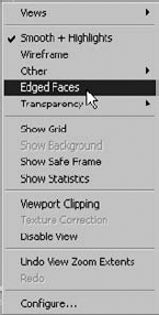
Right-click on the title of the Front viewport and change its Rendering mode to Smooth + Highlights. Right-click on it again and choose Edged Faces to display the scene objects' edges as well as their surfaces. Do the same to the Left viewport and turn on Edged Faces in the Perspective viewport; only the Top viewport should display the scene in wireframe.
To construct the tank, you need to build the tank's body by making a box, converting it to an editable poly and then editing its sub-objects.
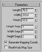
Create the box in the Top viewport to represent the volume of the tank's body between the treads. The Length, Width, and Height values should be approximately 76, 310, and 33, respectively.
Change the number of Length Segments to 3, Width Segments to 5, and Height Segments to 2. You want enough segmentation to account for the major changes in the body's structure, but not so much that manipulating the model becomes unwieldy.
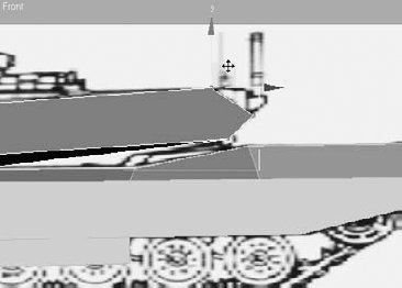
Move the box into the proper location, as shown in Figure 5.3. Make any necessary changes to the box's parameters so that it matches the volume of the tank body.
One situation that must be addressed is the fact that the box obscures the view of the background images. This is resolved by changing the box's properties so that it is displayed in See-Through mode.
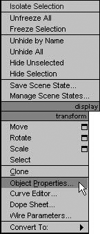
With the box selected, right-click in the viewport and choose Object Properties from the Quad menu.

In the Object Properties dialog box that opens, check the See-Through option in the Display Properties section and then click the OK button. The box becomes transparent in the viewports, and the edges remain visible, as shown in Figure 5.4. The keyboard shortcut for this feature is Alt+X.
Right-click again and choose Convert To → Convert to Editable Poly. The box is no longer a parametric object. It is now a collection of vertices, edges, and polygons, and the Command panel automatically switches to the Modify tab.
In the Command panel, change the name of the box to Tank Body.
EDITABLE POLY OR EDIT POLY MODIFIER?
In addition to the editable poly object, 3ds Max has the Edit Poly modifier. The Edit Poly modifier has the same toolset as the editable poly object, but it is applied through the Modifier Stack. The Edit Poly modifier has the advantage of allowing you to experiment with the sub-objects and their configurations. If the modifications are acceptable, the Modifier Stack is collapsed to an editable poly object. If the modifications are not acceptable, the modifier is deleted from the stack and the object reverts to its original configuration.
Converting an object directly to an editable poly or collapsing the Modifier Stack requires fewer system resources than maintaining the Modifier Stack intact.
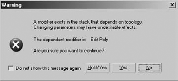
Making changes to the object at a level below the Edit Poly modifier usually adversely affects the model when they are transferred up the stack to the modifier. This is why a warning appears whenever an entry in the Modifier Stack below an Edit Poly modifier is selected.
Maximize the Front viewport and zoom in to the front half of the tank.
In the Selection rollout, click the Vertex button (

Drag a selection region around the vertices. Instead of clicking directly on a vertex, use a selection region because doing so will select all the vertices within the region and not only the vertex that is clicked on directly.
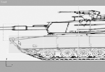
Move the selected vertices until they are at the top of the leading edge of the tank.

Select and move the two rows, one row at a time, to match the perimeter of the front of the tank.

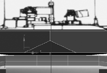
Continue forming the tank body by moving the vertices along the top of the tank. In Figure 5.5 the box's See-Through mode is turned off for clarity.
Move the middle, horizontal row of vertices to follow the line at the top of the skirt that covers the top of the track. Move the bottom row of vertices to follow the bottom of the skirt. The vertical edges, when possible, should match the edges of the skirt panels.

The basic shape of the body has been roughed in. The next step is to extend the body to encompass the track skirts. The polygons along the side of the model need to be extended and the sloped top surface need to be created.

Select the tank body object if necessary and click the Polygon button (

In the Perspective viewport, select all of the polygons on the right side of the tank.

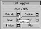
Several of the Editable Poly tools have two methods of implementing them: direct manipulation and a dialog box. Clicking on most tool buttons allows the user to click and drag on the selected sub-objects in order to manipulate them manually. Clicking the box-shaped Settings button (

Clicking the Apply button in a Settings dialog box applies the dialog's current values to the selected sub-objects and then previews the same parameters applied to the newly created and selected sub-objects. Clicking the OK button in a Settings dialog box applies the dialog's current values to the selected sub-objects and then exits the dialog box.
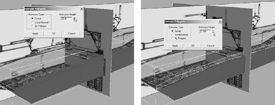
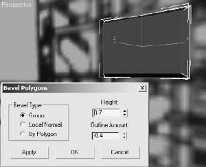
In the Edit Polygons rollout, click the Settings button next to the Extrude button to open the Extrude Polygons dialog box.
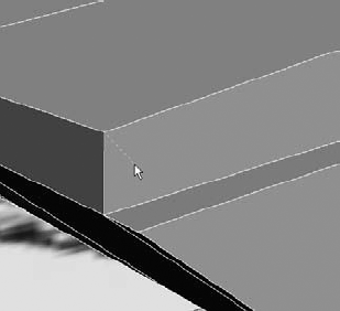
Extend the Extrusion Height value until the polygons reach the inside edge of the skirt shown in the tank's front reference image, and then click the OK button. (See graphic on bottom left.)
Deselect the top row of polygons, and then click the Extrude Settings button again. The selected polygons initially extrude to the same amount as the previous extrusion. Reduce the Extrusion Height value until the polygons extend to the outside of the skirt. (See graphic on bottom right.)
Render the scene, and you will see the shelf you just created that runs the length of the tank as shown in Figure 5.6. This is the top of the skirt. The small vertical surface above it needs to be collapsed to form the slope at the edges of the tank body's top surface. Vertical edges and their corresponding vertices must be added to the polygons to achieve an acceptable result.
Zoom in to the front-left edge of the model.

In the Edit Geometry rollout, click the Cut button.
The Cut tool places vertices on a model and creates the required edges to sub-divide the polygons. You need to be aware of the Cut tool's cursor appearance. A cursor that looks like a square over a cross indicates that the vertex will be placed on the surface of a polygon. A large cross indicates that it will be placed along an edge. A smaller cross uses an existing vertex as the end point for the new edges.
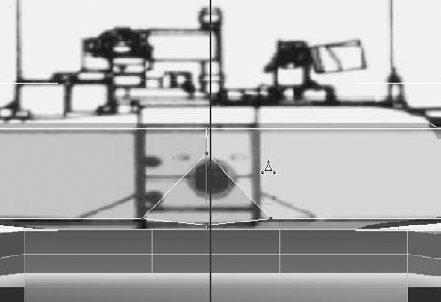
Place the cursor at a vertex on the top or bottom of the shelf where there is no corresponding vertex on the opposite edge, as shown in the left image in Figure 5.7.
Click and then move the cursor away from the vertex, and you will see the new edges forming as shown in the middle image in Figure 5.7.
Place the cursor over the edge in the middle of the shelf, as shown in the right image in Figure 5.7, then click to create the new vertex and edges.
Continue moving back along the tank's left side. Create vertical edges and corresponding vertices wherever the top surface of the tank changes shape, usually to accommodate the tapered edges of the vehicle where the top meets the side.

Switch back to the Vertex sub-object level and zoom into the front-left section of the tank again.
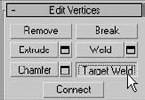
In the Edit Vertices rollout, click the Target Weld button. Using Target Weld, a selected vertex is moved and then welded to another specific vertex on the object.
Select a vertex along the top edge of the tank body. A rubber banding line connects the vertex to the cursor.
Move the cursor over the vertex directly below the currently selected vertex and click to complete the weld.
Continue welding the vertices of the vertical edges down the length of the tank.


The left side of the tank body is nearly finished. In this section, the bottom of the tank is opened—using Booleans—so that the tracks and the model can be made symmetrical.

Exit any sub-object mode if necessary.
Arc Rotate the Perspective viewport so that you can see the bottom of the tank.
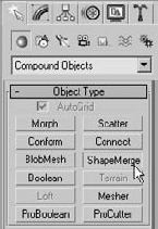
In the Command panel, click Geometry → Box and check the AutoGrid option at the top of the Object Type rollout.
Make sure the 3D Snap Toggle (

Click the vertex where the skirt meets the first flat poly at the bottom of the tank, and then click again on the vertex at the opposite corner of the last flat poly on the left at the rear of the tank. Drag and click to give the box some height. The box should project downward, from the bottom of the tank, equal to about half the tank body's height. Your scene should look similar to Figure 5.8.
Using the S shortcut key, turn off the 3D Snap Toggle. Then move and adjust the box to completely envelop the volume that will be the track well, as shown here.

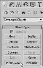
Select the tank body, and then choose Create → Geometry → Compound Objects → ProBoolean, as shown here.
Select Subtraction in the Parameters rollout, and then click the Start Picking button in the Pick Boolean rollout.

Click the box object in the viewport. The box will be deleted, taking the shared volume of the tank with it. Click the Start Picking button to turn it off.

The object is now a Boolean. Convert it back to an editable poly using the Quad menu; there is no need to maintain the data required to edit the object at the Boolean sub-object level.

Select and extrude and move the vertices of the polygons on the underside of the tank to match the front reference image.

Exit any sub-object mode.
The tank is a symmetrical object; however, rather than repeat the modeling process on the opposite side of the object, we will instead apply the Symmetry modifier. The Symmetry modifier maintains a symmetrical balance between both sides of an object.
With the tank body object selected, choose Symmetry from the Modifier List drop-down list.

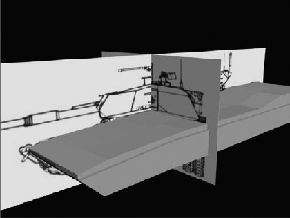
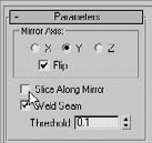
In the Symmetry modifier's Parameters rollout, choose the mirror axis that the object should mirror about. 3ds Max will choose the side of the object that is mirrored about the Mirror axis. If it chooses the wrong side, check the Flip option. Uncheck Slice Along Mirror; this will create a row of edges that aren't needed for this project. Your model should look similar to Figure 5.9. In the figure, the backdrop images have been hidden for clarity.
The last feature to add to the tank body is a series of exhaust vents at the rear of the vehicle. A simple box is created and then the Editable Poly tools are used to inset and isolate the polygons that are then hinged from one edge.
Continue from the previous exercise or open the
Tank4.maxfile from the companion CD.
Zoom in to the back of the tank.
Select Create → Geometry → Standard Primitives → Box, and check the AutoGrid option if necessary.
Create a box centered on the rear faces of the tank with a Length, Width, and Height of approximately 18, 70, and 7. Give the box 3 length segments, 4 width segments, and 1 height segment.

Convert the box into an editable poly.
Enter the Polygon sub-object level to select all twelve polygons on the rear surface of the box.

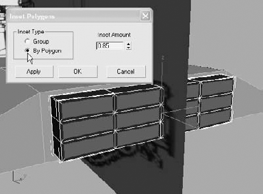
Click the Settings button next to the Inset button in the Edit Polygons rollout.

Set the Inset Amount to 0.85, choose By Polygon in the Inset Type area, and then click the OK button. By Polygon insets each polygon separately, rather than the entire selection as a single object.
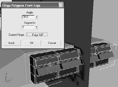
The exhaust vents need to pivot away from the tank as if they are hinged from the top edge. Select the top row of inset polygons and then click the Settings button next to the Hinge From Edge button in the Edit Polygons rollout.

Enter an Angle value of 30. Click the Pick Hinge button in the Hinge Polygons From Edge dialog box and then click any of the top edges of a selected polygon. All the selected polygons are pivoted about the same axis as the edge you select.

Click the Apply button. Apply pivots the selected polygons about the chosen hinge edge and leaves the dialog box open. However, the previous polygons are still selected and have been hinged again.
Select all of the polygons in the next row. The previous polygons revert to their hinged state before the Apply button was clicked while the newly selected polygons hinge at too great an angle. They also hinge from the same edge as the previous hinge operation.
Click the Current Hinge button, and then select an edge at the back of the middle selected row of polygons.
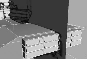
Repeat Steps 11 through 13 on the remaining row of polygons. Click the OK button to close the dialog box and then exit the Polygon sub-object level.
The exhaust vent is currently a separate object and should be just another part of the tank. The two objects are combined using the Attach feature of the Editable Poly tools. Attach adds the components of one object to another, leaving a single object with the combined features of both. Each object becomes an Element sub-object of the newly formed entity. Exit the sub-object selection level by clicking at the top of the Modifier Stack or using the 6 shortcut key.
Select the tank body object. In the Modifier Stack, click on the Editable Poly entry. Changes made to the object below the Symmetry modifier are then passed up to the modifier, maintaining the symmetrical balance of the model.
In the Edit Geometry rollout, click the Attach button.

Note
If more than one object must be attached, or if the objects to attach are difficult to select in the viewports, click the Settings button next to the Attach button. This opens the Attach List dialog box where the objects to attach are selected by name.
Click on the exhaust vent. The vent will become part of the tank body object.
Click the Attach button again to turn it off. Click Symmetry in the Modifier Stack to leave the Editable Poly level.
The turret must be able to rotate independently of the body, so it needs to be modeled as a separate object. We will start the modeling with a two-dimensional spline, convert it into an editable poly, and then use the Editable Poly tools to form the turret.

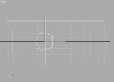
In the Command panel, select Create → Shapes → Splines → NGon and then drag in the Top viewport to create the shape.
Set the Radius value to 35 and the number of Sides to 5.
Rotate the ngon so that the point faces forward and the flat edge is parallel to the rear of the tank.
Move the shape up to the top of the tank body object and rename it to Tank Turret.
Convert the shape into an editable poly and then access the Polygon sub-object level.
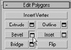
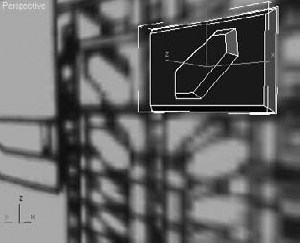
In the Edit Polygons rollout, click the Settings button next to the Bevel button. Bevel is similar to Extrude, but it has the additional capability to scale the selected polygon.
Set the Height to 2 and the Outline Amount to 21 to create the initial extrusion and bevel, and then click the Apply button.
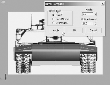
A second application of the same Bevel settings is applied to the new, currently selected polygon. Set the Height to 18 and the Outline Amount to −10 to create the next level of the turret's height. Click the OK button to apply the bevel and close the dialog box.

The rear of the turret needs to be extended and raised so that it does not impact the rear of the tank body when it rotates.
Select the polygon at the rear of the turret. Using the Move Transform gizmo, move the polygon toward the rear of the tank and raise it slightly using the background images as references. The edges of the adjacent polygons extend to maintain contact with the poly being moved.

Note
The current sub-object level, or the top level, of an editable poly can quickly be accessed from the tools 1 quadrant of the Quad menu or by using the number keys along the top row of the keyboard as shortcut keys (not the keys in the numeric keypad). The shortcuts are 1 = Vertex, 2 = Edge, 3 = Border, 4 = Polygon, 5 = Element, and 6 = Top Level.
Exit the Polygon sub-object level and use the Cut tool to add a horizontal edge dividing the rear polygon. Right-click to discontinue creating edges and then click the Cut button to turn it off.
Switch to the Vertex sub-object level. In the Front viewport, use a selection region to select each group of vertices at the rear of the turret and move them into place.
Switch to the Left viewport and then select the vertex at the leading point of the turret.
In the Edit Vertices rollout, click the Chamfer button.

Click and drag in the Left viewport to chamfer the selected vertex and create an additional polygon.
Use the Move tool to relocate the new vertices appropriately.
Exit the Vertex sub-object level.
The tank's crew needs to enter the tank from an access hatch on the top surface. This is also where the vehicle commander will sit to examine the battlefield. To create this feature, the ShapeMerge compound object is used to project the edges of a two-dimensional shape onto a three-dimensional surface, creating new edges and polygons on the 3D surface.
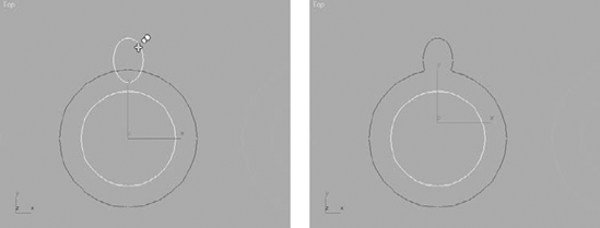
In the Top viewport, drag out a donut shape. Set the Radius 1 value to 10 and the radius 2 value to 15.

Move the donut in the Z-axis above the turret, so that the shape's edges will be projected onto the top of the turret.
Select the tank turret object, and then select Create → Geometry → Compound Objects → ShapeMerge.
In the Pick Operand rollout, click the Pick Shape button and select the donut in the viewport.
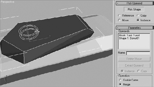
New edges appear on the top surface of the turret in the shape of the donut. Click the Pick Shape button to turn it off and then convert the turret back into an editable poly.
Select the donut shape and then delete it.
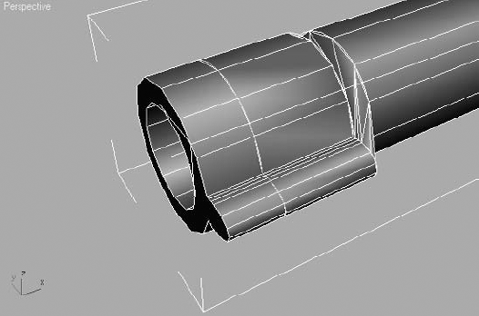
Select the outer ring of polygons and extrude them 1.5 units. Select the inner circle of polygons and extrude them 0.75 units. Exit the sub-object level when you are done. Save your work.

The main form of the low-poly tank model is now complete. The body has a sloped top and exhaust vent, and the turret has the crew's access hatch. In the next exercise, the Loft compound object is used to model the tank's barrel.
You can make a simple three-dimensional object by extruding a single two-dimensional shape perpendicular to the shape's orientation using the Extrude modifier. You can quickly complete building boxes, tubes, and even simple 3D text can quickly using the Extrude modifier. In contrast, the Loft compound object also builds 3D models by extruding one 2D spline along a second 2D spline. The first spline, called the shape object, becomes the cross section of the new 3D as it follows the second, path object. Tunnels, roller coaster tracks, fancy 3D text, and any object that needs to maintain a shape along a path are excellent opportunities to use the Loft compound object.
The Loft compound object has many features and only a few restrictions. The shape object can be complex, consisting of several noncontiguous splines and even nested splines. A new shape object can be selected at any point along the path, and the cross section automatically transitions from one shape to the next. Any 2D shape can be used as the shape object, but only shapes consisting of a single spline can be used as the path object.
To begin this exercise, several shapes are made to represent the different cross sections found along the length of the barrel.

Hide all of the objects in the scene.
In the Top viewport, create three circles, each with a radius of 2.75. Create three more circles, one with a radius of 3.75, one with 4.0, and one with 4.5.
From smallest to largest, rename the last three circles created to Barrel, Barrel Aim, and Barrel Evacuator.
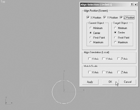
Align each of the smaller circles with one of the larger circles using the Align command. The X, Y, and Z Position check boxes should be checked, as well as the Center option for both the current and target objects.
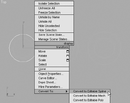
Select one of the larger circles, right-click and convert it to an editable spline from the Quad menu.
In the Geometry rollout, click the Attach button and select the corresponding inner circle. The inner circle will be made a spline component of a two-spline, noncontiguous shape. Click the Attach button to turn it off.
Repeat Steps 6 and 7 for the remaining two pairs of circles.
Create an ellipse object overlapping the outer circle of the barrel aim object and then attach this ellipse to the barrel aim object. Turn off the Attach tool when you are done.

Access the editable spline's Spline sub-object level, and then select the outer circle.

Similar to the Boolean operation used earlier in this chapter, spline Booleans can attach, subtract, or display the area of overlapping splines. With meshes, two separate objects are combined to form a single compound object. When using shapes, two separate spline sub-objects of the same shape are combined.
In the Geometry rollout, make sure the Union button is selected before clicking the Boolean button.
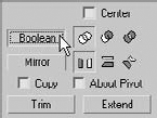
Click the ellipse-shaped spline as shown in the left image in Figure 5.10. The two splines are combined as a single spline as shown in the right image in Figure 5.10.
Exit the Spline sub-object level.
Unhide the box that shows the side view of the tank.
Click the Line tool in the Create → Shapes panel and turn on AutoGrid mode at the top of the Object Type rollout.
Click just inside the turret to place one end of the line.
Click again at the opposite side of the barrel and right-click to terminate the Line tool.

The shape or the path objects can be selected when the Loft tool is initiated. When the shape is selected, an instance of the path is moved to the shape; when the path is selected, an instance of the shape is moved to the path. The path is already located properly, so this object is used as the base for the barrel loft operation.
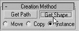
With the line already selected, select Create → Geometry → Compound Objects → Loft.

In the Creation Method rollout, click the Get Shape button.
Place the cursor over the Barrel object—it changes when it is over a valid shape object—and then click.
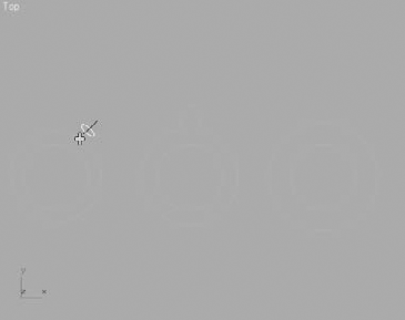
The shape is lofted along the path.

The Loft object is too dense for our needs; the barrel is not going to be bent or twisted, so the number of segments is higher than necessary. Expand the Skin Parameters rollout. Decrease the Shape Steps value to 2 and the Path Steps value to 0. Shape Steps defines the number of subdivisions between each vertex of the shape object, and Path Steps defines the number of subdivisions between each vertex of the path.
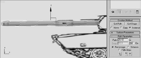
Turn on See-Through mode for the barrel. Look closely to the right end of the path in the Front viewport. You should see a yellow cross at the end of the line. The cross indicates the location along the path at which the shape object is placed. The Path field in the Path Parameters rollout sets the percentage or distance along the line where the cross is located. Any shape object placed at the current location of the cross extends to the end of the path unless another shape is placed farther along the path. Only one shape can be placed at any one location along the path.

Increase the Path value, in the Path Parameters rollout, until the yellow cross is even with the first, wide portion of the barrel.
Click the Get Shape button and then click the Barrel Evacuator shape. The new shape is applied to the path at the current location of the yellow cross, but the cross section transitions from the start of the barrel rather than the immediate transition shown in the reference image.
Change the Path value to 0.01 units lower than its current value. The Get Shape button should still be active; if it is not, click it and then click the Barrel shape again. There is a 0.01 transition distance between the cross section shapes, but this will not be noticeable.
Note
The Get Shape button stays active while the Path value is changed. You do not need to turn it on and off while changing the cross sections of a loft.
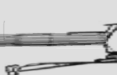
Increase the Path value to the end of the wider section of the barrel, as shown in the following image, and then click on the Barrel Evacuator object.
Increase the Path value a small amount, and click the Barrel shape again. The evacuator cross section ends after only a short span, and the barrel's standard diameter begins again.
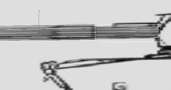
Increase the Path value until the yellow cross is near the end of the barrel, where the aiming point is located. Click the Barrel shape.
Increase the Path value a small amount, and then click the barrel aim shape. The Aim Point section of the barrel will appear, but it will be rotated improperly and there the barrel will be twisted as shown in Figure 5.11. These will be fixed shortly.
Increase the Path value until is approximately 98 percent along the path, and then click the barrel aim object again.
Increase the Path value a little more, and then click the Barrel shape again. The barrel will extend to the end of the path. Click the Get Shape button to turn it off.

Each spline has one vertex designated as the first vertex, which defines the direction of the spline. Open splines can have the first vertex at either end point, but not in the middle. Closed splines can have the first vertex at any vertex. Shapes that consist of several spline sub-objects have a first vertex for each spline.
Each cross section of the barrel cleanly transitions to the next, except for the transitions that include the barrel aim shape. To make the transitions, the designated first vertex is matched on each spline used as a shape object in the Loft. This is done so that when the circles are used exclusively, the first vertices will match well because all of the circles will have four vertices and each of their first vertices will be in the same relative location. When the Boolean operations were executed on the Barrel Aim object, the first vertex was relocated so that it no longer aligns with the other shapes.
The Shape and the Path components maintain a relationship with the Loft compound objects. This ensures that any changes made to either are reflected in the Loft. In this section, you will refine the spline shapes so that their vertices match up better.
Select the Barrel Aim shape, and then access the Vertex sub-object level. The first vertices are shown in yellow, and all others are shown in white.
Note
If you do not see the vertices, choose Customize → Preferences → Viewports and uncheck Show Vertices as Dots
Select the vertex at the top of the ellipse—it turns red to indicate that it is selected—and then click the Make First button in the Geometry rollout. Deselect any vertices, and the top vertex will turn yellow, indicating that it is the new first vertex.

Exit the Vertex sub-object level, and then select the Barrel object and access its Vertex sub-object level.
In addition to designating the top vertex as the first vertex, you will also add additional vertices to match the number found in the barrel aim object. Although this step isn't absolutely necessary when lofting, it adds to the result in this case.
Select the top vertex of the outer ring and make it the first vertex.
In the Geometry rollout, click the Refine button and click in two places—once on each side of the first vertex to correspond to the extra vertices created when the ellipse was added to the Barrel Aim outer circle. Turn off the Refine button and exit the Vertex sub-object mode.
Select the barrel evacuator object and make the top vertex of its outer ring the first vertex, similar to Steps 1 and 2.
Select the barrel loft object and rotate it 90 degrees counterclockwise, so the aim point is at the top of the barrel.
Rename the Loft01 object to Barrel Loft.
In the previous chapter, you used the Lathe modifier to create knobs for a chest of drawers. Here, you will use the Lathe modifier to create the wheels for the tank.
Continue with the previous exercise or open the
Tank7.maxfile from the companion CD. Unhide all hidden objects.In the Front viewport, create a box primitive with a Length and Width of 22 and a Height of 17. Increase the Length and Height Segments to 2. In the Left viewport, move the box over the track area of the background image. This is a temporary stand-in object that is the approximate size of the tank's lower wheels.
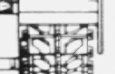
Click the Line tool in the Create panel, and turn on the AutoGrid option. Draw a line and then modify the vertices until the shape is similar to the line shown in Figure 5.12. The shape should be open on the bottom.
Delete the reference box.
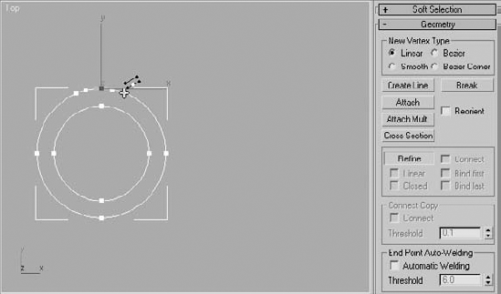
Select the spline and apply the Lathe modifier.
Choose X in the Direction section and Min in the Align section. These parameters cause the line to be revolved around its X- axis and place the pivot point near the bottom of the shape.
If necessary, check the Flip Normal option to expose the opposite side of the object's faces.
Expand the Lathe modifier in the Modifier Stack and choose the Axis sub-object level.
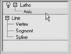
In the Left viewport, drag the Y-axis handle of the Move Transform gizmo downward to reposition the Lathe axis and expand the radius of the wheel. Be sure not to leave a noticeable hole at the center of the wheel.
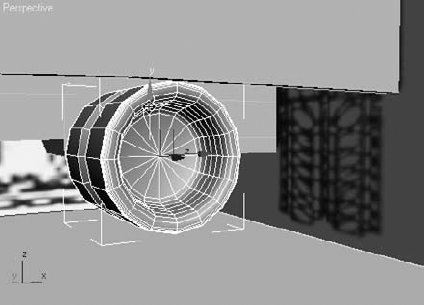
Exit the Axis sub-object level and rename the object to Wheel Lower.
Move the wheel to the front of the track. Make seven instanced clones of the wheel and place them over the existing wheels in the background image.

Note
The rear drive sprocket has a different design than the other wheels. Feel free to lathe a different shape to create that object.
Select all of the wheels and click the Mirror tool (

In the Mirror dialog box, choose Instance in the Clone Selection area. Decrease the Offset amount until the instanced wheels reach the tracks on the opposite side of the tank. Click the OK button to close the dialog box.


The tracks are a series of identical tread objects that are linked together to form a continuous belt. To quickly make all of the track treads, a single tread is made and then it is animated following the path that defines the path for all of the treads. The Snapshot tool is then used to create instanced clones of the tread at a user-specified increment of time. You don't need to know the proper time increment; the value can be "walked-in" by undoing and reapplying the Snapshot tool until the clones are made properly.
In this section you will create a single tank tread, using splines and the editable poly's Extrude function. The tread is then copied many times to form a continuous belt of treads.
Continue with the previous exercise or open the
Tank8.maxfile from the companion CD.
Hide all of the tank objects in the scene. Leave the background panels in place.
Zoom into one of the tracks in the Left viewport.
Use the Rectangle tool to make a rectangle that roughly follows the perimeter of one of the treads. Use the Line tool to draw a spline that follows the perimeter of the tread shoe. Make sure that the second spline is closed. You may need to move the Tank Front Reference image box back, behind the construction plane, to see your new objects.
Convert one of the objects into an editable poly and then attach the other object to it.
Rename this object Tread.
Select both polygons and bevel them with a Height of 0.7 and an Outline Amount of −0.4. Click OK to apply the bevel and close the dialog box.
Select the inner polygon and bevel it with the same settings as the previous bevel. Exit the Polygon sub-object level.
Mirror the tread to the other side of the track, choosing Copy in the Clone Selection area. Attach the new editable poly to the tread object.

In the Front viewport, draw a line that represents the path that the treads follow. Be sure to close the spline by placing the last vertex point over the first one and clicking the Yes button in the Close Spline dialog box that opens. Edit the path as necessary.

Rename the line to Tread Path.
The Tread must be animated following the path that you just drew. To do this, the Path Constraint is applied to the tread and the path is assigned as the object to follow.
Select the Tread object.
Click the Motion tab (

Expand the Assign Controller rollout and select the Position entry in the Controller window.
Click the Assign Controller button (


Select Path Constraint from the list and click the OK button. The dialog box will close, and the Path Constraint parameters will appear in the Motion panel.
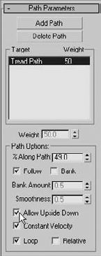
In the Path Parameters rollout, click the Add Path button and then select the tread path object in the viewport.

The path name will appear in the Target window. Check the Follow and Allow Upside Down options in the Path Options section. The Follow option causes the animated object to change its orientation to match the angle of the path segment at its current location. The Allow Upside Down option prevents the tread from flipping to maintain an upward orientation when the path returns the treads to the starting point.
Note
You can no longer move the Tread object using the Move Transform gizmo. The position of the tread is now constrained to the location of the path.
Move the path to the right until the tread is centered on the treads in the background image.
The tread is now animated so that it follows the path over the available length of animation. Drag the Time Slider, which runs along the bottom of the viewports, to the right until the tread is visible along the top section of the path. As you can see, the tread is oriented improperly; it is rotated vertically instead of horizontally.
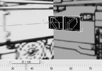
Select the tread and rotate it exactly 90 degrees to lay it flat along the path.

Drag the Time Slider back and forth and watch the tread object in the viewports; it maintains a constant orientation match to the path as it follows it from start to finish.
The Snapshot tool creates clones of selected objects at any designate interval of frames. This section uses Snapshot to create many identical treads.

The Snapshot tool is located on the Extras toolbar. Right-click on a blank area between any tools on a toolbar, and then click Extras on the context menu that appears.
With Tread selected, click and hold on the Array tool to display the flyout buttons. Release the mouse over the Snapshot tool to open the Snapshot dialog box.

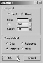
In the Snapshot section, choose Range and make sure the From and To values are 0 and 100, respectively. Set Copies to 80, and choose Instance in the Clone Method section. These settings mean that over the course of the 100 frame animation, instance clones of the tread are created every 1.25 frames for a total of 80 clones (100/80=1.25). Click OK.
The clones will be created and then the dialog box will close.

If the gap between the Tread clones is incorrect, Undo the Snapshot command and then initiate it again. The last settings used in the Snapshot dialog box are retained and just need to be tweaked.
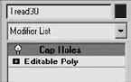
Apply a Cap Holes modifier to any of the Tread clones. Cap Holes creates a surface at the back of the tread objects. Without Cap Holes, the treads would not appear in a rendered scene as they pass under the tank wheels. This is because, with no surface on the under side of the treads, the normals of the visible faces would face the wrong directions and would not be rendered.
Hide the tread and tread path objects, as well as the background image boxes; they are no longer needed.
Unhide the tank body, tank turret, barrel loft, and wheel.
Copy the Tread clones, as instances, to the opposite side of the tank.
This completed low-poly tank project, with lights and a camera, can be opened as
Tank Complete.maxfrom the companion CD.

This chapter explored many of the tools used to create models with lower polygon counts. After setting up the scene with background images, some of the tools within the Editable Poly toolset were used extensively. The Extrude and Bevel tools were used to add or change the topology of polygons, and the Cut tool was used to add edges to surfaces. Booleans for mesh objects and splines were both briefly used to display just a bit of their capabilities, and the Symmetry modifier was used to maintain the model's symmetrical form. The Loft compound object displayed its abilities to extrude one shape along another's and change the cross section entirely at any point. Finally, the Snapshot tool was used to create many instanced copies of a single animated object.
In the next chapter, we will continue exploring the Editable Poly tools while creating a smooth, more organic model.