
8. Customizing Strokes
In This Chapter
Strokes can be much more than simple outlines for objects. Illustrator provides numerous tools for transforming them into visually rich elements.
Selecting a Stroke
An element’s stroke (visible outline) can be selected using a number of methods.
Select an object’s or the active stroke color using the toolbar
Do the following (Figure 8.1):
Double-click the stroke box on the toolbar to open the Color Picker.

FIGURE 8.1 Selecting an object’s stroke by double-clicking the stroke box in the toolbar to open the Color Picker
Tip
To learn more about the Color Picker, see Chapter 4.
Select an object’s stroke color or weight using panels
In the Control, Properties, or Appearance panel, do the following (Figure 8.2):
Click the stroke box to open the Swatches panel and select a different color.
Select or enter a new value in the Stroke Weight field.
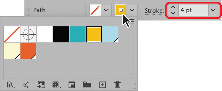
FIGURE 8.2 Accessing stroke color and weight options in the Control panel
Tip
To learn more about the Swatches panel, see Chapter 4.
Tip
Shift-click the field to open the Color panel instead of the Swatches panel.
Working with the Stroke Panel
You can open the Stroke panel (Figure 8.3) from other panels or the Window menu.

FIGURE 8.3 The Stroke panel
Open the Stroke panel independently
Do either of the following:
Choose Window > Stroke, and then select Show Options from the panel menu.
In the Essentials Classic workspace, click the Stroke panel thumbnail (Figure 8.4), and then select Show Options from the panel menu.
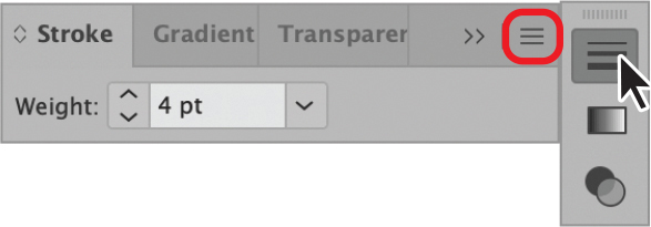
FIGURE 8.4 Accessing the Stroke panel from the thumbnail (panel menu highlighted)
Access the Stroke panel from another panel
In the Control, Properties, or Appearance panel, do the following (Figure 8.5):
Click the word Stroke to open the panel.

FIGURE 8.5 Accessing the Stroke panel from the Properties panel
Change the stroke weight
In Weight section of the Stroke panel, do any of the following:
Click up or down arrow buttons to incrementally increase or decrease the weight.
Enter a new amount in the value field.
Click the pulldown menu button and select a new weight (Figure 8.6).

FIGURE 8.6 Decreasing an object’s stroke weight using the menu
Change the stroke end cap
In the Cap section of the Stroke panel, do eany of the following:
Select the Butt Cap (default) option to align the end of the stroke with the path.
Select the Round Cap option to add an extended semicircular end (Figure 8.7).
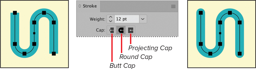
FIGURE 8.7 Object before and after applying a round end cap
Select the Projected Cap option to add an extended rectangular end.
Change the stroke corners
In the Corner section of the Stroke panel, do any of the following:
Select the Miter Join (default) option to assign pointed corners.
Select the Round Join option to assign elliptical corners (Figure 8.8).
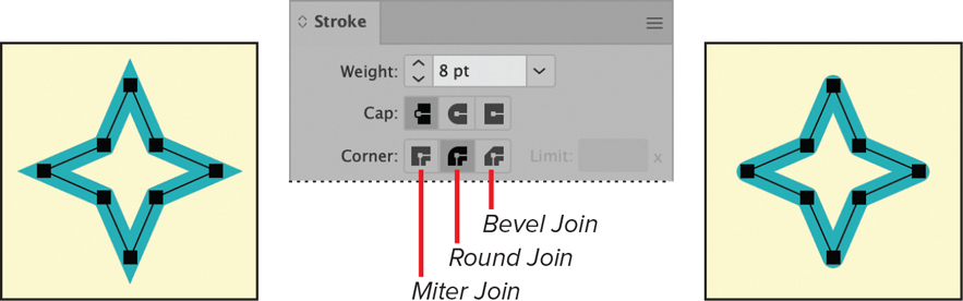
FIGURE 8.8 Object before and after applying a round join for the corners
Select the Bevel Join option to assign squared corners.
Tip
Some tight corners may require increasing the Corner Limit to enable them to appear.
Change the stroke alignment
In the Align Stroke section of the Stroke panel, do any of the following:
Select the Align to Center (default) option to position the stroke along the middle of the object’s outline.
Select the Align to Inside option to position the stroke within the object’s outline (Figure 8.9).
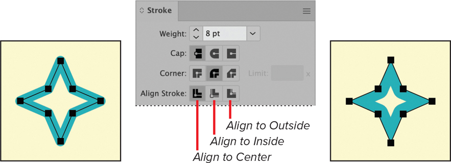
FIGURE 8.9 Object before and after applying an inside alignment to the stroke
Select the Align to Outside option to position the stroke along the outer edge of the object’s outline.
Tip
Inside and outside align options cannot be applied to open paths.
Assign a dashed line
In the Stroke panel, do the following (Figure 8.10):
Select Dashed Line.
Specify the Dash segment length.
Specify the Gap space length.

FIGURE 8.10 Dashed line properties applied to a path
Align Dashes to Corners and Path Ends
To position all the dashes at the corners of an object, maintaining visual consistency, do the following:
Select the Aligns Dashes to Corners and Path Ends, Adjusting Length to Fit option (Figure 8.12).
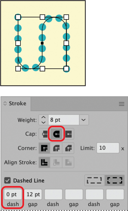
FIGURE 8.11 Dotted line properties applied to a path
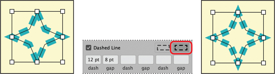
FIGURE 8.12 Object before and after applying dash alignment to the stroke
Assign a dotted line
In the Stroke panel, do the following (Figure 8.11):
Select Dashed Line.
Select the Round Cap option.
Enter 0 for the Dash segment length.
Specify the Gap space length as appropriate.
Assign arrowheads to a path
In the Stroke panel, do either of the following (Figure 8.13):
Select Arrowheads for the start and/or end points from the menus.
Specify the appropriate Scale for the arrowheads.

FIGURE 8.13 Path before and after applying and scaling arrowheads
Tip
Arrowhead size correlates with stroke width.
Reposition arrowheads
In the Stroke panel, do either of the following (Figure 8.14):
Click the Swap Start and End Arrowheads button to reverse the arrowheads.
In the Align section, select whether to extend the arrowhead beyond the end of the path or position them at the tip.
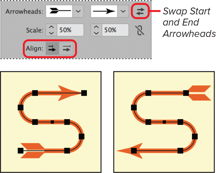
FIGURE 8.14 Arrowheads before and after swapping locations and extending beyond the path
Tip
Arrowheads also swap positions when you revert the path direction.
Applying Varied Stroke Widths
Variable strokes let you stylize stroke widths and mimic traditional pen and brush strokes.
Assign a variable-width profile
In the Stroke or Control panel, do the following (Figure 8.15):
Select a Profile from the menu.
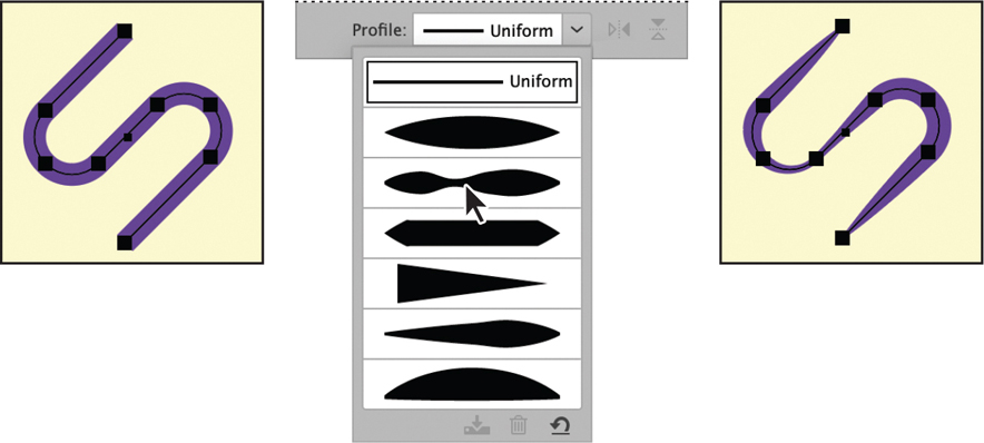
FIGURE 8.15 Path before and after applying a variable-width profile
Reverse an assigned variable-width profile
Do either the following (Figure 8.16):
Click the Flip Along button to vertically reverse the stroke.
Click the Flip Across button to horizontally reverse the stroke.
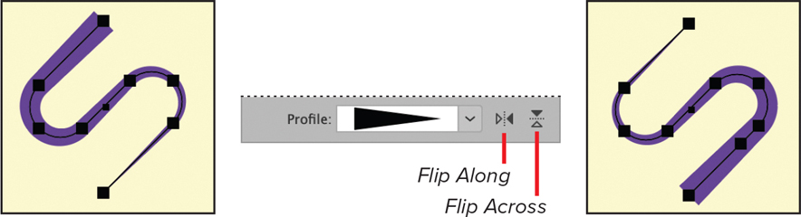
FIGURE 8.16 Path before and after clicking Flip Along button
Vary stroke width using the Width tool
The Width tool (Figure 8.17) lets you create customized variable-width strokes.

FIGURE 8.17 The Width tool in the Essentials Classic toolbar
With the Width tool active and the object you want to edit selected, do either of the following (Figure 8.18):
Click+drag outward to add a wider stroke point.
Click+drag inward to add a thinner stroke point.

FIGURE 8.18 Variably altering a path’s stroke using the Width tool
Modify a variable-width stroke
With the Width tool active and the object you want to edit selected, do the following:
Double-click the stroked path on an already existing width point or at the position you want to adjust.
Adjust the settings in the Width Point Edit dialog box, and then click OK.
Save a variable-width stroke
To add a customized variable-width stroke as a profile, do the following (Figure 8.19):
Select the variable-width stroke object.
In the Stroke or Control panel, click the Profile menu.
At the bottom of the menu, click the Add to Profiles button.
In the Variable Width Profile dialog box, enter a Profile Name, and then click OK.
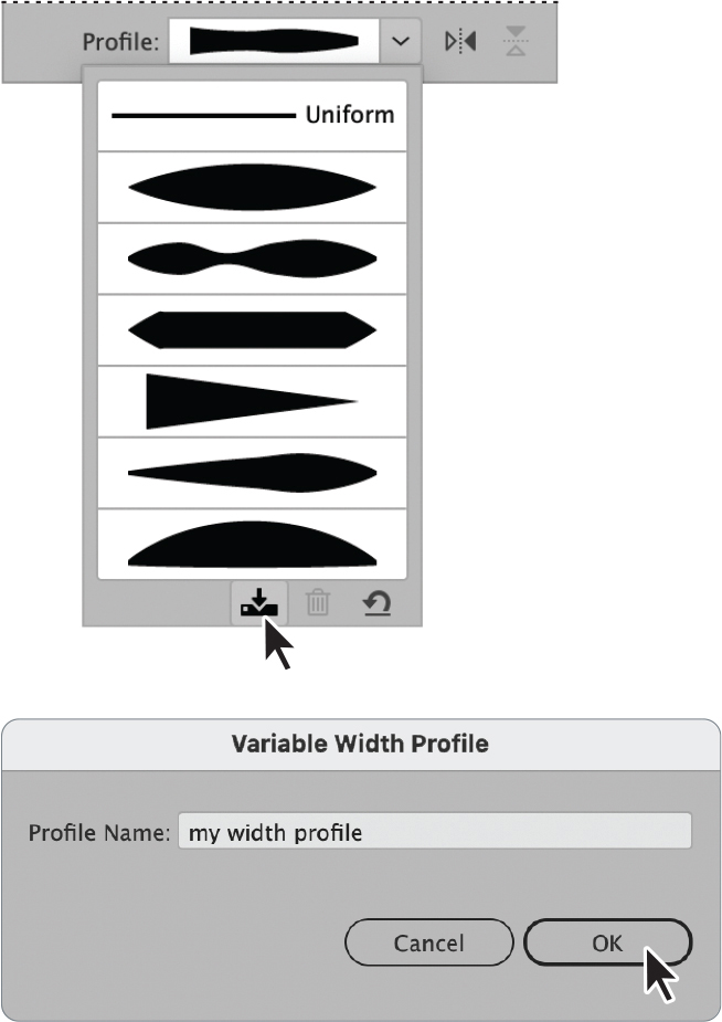
FIGURE 8.19 Adding a customized variable-width stroke to the profiles
Converting Stroked Paths to Objects
Outlining a stroke lets you quickly convert it into a shape, which allows for additional flexibility and control when editing.
Create a shape from an object’s stroke
Do the following (Figure 8.20):
Select the object with the stroke you want to convert.
Choose Object > Path > Outline Stroke.
(Optional) Choose Object > Ungroup to separate the new shape from the object’s fill element. Then deselect both elements and select the new shape individually.
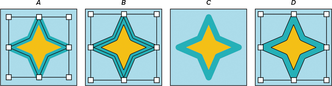
FIGURE 8.20
A. Object selected B. Stroke outlined C. Elements ungrouped and deselected D. New shape selected
Tip
Once you convert a stroke to a shape, it can be reverted only by choosing the Edit > Undo command, so make sure your artwork is in the its final form before converting the stroke.
![]() VIDEO 8.1
VIDEO 8.1
Working with strokes