Chapter 10
SD-WAN
Embracing the future of networking infrastructure needed to support the migration of applications to the cloud has driven Cisco to create faster, more reliable connectivity solutions. Additionally, the advent of the Internet of Things (IoT) has dictated that networks provide more performance as the number of consumers of applications (endpoints) expands. Traditionally this scaling out of endpoints would tax bandwidth and expose networks to new threats and vulnerabilities due the increase in the number of mobile users in the workforce.
In an effort to navigate this challenging landscape Cisco SD-WAN combines software-defined efficiency with a single pane of glass visibility across the WAN creating a secure extensible network that changes the way we look at networking today.
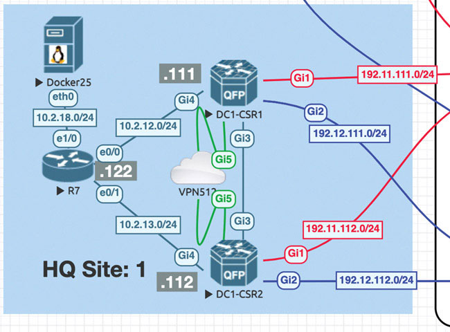
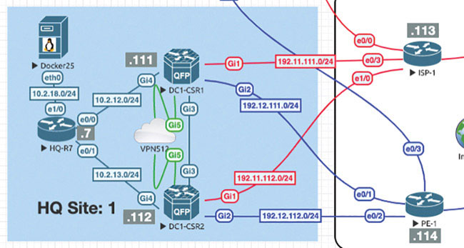
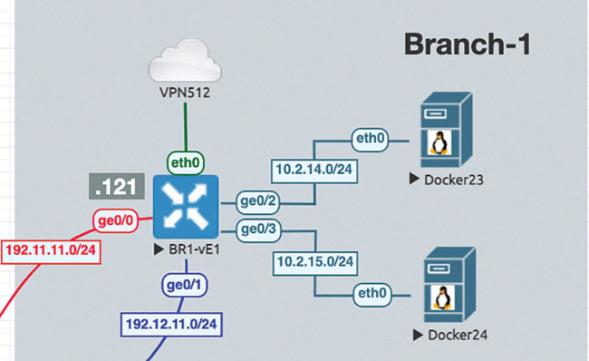
The following topology will be used for all the SD-WAN labs:
Lab 1: Onboarding WAN Edge Devices
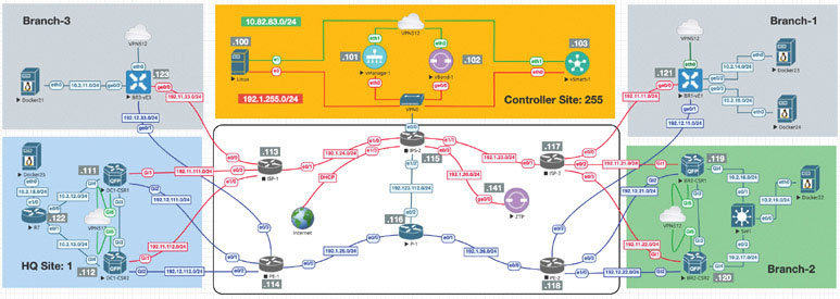
Navigate to Configuration > Devices > WAN Edge List > Upload WAN Edge List.
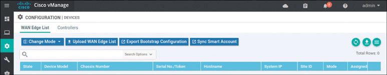
In the resulting popup window, click Browse. In the UI that appears, navigate to root > Downloads.
Select the file called serialfile-SDWAN-ENT.viptela.
Click Open.
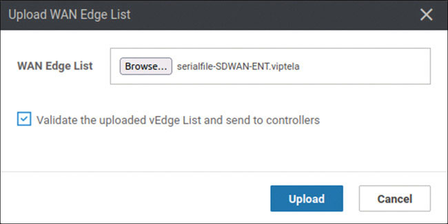
Check Validate the uploaded vEdge List and send to controllers and click Upload. The system asks one final time whether you actually want to install the list.
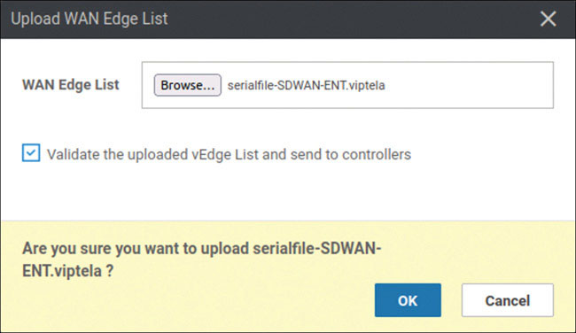
Click OK. The following message appears:
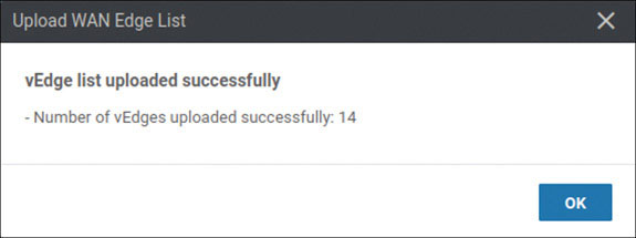
Click OK. You should see the following output as a result of this process:
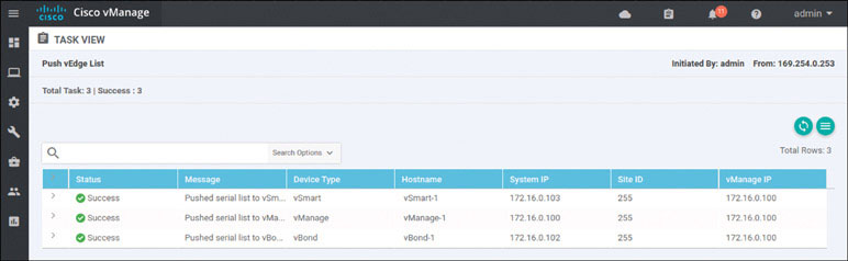
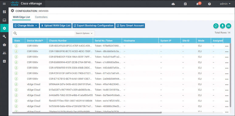
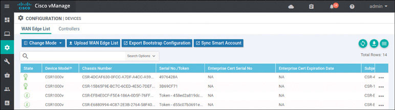
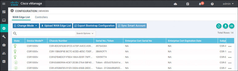
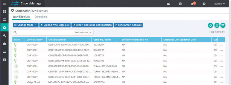
To verify the installation of the vEdge list, navigate to Configuration > Devices > WAN Edge List, where you should see a list of devices that have been whitelisted as a result of the steps you have already taken. These devices and only these devices can be added to your SEN fabric.
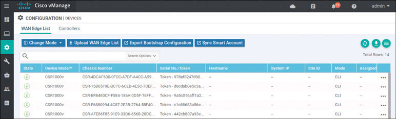
If you explore this list, you will find a combination of CSR1000v and Viptela cloud routers.
Now that you have installed the list of WAN edge devices, you need to focus on performing baseline configuration on all of the WAN edge devices for this lab. Begin by onboarding the devices in HQ Site 1:
The only devices that will be onboarded during this portion of the lab are DC1-CSR1 and DC1-CSR2. These devices are running IOS XE SD-WAN, and they can therefore be configured as part of the SD-WAN infrastructure. To accomplish this, you need to assign a baseline configuration to each of these devices via the CLI much as you would for controllers.
Next, you need to change the mode of the CSR from autonomous mode to controller mode:
Router>enable
Router# controller-mode enable
Enabling controller mode will erase the nvram filesystem, remove all
configuration files, and reload the box!
Ensure the BOOT variable points to a valid image
Continue? [confirm] enter
% Warning: Bootstrap config file needed for Day-0 boot is missing
Do you want to abort? (yes/[no]): enter
This forces the device to reload. Once the CSR has finished reloading, you need to configure the information it needs to operate as part of the SEN, including the following:
System IP address
Site ID
Organizational name
Identity of the vBond controller
You can focus on reachability and tunnel configuration after you provide the information required by the SD-WAN controllers. You can begin with DC1-CSR1, where you will access this CSR for the very first time. It is important to note that a CSR1000v device comes with a one-time login credential pair admin and admin. After you use these credentials, you need to configure a new username and password. Don’t panic if you see a message that uses a password 0 value. This just means the syntax you used is considered deprecated. This is how you access the CSR for the first time:
User Access Verification

Username: admin
Password: admin

Router>
*Feb 15 16:57:58.205: SDWAN INFO: WARNING: Please configure a new
username and password; one-time user admin is removed.
*Feb 15 16:57:58.227: %SEC_LOGIN-5-LOGIN_SUCCESS: Login Success [user:
admin] [Source: LOCAL] [localport: 0] at 16:57:58 UTC Sat Feb 15 2020
Router>
*Feb 15 16:58:06.320: %SYS-5-CONFIG_P: Configured programmatically by
process iosp_vty_100001_dmi_nesd from console as NETCONF on vty32131
*Feb 15 16:58:06.321: %DMI-5-CONFIG_I: R0/0: nesd: Configured from
NETCONF/RESTCONF by system, transaction-id 32
Now you can make some basic changes before you focus on SD-WAN. Set up the hostname and create a new set of credentials for the administrator account:
Router# config-transaction

admin connected from 127.0.0.1 using console on Router
Router(config)# hostname DC1-CSR1
Router(config)# username admin privilege 15 secret admin
Router(config)# commit
Commit complete.
DC1-CSR1(config)#
*Feb 15 17:01:16.043: %AAA-5-USER_RESET: User admin failed attempts
reset by NETCONF on vty32131
*Feb 15 17:01:16.043: % AAAA-4-CLI_DEPRECATED: WARNING: Command has
been added to the configuration using a type 5 password
. However, type 5 passwords which are considered weak are now depre-
cated.
*Feb 15 17:01:16.048: %SYS-5-CONFIG_P: Configured programmatically by
process iosp_vty_100001_dmi_nesd from console as NETCONF on vty32131
*Feb 15 17:01:16.049: %DMI-5-CONFIG_I: R0/0: nesd: Configured from
NETCONF/RESTCONF by admin, transaction-id 253
This example works, but the proper format would be to use the secret keyword rather than the password option. To illustrate that this example works, you can log out and then log back in before using the non-deprecated syntax:
DC1-CSR1(config)# exit
DC1-CSR1# exit
Now try to log in again:
User Access Verification

Username: admin
Password: admin

DC1-CSR1>
*Feb 15 17:06:14.247: %SEC_LOGIN-5-LOGIN_SUCCESS: Login Success [user:
admin] [Source: LOCAL] [localport: 0] at 17:06:14 UTC Sat Feb 15 2020
DC1-CSR1>enable
DC1-CSR1# config-transaction

admin connected from 127.0.0.1 using console on DC1-CSR1
DC1-CSR1(config)#
This works. Now you can configure the system information needed to add this cEdge device to the SEN fabric as part of the onboarding process:
DC1-CSR1# config-transaction

admin connected from 127.0.0.1 using console on DC1-CSR1
DC1-CSR1(config)# system
DC1-CSR1(config-system)# system-ip 10.1.1.111
DC1-CSR1(config-system)# site-id 1
DC1-CSR1(config-system)# organization-name micronicslab.com
DC1-CSR1(config-system)# vbond 192.1.255.102
DC1-CSR1(config-system)# commit
Commit complete.
DC1-CSR1(config-system)#
To verify that this configuration works, you can use the following command to look at part of the running configuration associated to the SD-WAN settings:
DC1-CSR1# show sdwan running-config
system
 system-ip             10.1.1.11
 site-id               101
 admin-tech-on-failure

 organization-name     micronicslab.com
 vbond 192.1.255.102
!
<output omitted>
Now that the basic SD-WAN configuration is done, you need to set up all the reachability information needed to attach DC1-CSR1 to the SD-WAN infrastructure. Here we focus on the information necessary to establish connectivity to the underlay. This will involve connectivity to both the MPLS and INET transports in the lab. You can use the EVE-NG topology drawing to find all the relevant information regarding IP addresses and gateways.
As shown below, configure the IP addresses on the interfaces that face the transport networks—specifically GigabitEthernet1 (MPLS) and GigabitEthernet2 (INET):
DC1-CSR1# config-transaction

admin connected from 127.0.0.1 using console on DC1-CSR1
DC1-CSR1(config)# interface GigabitEthernet1
DC1-CSR1(config-if)# no shutdown
DC1-CSR1(config-if)# ip address 192.11.111.111 255.255.255.0
DC1-CSR1(config-if)# exit
DC1-CSR1(config)# interface GigabitEthernet2
DC1-CSR1(config-if)# no shutdown
DC1-CSR1(config-if)# ip address 192.12.111.111 255.255.255.0
DC1-CSR1(config-if)# exit
DC1-CSR1(config)# ip route 0.0.0.0 0.0.0.0 192.11.111.113
DC1-CSR1(config)# ip route 0.0.0.0 0.0.0.0 192.12.111.114
DC1-CSR1(config)# ip name-server 8.8.8.8
DC1-CSR1(config)# commit
Commit complete.
DC1-CSR1(config)#
Now test reachability by trying to ping both gateways and the IP addresses of the controllers:
DC1-CSR1# ping 192.11.111.113 ← INET Gateway
Type escape sequence to abort.
Sending 5, 100-byte ICMP Echos to 192.11.111.113, timeout is 2 seconds:
!!!!!
Success rate is 100 percent (5/5), round-trip min/avg/max = 1/1/1 ms

DC1-CSR1# ping 192.12.111.114 ← MPLS Gateway
Type escape sequence to abort.
Sending 5, 100-byte ICMP Echos to 192.12.111.114, timeout is 2 seconds:
!!!!!
Success rate is 100 percent (5/5), round-trip min/avg/max = 1/1/2 ms


DC1-CSR1# ping 192.1.255.101 ← vManage-1
Type escape sequence to abort.
Sending 5, 100-byte ICMP Echos to 192.1.255.101, timeout is 2 seconds:
!!!!!
Success rate is 100 percent (5/5), round-trip min/avg/max = 1/1/1 ms

DC1-CSR1# ping 192.1.255.102 ← vBond-1
Type escape sequence to abort.
Sending 5, 100-byte ICMP Echos to 192.1.255.102, timeout is 2 seconds:
!!!!!
Success rate is 100 percent (5/5), round-trip min/avg/max = 20/28/31 ms

DC1-CSR1# ping 192.1.255.103 ← vSmart-1
Type escape sequence to abort.
Sending 5, 100-byte ICMP Echos to 192.1.255.103, timeout is 2 seconds:
!!!!!
Success rate is 100 percent (5/5), round-trip min/avg/max = 1/1/2 ms
DC1-CSR1#
You have all the reachability you need to proceed, but keep in mind that the configuration of SD-WAN requires the use of tunnels. In a Cisco device, you need an actual tunnel interface configured to allow the initiation and termination of DTLS tunnels. You will create discreet tunnel interfaces and associate those interfaces with the actual physical interfaces you use to attach to the transport networks. In SD-WAN, you will use ip unnumbered and a new (to you) tunnel mode that was specifically designed to support DTLS, with tunnel mode sdwan.
Before you do that, you need to copy the ROOTCA files that you created on vManage to the bootflash of DC1-CSR1. This will facilitate the onboarding of the CSR1000v and position all the files necessary to add the resource to the SD-WAN fabric. To do this, you need to access DC1-CSR1 and copy those files by using the following CLI commands:
DC1-CSR1# copy scp: bootflash:
Address or name of remote host []? 192.1.255.100
Source username [admin]? user
Source filename []? /home/user/Downloads/ROOTCA.pem
Destination filename [ROOTCA.pem]?
Password: Test123
 Sending file modes: C0644 1521 ROOTCA.pem
!
1521 bytes copied in 4.040 secs (376 bytes/sec)
DC1-CSR1#
Verify that the file was placed in the bootflash of DC1-CSR1:
DC1-CSR1# dir bootflash:ROOTCA.pem
Directory of bootflash:/ROOTCA.pem


40323   -rw-             1521  Aug 26 2020 15:17:10 +00:00  ROOTCA.pem

6286540800 bytes total (5007073280 bytes free)
DC1-CSR1#
Now you can build the tunnels on DC1-CSR1 that are needed to communicate with the controllers so that you can complete the onboarding process for this device:
DC1-CSR1# config-transaction

admin connected from 127.0.0.1 using console on DC1-CSR1
DC1-CSR1(config)# interface Tunnel 1
DC1-CSR1(config-if)# no shut
DC1-CSR1(config-if)# ip unnumbered GigabitEthernet1
DC1-CSR1(config-if)# tunnel source GigabitEthernet1
DC1-CSR1(config-if)# tunnel mode sdwan
DC1-CSR1(config-if)# exit
DC1-CSR1(config)# interface Tunnel 2
DC1-CSR1(config-if)# no shut
DC1-CSR1(config-if)# ip unnumbered GigabitEthernet2
DC1-CSR1(config-if)# tunnel source GigabitEthernet2
DC1-CSR1(config-if)# tunnel mode sdwan
DC1-CSR1(config-if)# exit
DC1-CSR1(config)#
Specify the configuration associated with these physical interfaces and logical tunnels under the sdwan configuration section of the IOS XE operating system:
DC1-CSR1(config)# sdwan
DC1-CSR1(config-sdwan)# interface GigabitEthernet1
DC1-CSR1(config-interface-GigabitEthernet1)# tunnel-interface
DC1-CSR1(config-tunnel-interface)# encapsulation ipsec
DC1-CSR1(config-tunnel-interface)# color biz-internet
DC1-CSR1(config-tunnel-interface)# exit
DC1-CSR1(config-interface-GigabitEthernet1)# exit
DC1-CSR1(config-sdwan)# interface GigabitEthernet2
DC1-CSR1(config-interface-GigabitEthernet2)# tunnel-interface
DC1-CSR1(config-tunnel-interface)# encapsulation ipsec
DC1-CSR1(config-tunnel-interface)# color MPLS
DC1-CSR1(config-tunnel-interface)# exit
DC1-CSR1(config-interface-GigabitEthernet2)# exit
DC1-CSR1(config-sdwan)# exit
DC1-CSR1(config)# commit

*Feb 15 18:04:01.181: %SYS-5-CONFIG_P: Configured programmatically by
process iosp_vty_100001_dmi_nesd from console as NETCONF on vty32131

*Feb 15 18:04:01.182: %DMI-5-CONFIG_I: R0/0: nesd: Configured from
NETCONF/RESTCONF by admin, transaction-id 381Commit complete.
*Feb 15 18:04:02.003: %LINEPROTO-5-UPDOWN: Line protocol on Interface
Tunnel1, changed state to up
*Feb 15 18:04:02.116: %LINEPROTO-5-UPDOWN: Line protocol on Interface
Tunnel2, changed state to up
DC1-CSR1(config)#
Next, you need the CSRs to join the SEN fabric in order to facilitate the turn up of the secure control plane. Each device needs to be able to authenticate to the vBond controller, and once that has taken place, each device can learn the identity of the vSmart controller in vManage. To do this, you need to use the ROOTCA.pem certificate you created to authenticate the controllers. You already copied that ROOTCA.pem certificate to DC1-CSR1. Now you need to use that certificate to facilitate the onboarding process.
Install the certificate as shown below:
DC1-CSR1# request platform software sdwan root-cert-chain install
bootflash:ROOTCA.pem
Uploading root-ca-cert-chain via VPN 0
Copying ... /bootflash/ROOTCA.pem via VPN 0
Updating the root certificate chain..
Successfully installed the root certificate chain
DC1-CSR1#
Based on how this lab is architected, you need to manually activate this specific cEdge router. You can accomplish this by using one of the chassis number/OTP pair values you uploaded using the serial file. You can arbitrarily select the lines to use, but it is a good idea to go in numerical order from the top. To find these whitelisted devices, you can look at the vManage dashboard and navigate to Configuration > Devices > WAN Edge List.
Note
Expand the Chassis Number and Serial No./Token columns so that you can see all the text in them. The information in these columns will be used to onboard the WAN edge devices.
To onboard CSR1 use the following syntax:
To onboard CSR1 use the following syntax: request platform software sdwan vedge_cloud activate chassis-number <UUID> token <OTP>
On DC1-CSR1, it looks like this:
DC1-CSR1# request platform software sdwan vedge_cloud activate
chassis-number CSR-20B67640-53EB-EBA1-58E2-84EDFF99D121 token
d51771230bad2d1b14192c2dd61e420f
*Feb 21 14:37:18.478: %DMI-5-AUTH_PASSED: R0/0: dmiauthd: User
'vmanage-admin' authenticated successfully from 10.1.255.101:36403 and
was authorized for netconf over ssh. External groups:
*Feb 21 14:37:26.795: %Cisco-SDWAN-DC1-CSR1-action_notifier-
6-INFO-1400002: R0/0: VCONFD_NOTIFIER: Notification: 2/21/2020
14:37:26 security-install-csr severity-level:minor host-name:default
system-ip:10.1.1.11
*Feb 21 14:37:36.437: %Cisco-SDWAN-DC1-CSR1-action_notifier-
6-INFO-1400002: R0/0: VCONFD_NOTIFIER: Notification: 2/21/2020
14:37:36 security-install-rcc severity-level:minor host-name:default
system-ip:10.1.1.11
*Feb 21 14:37:36.943: %DMI-5-AUTH_PASSED: R0/0: dmiauthd: User
'vmanage-admin' authenticated successfully from 10.1.255.101:36414 and
was authorized for netconf over ssh. External groups:
*Feb 21 14:37:51.347: %Cisco-SDWAN-DC1-CSR1-action_notifier-6-INFO-
1400002: R0/0: VCONFD_NOTIFIER: Notification: 2/21/2020 14:37:51
security-install-rcc severity-level:minor host-name:default
system-ip:10.1.1.11
*Feb 21 14:37:53.753: %DMI-5-AUTH_PASSED: R0/0: dmiauthd: User
'vmanage-admin' authenticated successfully from 10.1.255.101:36420 and
was authorized for netconf over ssh. External groups:
*Feb 21 14:37:59.186: %DMI-5-AUTH_PASSED: R0/0: dmiauthd: User
'vmanage-a
*Feb 21 14:39:11.830: %OSPF-6-DFT_OPT: Protocol timers for fast
convergence are Enabled.
*Feb 21 14:39:11.789: %Cisco-SDWAN-RP_0-OMPD-3-ERRO-400002: R0/0:
OMPD: vSmart peer 10.1.255.103 state changed to Init
*Feb 21 14:39:14.113: %Cisco-SDWAN-RP_0-OMPD-6-INFO-400002: R0/0:
OMPD: vSmart peer 10.1.255.103 state changed to Handshake
*Feb 21 14:39:14.123: %Cisco-SDWAN-RP_0-OMPD-5-NTCE-400002: R0/0:
OMPD: vSmart peer 10.1.255.103 state changed to Up
*Feb 21 14:39:14.124: %Cisco-SDWAN-RP_0-OMPD-6-INFO-400005: R0/0:
OMPD: Number of vSmarts
connected : 1
<output omitted for clarity>
You can clearly see that DTLS peering has taken place, based on this output, but to be on the safe side, you can verify it from the command line of DC1-CSR1 as shown below:
DC1-CSR1# show sdwan control local-properties
personality                       vedge
sp-organization-name              micronicslab.com
organization-name                 micronicslab.com
root-ca-chain-status              Installed

certificate-status                Installed
certificate-validity              Valid
certificate-not-valid-before      Feb 21 14:37:27 2020 GMT
certificate-not-valid-after       Feb 18 14:37:27 2030 GMT

enterprise-cert-status            Not-Applicable
enterprise-cert-validity          Not Applicable
enterprise-cert-not-valid-before  Not Applicable
enterprise-cert-not-valid-after   Not Applicable

dns-name                          192.1.255.102
site-id                           1
domain-id                         1
protocol                          dtls
tls-port                          0
system-ip                         10.1.1.11
chassis-num/unique-id             CSR-20B67640-53EB-EBA1-58E2-
                                  84EDFF99D121
serial-num                        1CEF1CA8
token                             Invalid
keygen-interval                   1:00:00:00
retry-interval                    0:00:00:18
no-activity-exp-interval          0:00:00:20
dns-cache-ttl                     0:00:02:00
port-hopped                       TRUE
time-since-last-port-hop          0:00:30:04
embargo-check                     success
number-vbond-peers                1
number-active-wan-interfaces      2


 NAT TYPE: E -- indicates End-point independent mapping
           A -- indicates Address-port dependent mapping
           N -- indicates Not learned
           Note: Requires minimum two vbonds to learn the NAT type


                         PUBLIC          PUBLIC PRIVATE         PRIVATE
              PRIVATE                              MAX   RESTRICT/           LAST
SPI TIME    NAT  VM
INTERFACE                IPv4            PORT   IPv4            IPv6
              PORT    VS/VM COLOR            STATE CNTRL CONTROL/     LR/LB  CONNECTION
REMAINING   TYPE CON

                                                         STUN
                 PRF
-----------------------------------------------------------------------------------------
GigabitEthernet1         172.1.1.11      12366  172.1.1.11      ::
              12366    1/0  mpls             up     2      no/yes/no   No/No  0:00:00:18
 0:11:51:53  N    5
GigabitEthernet2         172.2.2.11      12366  172.2.2.11      ::
              12366    1/1  biz-internet     up     2      no/yes/no   No/No  0:00:00:00
 0:11:51:38  N    5


DC1-CSR1#
You can see that the certificate is installed, the organization name is correct, and the connections to mpls and biz-internet are up. In addition, you can see that you have OMP peering going toward the vSmart device:
DC1-CSR1# show sdwan omp peers
R -> routes received
I -> routes installed
S -> routes sent

                       DOMAIN   OVERLAY   SITE

PEER           TYPE    ID       ID        ID    STATE  UPTIM   E      R/I/S
-----------------------------------------------------------------------------
10.1.255.103   vsmart  1        1         255   up     0:19:   59:22  0/0/0

DC1-CSR1#
You should now see something like this in the Configuration > Devices > WAN Edge List section of the vManage dashboard:
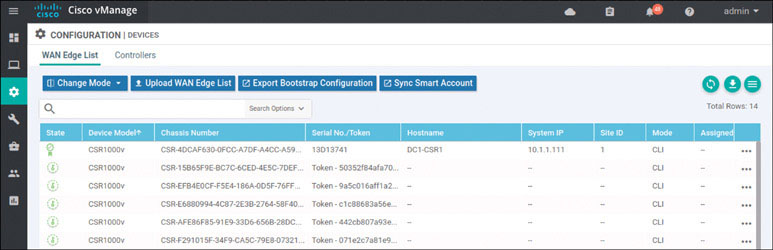
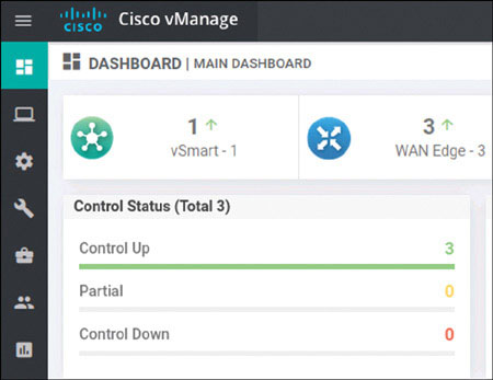
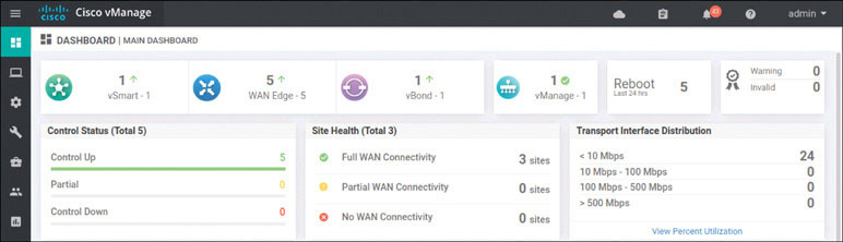
The interface shows the certificate symbol to the left of the line item, and you can see the hostname DC1-CSR1. This tells you that everything worked. To see if you can view the WAN devices on the main dashboard, go to Dashboard > Main Dashboard:
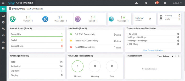
You can now see a number 1 with a green arrow pointing up next to the WAN edge field. This means you did everything correctly.
Rather than itemize every step involved in onboarding DC1-CSR2, this streamlines the process as the steps are identical to what you did on DC1-CSR1. Later, you will find that some sites have limited connectivity, and you will need to handle those situations. You will look at that more closely when you onboard devices in different sites.
You need to enable controller mode and then provide the baseline configuration for DC1-CSR2:
Router> enable
Router# controller-mode enable
Enabling controller mode will erase the nvram filesystem, remove all
configuration files, and reload the box!

Ensure the BOOT variable points to a valid image
Continue? [confirm] enter
% Warning: Bootstrap config file needed for Day-0 boot is missing
Do you want to abort? (yes/[no]): enter
The router reloads into controller mode. After that, you can finish the configuration as shown below:
User Access Verification

Username: admin
Password: admin

Default admin password needs to be changed.


Enter new password: admin
Confirm password: admin
Router> enable
Router# config-transaction
Router(config)# hostname DC1-CSR2
Router(config)# username admin privilege 15 secret admin
Router(config)# system
Router(config-system)# system-ip 10.1.1.112
Router(config-system)# site-id 1
Router(config-system)# organization-name micronicslab.com
Router(config-system)# vbond 192.1.255.102
Router(config-system)# interface GigabitEthernet1
Router(config-if)# no shutdown
Router(config-if)# ip address 192.11.112.112 255.255.255.0
Router(config-if)# exit
Router(config)# interface GigabitEthernet2
Router(config-if)# no shutdown
Router(config-if)# ip address 192.12.112.112 255.255.255.0
Router(config-if)# exit
Router(config)# ip route 0.0.0.0 0.0.0.0 192.11.112.113
Router(config)# ip route 0.0.0.0 0.0.0.0 192.22.101.114
Router(config)# ip name-server 8.8.8.8
Router(config)# commit
Move the ROOTCA.pem as shown below:
DC1-CSR2# copy scp: bootflash:
Address or name of remote host []? 192.1.255.100
Source username [DC1-CSR2]? user

Source filename []? /home/user/Downloads/ROOTCA.pem
Destination filename [ROOTCA.pem]?

Password: Test123
 Sending file modes: C0644 1521 ROOTCA.pem
!
1521 bytes copied in 2.826 secs (518 bytes/sec)
DC1-CSR2#
Configure the tunnel as shown below:
DC1-CSR2(config)# interface Tunnel 1
DC1-CSR2(config-if)# no shut
DC1-CSR2(config-if)# ip unnumbered GigabitEthernet1
DC1-CSR2(config-if)# tunnel source GigabitEthernet1
DC1-CSR2(config-if)# tunnel mode sdwan
DC1-CSR2(config-if)# exit
DC1-CSR2(config)# interface Tunnel 2
DC1-CSR2(config-if)# no shut
DC1-CSR2(config-if)# ip unnumbered GigabitEthernet2
DC1-CSR2(config-if)# tunnel source GigabitEthernet2
DC1-CSR2(config-if)# tunnel mode sdwan
DC1-CSR2(config-if)# exit
DC1-CSR2(config)# sdwan
DC1-CSR2(config-sdwan)# interface GigabitEthernet1
DC1-CSR2(config-interface-GigabitEthernet1)# tunnel-interface
DC1-CSR2(config-tunnel-interface)# encapsulation ipsec
DC1-CSR2(config-tunnel-interface)# color biz-internet
DC1-CSR2(config-tunnel-interface)# exit
DC1-CSR2(config-interface-GigabitEthernet1)# exit
DC1-CSR2(config-sdwan)# interface GigabitEthernet2
DC1-CSR2(config-interface-GigabitEthernet2)# tunnel-interface
DC1-CSR2(config-tunnel-interface)# encapsulation ipsec
DC1-CSR2(config-tunnel-interface)# color MPLS
DC1-CSR2(config-tunnel-interface)# exit
DC1-CSR2(config-interface-GigabitEthernet2)# exit
DC1-CSR2(config-sdwan)# commit
*Feb 21 19:04:16.027: %LINEPROTO-5-UPDOWN: Line protocol on Interface
Tunnel0, changed state to up
*Feb 21 19:04:16.068: %LINEPROTO-5-UPDOWN: Line protocol on Interface
Tunnel1, changed state to up
*Feb 21 19:04:16.087: %SYS-5-CONFIG_P: Configured programmatically by
process iosp_vty_100
001_dmi_nesd from console as NETCONF on vty32131

*Feb 21 19:04:16.088: %DMI-5-CONFIG_I: R0/0: nesd: Configured from
NETCONF/RESTCONF by admin, transaction-id 412
Commit complete.
DC1-CSR2(config-sdwan)# end
Install the root certificate as shown below:
DC1-CSR2# request platform software sdwan root-cert-chain install
bootflash:ROOTCA.pem
Uploading root-ca-cert-chain via VPN 0
Copying ... /bootflash/ROOTCA.pem via VPN 0
Updating the root certificate chain..
Successfully installed the root certificate chain
DC1-CSR2#
Now you need to manually register the CSR1000v using the next available CSR chassis and token combination in the vManage list of devices:
DC1-CSR2# request platform software sdwan vedge_cloud activate
chassis-number CSR-FF5D8B16-1C11-C3A8-5CFD-495CA090CD2C token
c07dda65c7a29728f4b3f083a28f72b7
DC1-CSR2#
<output omitted for clarity>
*Feb 21 19:15:04.608: %OSPF-6-DFT_OPT: Protocol timers for fast
convergence are Enabled.
*Feb 21 19:15:04.554: %Cisco-SDWAN-RP_0-OMPD-3-ERRO-400002: R0/0:
OMPD: vSmart peer 10.1.255.103 state changed to Init
*Feb 21 19:15:06.802: %Cisco-SDWAN-RP_0-OMPD-6-INFO-400002: R0/0:
OMPD: vSmart peer 10.1.255.103 state changed to Handshake
*Feb 21 19:15:06.804: %Cisco-SDWAN-RP_0-OMPD-5-NTCE-400002: R0/0:
OMPD: vSmart peer 10.1.255.103 state changed to Up
*Feb 21 19:15:06.804: %Cisco-SDWAN-RP_0-OMPD-6-INFO-400005: R0/0:
OMPD: Number of vSmarts connected : 1
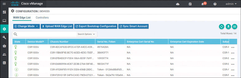
DC1-CSR2#After a short time, you should see the CSR registered with the SD-WAN fabric inside the user interface, as shown below:
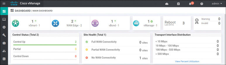
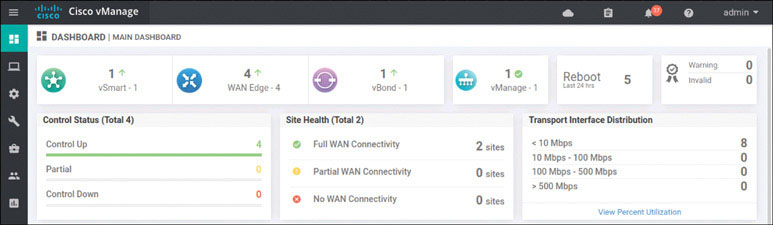
In addition, you should now see two WAN edge devices on the main dashboard, as shown below:
You have finished the setup for Site 1.
You can now bring up the other sites. The configurations are provided here for your reference. You need to onboard all of the WAN edge devices.
Site 2: CSR 1000v Onboarding
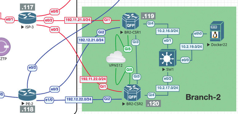
We will now repeat the onboarding operations on BR2-CSR1 by following this process:
Router>enable
Router# controller-mode enable
Enabling controller mode will erase the nvram filesystem, remove all configuration files, and reload the box!
Ensure the BOOT variable points to a valid image
Continue? [confirm] enter
% Warning: Bootstrap config file needed for Day-0 boot is missing

Do you want to abort? (yes/[no]): enter

<Device will reload!!!!!>

Router>en
Router# config-transaction
binos connected from 127.0.0.1 using console on Router
Router(config)# hostname BR2-CSR1
Router(config)# username admin privilege 15 secret admin
Router(config)# system
Router(config-system)# system-ip 10.1.1.21
Router(config-system)# site-id 2
Router(config-system)# organization-name micronicslab.com
Router(config-system)# vbond 192.1.255.102
Router(config-system)# interface GigabitEthernet1
Router(config-if)# no shutdown
Router(config-if)# ip address 192.11.21.119 255.255.255.0
Router(config-if)# exit
Router(config-system)# interface GigabitEthernet2
Router(config-if)# no shutdown
Router(config-if)# ip address 192.12.21.119 255.255.255.0
Router(config-if)# exit
Router(config)# ip route 0.0.0.0 0.0.0.0 192.11.21.117
Router(config)# ip route 0.0.0.0 0.0.0.0 192.12.21.118
Router(config)# ip name-server 8.8.8.8
Router(config)# interface Tunnel 1
Router(config-if)# no shut
Router(config-if)# ip unnumbered GigabitEthernet1
Router(config-if)# tunnel source GigabitEthernet1
Router(config-if)# tunnel mode sdwan
Router(config-if)# exit
Router(config)# interface Tunnel 2
Router(config-if)# no shut
Router(config-if)# ip unnumbered GigabitEthernet2
Router(config-if)# tunnel source GigabitEthernet2
Router(config-if)# tunnel mode sdwan
Router(config-if)# exit
Router(config)# sdwan
Router(config-sdwan)# interface GigabitEthernet1
Router(config-interface-GigabitEthernet1)# tunnel-interface
Router(config-tunnel-interface)# encapsulation ipsec
Router(config-tunnel-interface)# color biz-internet
Router(config-tunnel-interface)# allow-service all
Router(config-tunnel-interface)# exit
Router(config-interface-GigabitEthernet1)# exit

Router(config-sdwan)# interface GigabitEthernet2
Router(config-interface-GigabitEthernet2)# tunnel-interface
Router(config-tunnel-interface)# encapsulation ipsec
Router(config-tunnel-interface)# color mpls
Router(config-tunnel-interface)# allow-service all
Router(config-tunnel-interface)# exit
Router(config-interface-GigabitEthernet2)# exit
Router(config-sdwan)# commit
*Feb 21 19:39:34.118: %AAA-5-USER_RESET: User admin failed attempts
reset by NETCONF on vty32131
*Feb 21 19:39:34.118: %AAAA-4-CLI_DEPRECATED: WARNING: Command has
been added to the configuration using a type 5 password. However, type
5 passwords which are considered weak are now deprecated.
*Feb 21 19:39:34.481: %SYS-5-CONFIG_P: Configured programmatically by
process iosp_vty_100001_dmi_nesd from console as NETCONF on vty32131
*Feb 21 19:39:34.482: %DMI-5-CONFIG_I: R0/0: nesd: Configured from
NETCONF/RESTCONF by admin, transaction-id 278
*Feb 21 19:39:35.306: %LINEPROTO-5-UPDOWN: Line protocol on Interface
Tunnel1, changed state to up
*Feb 21 19:39:35.419: %LINEPROTO-5-UPDOWN: Line protocol on Interface
Tunnel2, changed state to up
*Feb 21 19:39:35.748: %Cisco-SDWAN-RP_0-OMPD-5-NTCE-400003: R0/0:
OMPD: Operational state changed to UP
Commit complete.
BR2-CSR1(config-sdwan)# end
Install the root certificate as shown below:
BR2-CSR1# copy scp: bootflash:
Address or name of remote host []? 192.1.255.100
Source username [admin]? user
Source filename []? /home/user/Downloads/ROOTCA.pem
Destination filename [ROOTCA.pem]?

Password: Test123
 Sending file modes: C0644 1521 ROOTCA.pem
!
1521 bytes copied in 2.627 secs (557 bytes/sec)

R31# request platform software sdwan root-cert-chain install
bootflash:ROOTCA.pem
Uploading root-ca-cert-chain via VPN 0
Copying ... /bootflash/ROOTCA.pem via VPN 0
Updating the root certificate chain..
Successfully installed the root certificate chain


BR2-CSR1# request platform software sdwan vedge_cloud activate chas-
sis-number CSR-D345642E-2A20-ADE1-90B9-AA97B37B25B5 token 5ad05603a12c
044c0cad7439168546de
*Feb 21 20:04:05.205: %Cisco-SDWAN-RP_0-OMPD-3-ERRO-400002: R0/0:
OMPD: vSmart peer 10.1.255.103 state changed to Init
*Feb 21 20:04:07.885: %CRYPTO-6-ISAKMP_ON_OFF: ISAKMP is ON
*Feb 21 20:04:07.415: %Cisco-SDWAN-RP_0-OMPD-6-INFO-400002: R0/0:
OMPD: vSmart peer 10.1.255.103 state changed to Handshake
*Feb 21 20:04:07.417: %Cisco-SDWAN-RP_0-OMPD-5-NTCE-400002: R0/0:
OMPD: vSmart peer 10.1.255.103 state changed to Up
*Feb 21 20:04:07.417: %Cisco-SDWAN-RP_0-OMPD-6-INFO-400005: R0/0:
OMPD: Number of vSmarts connected : 1
BR2-CSR1#
vManage shows that the addition has taken place:
In addition:
Onboard BR2-CSR2 as shown below:
Router>en
Router# controller-mode enable
Enabling controller mode will erase the nvram filesystem, remove all
configuration files, and reload the
box!
Ensure the BOOT variable points to a valid image
Continue? [confirm] enter
% Warning: Bootstrap config file needed for Day-0 boot is missing
Do you want to abort? (yes/[no]): enter

<Device will reload!!!!!>

Router(config)# hostname BR2-CSR2
Router(config)# username admin privilege 15 secret admin
Router(config)# system
Router(config-system)# system-ip 10.1.1.22
Router(config-system)# site-id 2
Router(config-system)# organization-name micronicslab.com
Router(config-system)# vbond 192.1.255.102
Router(config-system)# interface GigabitEthernet1
Router(config-if)# no shutdown
Router(config-if)# ip address 192.11.22.120 255.255.255.0
Router(config-if)# exit
Router(config-system)# interface GigabitEthernet2
Router(config-if)# no shutdown
Router(config-if)# ip address 192.12.22.120 255.255.255.0
Router(config-if)# exit
Router(config)# ip route 0.0.0.0 0.0.0.0 192.11.22.117
Router(config)# ip route 0.0.0.0 0.0.0.0 192.12.22.118
Router(config)# ip name-server 8.8.8.8
Router(config)# interface Tunnel 1
Router(config-if)# no shut
Router(config-if)# ip unnumbered GigabitEthernet1
Router(config-if)# tunnel source GigabitEthernet1
Router(config-if)# tunnel mode sdwan
Router(config-if)# exit
Router(config)# interface Tunnel 2
Router(config-if)# no shut
Router(config-if)# ip unnumbered GigabitEthernet2
Router(config-if)# tunnel source GigabitEthernet2
Router(config-if)# tunnel mode sdwan
Router(config-if)# exit
Router(config)# sdwan

Router(config-sdwan)# interface GigabitEthernet1
Router(config-interface-GigabitEthernet1)# tunnel-interface
Router(config-tunnel-interface)# encapsulation ipsec
Router(config-tunnel-interface)# color biz-internet
Router(config-tunnel-interface)# allow-service all
Router(config-tunnel-interface)# exit
Router(config-interface-GigabitEthernet1)# exit
Router(config-sdwan)# interface GigabitEthernet2
Router(config-interface-GigabitEthernet1)# tunnel-interface
Router(config-tunnel-interface)# encapsulation ipsec
Router(config-tunnel-interface)# color MPLS
Router(config-tunnel-interface)# allow-service all
Router(config-tunnel-interface)# exit
Router(config-interface-GigabitEthernet1)# exit
Router(config-sdwan)# commit
*Feb 21 19:39:34.118: %AAA-5-USER_RESET: User admin failed attempts
reset by NETCONF on vty32131
*Feb 21 19:39:34.118: %AAAA-4-CLI_DEPRECATED: WARNING: Command has
been added to the configuration using a type 5 password. However, type
5 passwords which are considered weak are now deprecated.
*Feb 21 19:39:34.481: %SYS-5-CONFIG_P: Configured programmatically by
process iosp_vty_100001_dmi_nesd from console as NETCONF on vty32131
*Feb 21 19:39:34.482: %DMI-5-CONFIG_I: R0/0: nesd: Configured from
NETCONF/RESTCONF by admin, transaction-id 278
*Feb 21 19:39:35.306: %LINEPROTO-5-UPDOWN: Line protocol on Interface
Tunnel1, changed state to up
*Feb 21 19:39:35.419: %LINEPROTO-5-UPDOWN: Line protocol on Interface
Tunnel2, changed state to up
*Feb 21 19:39:35.748: %Cisco-SDWAN-RP_0-OMPD-5-NTCE-400003: R0/0:
OMPD: Operational state changed to UP
Commit complete.
BR2-CSR2(config-sdwan)#
Install the root certificate as shown below:
BR2-CSR2# copy scp: bootflash:
Address or name of remote host []? 192.1.255.100
Source username [admin]? user
Source filename []? /home/user/Downloads/ROOTCA.pem
Destination filename [ROOTCA.pem]?

Password: Test123
 Sending file modes: C0644 1521 ROOTCA.pem
!
1521 bytes copied in 2.627 secs (557 bytes/sec)
BR2-CSR2#

BR2-CSR2# request platform software sdwan root-cert-chain install
bootflash:ROOTCA.pem
Uploading root-ca-cert-chain via VPN 0
Copying ... /bootflash/ROOTCA.pem via VPN 0
Updating the root certificate chain..
Successfully installed the root certificate chain

BR2-CSR2# request platform software sdwan vedge_cloud activate chas-
sis-number CSR-D345642E-2A20-ADE1-90B9-AA97B37B25B5 token 5ad05603a12c
044c0cad7439168546de
*Feb 21 20:04:05.205: %Cisco-SDWAN-RP_0-OMPD-3-ERRO-400002: R0/0:
OMPD: vSmart peer 10.1.255.103 state changed to Init
*Feb 21 20:04:07.885: %CRYPTO-6-ISAKMP_ON_OFF: ISAKMP is ON
*Feb 21 20:04:07.415: %Cisco-SDWAN-RP_0-OMPD-6-INFO-400002: R0/0:
OMPD: vSmart peer 10.1.255.103 state changed to Handshake
*Feb 21 20:04:07.417: %Cisco-SDWAN-RP_0-OMPD-5-NTCE-400002: R0/0:
OMPD: vSmart peer 10.1.255.103 state changed to Up
*Feb 21 20:04:07.417: %Cisco-SDWAN-RP_0-OMPD-6-INFO-400005: R0/0:
OMPD: Number of vSmarts connected : 1
BR2-CSR2#
You can see that the addition has taken place:
In addition:
Branch 1: vEdge Cloud Router Onboarding
We will prepare BR1-vE1 for onboarding using the following process:
vedge# config
Entering configuration mode terminal
vedge(config)# system
vedge(config-system)# host-name  BR1-vE1
vedge(config-system)# system-ip 10.1.1.11
vedge(config-system)# site-id 11
vedge(config-system)# organization-name micronicslab.com
vedge(config-system)# vbond 192.1.255.102
vedge(config-system)# exit
vedge(config)# vpn 0
vedge(config-vpn-0)# dns 8.8.8.8 primary
vedge(config-vpn-0)# ip route 0.0.0.0/0 192.11.11.117
vedge(config-vpn-0)# ip route 0.0.0.0/0 192.12.11.118
vedge(config-vpn-0)# interface ge0/0
vedge(config-interface-ge0/0)# ip address 192.11.11.121/24
vedge(config-interface-ge0/0)# no shut
vedge(config-interface-ge0/0)# tunnel-interface
vedge(config-tunnel-interface)# allow-service all
vedge(config-tunnel-interface)# color biz-internet
vedge(config-tunnel-interface)# encapsulation ipsec
vedge(config-tunnel-interface)# exit
vedge(config-interface-ge0/0)# exit
vedge(config-vpn-0)# interface ge0/1
vedge(config-interface-ge0/1)# no shut
vedge(config-interface-ge0/1)# ip address 192.12.1.121/24
vedge(config-interface-ge0/1)# tunnel-interface
vedge(config-tunnel-interface)# allow-service all
vedge(config-tunnel-interface)# color MPLS

vedge(config-tunnel-interface)# encapsulation ipsec
vedge(config-tunnel-interface)# commit and-quit
Commit complete.
Install the root certificate as shown below:
BR1-vE1# vshell
BR1-vE1:~$ scp [email protected]:/home/user/Downloads/ROOTCA.pem .
The authenticity of host '192.1.255.101 (192.1.255.101)' can't be
established.
ECDSA key fingerprint is SHA256:p9PbfLdHBQvHCIAkZMzFgSmgAI4zOLhf9i2rSp
Fw4UA.
Are you sure you want to continue connecting (yes/no)? yes
Warning: Permanently added '192.1.255.100' (ECDSA) to the list of
known hosts.
[email protected]'s password: Test123
ROOTCA.pem                                    100% 1521     1.5MB/s
00:00
BR1-vE1:~$ ls
ROOTCA.pem  archive_id_rsa.pub
BR1-vE1:~$ exit
BR1-vE1# request root-cert-chain install /home/admin/ROOTCA.pem
Uploading root-ca-cert-chain via VPN 0
Copying ... /home/admin/ROOTCA.pem via VPN 0
Updating the root certificate chain..
Successfully installed the root certificate chain
BR1-vE1#
Activate the vEdge device by using the chassis number and token for one of the vEdge cloud routers from the user interface:
BR1-vE1# request vedge-cloud activate chassis-number 32758328-6a9a-
2360-99ba-dc35d16db6aa token 4e2c986f5664ea27e76385698142127d
BR1-vE1#
Verify that the device has joined the SD-WAN fabric:
In addition:
Lab 2: Exploring Unicast Routing
To explore unicast concepts, you need to configure some routing in your topology. You can start with the HQ site, assigning interface IP addresses and configuring routing protocols and corresponding L3 virtual routing and forwarding (VRF) contexts.
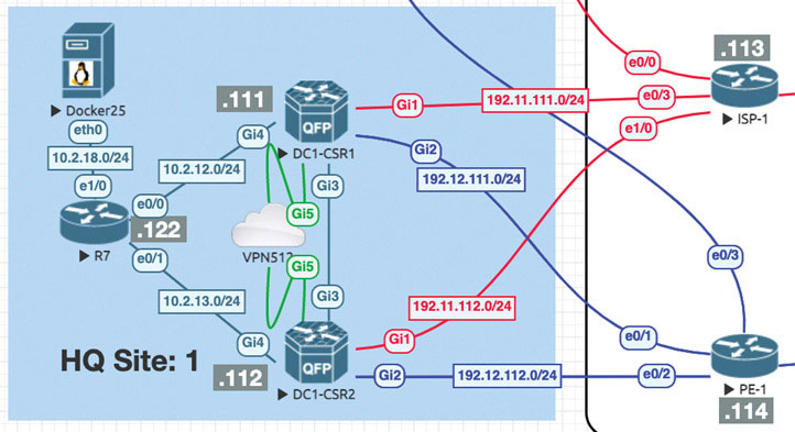
Let’s look at what happens when you create an interface that is part of the service-side, or LAN-side, configuration on a vEdge device. Here you will do this using GigabitEthernet4 on DC1-CSR1. This interface will be assigned an IP address. To see the process of advertising information to the vSmart device, you will see what transpires in the control plane as you configure this device.
First, look at the vSmart OMP routing table by entering this command:
vSmart-1# show omp routes vpn 0
vSmart-1#
Note that there are no OMP routes being learned by the vSmart device. As shown below, you can change that when you create a new VRF instance on DC1-CSR1 called VRF 100. You can then apply an IP address to the GigabitEthernet 4 interface of that same router and place it in VRF 100.
DC1-CSR1# config-transaction
DC1-CSR1(config)# vrf definition 100
DC1-CSR1(config-vrf)# address-family ipv4
DC1-CSR1(config-ipv4)# exit
DC1-CSR1(config-vrf)# exit
DC1-CSR1(config)# interface GigabitEthernet4
DC1-CSR1(config-if)# vrf forwarding 100
DC1-CSR1(config-if)# ip address 10.2.12.111 255.255.255.0
DC1-CSR1(config-if)# no shut
DC1-CSR1(config-if)# commit
Commit complete.
Now look at the vSmart device to see if anything has changed:
vSmart-1# show omp routes | tab
Code:
C   -> chosen
I   -> installed
Red -> redistributed
Rej -> rejected
L   -> looped
R   -> resolved
S   -> stale
Ext -> extranet
Inv -> invalid
Stg -> staged
U   -> TLOC unresolved

                                PATH                              ATTRIBUTE

VPN   PREFIX        FROM PEER   ID  LABEL STATUS  TYPE       TLOC IP   COLOR         ENCAP  PREFERENCE
------------------------------------------------------------------------------------------------------
100   10.2.12.0/24  10.1.1.111  66  1003   C,R    installed  10.1.1.111 mpls         ipsec  -
                    10.1.1.111  68  1003   C,R    installed  10.1.1.111 biz-internet ipsec  -

vSmart-1#
<output omitted>
You can see a new VPN entry called VPN100. Note that this is the same name you provided for your VRF instance in DC1-CSR1. You can explore this more closely by specifying the network 10.2.12.0/24 that you configured on GigibitEthernet3:
vSmart-1# show omp routes 10.2.12.0/24
Code:
C   -> chosen
I   -> installed
Red -> redistributed
Rej -> rejected
L   -> looped
R   -> resolved
S   -> stale
Ext -> extranet
Inv -> invalid
Stg -> staged
U   -> TLOC unresolved

                               PATH                          ATTRIBUTE
VPN  PREFIX        FROM PEER   ID  LABEL  STATUS  TYPE       TLOC IP     COLOR        ENCAP PREFERENCE
------------------------------------------------------------------------------------------------------
100  10.2.12.0/24  10.1.1.111  66  1003   C,R     installed  10.1.1.111  mpls         ipsec  -
                   10.1.1.111  68  1003   C,R     installed  10.1.1.111  biz-internet ipsec  -

vSmart-1#
Note that the network 10.2.12.0/24 (see the green highlight above) network is being advertised as being reachable from the interfaces on DC1-CSR1, facing the transport networks. Specifically, you can see that the network 172.101.1.0/24 can be reached via both mpls and biz-internet (see the yellow highlight above). You can also see that the device that advertised this information (the originator) has the system IP address 10.1.1.11 (see the blue highlight above).
Now you can add another device to the equation. To do so, you can create the same configuration on DC1-CSR2 that you just created, including creating VRF 100 and applying that VRF instance to interface GigabitEthernet4, along with assigning the IP address on that interface. All this is shown below:
DC1-CSR2# config-transaction

admin connected from 127.0.0.1 using console on DC1-CSR2
DC1-CSR2(config)# vrf definition 100
DC1-CSR2 (config-vrf)# address-family ipv4
DC1-CSR2 (config-ipv4)# exit
DC1-CSR2 (config-vrf)# exit

DC1-CSR2 (config)# interface GigabitEthernet4
DC1-CSR2 (config-if)# vrf forwarding 100
DC1-CSR2 (config-if)# ip address 10.2.13.112 255.255.255.0
DC1-CSR2 (config-if)# no shut
DC1-CSR2 (config-if)# commit
Commit complete.
Return to the vSmart device as shown below:
vSmart-1# show omp routes | tab
Code:
C   -> chosen
I   -> installed
Red -> redistributed
Rej -> rejected
L   -> looped
R   -> resolved
S   -> stale
Ext -> extranet
Inv -> invalid
Stg -> staged
U   -> TLOC unresolved

                               PATH               ATTRIBUTE

VPN  PREFIX        FROM PEER   ID  LABEL  STATUS  TYPE       TLOC IP    COLOR        ENCAP  PREFERENCE
------------------------------------------------------------------------------------------------------
100  10.2.12.0/24  10.1.1.111  66  1003   C,R     installed  10.1.1.111 mpls         ipsec  -
                   10.1.1.111  68  1003   C,R     installed  10.1.1.111 biz-internet ipsec  -
100  10.2.13.0/24  10.1.1.112  66  1003   C,R     installed  10.1.1.112 mpls         ipsec  -
                   10.1.1.112  68  1003   C,R     installed  10.1.1.112 biz-internet ipsec  -

vSmart-1#
Now you can see the network 10.2.13.0/24 advertised from system IP address 10.1.1.12 via mpls and biz-internet. What you really need to see here, though, is what the vSmart device did. Remember that the vSmart device acts like a route reflector: It advertises prefixes it learns for specific VPNs (or VRF instances, in the case of IOS XE SD-WAN devices) to other devices where those VPNs (or VRF instances) exist. You will explore this on the command line. But first I want to discuss my logic.
You know that DC1-CSR1 is advertising 10.2.12.0/24 to the vSmart device. You also know that DC1-CSR2 is advertising 10.2.13.0/24 to the vSmart device. Also, based on what we discussed earlier, you also know that the vSmart device should “reflect” those routes to DC1-CSR1 and DC1-CSR2 because they both are configured in the VPN/VRF 100. You can verify this as shown below:
DC1-CSR2# show ip route vrf 100

Routing Table: 100
Codes: L - local, C - connected, S - static, R - RIP, M - mobile,
B - BGP
       D - EIGRP, EX - EIGRP external, O - OSPF, IA - OSPF inter area
       N1 - OSPF NSSA external type 1, N2 - OSPF NSSA external type 2
       E1 - OSPF external type 1, E2 - OSPF external type 2, m - OMP
       n - NAT, Ni - NAT inside, No - NAT outside, Nd - NAT DIA
       i - IS-IS, su - IS-IS summary, L1 - IS-IS level-1, L2 - IS-IS
level-2
       ia - IS-IS inter area, * - candidate default, U - per-user
static route
       H - NHRP, G - NHRP registered, g - NHRP registration summary
       o - ODR, P - periodic downloaded static route, l - LISP
       a - application route
       + - replicated route, % - next hop override, p - overrides from
PfR
       & - replicated local route overrides by connected

Gateway of last resort is not set

      10.0.0.0/8 is variably subnetted, 2 subnets, 2 masks
C        10.2.13.0/24 is directly connected, GigabitEthernet4
L        10.2.13.112/32 is directly connected, GigabitEthernet4
DC1-CSR2#
Seeing this might make you question what we discussed earlier. It seems as though you would see some mention of 10.2.12.0/24 on DC1-CSR2 if the vSmart device is acting as a route reflector. But that is not the case. To more clearly understand this process, you need to consider how this information is exchanged. Remember that you use OMP as the protocol in the overlay. Given this, you might be able to see the prefixes you are looking for if you look in the OMP routing table. To reduce the amount of output you get, you can look specifically for 10.2.12.0/24 on DC1-CSR2:
DC1-CSR2# show sdwan omp routes 10.2.12.0/24
Code:
C   -> chosen
I   -> installed

Red -> redistributed
Rej -> rejected
L   -> looped
R   -> resolved
S   -> stale
Ext -> extranet
Inv -> invalid
Stg -> staged
IA  -> On-demand inactive
U   -> TLOC unresolved
                                 PATH            ATTRIBUTE

VPN  PREFIX        FROM PEER     ID LABEL STATUS TYPE       TLOC IP     COLOR        ENCAP PREFERENCE
------------------------------------------------------------------------------------------------------
100  10.2.12.0/24  10.1.255.103  1  1003  Inv,U  installed  10.1.1.111  mpls         ipsec  -

                   10.1.255.103  2  1003  Inv,U  installed  10.1.1.111  biz-internet ipsec  -


DC1-CSR2#
This is fantastic! You can see route 10.2.12.0/24, and you can see that it was originated on 10.1.1.11 (DC1-CSR1), and it can be reached via both mpls and biz-internet. Also, you learned it from 10.1.255.103 (vSmart-1). All this happened without you needing to do anything. But can you reach this prefix from DC1-CSR2? Remember that you have to specify the VRF (100), as shown below:
DC1-CSR2# ping vrf 100 10.2.12.111
Type escape sequence to abort.
Sending 5, 100-byte ICMP Echos to 172.101.1.1, timeout is 2 seconds:
.....
Success rate is 0 percent (0/5)
DC1-CSR2#
You can see here that you do not have reachability. But this makes sense. Remember that the routing table for the VRF instance must have the prefix in it, or it must have a default route of some kind to afford reachability. You can determine whether the table includes the prefix as shown below:
DC1-CSR2# show ip route vrf 100

Routing Table: 100
Codes: L - local, C - connected, S - static, R - RIP, M - mobile,
B - BGP
       D - EIGRP, EX - EIGRP external, O - OSPF, IA - OSPF inter area
       N1 - OSPF NSSA external type 1, N2 - OSPF NSSA external type 2

       E1 - OSPF external type 1, E2 - OSPF external type 2, m - OMP
       n - NAT, Ni - NAT inside, No - NAT outside, Nd - NAT DIA
       i - IS-IS, su - IS-IS summary, L1 - IS-IS level-1, L2 - IS-IS
level-2
       ia - IS-IS inter area, * - candidate default, U - per-user
static route
       H - NHRP, G - NHRP registered, g - NHRP registration summary
       o - ODR, P - periodic downloaded static route, l - LISP
       a - application route
       + - replicated route, % - next hop override, p - overrides from
PfR
       & - replicated local route overrides by connected

Gateway of last resort is not set

      10.0.0.0/8 is variably subnetted, 2 subnets, 2 masks
C        10.2.13.0/24 is directly connected, GigabitEthernet4
L        10.2.13.112/32 is directly connected, GigabitEthernet4
DC1-CSR2#
You can see that there is no prefix, so there is no reachability.
You have routes in OMP, and you want to get those routes to appear in VRF 100. The issue here is that both DC1-CSR1 and DC1-CSR2 belong to Site-1. To prevent loops, you can’t place the routes learned from DC1-CSR1 into the routing table of VRF 100. It stands to reason that there should be no circumstance where you would prefer the overlay network to reach a prefix that originated within the site where your devices are located. To drive this point home, you can go to DC1-CSR1 and temporarily change the site ID to 100. This should facilitate making the prefix appear on DC1-CSR2, as shown below:
DC1-CSR1# config-transaction

admin connected from 127.0.0.1 using console on DC1-CSR1
DC1-CSR1(config)# system
DC1-CSR1(config-system)# site-id 100
DC1-CSR1(config-system)# commit
Commit complete.
Now that you have done this, you can see if the prefix for 10.2.12.0/24 appears in the routing table of DC1-CSR2, as shown below:
DC1-CSR2# show ip route vrf 100

Routing Table: 100
Codes: L - local, C - connected, S - static, R - RIP, M - mobile,
B - BGP
       D - EIGRP, EX - EIGRP external, O - OSPF, IA - OSPF inter area
       N1 - OSPF NSSA external type 1, N2 - OSPF NSSA external type 2

       E1 - OSPF external type 1, E2 - OSPF external type 2, m - OMP
       n - NAT, Ni - NAT inside, No - NAT outside, Nd - NAT DIA
       i - IS-IS, su - IS-IS summary, L1 - IS-IS level-1, L2 - IS-IS
level-2
       ia - IS-IS inter area, * - candidate default, U - per-user
static route
       H - NHRP, G - NHRP registered, g - NHRP registration summary
       o - ODR, P - periodic downloaded static route, l - LISP
       a - application route
       + - replicated route, % - next hop override, p - overrides from
PfR
       & - replicated local route overrides by connected

Gateway of last resort is not set

      10.0.0.0/8 is variably subnetted, 3 subnets, 2 masks
m     10.2.12.0/24 [251/0] via 10.1.1.111, 00:00:08, Sdwan-system-intf
C     10.2.13.0/24 is directly connected, GigabitEthernet4
L     10.2.13.112/32 is directly connected, GigabitEthernet4
DC1-CSR2#
Now you have some progress. You can see a route for 10.2.12.0/24 learned via 10.1.1.111 (DC1-CSR1) with the routing code m, which corresponds to OMP. Now you can see if the prefix is reachable, as shown below:
DC1-CSR2# ping vrf 100 10.2.12.111
Type escape sequence to abort.
Sending 5, 100-byte ICMP Echos to 10.2.12.111, timeout is 2 seconds:
!!!!!
Success rate is 100 percent (5/5), round-trip min/avg/max = 1/1/2 ms
DC1-CSR2#
This is the output you want, but you don’t want to leave the configuration like this. In fact, you should take this one step further and build the OSPF infrastructure in Site-1. To do so, you need to apply IP addresses and configure OSPF DC1-CSR1, DC1-CSR2, and R7.
You can put DC1-CSR1 back into site ID 101. In addition, you can use the process ID 100 for the OSPF configuration to match the VRF/VPN number 100:
DC1-CSR1# config-transaction

admin connected from 127.0.0.1 using console on DC1-CSR1
DC1-CSR1(config)# system
DC1-CSR1(config-system)# site-id 1
DC1-CSR1(config-system)# exit
DC1-CSR1(config)# router ospf 100 vrf 100

DC1-CSR1(config-router)# router-id 0.0.0.111
DC1-CSR1(config-router)# commit
Commit complete.
Now you can configure HQ-R7 as shown below:
Router# conf t
Enter configuration commands, one per line.  End with CNTL/Z.
Router(config)# hostname HQ-R7
HQ-R7(config)# no ip domain lookup
HQ-R7(config)# line con 0
HQ-R7(config-line)# logg synchronous
HQ-R7(config-line)# no exec-timeout
HQ-R7(config-line)# exit
HQ-R7(config)# interface e0/0
HQ-R7(config-if)# ip address 10.2.12.7 255.255.255.0
HQ-R7(config-if)# no shut
HQ-R7(config-if)# int e0/1
HQ-R7(config-if)# ip address 10.2.13.7 255.255.255.0
HQ-R7(config-if)# no shut
HQ-R7(config-if)# int lo 0
HQ-R7(config-if)# ip address 183.1.7.7 255.255.255.255
HQ-R7(config-if)# exit
HQ-R7(config)# router ospf 100
HQ-R7(config-router)# router-id 0.0.0.7
HQ-R7(config-router)# network 10.2.0.0 0.0.255.255 area 0
HQ-R7(config-router)# network 183.1.100.100 0.0.0.0 area 0
You would expect to see an adjacency form here if the configuration is set up correctly. You can verify that all three interfaces are configured to operate in OSPF Area 0 and that 10.2.12.111 (DC1-CSR1) is reachable:
HQ-R7# show ip ospf int bri
Interface    PID   Area            IP Address/Mask    Cost  State Nbr
s F/C
Lo0          100   0               183.1.7.7/24       1     LOOP  0/0
Et1/0        100   0               10.2.18.7/24       10    DR    0/0
Et0/1        100   0               10.2.13.7/24       10    DR    0/0
Et0/0        100   0               10.2.12.7/24       10    DR    0/0
HQ-R7# ping 10.2.12.111
Type escape sequence to abort.
Sending 5, 100-byte ICMP Echos to 10.2.12.111, timeout is 2 seconds:
.!!!!
Success rate is 80 percent (4/5), round-trip min/avg/max = 1/1/1 ms
HQ-R7#
You have reachability, but obviously nothing is set up on DC1-CSR1, so you enter the command shown below:
DC1-CSR1# show ip ospf int brief
DC1-CSR1#
You can see that this is not right. You need the router to have the interface GigabitEthernet3 to run OSPF and form the missing adjacency. To fix this, you can simply use the interface command as shown below:
DC1-CSR1(config)# interface GigabitEthernet 4
DC1-CSR1(config-if)# ip ospf 100 area 0
DC1-CSR1(config-if)# commit
Commit complete.
*Mar 28 15:12:54.688: %OSPF-5-ADJCHG: Process 100, Nbr 0.0.0.7 on
GigabitEthernet4 from LOADING to FULL, Loading Done
Finally, you can move to DC1-CSR2 and enter the commands shown below:
DC1-CSR2# config-transaction

admin connected from 127.0.0.1 using console on DC1-CSR2
DC1-CSR2(config)# router ospf 100 vrf 100
DC1-CSR2(config-router)# exit
DC1-CSR2(config)# interface GigabitEthernet 4
DC1-CSR2(config-if)# ip ospf 100 area 0
DC1-CSR2(config-if)# commit
Commit complete.
DC1-CSR2(config-if)#
*Aug 27 18:57:31.173: %OSPF-5-ADJCHG: Process 100, Nbr 0.0.0.7 on
GigabitEthernet4 from LOADING to FULL
Now you have built an OSPF environment in Site-1. All devices are again in the same site, and therefore you will not see any prefixes learned from OMP, as shown below:
DC1-CSR2# show ip route vrf 100 omp
Routing Table: 100
Codes: L - local, C - connected, S - static, R - RIP, M - mobile,
B - BGP
D - EIGRP, EX - EIGRP external, O - OSPF, IA - OSPF inter area
N1 - OSPF NSSA external type 1, N2 - OSPF NSSA external type 2
E1 - OSPF external type 1, E2 - OSPF external type 2, m - OMP
n - NAT, Ni - NAT inside, No - NAT outside, Nd - NAT DIA
i - IS-IS, su - IS-IS summary, L1 - IS-IS level-1, L2 - IS-IS
level-2
ia - IS-IS inter area, * - candidate default, U - per-user
static route
H - NHRP, G - NHRP registered, g - NHRP registration summary
o - ODR, P - periodic downloaded static route, l - LISP
a - application route
+ - replicated route, % - next hop override, p - overrides from
PfR
Gateway of last resort is not set
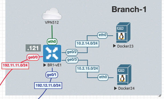
DC1-CSR2#To remedy this situation, you can go to Branch-1 and add BR1-vE1 to VPN 100. You can just create a physical interface for this lab, as shown below:
BR1-vE1# config
Entering configuration mode terminal
BR1-vE1(config)# vpn 100
BR1-vE1(config-vpn-100)# interface ge0/2
BR1-vE1(config-interface-ge0/2)# ip address 10.2.14.121/24
BR1-vE1(config-interface-ge0/2)# no shut
BR1-vE1(config-interface-ge0/2)# commit and-quit
Commit complete.
BR1-vE1#
If you did this correctly, you should expect BR1-vE1 to learn something from the vSmart device regarding the VPN 100 routes in Site-1. To see if this is the case, you can investigate what’s happening on BR1-vE1, as shown below:
BR1-vE1# show ip route vpn 100
Codes Proto-sub-type:
  IA -> ospf-intra-area, IE -> ospf-inter-area,
  E1 -> ospf-external1, E2 -> ospf-external2,
  N1 -> ospf-nssa-external1, N2 -> ospf-nssa-external2,
  e -> bgp-external, i -> bgp-internal
Codes Status flags:
  F -> fib, S -> selected, I -> inactive,
  B -> blackhole, R -> recursive

                               PROTOCOL  NEXTHOP  NEXTHOP  NEXTHOP
VPN    PREFIX        PROTOCOL  SUB TYPE  IF NAME  ADDR     VPN   TLOC IP     COLOR        ENCAP STATUS
------------------------------------------------------------------------------------------------------
100    10.2.12.0/24  omp       -         -        -        -     10.1.1.111  mpls         ipsec  F,S
100    10.2.12.0/24  omp       -         -        -        -     10.1.1.111  biz-internet ipsec  F,S
100    10.2.13.0/24  omp       -         -        -        -     10.1.1.112  mpls         ipsec  F,S
100    10.2.13.0/24  omp       -         -        -        -     10.1.1.112  biz-internet ipsec  F,S
100    10.2.14.0/24  connected -         ge0/2    -        -     -           -            -      F,S

100    10.2.18.0/24  omp       -         -        -        -     10.1.1.111  mpls         ipsec  F,S
100    10.2.18.0/24  omp       -         -        -        -     10.1.1.111  biz-internet ipsec  F,S
100    10.2.18.0/24  omp       -         -        -        -     10.1.1.112  mpls         ipsec  F,S
100    10.2.18.0/24  omp       -         -        -        -     10.1.1.112  biz-internet ipsec  F,S
100    183.1.7.7/32  omp       -         -        -        -     10.1.1.111  mpls         ipsec  F,S
100    183.1.7.7/32  omp       -         -        -        -     10.1.1.111  biz-internet ipsec  F,S
100    183.1.7.7/32  omp       -         -        -        -     10.1.1.112  mpls         ipsec  F,S
100    183.1.7.7/32  omp       -         -        -        -     10.1.1.112  biz-internet ipsec  F,S

BR1-vE1#
Here, you are learning about the prefixes in Site-1 that are directly attached to the routers DC1-CSR1 and DC1-CSR2—and you are learning a lot of other things. Specifically, you can see the Loopback0 interface of HQ-R7 (183.1.7.7) and the physical links on DC1-CSR1 and DC1-CSR2. You can test reachability as shown below:
BR1-vE1# ping 10.2.12.111 vpn 100 count 5
Ping in VPN 100
PING 10.2.12.111 (10.2.12.111) 56(84) bytes of data.
64 bytes from 10.2.12.111: icmp_seq=1 ttl=255 time=0.971 ms
64 bytes from 10.2.12.111: icmp_seq=2 ttl=255 time=1.29 ms
64 bytes from 10.2.12.111: icmp_seq=3 ttl=255 time=1.09 ms
64 bytes from 10.2.12.111: icmp_seq=4 ttl=255 time=0.997 ms
64 bytes from 10.2.12.111: icmp_seq=5 ttl=255 time=1.29 ms

--- 10.2.12.111 ping statistics ---
5 packets transmitted, 5 received, 0% packet loss, time 4003ms
rtt min/avg/max/mdev = 0.971/1.131/1.299/0.143 ms
BR1-vE1# ping 10.2.13.112 vpn 100 count 5
Ping in VPN 100
PING 10.2.13.112 (10.2.13.112) 56(84) bytes of data.
64 bytes from 10.2.13.112: icmp_seq=1 ttl=255 time=1.17 ms
64 bytes from 10.2.13.112: icmp_seq=2 ttl=255 time=3.28 ms
64 bytes from 10.2.13.112: icmp_seq=3 ttl=255 time=1.12 ms
64 bytes from 10.2.13.112: icmp_seq=4 ttl=255 time=1.02 ms
64 bytes from 10.2.13.112: icmp_seq=5 ttl=255 time=0.882 ms

--- 10.2.13.112 ping statistics ---
5 packets transmitted, 5 received, 0% packet loss, time 4003ms
rtt min/avg/max/mdev = 0.882/1.499/3.285/0.898 ms
BR1-vE1#
This looks great, but you might also want to try something past the physical interfaces of DC1-CSR1 and DC1-CSR2, as shown below:
BR1-vE1# ping 10.2.12.7 vpn 100 count 5
Ping in VPN 100
PING 10.2.12.7 (10.2.12.7) 56(84) bytes of data.

--- 10.2.12.7 ping statistics ---
5 packets transmitted, 0 received, 100% packet loss, time 4001ms

BR1-vE1# ping 10.2.13.7 vpn 100 count 5
Ping in VPN 100
PING 10.2.13.7 (10.2.13.7) 56(84) bytes of data.

--- 10.2.13.7 ping statistics ---
5 packets transmitted, 0 received, 100% packet loss, time 3999ms

BR1-vE1# ping 183.1.7.7 vpn 100 count 5
Ping in VPN 100
PING 183.1.7.7 (183.1.7.7) 56(84) bytes of data.

--- 183.1.7.7 ping statistics ---
5 packets transmitted, 0 received, 100% packet loss, time 4001ms

BR1-vE1#
This is not what you want. But you now have a rough idea of where to go to see what is happening. All pings to resources on DC1-CSR1 and DC1-CSR2 that are in VRF 100 work fine, but nothing past those CSRs seems to be functional. You can move to DC1-CSR1 and make a similar check, as shown below:
DC1-CSR1# show ip route vrf 100

Routing Table: 100
Codes: L - local, C - connected, S - static, R - RIP, M - mobile,
B - BGP
       D - EIGRP, EX - EIGRP external, O - OSPF, IA - OSPF inter area
       N1 - OSPF NSSA external type 1, N2 - OSPF NSSA external type 2
       E1 - OSPF external type 1, E2 - OSPF external type 2, m - OMP
       n - NAT, Ni - NAT inside, No - NAT outside, Nd - NAT DIA
       i - IS-IS, su - IS-IS summary, L1 - IS-IS level-1, L2 - IS-IS
level-2
       ia - IS-IS inter area, * - candidate default, U - per-user
static route

       H - NHRP, G - NHRP registered, g - NHRP registration summary
       o - ODR, P - periodic downloaded static route, l - LISP
       a - application route
       + - replicated route, % - next hop override, p - overrides from
PfR
       & - replicated local route overrides by connected

Gateway of last resort is not set

      10.0.0.0/8 is variably subnetted, 5 subnets, 2 masks
C        10.2.12.0/24 is directly connected, GigabitEthernet4
L        10.2.12.111/32 is directly connected, GigabitEthernet4
O        10.2.13.0/24 [110/11] via 10.2.12.7, 00:21:35,
GigabitEthernet4
m        10.2.14.0/24 [251/0] via 10.1.1.11, 00:12:23, Sdwan-system-
intf
O        10.2.18.0/24 [110/11] via 10.2.12.7, 00:21:35,
GigabitEthernet4
      183.1.0.0/32 is subnetted, 1 subnets
O        183.1.7.7 [110/2] via 10.2.12.7, 00:21:35, GigabitEthernet4
DC1-CSR1#Now you can see why the ping to DC1-CSR1 works. The device knows how to reach the source IP address 10.2.14.0/24. But is this information being advertised to the rest of the devices in Site-1? You need to find out, as shown below:
HQ-R7# show ip route ospf

Codes: L - local, C - connected, S - static, R - RIP, M - mobile,
B - BGP
       D - EIGRP, EX - EIGRP external, O - OSPF, IA - OSPF inter area
       N1 - OSPF NSSA external type 1, N2 - OSPF NSSA external type 2
       E1 - OSPF external type 1, E2 - OSPF external type 2
       i - IS-IS, su - IS-IS summary, L1 - IS-IS level-1, L2 - IS-IS
level-2
       ia - IS-IS inter area, * - candidate default, U - per-user
static route
       o - ODR, P - periodic downloaded static route, H - NHRP,
l - LISP
       a - application route
       + - replicated route, % - next hop override

Gateway of last resort is not set

HQ-R7#
Here you can see that HQ-R7 has no visibility out Site-1. You need to correct this. The issue is that DC1-CSR1 is learning the OMP prefixes but it is not advertising them into OSPF. In addition, note that DC1-CSR1 is in fact advertising the OSPF prefixes into OMP by default. You did not configure this. You should explore both of these outcomes, as shown below:
DC1-CSR1# show sdwan running-config sdwan
sdwan
 interface GigabitEthernet1
  tunnel-interface
   encapsulation ipsec
   color biz-internet
   no allow-service bgp
   allow-service dhcp
   allow-service dns
   allow-service icmp
   allow-service sshd
   no allow-service netconf
   no allow-service ntp
   no allow-service ospf
   no allow-service stun
   no allow-service snmp
  exit
 exit
 interface GigabitEthernet2
  tunnel-interface
   encapsulation ipsec
   color mpls
   no allow-service bgp
   allow-service dhcp
   allow-service dns
   allow-service icmp
   no allow-service sshd
   no allow-service netconf
   no allow-service ntp
   no allow-service ospf
   no allow-service stun
   no allow-service snmp
  exit
 exit
 omp
  no shutdown
  graceful-restart
  no as-dot-notation
  address-family ipv4

   advertise connected
   advertise static
  !
  address-family ipv6
   advertise connected
   advertise static
  !
 !
!
DC1-CSR1#
Notice that under address-family ipv4 for OMP, there is no mention of advertising OSPF. But it is happening, as evidenced by BR1-vE1 learning the prefixes that are running in Site-1 in OSPF. Look at the configuration for your OSPF routing process, as shown below:
DC1-CSR1# show run | sec router ospf
router ospf 100 vrf 100
 router-id 0.0.0.111
What if you redistribute the OMP prefixes into OSPF, as shown below?
DC1-CSR1# config-transaction

admin connected from 127.0.0.1 using console on R11
DC1-CSR1(config)# router ospf 100 vrf 100
DC1-CSR1(config-router)# redistribute omp subnets
DC1-CSR1(config-router)# commit
Commit complete.
Now you can verify that HQ-RQ is learning about the network 172.103.1.0/24, as shown below:
HQ-R7# show ip route ospf

Codes: L - local, C - connected, S - static, R - RIP, M - mobile,
B - BGP
       D - EIGRP, EX - EIGRP external, O - OSPF, IA - OSPF inter area

       N1 - OSPF NSSA external type 1, N2 - OSPF NSSA external type 2
       E1 - OSPF external type 1, E2 - OSPF external type 2
       i - IS-IS, su - IS-IS summary, L1 - IS-IS level-1, L2 - IS-IS
level-2
       ia - IS-IS inter area, * - candidate default, U - per-user
static route
       o - ODR, P - periodic downloaded static route, H - NHRP,
l - LISP

       a - application route
       + - replicated route, % - next hop override

Gateway of last resort is not set

      10.0.0.0/8 is variably subnetted, 7 subnets, 2 masks
O E2     10.2.14.0/24 [110/16777214] via 10.2.12.111, 00:00:08, Ether
net0/0
HQ-R7#
Excellent. Now you need to see if BR1-vE1 can reach all the addresses it is learning, so try these pings:
BR1-vE1# ping 10.2.12.7 vpn 100 count 5
Ping in VPN 100
PING 10.2.12.7 (10.2.12.7) 56(84) bytes of data.
64 bytes from 10.2.12.7: icmp_seq=1 ttl=254 time=1.24 ms
64 bytes from 10.2.12.7: icmp_seq=2 ttl=254 time=1.70 ms
64 bytes from 10.2.12.7: icmp_seq=3 ttl=254 time=2.09 ms
64 bytes from 10.2.12.7: icmp_seq=4 ttl=254 time=1.75 ms
64 bytes from 10.2.12.7: icmp_seq=5 ttl=254 time=1.76 ms

--- 10.2.12.7 ping statistics ---
5 packets transmitted, 5 received, 0% packet loss, time 4004ms
rtt min/avg/max/mdev = 1.240/1.711/2.095/0.274 ms

BR1-vE1# ping 10.2.13.7 vpn 100 count 5
Ping in VPN 100
PING 10.2.13.7 (10.2.13.7) 56(84) bytes of data.
64 bytes from 10.2.13.7: icmp_seq=1 ttl=254 time=1.60 ms
64 bytes from 10.2.13.7: icmp_seq=2 ttl=254 time=1.61 ms
64 bytes from 10.2.13.7: icmp_seq=3 ttl=254 time=1.41 ms
64 bytes from 10.2.13.7: icmp_seq=4 ttl=254 time=1.27 ms
64 bytes from 10.2.13.7: icmp_seq=5 ttl=254 time=1.21 ms

--- 10.2.13.7 ping statistics ---
5 packets transmitted, 5 received, 0% packet loss, time 4004ms
rtt min/avg/max/mdev = 1.218/1.423/1.611/0.168 ms

BR1-vE1# ping 183.1.7.7 vpn 100 count 5
Ping in VPN 100
PING 183.1.7.7 (183.1.7.7) 56(84) bytes of data.
64 bytes from 183.1.7.7: icmp_seq=1 ttl=254 time=1.54 ms
64 bytes from 183.1.7.7: icmp_seq=2 ttl=254 time=1.50 ms
64 bytes from 183.1.7.7: icmp_seq=3 ttl=254 time=1.66 ms

64 bytes from 183.1.7.7: icmp_seq=4 ttl=254 time=1.53 ms
64 bytes from 183.1.7.7: icmp_seq=5 ttl=254 time=1.41 ms

--- 183.1.7.7 ping statistics ---
5 packets transmitted, 5 received, 0% packet loss, time 4004ms
rtt min/avg/max/mdev = 1.413/1.531/1.666/0.095 ms
BR1-vE1#
Now things are working the way you want them to. At this point, you can advertise the OMP prefixes into OSPF on DC1-CSR2:
DC1-CSR2# config-transaction

binos connected from 127.0.0.1 using console on R12
DC1-CSR2(config)# router ospf 100 vrf 100
DC1-CSR2(config-router)# redistribute omp subnets
DC1-CSR2(config-router)# commit
Commit complete.
With the help of the following command, you can see the OMP routes:
BR1-vE1# show ip routes omp
Codes Proto-sub-type:
  IA -> ospf-intra-area, IE -> ospf-inter-area,
  E1 -> ospf-external1, E2 -> ospf-external2,
  N1 -> ospf-nssa-external1, N2 -> ospf-nssa-external2,
  e -> bgp-external, i -> bgp-internal
Codes Status flags:
  F -> fib, S -> selected, I -> inactive,
  B -> blackhole, R -> recursive

                               PROTOCOL  NEXTHOP  NEXTHOP  NEXTHOP
VPN    PREFIX        PROTOCOL  SUB TYPE  IF NAME  ADDR     VPN  TLOC IP     COLOR         ENCAP STATUS
------------------------------------------------------------------------------------------------------
100    10.2.12.0/24  omp       -         -        -        -    10.1.1.111  mpls          ipsec  F,S
100    10.2.12.0/24  omp       -         -        -        -    10.1.1.111  biz-internet  ipsec  F,S
100    10.2.13.0/24  omp       -         -        -        -    10.1.1.112  mpls          ipsec  F,S
100    10.2.13.0/24  omp       -         -        -        -    10.1.1.112  biz-internet  ipsec  F,S
100    10.2.18.0/24  omp       -         -        -        -    10.1.1.111  mpls          ipsec  F,S
100    10.2.18.0/24  omp       -         -        -        -    10.1.1.111  biz-internet  ipsec  F,S
100    10.2.18.0/24  omp       -         -        -        -    10.1.1.112  mpls          ipsec  F,S
100    10.2.18.0/24  omp       -         -        -        -    10.1.1.112  biz-internet  ipsec  F,S
100    183.1.7.7/32  omp       -         -        -        -    10.1.1.111  mpls          ipsec  F,S
100    183.1.7.7/32  omp       -         -        -        -    10.1.1.111  biz-internet  ipsec  F,S
100    183.1.7.7/32  omp       -         -        -        -    10.1.1.112  mpls          ipsec  F,S
100    183.1.7.7/32  omp       -         -        -        -    10.1.1.112  biz-internet  ipsec  F,S

BR1-vE1#
Here you can see all of the OMP routes as they are being learned on BR1-vE1. It would be a good idea to explore exactly what is being advertised, how, and why. To accomplish this, you need to take a closer look at the concept of TLOC routes; you will do this in the next lab.
Lab 3: Configuring Segmentation in All Sites Using VRF 100 and VRF 200
In this lab, you will create a multi-segment infrastructure. The goal will be to configure each site to support two business units. The first is VRF 100, which will support the Engineering department of your business. In addition, you will use VRF 200 to support Human Resources. You have also been assigned the task of configuring an “Out Of Band” infrastructure for each device using VRF 512.
You can start with Site-1, shown below:
In this site, you have two physical sets of interfaces and devices that will be functioning in each of the two described VRF instances.
You already configured VRF 100 in Lab 2, so now you can simply configure VRF 200 and manage connectivity to your legacy devices in each site. Start with the following:
DC1-CSR1# config-transaction

admin connected from 127.0.0.1 using console on DC1-CSR1
DC1-CSR1(config)# vrf definition 200
DC1-CSR1(config-vrf)# address-family ipv4

DC1-CSR1(config-ipv4)# exit
DC1-CSR1(config-vrf)# exit
DC1-CSR1(config)# interface GigabitEthernet3
DC1-CSR1(config-if)# vrf forwarding 200
DC1-CSR1(config-if)# ip address 172.101.2.111 255.255.255.0
DC1-CSR1(config-if)# no shut
DC1-CSR1(config-if)# commit
Commit complete.
Configure DC1-CSR2 as shown below:
DC1-CSR2# config-transaction

admin connected from 127.0.0.1 using console on DC1-CSR2
DC1-CSR2(config)# vrf definition 200
DC1-CSR2(config-vrf)# address-family ipv4
DC1-CSR2(config-ipv4)# exit
DC1-CSR2(config-vrf)# interface GigabitEthernet3
DC1-CSR2(config-if)# vrf forwarding 200
DC1-CSR2(config-if)# ip address 172.101.2.112 255.255.255.0
DC1-CSR2(config-if)# no shut
DC1-CSR2(config-if)# commit
Commit complete.
You need to know if the two prefixes are being learned by the vSmart device and if they are being reflected. Currently, you can only verify reflected prefixes by using BR1-vE1, as shown below:
vSmart-1# show omp routes vpn 200 | tab
Code:
C   -> chosen
I   -> installed
Red -> redistributed
Rej -> rejected
L   -> looped
R   -> resolved
S   -> stale
Ext -> extranet
Inv -> invalid
Stg -> staged
U   -> TLOC unresolved


                                 PATH              ATTRIBUTE

VPN  PREFIX          FROM PEER   ID  LABEL  STATUS TYPE       TLOC IP   COLOR         ENCAP  PREFERENCE
------------------------------------------------------------------------------------------------------
200  172.101.2.0/24  10.1.1.111  66  1004   C,R    installed  10.1.1.111 mpls         ipsec  -
                     10.1.1.111  68  1004   C,R    installed  10.1.1.111 biz-internet ipsec  -
                     10.1.1.112  66  1004   C,R    installed  10.1.1.112 mpls         ipsec  -
                     10.1.1.112  68  1004   C,R    installed  10.1.1.112 biz-internet ipsec  -

vSmart-1#
Verify that the prefixes are being reflected, as shown below:
BR1-vE1# show omp routes | tab
Code:
C   -> chosen
I   -> installed
Red -> redistributed
Rej -> rejected
L   -> looped
R   -> resolved
S   -> stale
Ext -> extranet
Inv -> invalid
Stg -> staged
U   -> TLOC unresolved

                                PATH               ATTRIBUTE

VPN  PREFIX        FROM PEER    ID  LABEL  STATUS  TYPE       TLOC IP   COLOR         ENCAP PREFERENCE
------------------------------------------------------------------------------------------------------
100  10.2.12.0/24  10.1.255.103 3   1003   C,I,R   installed  10.1.1.111 mpls         ipsec  -
                   10.1.255.103 4   1003   C,I,R   installed  10.1.1.111 biz-internet ipsec  -
100  10.2.13.0/24  10.1.255.103 1   1003   C,I,R   installed  10.1.1.112 mpls         ipsec  -
                   10.1.255.103 2   1003   C,I,R   installed  10.1.1.112 biz-internet ipsec  -
100  10.2.14.0/24  0.0.0.0      66  1003   C,Red,R installed  10.1.1.11  mpls         ipsec  -
                   0.0.0.0      68  1003   C,Red,R installed  10.1.1.11  biz-internet ipsec  -
100  10.2.18.0/24  10.1.255.103 9   1003   C,I,R   installed  10.1.1.111 mpls         ipsec  -
                   10.1.255.103 10  1003   C,I,R   installed  10.1.1.111 biz-internet ipsec  -
                   10.1.255.103 11  1003   C,I,R   installed  10.1.1.112 mpls         ipsec  -
                   10.1.255.103 12  1003   C,I,R   installed  10.1.1.112 biz-internet ipsec  -
100  183.1.7.7/32  10.1.255.103 5   1003   C,I,R   installed  10.1.1.111 mpls         ipsec  -
                   10.1.255.103 6   1003   C,I,R   installed  10.1.1.111 biz-internet ipsec  -
                   10.1.255.103 7   1003   C,I,R   installed  10.1.1.112 mpls         ipsec  -
                   10.1.255.103 8   1003   C,I,R   installed  10.1.1.112 biz-internet ipsec  -

BR1-vE1#
Why isn’t the vSmart device reflecting the routes to BR1-vE1? Because BR1-vE1 has no knowledge of the VPN/VRF instance, so it has no need to learn prefixes for it. You can look more closely, as shown below:
BR1-vE1# show omp routes vpn 200
        show omp routes-table family ipv4 entries vpn 200 *
--------------------------------------------------^
syntax error: unknown argument
Error executing command: CLI command error -
BR1-vE1#
This means the system is intelligent enough to recognize that BR1-vE1 has no need to learn about prefixes in the VPN/VRF 200. You can create VPN 200 on this platform as shown below and see what happens:
BR1-vE1# config
Entering configuration mode terminal
BR1-vE1(config)# vpn 200
BR1-vE1(config-vpn-200)# commit
Commit complete.
Now BR1-vE1 knows about and has an instance of VPN 200 configured on it. You have not yet added any interfaces; you have just created the VPN/VRF instance. So now you need to verify whether BR1-vE1 has a need to know about VPN 200:
BR1-vE1# show omp routes vpn 200 | tab
Code:
C   -> chosen
I   -> installed
Red -> redistributed
Rej -> rejected
L   -> looped
R   -> resolved
S   -> stale
Ext -> extranet
Inv -> invalid
Stg -> staged
U   -> TLOC unresolved


                                 PATH               ATTRIBUTE
VPN PREFIX         FROM PEER     ID  LABEL  STATUS  TYPE      TLOC IP    COLOR        ENCAP PREFERENCE
------------------------------------------------------------------------------------------------------
200 172.101.2.0/24 10.1.255.103  13  1004   C,I,R   installed 10.1.1.111 mpls         ipsec  -
                   10.1.255.103  14  1004   C,I,R   installed 10.1.1.111 biz-internet ipsec  -
                   10.1.255.103  15  1004   C,I,R   installed 10.1.1.112 mpls         ipsec  -
                   10.1.255.103  16  1004   C,I,R   installed 10.1.1.112 biz-internet ipsec  -

BR1-vE1#
You can clearly see that the device is learning the IP routes:
BR1-vE1# show omp routes vpn 200 | tab
Code:
C   -> chosen
I   -> installed
Red -> redistributed
Rej -> rejected
L   -> looped
R   -> resolved
S   -> stale
Ext -> extranet
Inv -> invalid
Stg -> staged
U   -> TLOC unresolved

                                 PATH              ATTRIBUTE
VPN PREFIX          FROM PEER    ID LABEL  STATUS  TYPE       TLOC IP    COLOR        ENCAP PREFERENCE
------------------------------------------------------------------------------------------------------
200 172.101.2.0/24  10.1.255.103 13 1004   C,I,R   installed  10.1.1.111 mpls         ipsec  -
                    10.1.255.103 14 1004   C,I,R   installed  10.1.1.111 biz-internet ipsec  -
                    10.1.255.103 15 1004   C,I,R   installed  10.1.1.112 mpls         ipsec  -
                    10.1.255.103 16 1004   C,I,R   installed  10.1.1.112 biz-internet ipsec  -

BR1-vE1#
Now you need to configure BR1-vE1 in Branch-1 such that it will run OSPF with the router RM-R1, using the 172.103.1.0/24 network. You will create a loopback on RM-R1 for testing purposes. This interface will continue to operate in VPN/VRF 100.
Branch-1
In this part of the lab, you will create a multi-segment infrastructure. The goal will be to configure Branch-1 to support two business units. The first is VRF 100, which will support the Engineering department of your business. In addition, you will use VRF 200 to support Human Resources. You have also been assigned the task of configuring an OOB infrastructure for each device using VRF 512.
BR1-vE1# config
Entering configuration mode terminal
BR1-vE1(config)# vpn 100
BR1-vE1(config-vpn-100)# interface ge0/4
BR1-vE1(config-interface-ge0/4)# ip address 10.2.99.121/24
BR1-vE1(config-interface-ge0/4)# no shut
BR1-vE1(config-interface-ge0/4)# exit
BR1-vE1(config-vpn-100)# router ospf
BR1-vE1(config-ospf)# area 0
BR1-vE1(config-area-0)# interface ge0/4
BR1-vE1(ospf-if-ge0/4)# commit and-quit
Commit complete.
BR1-vE1#
You have completed the OSPF configuration on BR1-vE1. Now you just need to see if the configuration is correct and whether the interface is waiting for an OSPF neighbor to form, as shown below:
BR1-vE1# show ospf interface vpn 100 | tab


OS
PF                         BACKUP                   BACKUP
       ADJ       HELLO         MD5
                     IF     IF                      BROADCAST  AREA
MTU                                          IF
               DESIGNATED  DESIGNATED  DESIGNATED   DESIGNATED  LSA
HELLO  DEAD      RETRANSMIT  NEI
GHBOR  NEIGHBOR  DUE    OPER   KEY  MD5

VPN  IF ADDR         INDEX  NAME   MTU   BANDWIDTH  ADDR       ADDR
MISMATCH  ROUTER ID  IF TYPE    COST  DELAY  ST
ATE  PRIORITY  ROUTER ID   ROUTER ID   ROUTER IP    ROUTER IP   SEQNUM
MEMBERS     TIMER  INTERVAL  TIMER       COU
NT     COUNT     TIME   STATE  ID   KEY
----------------------------------------------------------------------
100  10.2.99.121/24  0      ge0/4  1500  0          -          0
true      10.1.1.11  broadcast  10    1      if
-dr  1         10.1.1.11   -           10.2.99.121  -           -
designated  10     40        5           0
       0         9      true   -    -

BR1-vE1#
Now you can configure RM-R1 as shown below:
Router# conf t
Enter configuration commands, one per line.  End with CNTL/Z.
Router(config)# hostname RM-R1
RM-R1(config)# int e0/0
RM-R1(config-if)# ip address 10.2.99.100 255.255.255.0
RM-R1(config-if)# no shut
RM-R1(config-if)# exit
RM-R1(config)# int lo 0
RM-R1(config-if)# ip address 183.1.1.1 255.255.255.255
RM-R1(config-if)# exit
RM-R1(config)# router ospf 1
RM-R1(config-router)# router-id 0.0.0.1
RM-R1(config-router)# network 183.1.1.1 0.0.0.0 area 0
RM-R1(config-router)# network 10.2.99.100 0.0.0.0 area 0
*Mar 28 16:35:52.216: %OSPF-5-ADJCHG: Process 1, Nbr 10.1.1.11 on
Ethernet0/0 from LOADING to FULL, Loading Done
Remember that BR1-vE1 is not redistributing the prefixes into OSPF, and you need to address this issue. As shown below, RM-R1 is not learning any OSPF prefixes:
RM-R1# show ip route ospf
Codes: L - local, C - connected, S - static, R - RIP, M - mobile,
B - BGP
       D - EIGRP, EX - EIGRP external, O - OSPF, IA - OSPF inter area

       N1 - OSPF NSSA external type 1, N2 - OSPF NSSA external type 2
       E1 - OSPF external type 1, E2 - OSPF external type 2
       i - IS-IS, su - IS-IS summary, L1 - IS-IS level-1, L2 - IS-IS
level-2

       ia - IS-IS inter area, * - candidate default, U - per-user
static route
       o - ODR, P - periodic downloaded static route, H - NHRP,
l - LISP
       a - application route
       + - replicated route, % - next hop override

Gateway of last resort is not set

RM-R1#
As anticipated, nothing is being learned from the overlay network, as shown below:
BR1-vE1# config
Entering configuration mode terminal
BR1-vE1(config)# vpn 100
BR1-vE1(config-vpn-100)# router ospf
BR1-vE1(config-ospf)# redistribute omp
BR1-vE1(config-ospf)# commit and-quit
Commit complete.
BR1-vE1#
Now you can expect to see routes being learned via OMP:
RM-R1# show ip route ospf
Codes: L - local, C - connected, S - static, R - RIP, M - mobile,
B - BGP
       D - EIGRP, EX - EIGRP external, O - OSPF, IA - OSPF inter area

       N1 - OSPF NSSA external type 1, N2 - OSPF NSSA external type 2
       E1 - OSPF external type 1, E2 - OSPF external type 2
       i - IS-IS, su - IS-IS summary, L1 - IS-IS level-1, L2 - IS-IS
level-2
       ia - IS-IS inter area, * - candidate default, U - per-user
static route
       o - ODR, P - periodic downloaded static route, H - NHRP,
l - LISP
       a - application route
       + - replicated route, % - next hop override

Gateway of last resort is not set

      10.0.0.0/8 is variably subnetted, 5 subnets, 2 masks
O E2     10.2.12.0/24 [110/16777214] via 10.2.99.121, 00:01:24,
Ethernet0/0

O E2     10.2.13.0/24 [110/16777214] via 10.2.99.121, 00:01:24,
Ethernet0/0
O E2     10.2.18.0/24 [110/16777214] via 10.2.99.121, 00:01:24,
Ethernet0/0
      183.1.0.0/32 is subnetted, 2 subnets
O E2     183.1.7.7 [110/16777214] via 10.2.99.121, 00:01:24,
Ethernet0/0
RM-R1#
This leaves the issue of VPN 200. You can configure the interface ge0/2 and place it in VPN 200, as shown below:
BR1-vE1# config
Entering configuration mode terminal
BR1-vE1(config)# vpn 200
BR1-vE1(config-vpn-200)# interface ge0/2
BR1-vE1(config-interface-loopback200)# ip address 10.2.14.121/24
BR1-vE1(config-interface-loopback200)# no shut
BR1-vE1(config-interface-loopback200)# commit
Commit complete.
Now that the interface has been created and made part of VPN 200, you can look to see if BR1-vE1 is advertising the prefix to the vSmart devices, as shown below:
BR1-vE1# show omp routes vpn 200 advertised
Code:
C   -> chosen
I   -> installed
Red -> redistributed
Rej -> rejected
L   -> looped
R   -> resolved
S   -> stale
Ext -> extranet
Inv -> invalid
Stg -> staged
U   -> TLOC unresolved

VPN    PREFIX
---------------------------
200    10.2.14.0/24

BR1-vE1#
You can check to see if the vSmart devices are learning about the prefixes as shown below:
vSmart-1# show omp routes vpn 200 10.2.14.0/24 | tab
Code:
C   -> chosen
I   -> installed
Red -> redistributed
Rej -> rejected
L   -> looped
R   -> resolved
S   -> stale
Ext -> extranet
Inv -> invalid
Stg -> staged
U   -> TLOC unresolved

            PATH                        ATTRIBUTE
FROM PEER   ID  LABEL STATUS TYPE       TLOC IP   COLOR        ENCAP  PREFERENCE
-----------------------------------------------------------------------------------
10.1.1.11   66  1004  C,R    installed  10.1.1.11 mpls         ipsec  -
10.1.1.11   68  1004  C,R    installed  10.1.1.11 biz-internet ipsec  -

Code:
C   -> chosen
I   -> installed
Red -> redistributed
Rej -> rejected
L   -> looped
R   -> resolved
S   -> stale
Ext -> extranet
Inv -> invalid
Stg -> staged
U   -> TLOC unresolved

TO PEER
-----------------
10.1.1.111
10.1.1.112

vSmart-1#
The last test is to see if the route is being reflected. You can check this on cEDGE2 as shown below:
DC1-CSR2# show ip route vrf 200 omp

Routing Table: 200
Codes: L - local, C - connected, S - static, R - RIP, M - mobile,
B - BGP
       D - EIGRP, EX - EIGRP external, O - OSPF, IA - OSPF inter area
       N1 - OSPF NSSA external type 1, N2 - OSPF NSSA external type 2
       E1 - OSPF external type 1, E2 - OSPF external type 2, m - OMP
       n - NAT, Ni - NAT inside, No - NAT outside, Nd - NAT DIA
       i - IS-IS, su - IS-IS summary, L1 - IS-IS level-1, L2 - IS-IS
level-2
       ia - IS-IS inter area, * - candidate default, U - per-user
static route
       H - NHRP, G - NHRP registered, g - NHRP registration summary
       o - ODR, P - periodic downloaded static route, l - LISP
       a - application route
       + - replicated route, % - next hop override, p - overrides from
PfR
       & - replicated local route overrides by connected

Gateway of last resort is not set

      10.0.0.0/24 is subnetted, 1 subnets
m        10.2.14.0 [251/0] via 10.1.1.11, 00:08:11, Sdwan-system-intf
DC1-CSR2#
Now you need to see if HQ-R7 is learning the prefix learned via VPN 100 and test reachability. You should not see the route to 10.2.14.0/24 due to the segmentation you configured in your devices:
HQ-R7# show ip route ospf
Codes: L - local, C - connected, S - static, R - RIP, M - mobile,
B - BGP
       D - EIGRP, EX - EIGRP external, O - OSPF, IA - OSPF inter area
       N1 - OSPF NSSA external type 1, N2 - OSPF NSSA external type 2
       E1 - OSPF external type 1, E2 - OSPF external type 2
       i - IS-IS, su - IS-IS summary, L1 - IS-IS level-1, L2 - IS-IS
level-2
       ia - IS-IS inter area, * - candidate default, U - per-user
static route
       o - ODR, P - periodic downloaded static route, H - NHRP,
l - LISP

       a - application route
       + - replicated route, % - next hop override

Gateway of last resort is not set

      10.0.0.0/8 is variably subnetted, 7 subnets, 2 masks
O E2     10.2.99.0/24 [110/16777214] via 10.2.13.112, 00:51:10,
Ethernet0/1
                      [110/16777214] via 10.2.12.111, 00:51:10,
Ethernet0/0
      183.1.0.0/16 is variably subnetted, 3 subnets, 2 masks
O E2     183.1.1.1/32 [110/16777214] via 10.2.13.112, 00:43:29,
Ethernet0/1
                      [110/16777214] via 10.2.12.111, 00:43:29,
Ethernet0/0
HQ-R7#
Indeed, you are learning the prefix (183.1.1.1/32). Note that you can leverage ECMP because all characteristics in the SEN overlay are being treated as equal.
Finally, you can try a ping, as shown below:
HQ-R7# ping 183.1.1.1
Type escape sequence to abort.
Sending 5, 100-byte ICMP Echos to 183.1.1.1, timeout is 2 seconds:
!!!!!
Success rate is 100 percent (5/5), round-trip min/avg/max = 1/1/2 ms
HQ-R7#
The configuration of Branch-1 is now complete.
Branch-2
In this part of the lab, you will create a multi-segment infrastructure. The goal will be to configure Branch-2 to support two business units. The first is VRF 100, which will support the Engineering department of your business. In addition, you will use VRF 200 to support Human Resources.
For the time being, you are just going to create subinterfaces on the Gi2 physical interfaces of both BR2-CSR1 and BR2-CSR2. You will create them in VRF 100 and VRF 200, respectively. We need to use VLANs of VRF 100 and VRF 200 on SW1 to complete this task.
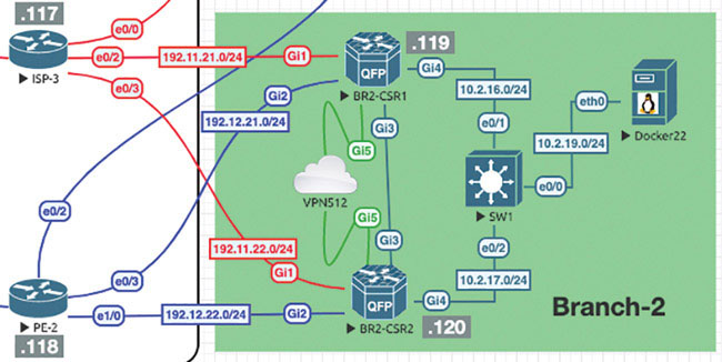
Next we will prepare BR2-CSR1 to support the necessary modifications:
BR2-CSR1# config-transaction

admin connected from 127.0.0.1 using console on BR2-CSR1
BR2-CSR1(config)# vrf definition 100
BR2-CSR1(config-vrf)# address-family ipv4
BR2-CSR1(config-ipv4)# exit
BR2-CSR1(config-vrf)# exit
BR2-CSR1(config)# interface GigabitEthernet 4.100
BR2-CSR1(config-if)# vrf forwarding 100
BR2-CSR1(config-if)# encapsulation dot1Q 100
BR2-CSR1(config-if)# ip address 10.2.100.119 255.255.255.0
BR2-CSR1(config-if)# ip mtu 1496
BR2-CSR1(config-if)# no shut
BR2-CSR1(config-if)# exit
BR2-CSR1(config)# vrf definition 200
BR2-CSR1(config-vrf)# address-family ipv4
BR2-CSR1(config-ipv4)# exit
BR2-CSR1(config-vrf)# exit
BR2-CSR1(config)# interface GigabitEthernet 4.200
BR2-CSR1(config-if)# vrf forwarding 200
BR2-CSR1(config-if)# encapsulation dot1Q 200
BR2-CSR1(config-if)# ip address 10.2.200.119 255.255.255.0
BR2-CSR1(config-if)# ip mtu 1496
BR2-CSR1(config-if)# no shut
BR2-CSR1(config-if)# commit
Commit complete.
Next, you can configure SW1 in Branch-2 with the necessary trunking and SVI configurations to support BR2-CSR1 and BR2-CSR2:
Switch# config t
Enter configuration commands, one per line.  End with CNTL/Z.
Switch(config)# no ip domain lookup
Switch(config)# line con 0
Switch(config-line)# logg synch
Switch(config-line)# no exec-timeout
Switch(config-line)# exit
Switch(config)# vlan 100
Switch(config-vlan)# name VPN100
Switch(config-vlan)# vlan 200
Switch(config-vlan)# name VPN200
Switch(config-vlan)# exit
Switch(config)# int range eth 0/1-2
Switch(config-if-range)# switchport trunk encapsulation dot1q
Switch(config-if-range)# switchport mode trunk
Switch(config-if-range)# no shut
Switch(config-if-range)# exit
Switch(config)# hostname BR2-SW1
BR2-SW1(config)# interface vlan 100
BR2-SW1(config-if)# ip address 10.2.100.111 255.255.255.0
BR2-SW1(config-if)# no shut
BR2-SW1(config-if)# interface vlan 200
BR2-SW1(config-if)# ip address 10.2.200.111 255.255.255.0
BR2-SW1(config-if)# no shut
BR2-SW1(config-if)# do wr
Building configuration...
Compressed configuration from 1095 bytes to 726 bytes[OK]
Now you need to test reachability to the interfaces on BR2-CSR1:
BR2-SW1# ping 10.2.100.119
Type escape sequence to abort.
Sending 5, 100-byte ICMP Echos to 10.2.100.119, timeout is 2 seconds:
.!!!!
Success rate is 80 percent (4/5), round-trip min/avg/max = 1/1/1 ms
BR2-SW1# ping 10.2.200.119
Type escape sequence to abort.
Sending 5, 100-byte ICMP Echos to 10.2.200.119, timeout is 2 seconds:
.!!!!
Success rate is 80 percent (4/5), round-trip min/avg/max = 1/1/1 ms
BR2-SW1#
Now you can make the same configuration on BR2-CSR2:
BR2-CSR2# config-transaction

admin connected from 127.0.0.1 using console on BR2-CSR2
BR2-CSR2(config)# vrf definition 100
BR2-CSR2(config-vrf)# address-family ipv4
BR2-CSR2(config-ipv4)# exit
BR2-CSR2(config-vrf)# exit
BR2-CSR2(config)# interface GigabitEthernet 4.100
BR2-CSR2(config-if)# vrf forwarding 100
BR2-CSR2(config-if)# encapsulation dot1Q 100
BR2-CSR2(config-if)# ip address 10.2.100.120 255.255.255.0
BR2-CSR2(config-if)# ip mtu 1496
BR2-CSR2(config-if)# no shut
BR2-CSR2(config-if)# exit
BR2-CSR2(config)# vrf definition 200
BR2-CSR2(config-vrf)# address-family ipv4
BR2-CSR2(config-ipv4)# exit
BR2-CSR2(config-vrf)# exit
BR2-CSR2(config)# interface GigabitEthernet 4.200
BR2-CSR2(config-if)# vrf forwarding 200
BR2-CSR2(config-if)# encapsulation dot1Q 200
BR2-CSR2(config-if)# ip address 10.2.200.120 255.255.255.0
BR2-CSR2(config-if)# ip mtu 1496
BR2-CSR2(config-if)# no shut
BR2-CSR2(config-if)# commit
Commit complete.
See if you can ping SW1 and BR2-CSR1 from BR2-CSR2:
BR2-CSR2# ping vrf 100 10.2.100.111
Type escape sequence to abort.
Sending 5, 100-byte ICMP Echos to 10.2.100.111, timeout is 2 seconds:
!!!!!
Success rate is 100 percent (5/5), round-trip min/avg/max = 1/1/2 ms
BR2-CSR2# ping vrf 100 10.2.100.119
Type escape sequence to abort.
Sending 5, 100-byte ICMP Echos to 10.2.100.119, timeout is 2 seconds:
!!!!!
Success rate is 100 percent (5/5), round-trip min/avg/max = 1/1/1 ms
BR2-CSR2# ping vrf 200 10.2.200.111
Type escape sequence to abort.
Sending 5, 100-byte ICMP Echos to 10.2.200.111, timeout is 2 seconds:
!!!!!

Success rate is 100 percent (5/5), round-trip min/avg/max = 1/1/1 ms
BR2-CSR2# ping vrf 200 10.2.200.119
Type escape sequence to abort.
Sending 5, 100-byte ICMP Echos to 10.2.200.119, timeout is 2 seconds:
!!!!!
Success rate is 100 percent (5/5), round-trip min/avg/max = 1/1/1 ms
Now you need to run routing protocols between the WAN edge routers and the BR2-SW1 switch. You can run EIGRP in VRF/VPN 100 and OSPF in VRF/VPN 200, starting with VPN 100 on BR2-SW1:
BR2-SW1# configure terminal
Enter configuration commands, one per line.  End with CNTL/Z.
BR2-SW1(config)# router eigrp MICRONICS
BR2-SW1(config-router)# address-family ipv4 autonomous-system 100
BR2-SW1(config-router-af)# network 10.2.100.0 0.0.0.255
BR2-SW1(config-router-af)# network 183.2.111.111 0.0.0.0
BR2-SW1(config-router-af)# end
To provide a way of testing the process, you can create a Loopback100 interface to advertise into EIGRP:
BR2-SW1(config)# int lo 100
BR2-SW1(config-if)# ip address 183.2.111.111 255.255.255.255
BR2-SW1(config-if)# end
As shown below, verify that you have two interfaces participating in EIGRP:
BR2-SW1# show ip eigrp interfaces
EIGRP-IPv4 VR(MICRONICS) Address-Family Interfaces for AS(100)
                              Xmit Queue   PeerQ        Mean   Pacing Time  Multicast  Pending
Interface              Peers  Un/Reliable  Un/Reliable  SRTT   Un/Reliable  Flow Timer Routes
Vl100                    0        0/0       0/0           0       0/0            0     0
Lo100                    0        0/0       0/0           0       0/0            0     0
BR2-SW1#
Now you can configure EIGRP on BR2-CSR1:
BR2-CSR1# config-transaction

admin connected from 127.0.0.1 using console on BR2-CSR1
BR2-CSR1(config)# router eigrp MICRONICS
BR2-CSR1(config-router)# address-family ipv4 vrf 100 autonomous-system
100

BR2-CSR1(config-router-af)# network 10.2.100.119 0.0.0.0
BR2-CSR1(config-router-af)# topology base
BR2-CSR1(config-router-af-topology)# commit
Commit complete.

*Aug 28 14:05:06.209: %DUAL-5-NBRCHANGE: EIGRP-IPv4 100: Neighbor
10.2.100.111 (GigabitEthernet4.
100) is up: new adjacency
Now you can do the same configuration on BR2-CSR2:
BR2-CSR2# config-transaction

admin connected from 127.0.0.1 using console on BR2-CSR2
BR2-CSR2(config)# router eigrp MICRONICS
BR2-CSR2(config-router)# address-family ipv4 vrf 100 autonomous-system
100
BR2-CSR2(config-router-af)# network 10.2.100.120 0.0.0.0
BR2-CSR2(config-router-af)# topology base
BR2-CSR2(config-router-af-topology)# commit
Commit complete.
*Aug 28 14:08:56.632: %DUAL-5-NBRCHANGE: EIGRP-IPv4 100: Neighbor
10.2.100.111 (GigabitEthernet4.100)
 is up: new adjacency
As shown below, verify that BR2-SW1 is learning prefixes in VPN 100 as a part of its EIGRP relationship with BR2-CSR1 and BR2-CSR2:
BR2-SW1# show ip route eigrp
Codes: L - local, C - connected, S - static, R - RIP, M - mobile,
B - BGP
       D - EIGRP, EX - EIGRP external, O - OSPF, IA - OSPF inter area
       N1 - OSPF NSSA external type 1, N2 - OSPF NSSA external type 2
       E1 - OSPF external type 1, E2 - OSPF external type 2
       i - IS-IS, su - IS-IS summary, L1 - IS-IS level-1, L2 - IS-IS
level-2
       ia - IS-IS inter area, * - candidate default, U - per-user
static route
       o - ODR, P - periodic downloaded static route, H - NHRP, l -
LISP
       a - application route
       + - replicated route, % - next hop override, p - overrides from
PfR

Gateway of last resort is not set

BR2-SW1#
BR2-SW1 is not learning anything. But you should understand why at this point in your studies. Obviously, OMP is not being redistributed into EIGRP on the WAN edge devices. You can fix this as shown below:
BR2-CSR1# config-transaction

admin connected from 127.0.0.1 using console on BR2-CSR1
BR2-CSR1(config)# router eigrp MICRONICS
BR2-CSR1(config-router)# address-family ipv4 unicast vrf 100
autonomous-system 100
BR2-CSR1(config-router-af)# topology base
BR2-CSR1(config-router-af-topology)# redistribute omp
BR2-CSR1(config-router-af-topology)# commit
Commit complete.
Enter the following on BR2-CSR2:
BR2-CSR2# config-transaction

admin connected from 127.0.0.1 using console on BR2-CSR2
BR2-CSR2(config)# router eigrp MICRONICS
BR2-CSR2(config-router)# address-family ipv4 unicast vrf 100
autonomous-system 100
BR2-CSR2(config-router-af)# topology base
BR2-CSR2(config-router-af-topology)# redistribute omp
BR2-CSR2(config-router-af-topology)# commit
Commit complete.
Return to BR2-SW1 and check for those prefixes, as shown below:
BR2-SW1# show ip route eigrp
Codes: L - local, C - connected, S - static, R - RIP, M - mobile,
B - BGP
       D - EIGRP, EX - EIGRP external, O - OSPF, IA - OSPF inter area
       N1 - OSPF NSSA external type 1, N2 - OSPF NSSA external type 2
       E1 - OSPF external type 1, E2 - OSPF external type 2
       i - IS-IS, su - IS-IS summary, L1 - IS-IS level-1, L2 - IS-IS
level-2
       ia - IS-IS inter area, * - candidate default, U - per-user
static route
       o - ODR, P - periodic downloaded static route, H - NHRP,
l - LISP
       a - application route
       + - replicated route, % - next hop override, p - overrides from
PfR

Gateway of last resort is not set

      10.0.0.0/8 is variably subnetted, 8 subnets, 2 masks

D EX     10.2.12.0/24 [170/5120] via 10.2.100.120, 00:01:01, Vlan100
                      [170/5120] via 10.2.100.119, 00:01:01, Vlan100
D EX     10.2.13.0/24 [170/5120] via 10.2.100.120, 00:01:01, Vlan100
                      [170/5120] via 10.2.100.119, 00:01:01, Vlan100
D EX     10.2.18.0/24 [170/5120] via 10.2.100.120, 00:01:01, Vlan100
                      [170/5120] via 10.2.100.119, 00:01:01, Vlan100
D EX     10.2.99.0/24 [170/5120] via 10.2.100.120, 00:01:01, Vlan100
                      [170/5120] via 10.2.100.119, 00:01:01, Vlan100
      183.1.0.0/32 is subnetted, 2 subnets
D EX     183.1.1.1 [170/5120] via 10.2.100.120, 00:01:01, Vlan100
                   [170/5120] via 10.2.100.119, 00:01:01, Vlan100
D EX     183.1.7.7 [170/5120] via 10.2.100.120, 00:01:01, Vlan100
                   [170/5120] via 10.2.100.119, 00:01:01, Vlan100
BR2-SW1#
You have them! Now test reachability as shown below:
BR2-SW1# ping 183.1.1.1
Type escape sequence to abort.
Sending 5, 100-byte ICMP Echos to 183.1.1.1, timeout is 2 seconds:
.!!!!
Success rate is 80 percent (4/5), round-trip min/avg/max = 1/1/2 ms
BR2-SW1# ping 183.1.7.7
Type escape sequence to abort.
Sending 5, 100-byte ICMP Echos to 183.1.7.7, timeout is 2 seconds:
!!!!!
Success rate is 100 percent (5/5), round-trip min/avg/max = 1/1/2 ms
BR2-SW1# ping 10.2.99.100
Type escape sequence to abort.
Sending 5, 100-byte ICMP Echos to 10.2.99.100, timeout is 2 seconds:
!!!!!
Success rate is 100 percent (5/5), round-trip min/avg/max = 1/1/2 ms
BR2-SW1#
This is great!
Now, for the OSPF configuration on VRF/VPN 200, you can start on BR2-SW1, where you will also create a new SVI interface that you will advertise into OSPF:
BR1-SW1# conf t
Enter configuration commands, one per line.  End with CNTL/Z.
BR1-SW1(config)# int loopback 200
BR1-SW1(config-if)# ip address 183.200.111.111 255.255.255.255
BR1-SW1(config-if)# exit
BR1-SW1(config)# router ospf 1

BR1-SW1(config-router)# router-id 0.0.0.111
BR1-SW1(config-router)# network 183.200.111.111 0.0.0.0 area 0
BR1-SW1(config-router)# network 10.2.200.111 0.0.0.0 area 0
BR1-SW1(config-router)# end
Check to see if you have two interfaces running OSPF:
BR1-SW1# show ip ospf interface brief
Interface    PID   Area        IP Address/Mask    Cost  State Nbrs F/C
Lo200        1     0           183.200.111.111/32 1     LOOP  0/0
Vl200        1     0           10.2.200.111/24    1     DR    0/0
BR1-SW1#
Great! Now you can configure VRF/VPN 200 on the WAN edge devices:
BR2-CSR1# config-transaction

admin connected from 127.0.0.1 using console on BR2-CSR1
BR2-CSR1(config)# router ospf 1 vrf 200
BR2-CSR1(config-router)# router-id 0.0.0.119
BR2-CSR1(config-router)# network 10.2.200.119 0.0.0.0 area 0
BR2-CSR1(config-router)# redistribute omp subnets
BR2-CSR1(config-router)# commit
Commit complete.
Now enter the following on BR2-CSR2:
BR2-CSR2# config-transaction

admin connected from 127.0.0.1 using console on BR2-CSR2
BR2-CSR2(config)# router ospf 1 vrf 200
BR2-CSR2(config-router)# router-id 0.0.0.120
BR2-CSR2(config-router)# network 10.2.200.120 0.0.0.0 area 0
BR2-CSR2(config-router)# redistribute omp subnets
BR2-CSR2(config-router)# commit
Commit complete.
You have done the configuration, but if you take the time to inspect the results from the perspective of BR2-SW1, you will find that you have an issue related to the lack of OSPF neighbor adjacencies, as shown below:
BR1-SW1# show ip ospf neighbor

Neighbor ID   Pri  State           Dead Time   Address        Interface
0.0.0.119     1    EXCHANGE/DR     00:00:36    10.2.200.119   Vlan200
0.0.0.120     1    EXCHANGE/BDR    00:00:37    10.2.200.120   Vlan200
BR1-SW1#
You can see that BR2-SW1 is in the EXCHANGE state. Further inspection from the BR2 WAN edge routers shows that they are stuck in EXSTART:
BR2-CSR2# show ip ospf neighbor

Neighbor ID     Pri   State           Dead Time   Address         Interface
0.0.0.111         1   EXSTART/DROTHER 00:00:39    10.2.200.111    GigabitEthernet4.200
0.0.0.119         1   FULL/DR         00:00:31    10.2.200.119    GigabitEthernet4.200
BR2-CSR2#
Notice that BR2-CSR2 has formed a full relationship with BR2-CSR1 but has failed to form a neighborship with BR2-SW1. This is because of the MTU mismatch between the devices. The WAN edges agree on the MTU (1496), but the switch is running 1500. You need to correct this issue. There are two ways you can do this. One way is to change the MTU to 1496:
BR1-SW1# conf t
Enter configuration commands, one per line.  End with CNTL/Z.
BR1-SW1(config)# int vlan 200
BR1-SW1(config-if)# ip mtu 1496
BR1-SW1(config-if)# exit
BR1-SW1(config)#
*Aug 28 15:11:46.928: %OSPF-5-ADJCHG: Process 1, Nbr 0.0.0.120 on
Vlan200 from LOADING to FULL, Loading Done
BR1-SW1(config)#
*Aug 28 15:12:16.293: %OSPF-5-ADJCHG: Process 1, Nbr 0.0.0.119 on
Vlan200 from LOADING to FULL, Loading Done
Now as a last verification, you need to see if BR1-SW1 is learning OSPF routes:
BR1-SW1# show ip route ospf
Codes: L - local, C - connected, S - static, R - RIP, M - mobile,
B - BGP
       D - EIGRP, EX - EIGRP external, O - OSPF, IA - OSPF inter area
       N1 - OSPF NSSA external type 1, N2 - OSPF NSSA external type 2
       E1 - OSPF external type 1, E2 - OSPF external type 2
       i - IS-IS, su - IS-IS summary, L1 - IS-IS level-1, L2 - IS-IS
level-2
       ia - IS-IS inter area, * - candidate default, U - per-user
static route
       o - ODR, P - periodic downloaded static route, H - NHRP,
l - LISP
       a - application route
       + - replicated route, % - next hop override, p - overrides from
PfR

Gateway of last resort is not set


      10.0.0.0/8 is variably subnetted, 9 subnets, 2 masks
O E2     10.2.14.0/24 [110/16777214] via 10.2.200.120, 00:03:19,
Vlan200
                      [110/16777214] via 10.2.200.119, 00:03:19,
Vlan200
      172.101.0.0/24 is subnetted, 1 subnets
O E2     172.101.2.0 [110/16777214] via 10.2.200.120, 00:03:19, Vlan200
                     [110/16777214] via 10.2.200.119, 00:03:19, Vlan200
When you test for learned routes, you also want to see reachability, as shown below:
BR1-SW1# ping 10.2.14.121
Type escape sequence to abort.
Sending 5, 100-byte ICMP Echos to 10.2.14.121, timeout is 2 seconds:
!!!!!
Success rate is 100 percent (5/5), round-trip min/avg/max = 1/1/1 ms
BR1-SW1# ping 172.101.2.111
Type escape sequence to abort.
Sending 5, 100-byte ICMP Echos to 172.101.2.111, timeout is 2 seconds:
.!!!!
Success rate is 80 percent (4/5), round-trip min/avg/max = 1/1/2 ms
BR1-SW1# ping 172.101.2.112
Type escape sequence to abort.
Sending 5, 100-byte ICMP Echos to 172.101.2.112, timeout is 2 seconds:
!!!!!
Success rate is 100 percent (5/5), round-trip min/avg/max = 1/1/2 ms
BR1-SW1#
You have completed the unicast routing configuration for Branch-2.
Lab 4: Configuring vEdge Using a Feature Template
For this lab, you need to configure BR1-vE1 by using a vManage template using the information in the matrix provided below. The following pages walk through how to do this.
Device | Feature Template | Template – Name | Values |
|---|---|---|---|
BR1-vE1 | System | BR1-vE1-SYSTEM-temp | Site-id: 11 System-ip: Device Specific Hostname: BR1-vE1 Baud Rate: 115200 |
VPN | BR1-vE1-VPN0-template | VPN ID: 0 DNS: 8.8.8.8 GW1: 0.0.0.0/0 192.11.11.117 GW2: 0.0.0.0/0 192.12.11.118 | |
VPN Interface Ethernet | BR1-vE1-VPN0-ge0_0-template | Shutdown: No Interface Name: ge0/0 Static: 192.11.11.121/24 Tunnel Interface: On Color: Biz-Internet Allow Service: All | |
VPN Interface Ethernet | BR1-vE1-VPN0-ge0_1-template | Shutdown: No Interface Name: ge0/1 Static: 192.12.11.121/24 Tunnel Interface: On Color: MPLS Allow Service: All | |
VPN | BR1-vE1-VPN100-template | VPN ID: 100 | |
VPN Interface Ethernet | BR1-vE1-VPN100-int-ge0_4-template | Shutdown: No Interface Name: ge0/4 Static: 10.2.99.121/24 Tunnel: Off | |
OPSF | BR1-vE1-VPN100-OSPF-template | Redistribute: Connected, Static & OMP Area: 0 Interface: ge0/4 | |
VPN | BR1-vE1-VPN200-template | VPN ID: 200 | |
VPN Interface Ethernet | BR1-vE1-VPN200-int-ge0_2-template | Shutdown: No Interface Name: ge0/2 Static: 10.2.24.121/24 Tunnel: Off | |
VPN | BR1-vE1-vpn512-temp | VPN ID: 512 | |
VPN Interface Ethernet | BR1-vE1-vpn512-int-temp | Shutdown: No Interface Name: eth0 Static: 10.82.83.121/24 | |
Device | Device Template | Template-Name | Values |
BR1-vE1 | vEdge Cloud | BR1-vE1-Device-Template | Use all feature templates created above |
Navigate to Configuration > Templates > Feature in the vManage UI and click Add Template.
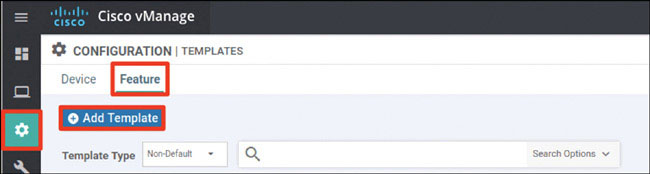
In the screen that appears, scroll down and select vEdge Cloud in the left-hand working pane. Then click System in the Select Template > BASIC INFORMATION section in the right-hand working pane, as shown below:
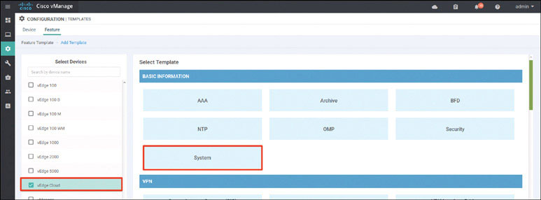
In the following steps, you will provide the information specified in the matrix at the beginning of this lab.
Name the template as shown below:
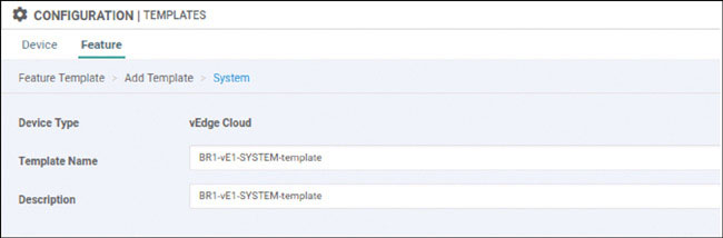
Provide the basic configuration shown below and click Save:
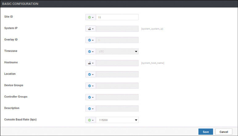
Click Add Template. In the screen that appears, scroll down and select vEdge Cloud in the left-hand working pane. Then choose VPN in the Select Template > VPN section in the right-hand working pane, as shown below:
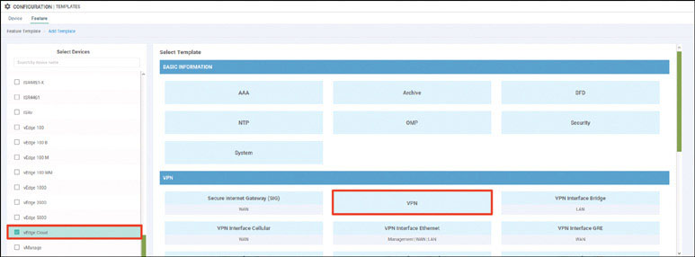
Name the template as shown on the next page:
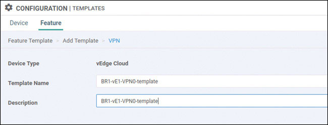
Select Basic Configuration and provide the VPN ID 0, as shown below:
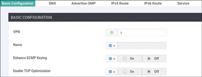
Select DNS and provide the DNS IP address 8.8.8.8, as shown below:
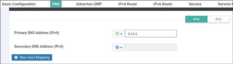
Click IPv4 Route and then click New IPv4 Route, as shown below:
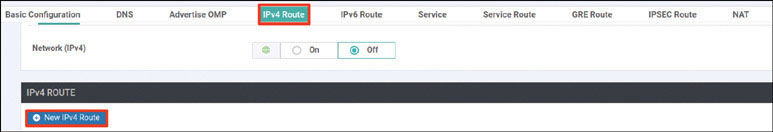
Enter the 0.0.0.0/0 prefix and click Add Next Hop, as shown below:
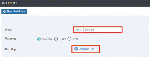
Click Add Next Hop, as shown below:
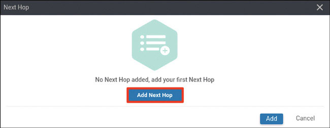
Modify the Next Hop screen as shown below and click Add.
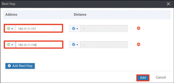
Verify that your screen looks as shown on the next page and click Add:
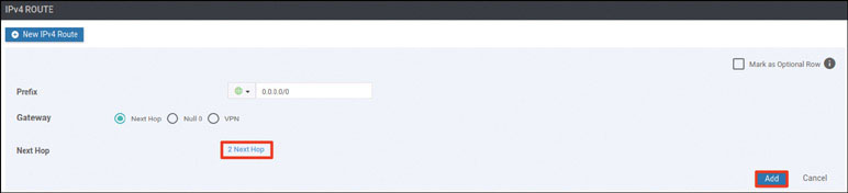
You should see the following information:

Click Save:

Click Add Template. In the screen that appears, scroll down and select vEdge Cloud in the left-hand working pane. Then click VPN Interface Ethernet in the Select Template > VPN section in the right-hand working pane, as shown below:
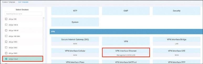
Name the template as shown below:
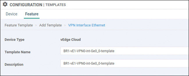
Select Basic Configuration, set Shutdown to No, and enter the interface name ge0/0. Then provide the static IP address 192.11.11.121/24 for this interface, as shown below:

Select Tunnel, set Tunnel Interface to On, and select biz-internet from the Color dropdown, as shown below:
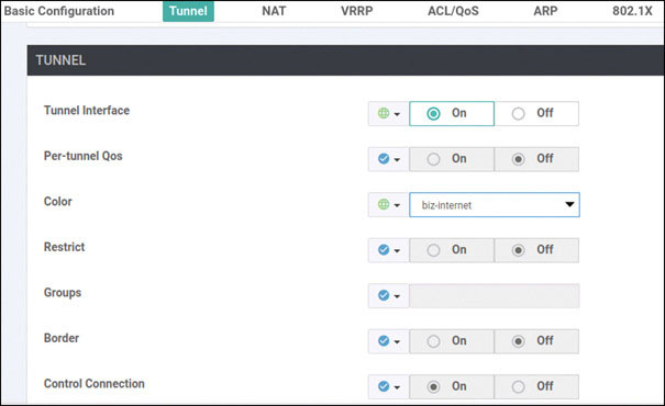
Scroll down to the Allow Service section and set All to On, as shown below:
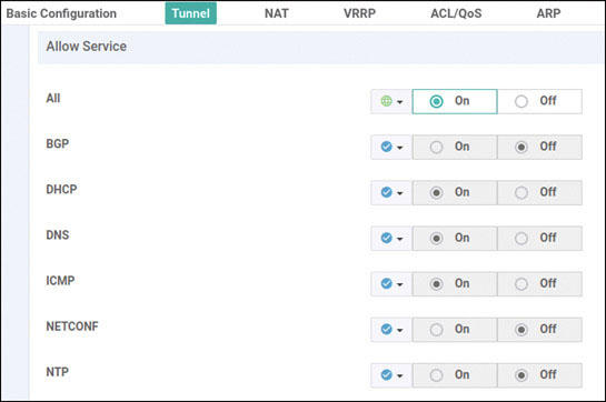
Click Save.
Click Add Template. In the screen that appears, scroll down and select vEdge Cloud in the left-hand working pane. Then click VPN Interface Ethernet in the Select Template > VPN section in the right-hand working pane, as shown below:
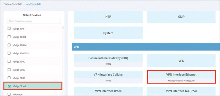
Name the template as shown below:
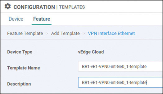
Select Basic Configuration, set Shutdown to No, and enter the interface name ge0/1. Then provide the static IP address 192.12.11.121/24 for this interface, as shown below:

Select Tunnel, set Tunnel Interface to On, and select mpls from the Color dropdown, as shown below:
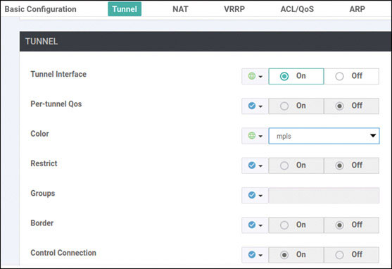
Scroll down to the Allow Service section and set All to On, as shown below:
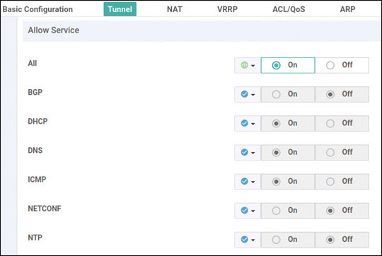
Click Save.
Click Add Template. In the screen that appears, scroll down and select vEdge Cloud in the left-hand working pane. Then click VPN in the Select Template > VPN section in the right-hand working pane, as shown below:
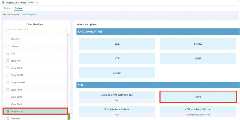
Name the template as shown below:
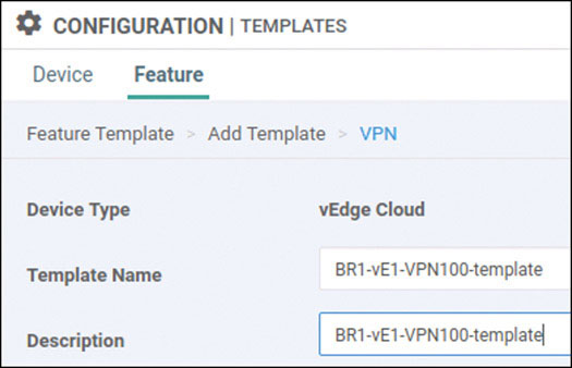
Select Basic Configuration and provide the VPN ID 100, as shown below:
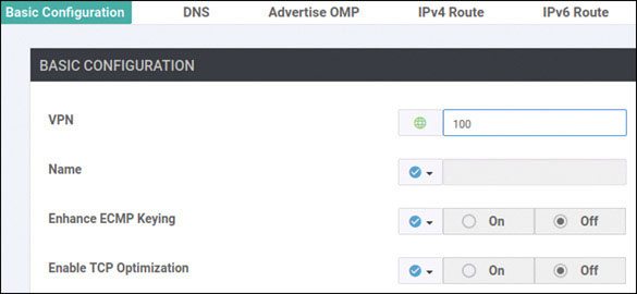
Click Save.
Click Add Template. In the screen that appears, scroll down and select vEdge Cloud in the left-hand working pane. Then click OSPF in the Select Template > OTHER TEMPLATES section in the right-hand working pane, as shown below:
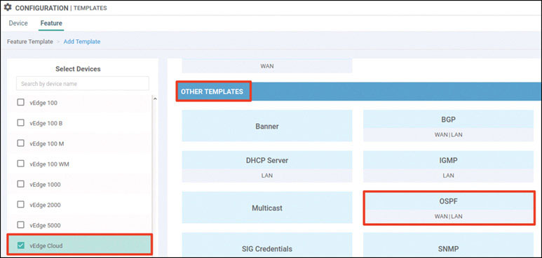
Name the template as shown below:
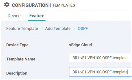
Select Redistribute and then click New Redistribution, as shown below:
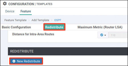
Set Protocol to omp and click Add:
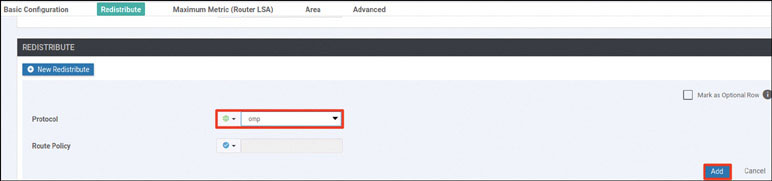
Select Area and click New Area:
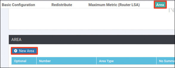
Enter the area number of 0 and click Add Interface, as shown below:

Click Add Interface, as shown below:
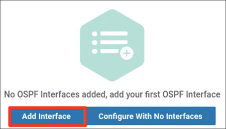
Provide the interface name ge0/4 and click Add:
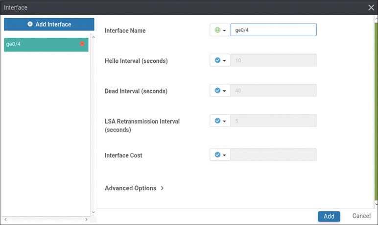
Click Add again:

Click Save.
Click Add Template. In the screen that appears, scroll down and select vEdge Cloud in the left-hand working pane. Then click VPN Interface Ethernet in the Select Template > VPN section in the right-hand working pane, as shown below:
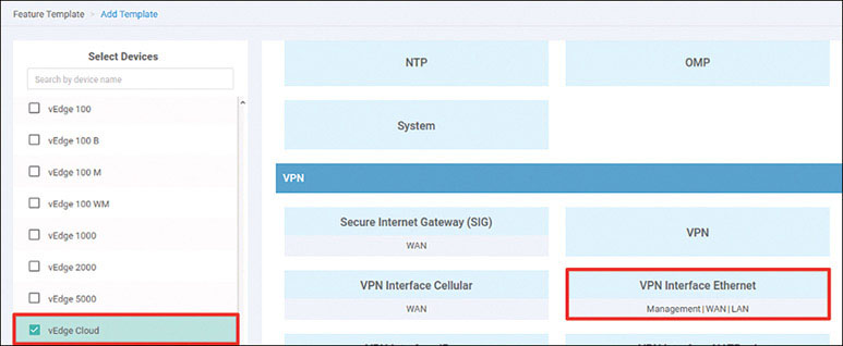
Name the template as shown below:
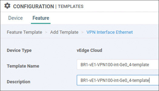
Select Basic Configuration, set Shutdown to No, and enter the interface name ge0/4. Then provide the static IP address 10.2.99.121/24 for this interface, as shown below:

Click Save.
Click Add Template. In the screen that appears, scroll down and select vEdge Cloud in the left-hand working pane. Then click VPN in the Select Template > VPN section in the right-hand working pane, as shown on the next page:
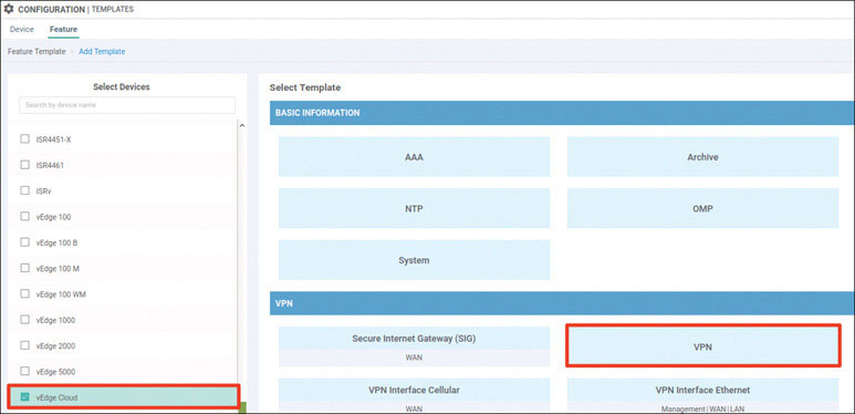
Name the template as shown below:
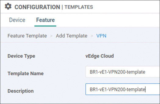
Select Basic Configuration and provide the VPN ID 200, as shown below:
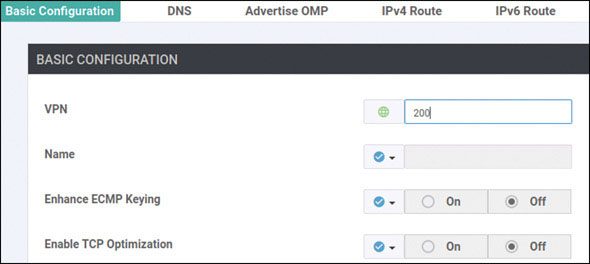
Click Save.
Click Add Template. In the screen that appears, scroll down and select vEdge Cloud in the left-hand working pane. Then click VPN Interface Ethernet in the Select Template > VPN section in the right-hand working pane, as shown below:
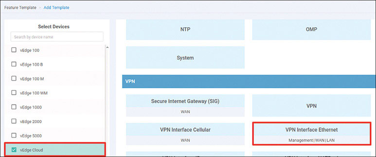
Name the template as shown below:
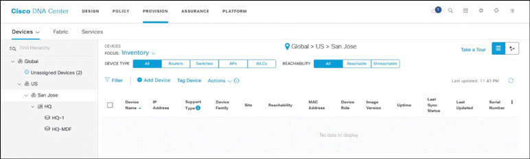
Select Basic Configuration, set Shutdown to No, and enter the interface name ge0/2. Then provide the static IP address 10.2.14.121/24 for this interface, as shown on the next page:
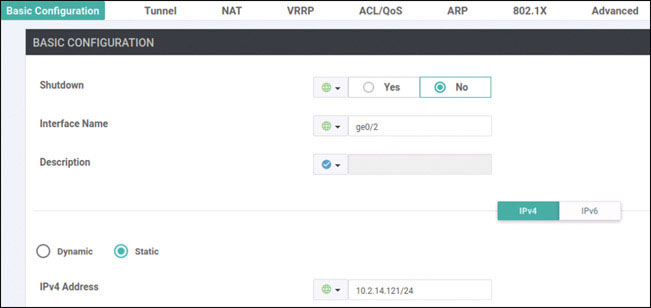
Click Save.
Click Add Template. In the screen that appears, scroll down and select vEdge Cloud in the left-hand working pane. Then click VPN in the Select Template > VPN section in the right-hand working pane, as shown below:
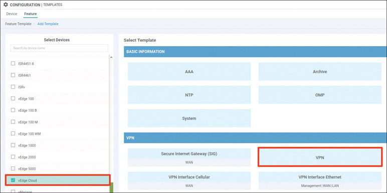
Name the template as shown below:
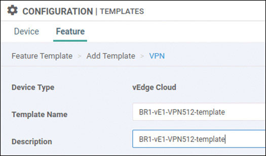
Select Basic Configuration and provide the VPN ID 512, as shown below:
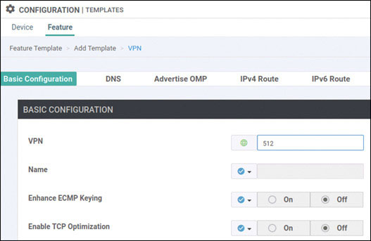
Click Save.
Click Add Template. In the screen that appears, scroll down and select vEdge Cloud in the left-hand working pane. Then click VPN Interface Ethernet in the Select Template > VPN section in the right-hand working pane, as shown below:
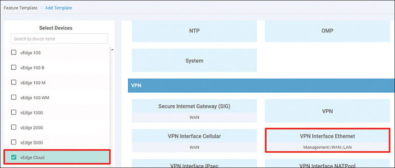
Name the template as shown below:
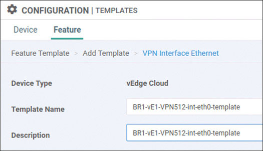
Select Basic Configuration, set Shutdown to No, and enter the interface name eth0. Then provide the static IP address 10.82.83.121/24 for this interface, as shown below:
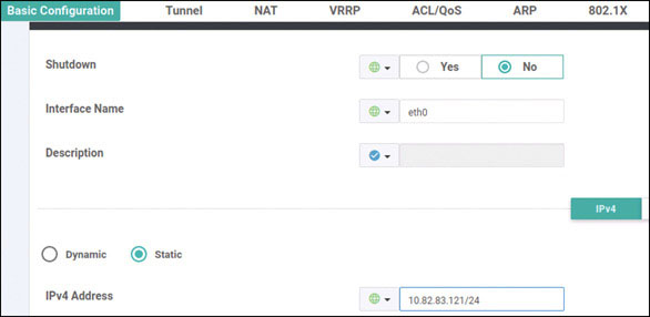
Click Save.
Navigate to Configuration > Templates > Device > Create Template and select From Feature Template. Select vEdge Cloud from the Device Model List dropdown and name the template as shown below:
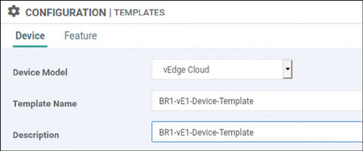
Select Basic Information and make the changes shown below:
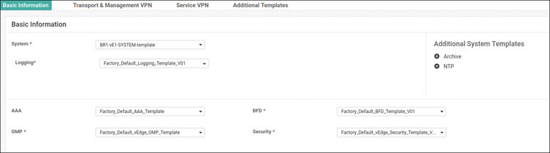
Select Transport & Management VPN and make the changes shown below:
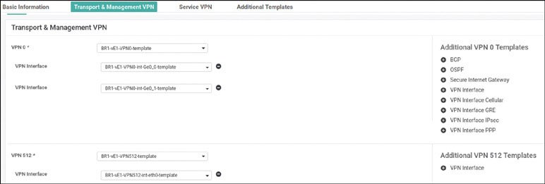
Select Service VPN and click Add VPN:
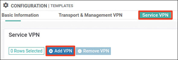
In the Available VPN Templates pane, select BR1-vE1-VPN100-template and click the right-pointing arrow to move selected template to the right-hand working pane:
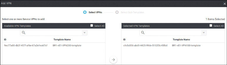
Click Next.

Modify the Add VPN window as shown below:
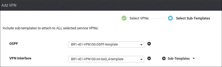
Click Add.
Click Add VPN again:
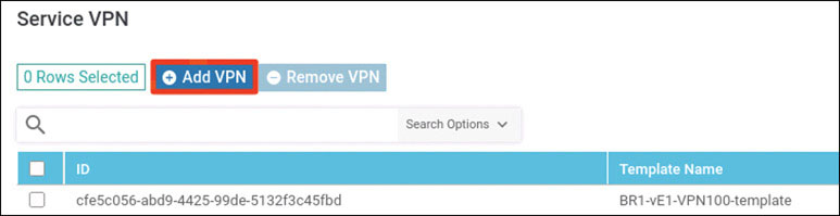
In the Available VPN Templates pane, select BR1-vE1-VPN200-template and click the right-pointing arrow to move it to the right-hand working pane:
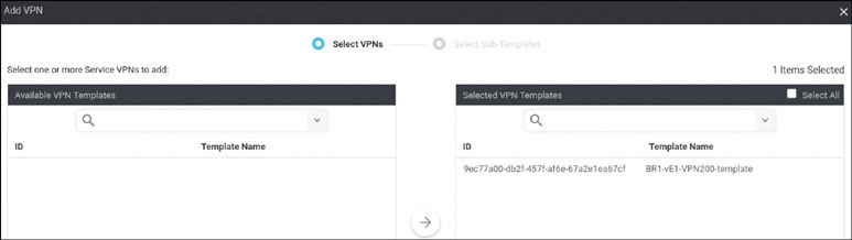
Modify the Add VPN window as shown below:
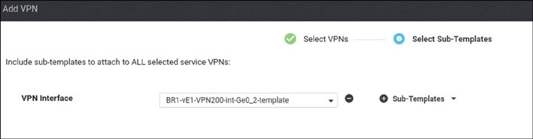
Click Add.
To complete the device template, click Create:

Attach this template to BR1-vE1 by clicking the … icon at the right of the following line and selecting Attach Devices, as shown below:
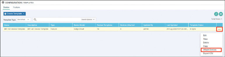
In the Attach Devices window select BR1-vE1 in the Available Devices pane and click the right-pointing arrow to move the device to the Selected Devices pane. Then click Attach:
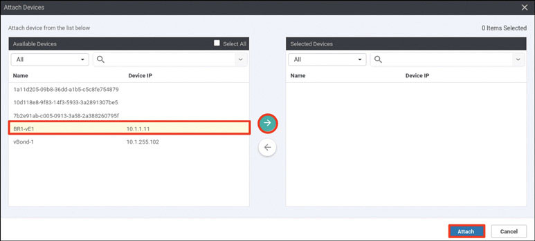
You now see the device template listed on the next screen. You should see a green circle with a check mark at the far-left side of the screen, as shown below. If you see it, click Next:
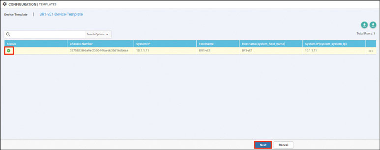
In the list of devices, select BR1-vE1 and verify the configuration that will be pushed to the device. When you are satisfied with the configuration, click Configure Devices.

After a few moments, you should see the following:
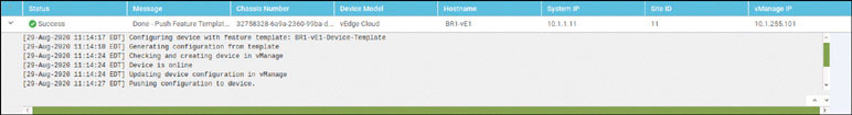
To test this deployment to make sure everything works, you can enter the pings shown below on Docker23 to see if you can reach VPN 200 resources in the other sites:
root@Docker23:~# ping 10.2.200.111 -c 5 ← Loopback of BR2-SW1
PING 10.2.200.111 (10.2.200.111) 56(84) bytes of data.
64 bytes from 10.2.200.111: icmp_seq=1 ttl=253 time=1.28 ms
64 bytes from 10.2.200.111: icmp_seq=2 ttl=253 time=1.32 ms
64 bytes from 10.2.200.111: icmp_seq=3 ttl=253 time=1.09 ms
64 bytes from 10.2.200.111: icmp_seq=4 ttl=253 time=1.48 ms
64 bytes from 10.2.200.111: icmp_seq=5 ttl=253 time=1.31 ms

--- 10.2.200.111 ping statistics ---
5 packets transmitted, 5 received, 0% packet loss, time 4003ms
rtt min/avg/max/mdev = 1.098/1.301/1.481/0.122 ms

root@Docker23:~# ping 172.101.2.111 -c 5 ← DC1-CSR1 Gi3
PING 172.101.2.111 (172.101.2.111) 56(84) bytes of data.
64 bytes from 172.101.2.111: icmp_seq=1 ttl=254 time=1.85 ms
64 bytes from 172.101.2.111: icmp_seq=2 ttl=254 time=1.59 ms
64 bytes from 172.101.2.111: icmp_seq=3 ttl=254 time=1.56 ms
64 bytes from 172.101.2.111: icmp_seq=4 ttl=254 time=1.62 ms
64 bytes from 172.101.2.111: icmp_seq=5 ttl=254 time=1.17 ms

--- 172.101.2.111 ping statistics ---
5 packets transmitted, 5 received, 0% packet loss, time 4006ms
rtt min/avg/max/mdev = 1.175/1.562/1.852/0.218 ms

root@Docker23:~# ping 172.101.2.112 -c 5 ← DC1-CSR2 Gi3
PING 172.101.2.112 (172.101.2.112) 56(84) bytes of data.
64 bytes from 172.101.2.112: icmp_seq=1 ttl=254 time=1.88 ms
64 bytes from 172.101.2.112: icmp_seq=2 ttl=254 time=1.38 ms
64 bytes from 172.101.2.112: icmp_seq=3 ttl=254 time=3.19 ms
64 bytes from 172.101.2.112: icmp_seq=4 ttl=254 time=1.22 ms
64 bytes from 172.101.2.112: icmp_seq=5 ttl=254 time=1.03 ms

--- 172.101.2.112 ping statistics ---
5 packets transmitted, 5 received, 0% packet loss, time 4002ms
rtt min/avg/max/mdev = 1.030/1.742/3.192/0.779 ms
root@Docker23:~#
Now you can test reachability in VRF/VPN 100 from RM-R1:
RM-R1# ping 183.1.7.7 ← Loopback of HQ-R7
Type escape sequence to abort.
Sending 5, 100-byte ICMP Echos to 183.1.7.7, timeout is 2 seconds:
!!!!!
Success rate is 100 percent (5/5), round-trip min/avg/max = 1/1/2 ms
RM-R1# ping 10.2.100.111 ← SVI VLAN100 of BR2-SW1
Type escape sequence to abort.
Sending 5, 100-byte ICMP Echos to 10.2.100.111, timeout is 2 seconds:
!!!!!
Success rate is 100 percent (5/5), round-trip min/avg/max = 1/1/2 ms
RM-R1#
You can see that all reachability has been resolved in Branch-1.
Lab 5: Configuring vEdge Using a vManage Feature Template
For this lab, you need to configure BR1-vE1 by using a vManage template using the information in the matrix provided below. The following pages walk through how to do this.
Device | Feature Template | Template – Name | Values |
|---|---|---|---|
BR1-vE1 | System | BR1-vE1-SYSTEM-temp | Site-id: 11 System-ip: Device Specific Hostname: BR1-vE1 Baud Rate: 115200 |
VPN | BR1-vE1-VPN0-template | VPN ID: 0 DNS: 8.8.8.8 GW1: 0.0.0.0/0 192.11.11.117 GW2: 0.0.0.0/0 192.12.11.118 | |
VPN Interface Ethernet | BR1-vE1-VPN0-ge0_0-template | Shutdown: No Interface Name: ge0/0 Static: 192.11.11.121/24 Tunnel Interface: On Color: Biz-Internet Allow Service: All | |
VPN Interface Ethernet | BR1-vE1-VPN0-ge0_1-template | Shutdown: No Interface Name: ge0/1 Static: 192.12.11.121/24 Tunnel Interface: On Color: MPLS Allow Service: All | |
VPN | BR1-vE1-VPN100-template | VPN ID: 100 | |
VPN Interface Ethernet | BR1-vE1-VPN100-int-ge0_4-template | Shutdown: No Interface Name: ge0/4 Static: 10.2.99.121/24 Tunnel: Off | |
OPSF | BR1-vE1-VPN100-OSPF-template | Redistribute: Connected, Static & OMP Area: 0 Interface: ge0/4 | |
VPN | BR1-vE1-VPN200-template | VPN ID: 200 | |
VPN Interface Ethernet | BR1-vE1-VPN200-int-ge0_2-template | Shutdown: No Interface Name: ge0/2 Static: 10.2.24.121/24 Tunnel: Off | |
VPN | BR1-vE1-vpn512-temp | VPN ID: 512 | |
VPN Interface Ethernet | BR1-vE1-vpn512-int-temp | Shutdown: No Interface Name: eth0 Static: 10.82.83.121/24 | |
Device | Device Template | Template-Name | Values |
BR1-vE1 | vEdge Cloud | BR1-vE1-Device-Template | Use all feature templates created above |
Navigate to Configuration > Templates > Feature in the vManage UI and click Add Template:
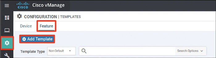
In the screen that appears, scroll down and select vEdge Cloud in the left-hand working pane. Then click System in the Select Template > BASIC INFORMATION section in the right-hand working pane, as shown below:
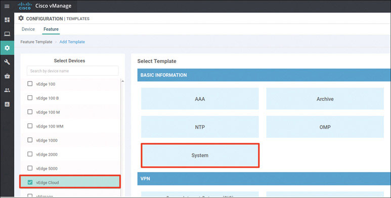
In the following steps, you will provide the information specified in the matrix at the beginning of this lab.
Name the template as shown below:
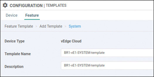
Provide the basic configuration information shown below and click Save:
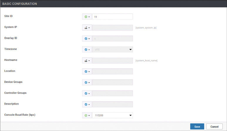
Click Add Template. In the screen that appears, scroll down and select vEdge Cloud in the left-hand working pane. Then click VPN in the Select Template > VPN section in the right-hand working pane, as shown on the next page:
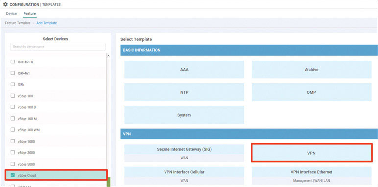
Name the template as shown below:
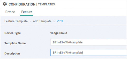
Select Basic Configuration and provide the VPN ID 0, as shown below:
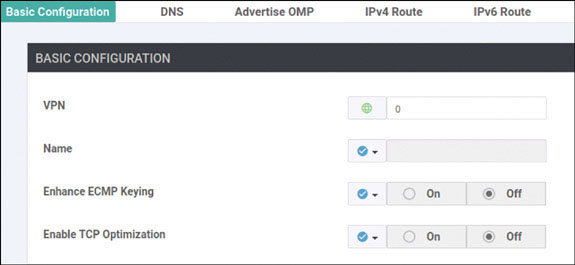
Select DNS and provide the DNS IP address 8.8.8.8, as shown below:
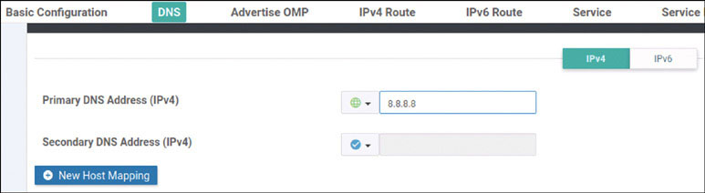
Select IPv4 Route and click New IPv4 Route:
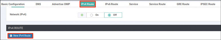
Enter the 0.0.0.0/0 prefix and click Add Next Hop:
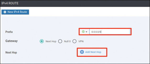
Click Add Next Hop:
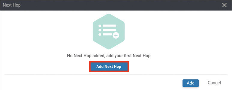
Modify the Next Hop screen as shown below and click Add:
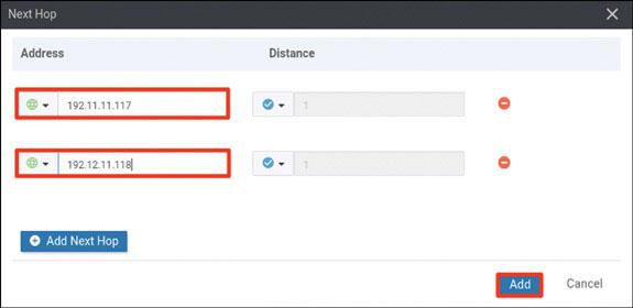
Verify that your screen looks as shown below and click Add:
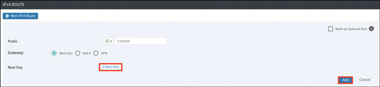
You should see the following information:

Click Save.
Click Add Template. In the screen that appears, scroll down and select vEdge Cloud in the left-hand working pane. Then click VPN Interface Ethernet in the Select Template > VPN section in the right-hand working pane, as shown below:
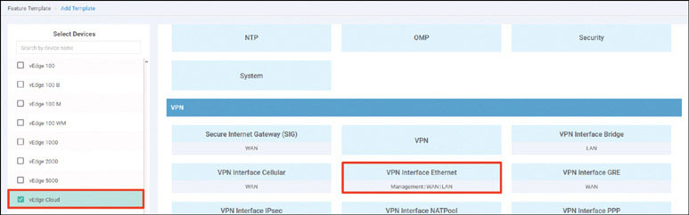
Name the template as shown below:
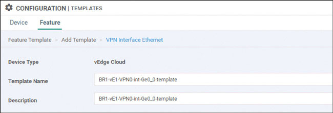
Select Basic Configuration, set Shutdown to No, and enter the interface name ge0/0. Then provide the static IP address 192.11.11.121/24 for this interface, as shown below:

Select Tunnel, set Tunnel Interface to On, and select biz-internet from the Color dropdown, as shown below:

Scroll down to the Allow Service section and set All to On, as shown below:
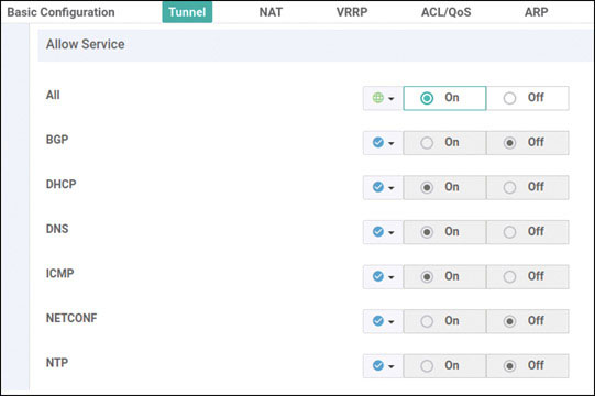
Click Save.
Click Add Template. In the screen that appears, scroll down and select vEdge Cloud in the left-hand working pane. Then click VPN Interface Ethernet in the Select Template > VPN section in the right-hand working pane, as shown below:
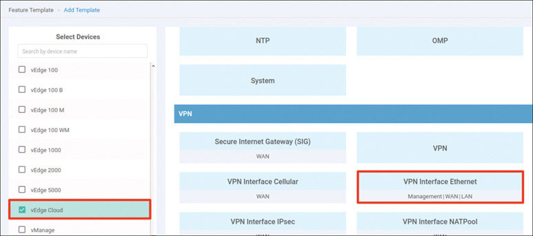
Name the template as shown below:
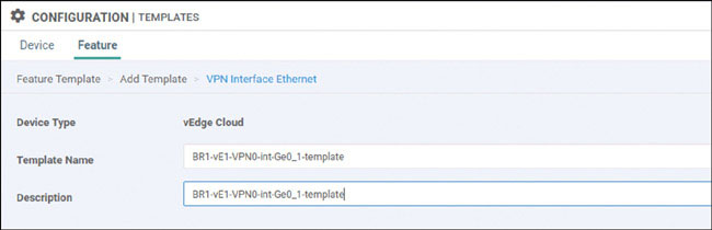
Select Basic Configuration, set Shutdown to No, and enter the interface name ge0/1. Then provide the static IP address 192.12.11.121/24 for this interface, as shown below:
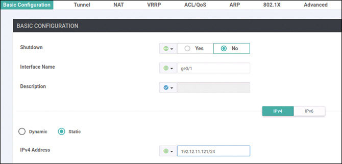
Select Tunnel, set Tunnel Interface to On, and select mpls from the Color dropdown, as shown below:

Scroll down to the Allow Service section and set All to On, as shown below:

Click Save.
Click Add Template. In the screen that appears, scroll down and select vEdge Cloud in the left-hand working pane. Then click VPN in the Select Template > VPN section in the right-hand working pane, as shown below:
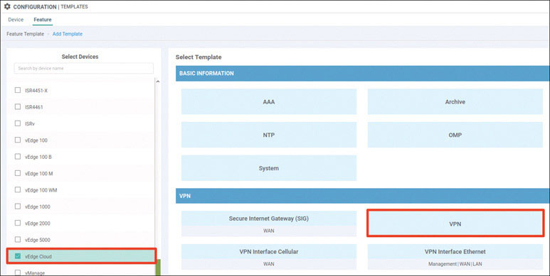
Name the template as shown below:
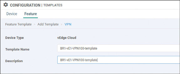
Select Basic Configuration and provide the VPN ID 100, as shown below:
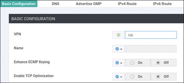
Click Save.
Click Add Template. In the screen that appears, scroll down and select vEdge Cloud in the left-hand working pane. Then click OSPF in the Select Template > OTHER TEMPLATES section in the right-hand working pane, as shown below:
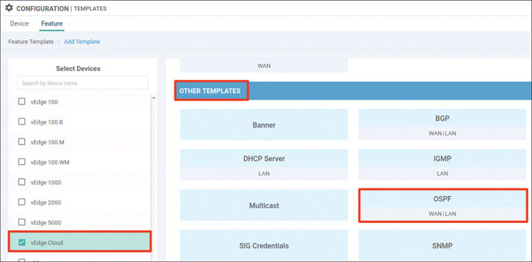
Name the template as shown below:
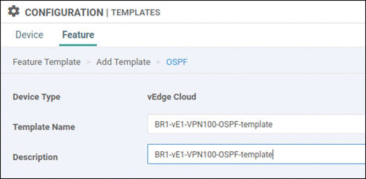
Select Redistribute and click New Redistribution:
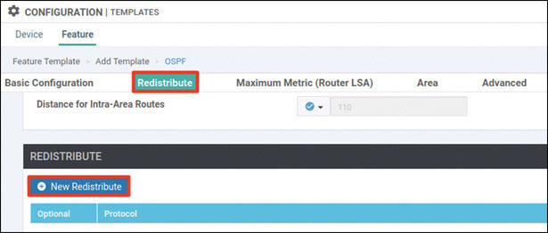
Select omp from the Protocol dropdown and click Add:
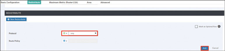
Select Area and click New Area:
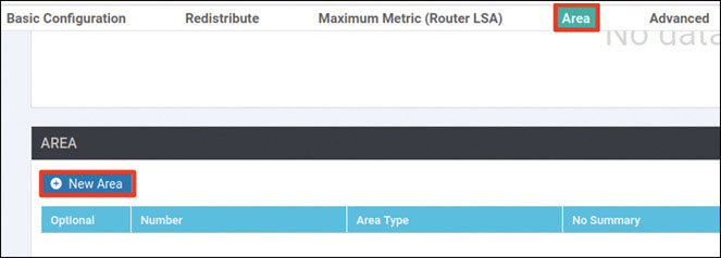
Enter the area number 0 and click Add Interface:
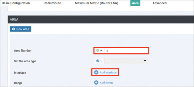
Click Add Interface, as shown below:
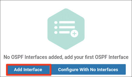
Provide the interface name ge0/4 and click Add:

Click Add again.
Click Save.
Click Add Template. In the screen that appears, scroll down and select vEdge Cloud in the left-hand working pane. Then click VPN Interface Ethernet in the Select Template > VPN section in the right-hand working pane, as shown below:
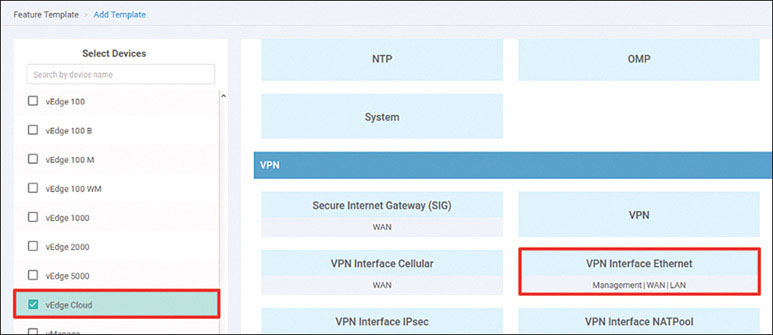
Name the template as shown below:
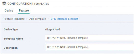
Select Basic Configuration, set Shutdown to No, and enter the interface name ge0/4. Then provide the static IP address 10.2.99.121/24 for this interface, as shown below:
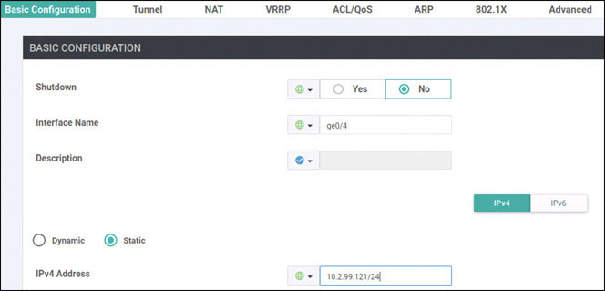
Click Save.
Click Add Template. In the screen that appears, scroll down and select vEdge Cloud in the left-hand working pane. Then click VPN in the Select Template > VPN section in the right-hand working pane, as shown below:

Name the template as shown below:
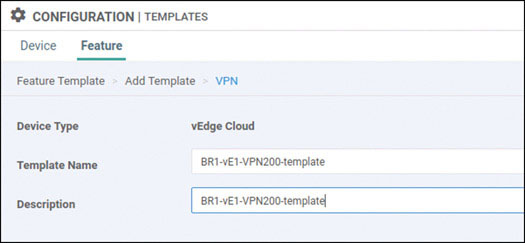
Select Basic Configuration and provide the VPN ID 200, as shown below:
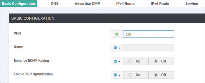
Click Save.
Click Add Template. In the screen that appears, scroll down and select vEdge Cloud in the left-hand working pane. Then click VPN Interface Ethernet in the Select Template > VPN section in the right-hand working pane, as shown below:

Name the template as shown below:
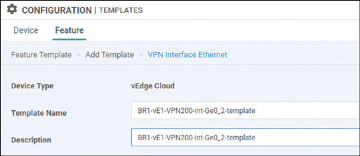
Select Basic Configuration, set Shutdown to No, and enter the interface name ge0/2. Then provide the static IP address 10.2.14.121/24 for this interface, as shown below:
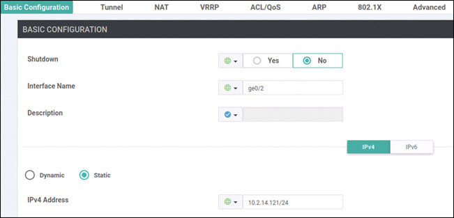
Click Save.
Click Add Template. In the screen that appears, scroll down and select vEdge Cloud in the left-hand working pane. Then click VPN in the Select Template > VPN section in the right-hand working pane, as shown below:
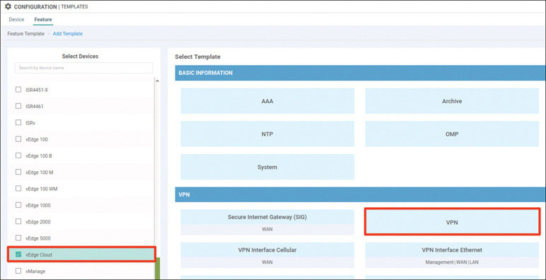
Name the template as shown below:
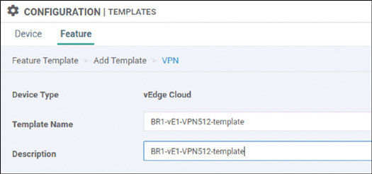
Select Basic Configuration and provide the VPN ID 512, as shown below:
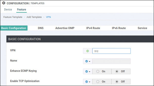
Click Save.
Click Add Template. In the screen that appears, scroll down and select vEdge Cloud in the left-hand working pane. Then click VPN Interface Ethernet in the Select Template > VPN section in the right-hand working pane, as shown below:
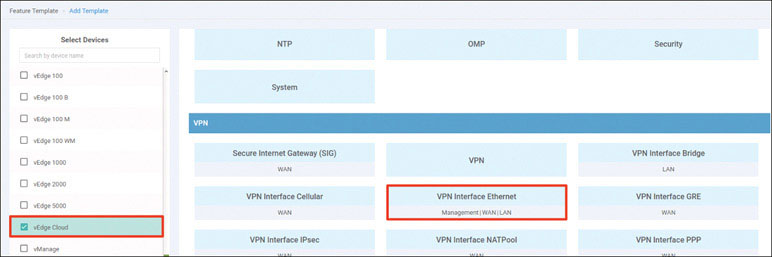
Name the template as shown below:
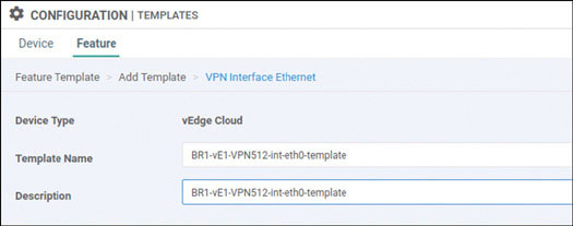
Select Basic Configuration, set Shutdown to No, and enter the interface name eth0. Then provide the static IP address 10.82.83.121/24 for this interface, as shown below:
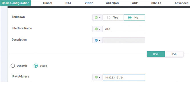
Click Save.
Navigate to Configuration > Templates > Device > Create Template and select From Feature Template. Select vEdge Cloud from the Device Model dropdown and name the template as shown below:
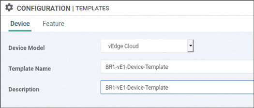
Select Basic Information and make the changes shown below:
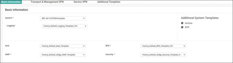
Select Transport & Management VPN and make the changes shown below:
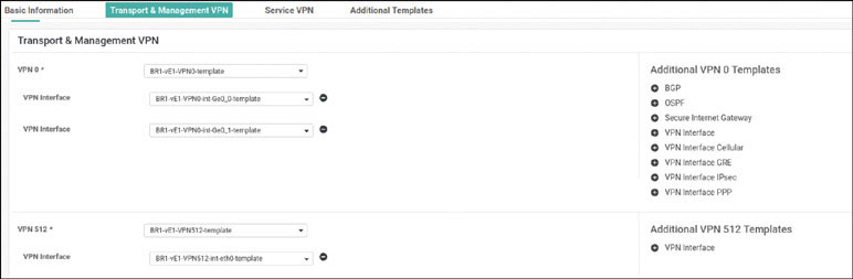
Select Service VPN and click Add VPN:
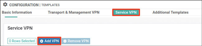
In the Available VPN Templates pane, select BR1-vE1-VPN100-template and click the right-pointing arrow to move selected template to the right-hand working pane:
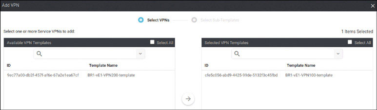
Click Next.
Modify the Add VPN window as shown below:
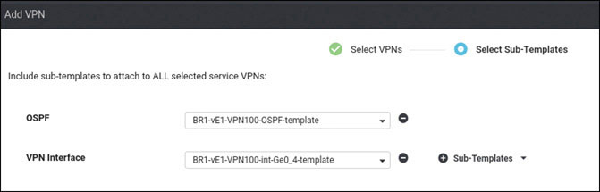
Click Add.
Click Add VPN again.
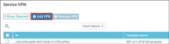
In the Available VPN Templates pane, select BR1-vE1-VPN200-template and click the right-pointing arrow to move selected template to the right-hand working pane:
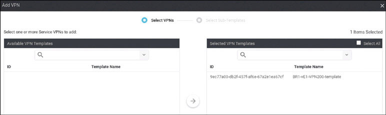
Modify the Add VPN window as shown below:
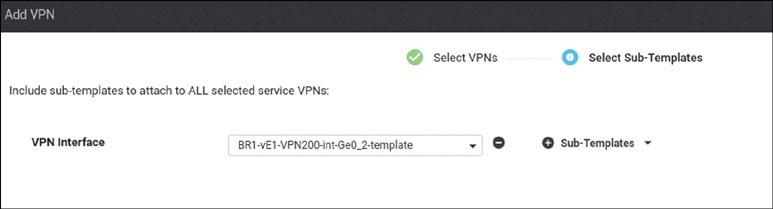
Click Add.
To complete the device template, click Create.
Attach this template to BR1-vE1 by clicking the … icon at the right of the following line and selecting Attach Devices, as shown below:
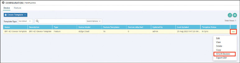
In the Attach Devices window select BR1-vE1 in the Available Devices pane and click the right-pointing arrow to move the device to the Selected Devices pane. Then click Attach:
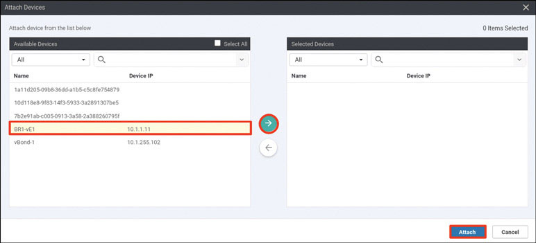
You now see the device template listed on the next screen. You should see a green circle with a check mark at the far-left side of the screen, as shown below. If you see it, click Next:
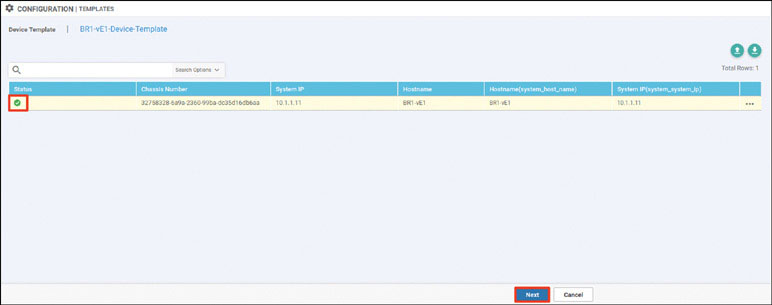
In the list of devices, select BR1-vE1 and verify the configuration that will be pushed to the device. When you are satisfied with the configuration, click Configure Devices.
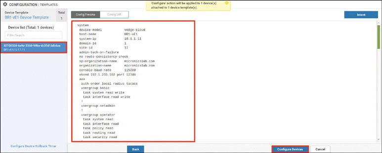
After a few moments, you should see the following:
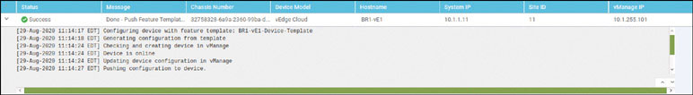
To test this deployment to make sure everything works, you can enter the pings shown below on Docker23 to see if you can reach VPN 200 resources in the other sites:
root@Docker23:~# ping 10.2.200.111 -c 5 ← Loopback of BR2-SW1
PING 10.2.200.111 (10.2.200.111) 56(84) bytes of data.
64 bytes from 10.2.200.111: icmp_seq=1 ttl=253 time=1.28 ms
64 bytes from 10.2.200.111: icmp_seq=2 ttl=253 time=1.32 ms
64 bytes from 10.2.200.111: icmp_seq=3 ttl=253 time=1.09 ms
64 bytes from 10.2.200.111: icmp_seq=4 ttl=253 time=1.48 ms
64 bytes from 10.2.200.111: icmp_seq=5 ttl=253 time=1.31 ms

--- 10.2.200.111 ping statistics ---
5 packets transmitted, 5 received, 0% packet loss, time 4003ms
rtt min/avg/max/mdev = 1.098/1.301/1.481/0.122 ms

root@Docker23:~# ping 172.101.2.111 -c 5 ← DC1-CSR1 Gi3
PING 172.101.2.111 (172.101.2.111) 56(84) bytes of data.
64 bytes from 172.101.2.111: icmp_seq=1 ttl=254 time=1.85 ms
64 bytes from 172.101.2.111: icmp_seq=2 ttl=254 time=1.59 ms
64 bytes from 172.101.2.111: icmp_seq=3 ttl=254 time=1.56 ms
64 bytes from 172.101.2.111: icmp_seq=4 ttl=254 time=1.62 ms
64 bytes from 172.101.2.111: icmp_seq=5 ttl=254 time=1.17 ms


--- 172.101.2.111 ping statistics ---
5 packets transmitted, 5 received, 0% packet loss, time 4006ms
rtt min/avg/max/mdev = 1.175/1.562/1.852/0.218 ms

root@Docker23:~# ping 172.101.2.112 -c 5 ← DC1-CSR2 Gi3
PING 172.101.2.112 (172.101.2.112) 56(84) bytes of data.
64 bytes from 172.101.2.112: icmp_seq=1 ttl=254 time=1.88 ms
64 bytes from 172.101.2.112: icmp_seq=2 ttl=254 time=1.38 ms
64 bytes from 172.101.2.112: icmp_seq=3 ttl=254 time=3.19 ms
64 bytes from 172.101.2.112: icmp_seq=4 ttl=254 time=1.22 ms
64 bytes from 172.101.2.112: icmp_seq=5 ttl=254 time=1.03 ms

--- 172.101.2.112 ping statistics ---
5 packets transmitted, 5 received, 0% packet loss, time 4002ms
rtt min/avg/max/mdev = 1.030/1.742/3.192/0.779 ms
root@Docker23:~#
Now test reachability in VRF/VPN 100 from RM-R1:
RM-R1# ping 183.1.7.7 ← Loopback of HQ-R7
Type escape sequence to abort.
Sending 5, 100-byte ICMP Echos to 183.1.7.7, timeout is 2 seconds:
!!!!!
Success rate is 100 percent (5/5), round-trip min/avg/max = 1/1/2 ms
RM-R1# ping 10.2.100.111 ← SVI VLAN100 of BR2-SW1
Type escape sequence to abort.
Sending 5, 100-byte ICMP Echos to 10.2.100.111, timeout is 2 seconds:
!!!!!
Success rate is 100 percent (5/5), round-trip min/avg/max = 1/1/2 ms
RM-R1#
You can see that all reachability has been resolved in Branch-1.
Lab 6: Configuring cEdge Using a BR-2–Specific vManage Feature Template
For this lab, you need to configure BR2-CSR by using a vManage template using the information in the matrix provided on the next page. The following pages walk through how to do this.
Device | Feature Template | Template – Name | Values |
|---|---|---|---|
BR2-Site-CSRs | System | BR2-CSR-SYSTEM-temp | Site-id: 2 System-ip: Device Specific Hostname: Device Specific Baud Rate: 115200 |
VPN | BR2-CSR-VPN0-template | VPN ID: 0 DNS: 8.8.8.8 GW1: 0.0.0.0/0 device specific gw-inet GW2: 0.0.0.0/0 device specific gw-mpls | |
VPN Interface Ethernet | BR2-CSR-VPN0-int-g1-template | Shutdown: No Interface Name: GigabitEthernet1 Static: device specific g1-ip Tunnel Interface: On Color: Biz-Internet Allow Service: All | |
VPN Interface Ethernet | BR2-CSR-VPN0-int-g2-template | Shutdown: No Interface Name: GigabitEthernet2 Static: device specific g2-ip Tunnel Interface: On Color: MPLS Allow Service: All | |
VPN | BR2-CSR-VPN100-template | VPN ID: 100 | |
VPN Interface Ethernet | BR2-CSR-VPN100-int-g4.100-template | Shutdown: No Interface Name: GigabitEthernet4.100 MTU: 1496 Static: device specific g4_100-ip Tunnel: Off | |
EIGRP | BR2-CSR-VPN100-EIGRP-template | Redistribute: OMP Interface: GigabitEthernet4.100 | |
VPN | BR2-CSR-VPN200-template | VPN ID: 200 | |
VPN Interface Ethernet | BR2-CSR-VPN200-int-g3.200-template | Shutdown: No Interface Name: GigabitEthernet4.200 MTU: 1496 Static: device specific g4_100-ip Tunnel: Off | |
OPSF | BR2-CSR-VPN200-OSPF-template | Redistribute: OMP Area: 0 Interface: GigabitEthernet4.200 | |
VPN | BR2-CSR-vpn512-temp | VPN ID: 512 | |
VPN Interface Ethernet | BR2-CSR-vpn512-int-temp | Shutdown: No Interface Name: GigabitEthernet5 Static: device-specific g5-ip | |
Device | Device Template | Template-Name | Values |
BR2-CSR | CSR1000v | BR2-CSR-Device-Template | Use all feature templates created above |
Navigate to Configuration > Templates > Feature in the vManage UI and click Add Template:
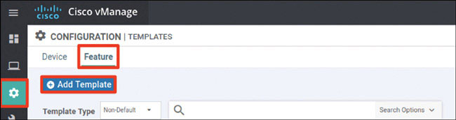
In the screen that appears, scroll down and select CSR1000v in the left-hand working pane. Then choose Cisco System in the Select Template > BASIC INFORMATION section in the right-hand working pane.
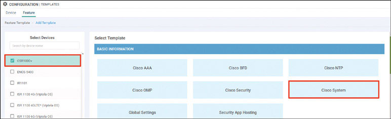
In the following steps, you will provide the information specified in the matrix at the beginning of this lab.
Name the template as shown below:
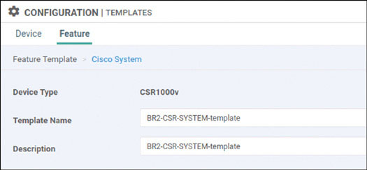
Provide the basic configuration shown below and click Save:
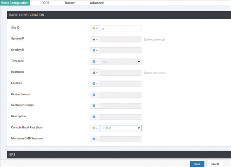
Click Add Template. In the screen that appears, scroll down and select CSR1000v in the left-hand working pane. Then click VPN in the Select Template > VPN section in the right-hand working pane, as shown below:
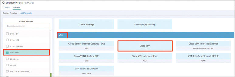
Name the template as shown below:
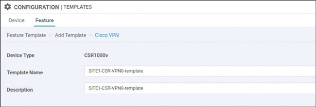
Select Basic Configuration and provide the VPN ID 0:
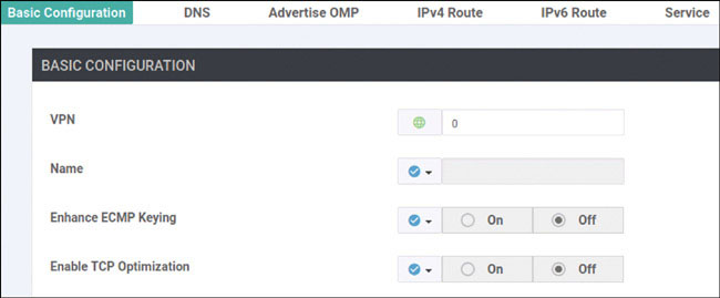
Select DNS and provide the DNS IP address 8.8.8.8:
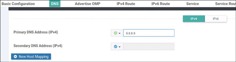
Select IPv4 Route and click New IPv4 Route:
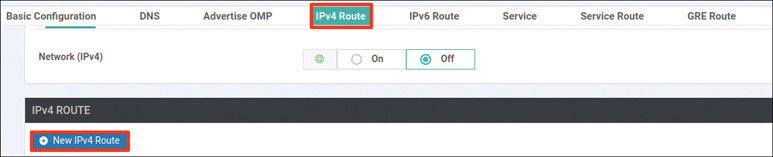
Now enter the prefix 0.0.0.0/0 and click Add Next Hop:
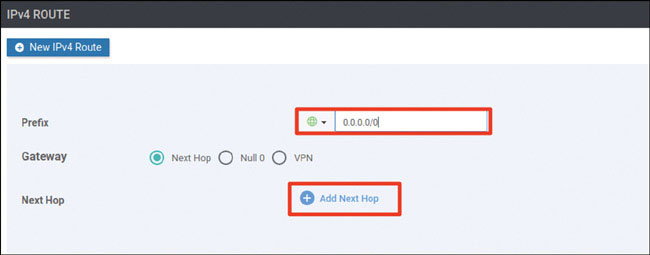
Click Add Next Hop:
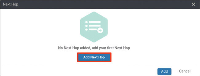
Modify the Next Hop screen as shown below and click Add.
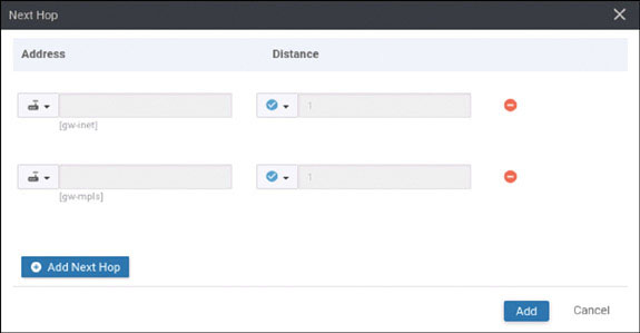
Verify that your screen looks as shown below and click Add:
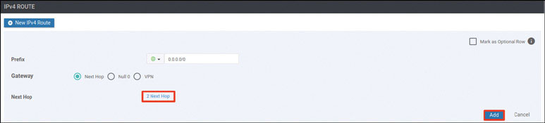
You should see the following information:

Click Save.
Click Add Template. In the screen that appears, scroll down and select CSR1000v in the left-hand working pane. Then click Cisco VPN Interface Ethernet in the Select Template > VPN section in the right-hand working pane, as shown below:
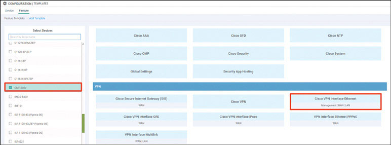
Name the template as shown below:
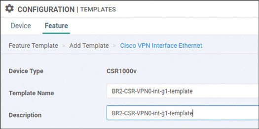
Select Basic Configuration, set Shutdown to No, and enter the interface name GigabitEthernet1. Then select Static and configure a device-specific variable this interface, as shown below:
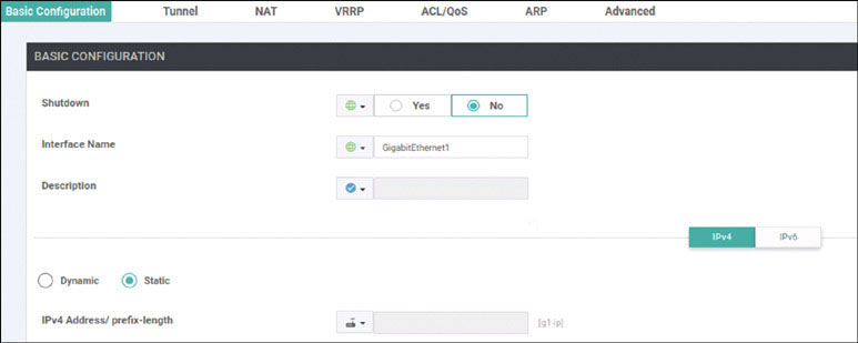
Select Tunnel, set Tunnel Interface to On, and select biz-internet from the Color dropdown, as shown below:
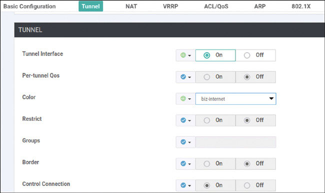
Scroll down to the Allow Service section and set All to On, as shown below:
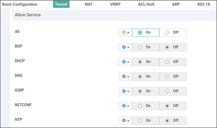
Click Save.
Click Add Template. In the screen that appears, scroll down and select CSR1000v in the left-hand working pane. Then click Cisco VPN Interface Ethernet in the Select Template > VPN section in the right-hand working pane, as shown below:
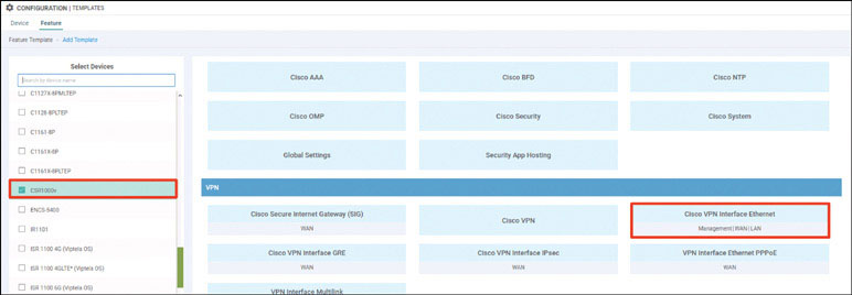
Name the template as shown below:
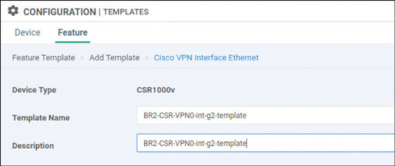
Select Basic Configuration, set Shutdown to No, and enter the interface name GigabitEthernet2. Then select Static and configure a device-specific variable this interface, as shown below:
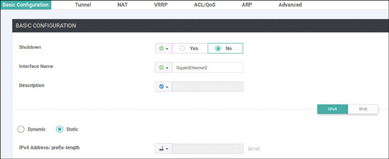
Select Tunnel, set Tunnel Interface to On, and select mpls from the Color dropdown, as shown below:

Scroll down to the Allow Service section and set All to On, as shown below:
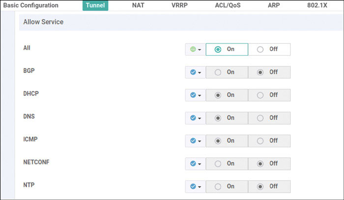
Click Save.
Click Add Template. In the screen that appears, scroll down and select CSR1000v in the left-hand working pane. Then click Cisco VPN in the Select Template > VPN section in the right-hand working pane, as shown below:
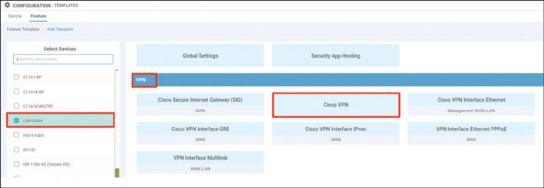
Name the template as shown below:
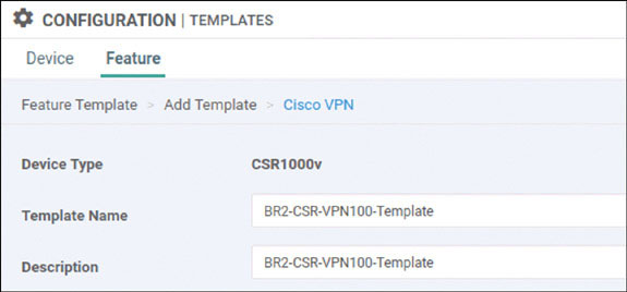
Select Basic Configuration and provide the VPN ID 100:
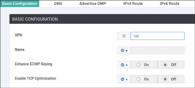
Click Save.
Click Add Template. In the screen that appears, scroll down and select CSR1000v in the left-hand working pane. Then click EIGRP in the Select Template > OTHER TEMPLATES section in the right-hand working pane, as shown below:
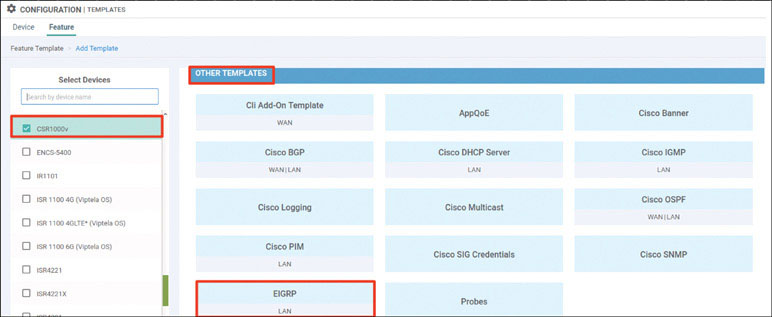
Name the template as shown below:
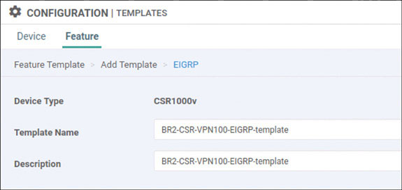
Select IPv4 Unicast Address Family and click New Redistribution:
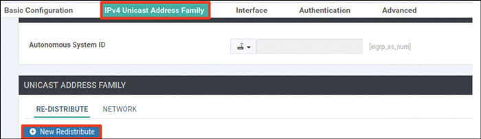
Set Protocol to omp and click Add:
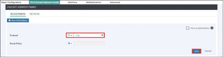
Select Network and click New Network:
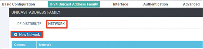
Click Add:
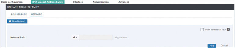
Select Interface and click Interface:
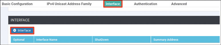
Provide the information shown below and click Add:
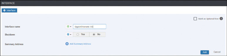
Select Advanced and provide the IP MTU 1496:
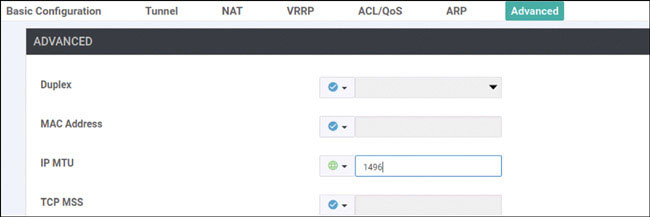
Click Save.
Click Add Template. In the screen that appears, scroll down and select CSR1000v in the left-hand working pane. Then click Cisco VPN Interface Ethernet in the Select Template > VPN section in the right-hand working pane, as shown on the next page:
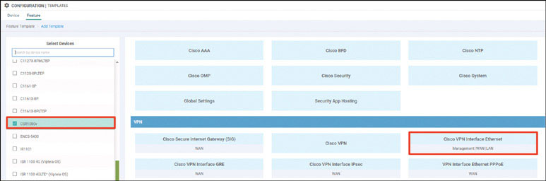
Name the template as shown below:
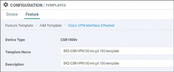
Select Basic Configuration, set Shutdown to No, and enter the interface name GigabitEthernet4.100. Then select Static and configure a device-specific variable this interface, as shown below:
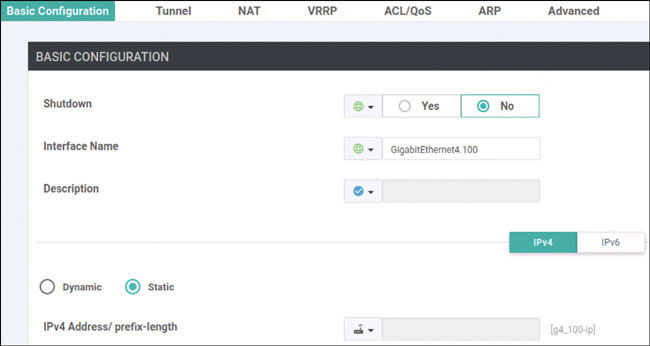
Click Save.
Click Add Template. In the screen that appears, scroll down and select CSR1000v in the left-hand working pane. Then click Cisco VPN in the Select Template > VPN section in the right-hand working pane, as shown on the next page:
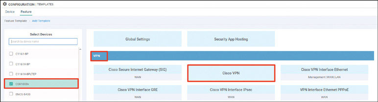
Name the template as shown below:
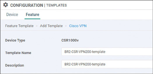
Select Basic Configuration and provide the VPN ID 200:
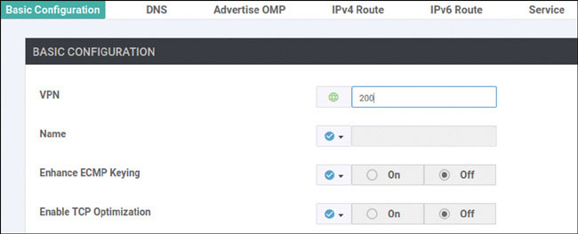
Click Save.
Click Add Template. In the screen that appears, scroll down and select CSR1000v in the left-hand working pane. Then click Cisco OSPF in the Select Template > OTHER TEMPLATES section in the right-hand working pane, as shown on the next page:
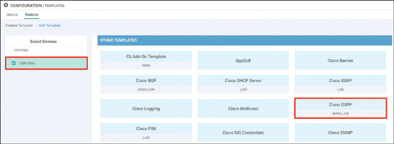
Name the template as shown below:
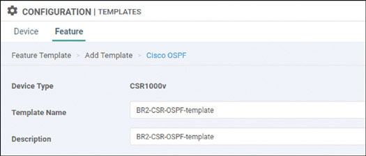
Select Redistribute and click New Redistribute:
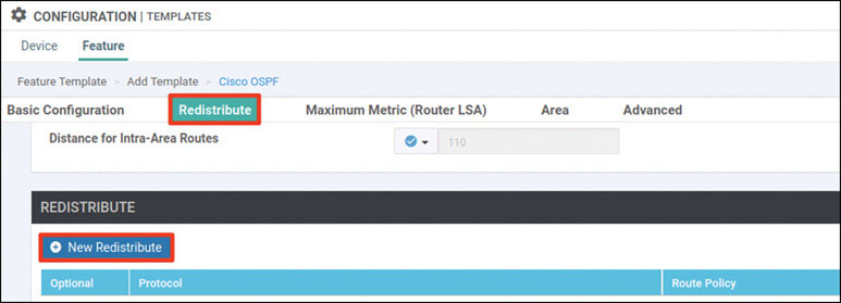
Set Protocol to omp and click Add:
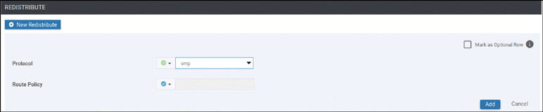
Select Area and click New Area:
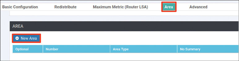
Set Area to 0 and click Add Interface:
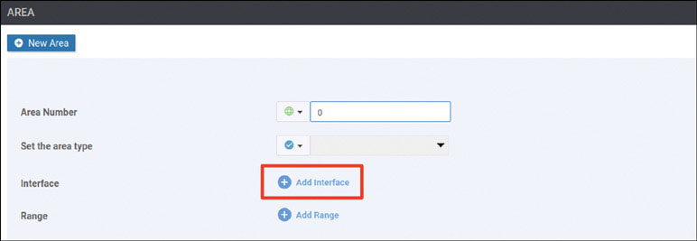
Click Add Interface:
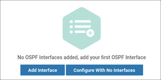
On the Interface screen enter the interface name GigabitEthernet4.200 and click Add:
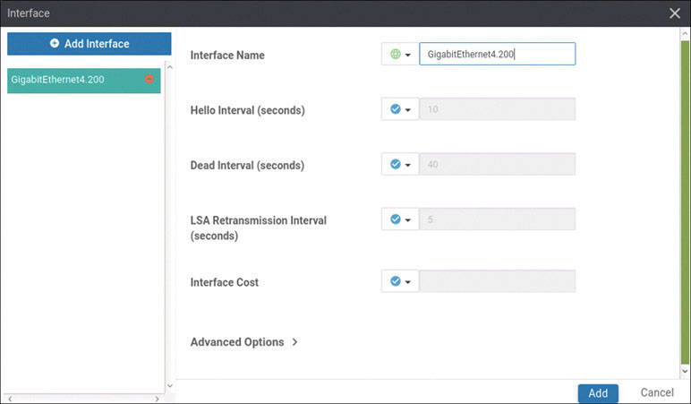
Click Add again and then click Save.
Click Add Template. In the screen that appears, scroll down and select CSR1000v in the left-hand working pane. Then click Cisco VPN Interface Element in the Select Template > VPN section in the right-hand working pane, as shown below:
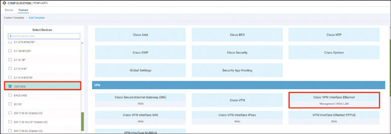
Name the template as shown below:
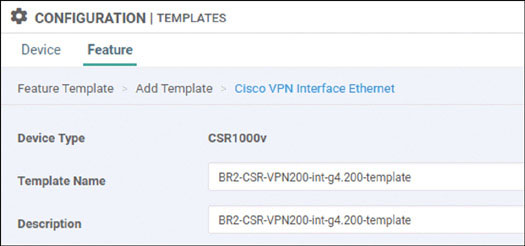
Select Basic Configuration, set Shutdown to No, and enter the interface name GigabitEthernet4.200. Then select Static and configure a device-specific variable this interface, as shown below:
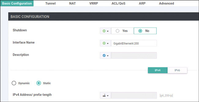
Select Advanced and provide the IP MTU 1496:
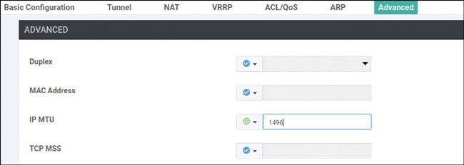
Click Save.
Click Add Template. In the screen that appears, scroll down and select CSR1000v in the left-hand working pane. Then click Cisco VPN in the Select Template > VPN section in the right-hand working pane, as shown below:
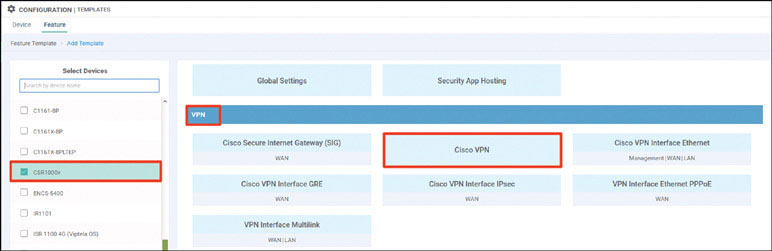
Name the template as shown below:
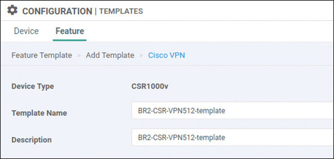
Select Basic Configuration and provide the VPN ID 512:
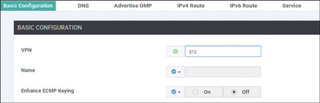
Click Save.
Click Add Template. In the screen that appears, scroll down and select CSR1000v in the left-hand working pane. Then click Cisco VPN Interface Ethernet in the Select Template > VPN section in the right-hand working pane, as shown below:
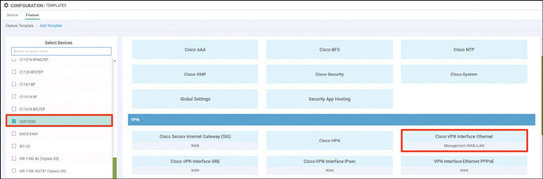
Name the template as shown below:
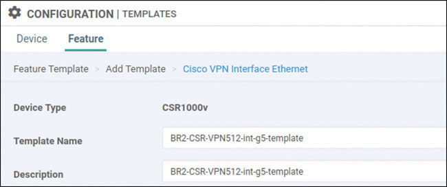
Select Basic Configuration, set Shutdown to No, and enter the interface name GigabitEthernet5. Then select Static and configure a device-specific variable this interface, as shown below:

Click Save.
Navigate to Configuration > Templates > Device > Create Template and select From Feature Template. Select CSR1000v from the Device Model dropdown and name the template as shown below:
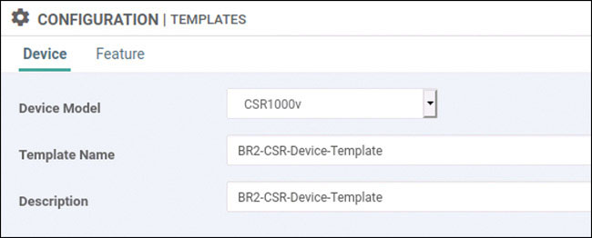
Select Basic Information and make the changes shown below:
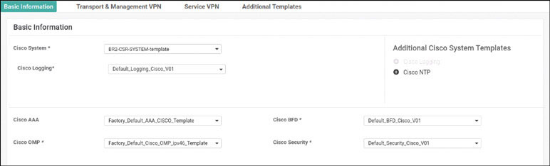
Select Transport & Management VPN and make the changes shown below:
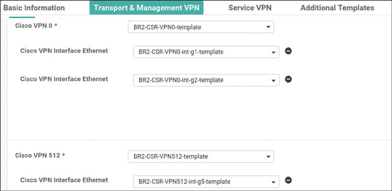
Select Service VPN and click Add VPN:
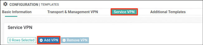
In the Available VPN Templates pane, select BR2-CSR-VPN100-template and click the right-pointing arrow to move selected template to the right-hand working pane:
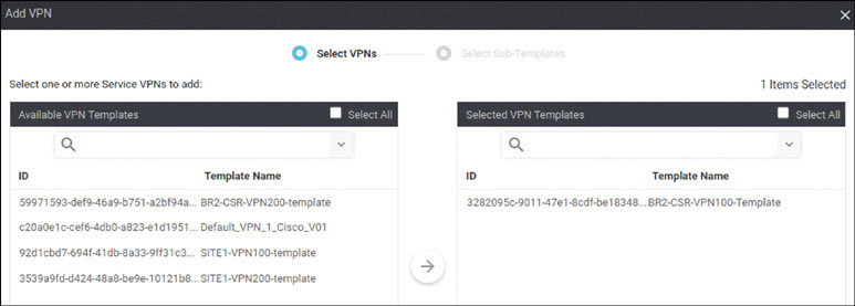
Click Next.
Modify the Add VPN window as shown below:
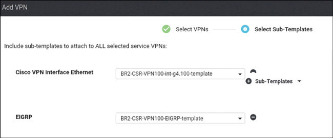
Click Add.
Click Add VPN again:
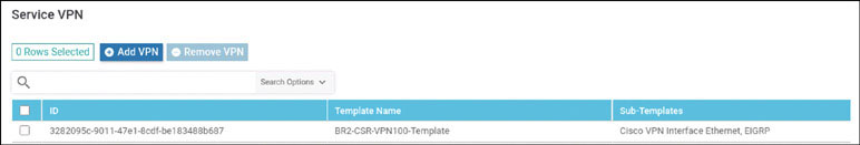
In the Available VPN Templates pane, select BR2-CSR-VPN200-template, click the right-pointing arrow to move selected template to the right-hand working pane, and click Next:
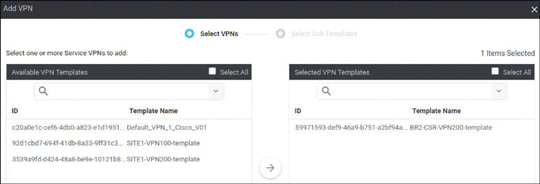
Modify the Add VPN window as shown below:
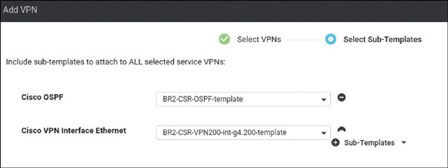
Click Add.
To complete the device template, click Create.
Attach this template to BR2-CSRs by clicking the … icon at the right of the following line and selecting Attach Devices, as shown below:
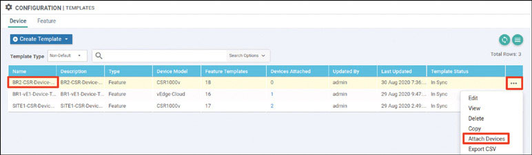
In the Attach Devices window select B1-CSR1 and B2-CSR2 in the Available Devices pane and click the right-pointing arrow to move the device to the Selected Devices pane. Then click Attach:
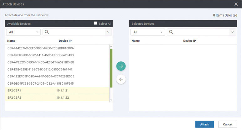
You should see the device template listed in the next screen. Identify the DC1-CSR1 device and click the … icon to the right. Then click Edit Device Template.

In the Update Device Template page, provide the information shown on the next page and click Update:

Find the device BR2-CSR2 and click the … icon, and click Edit Device Template:

On the Update Device Template screen, provide the information shown below and click Update:
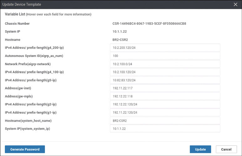
Click Next.
In the list of devices, select BR2-CSR1 and verify the configuration that will be pushed to the device. Repeat the process for BR2-CSR2. When you are satisfied with the configuration, click Configure Devices.
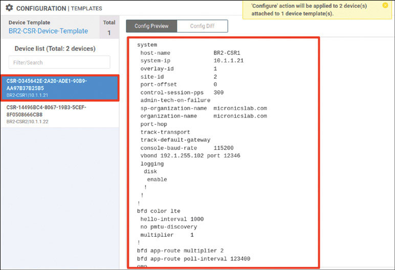
Check Confirm configuration changes on 2 devices and click OK.
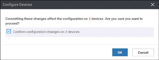
After a few moments, you should see the following:
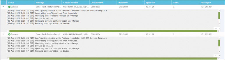
To test this deployment to make sure everything works, you can enter the pings shown below on Docker23 to see if you can reach VPN 200 resources in the other sites:
root@Docker23:~# ping 10.2.200.111 -c 5 ← Loopback of BR2-SW1
PING 10.2.200.111 (10.2.200.111) 56(84) bytes of data.
64 bytes from 10.2.200.111: icmp_seq=1 ttl=253 time=1.28 ms
64 bytes from 10.2.200.111: icmp_seq=2 ttl=253 time=1.32 ms
64 bytes from 10.2.200.111: icmp_seq=3 ttl=253 time=1.09 ms
64 bytes from 10.2.200.111: icmp_seq=4 ttl=253 time=1.48 ms
64 bytes from 10.2.200.111: icmp_seq=5 ttl=253 time=1.31 ms

--- 10.2.200.111 ping statistics ---
5 packets transmitted, 5 received, 0% packet loss, time 4003ms
rtt min/avg/max/mdev = 1.098/1.301/1.481/0.122 ms

root@Docker23:~# ping 172.101.2.111 -c 5 ← DC1-CSR1 Gi3
PING 172.101.2.111 (172.101.2.111) 56(84) bytes of data.
64 bytes from 172.101.2.111: icmp_seq=1 ttl=254 time=1.85 ms
64 bytes from 172.101.2.111: icmp_seq=2 ttl=254 time=1.59 ms
64 bytes from 172.101.2.111: icmp_seq=3 ttl=254 time=1.56 ms
64 bytes from 172.101.2.111: icmp_seq=4 ttl=254 time=1.62 ms
64 bytes from 172.101.2.111: icmp_seq=5 ttl=254 time=1.17 ms

--- 172.101.2.111 ping statistics ---
5 packets transmitted, 5 received, 0% packet loss, time 4006ms
rtt min/avg/max/mdev = 1.175/1.562/1.852/0.218 ms

root@Docker23:~# ping 172.101.2.112 -c 5 ← DC1-CSR2 Gi3
PING 172.101.2.112 (172.101.2.112) 56(84) bytes of data.
64 bytes from 172.101.2.112: icmp_seq=1 ttl=254 time=1.88 ms
64 bytes from 172.101.2.112: icmp_seq=2 ttl=254 time=1.38 ms
64 bytes from 172.101.2.112: icmp_seq=3 ttl=254 time=3.19 ms
64 bytes from 172.101.2.112: icmp_seq=4 ttl=254 time=1.22 ms
64 bytes from 172.101.2.112: icmp_seq=5 ttl=254 time=1.03 ms

--- 172.101.2.112 ping statistics ---
5 packets transmitted, 5 received, 0% packet loss, time 4002ms
rtt min/avg/max/mdev = 1.030/1.742/3.192/0.779 ms
root@Docker23:~#
Test reachability in VRF/VPN 100 from RM-R1:
RM-R1# ping 183.1.7.7 ← Loopback of HQ-R7
Type escape sequence to abort.
Sending 5, 100-byte ICMP Echos to 183.1.7.7, timeout is 2 seconds:
!!!!!

Success rate is 100 percent (5/5), round-trip min/avg/max = 1/1/2 ms
RM-R1# ping 10.2.100.111 ← SVI VLAN100 of BR2-SW1
Type escape sequence to abort.
Sending 5, 100-byte ICMP Echos to 10.2.100.111, timeout is 2 seconds:
!!!!!
Success rate is 100 percent (5/5), round-trip min/avg/max = 1/1/2 ms
RM-R1#
You can see that all reachability has been resolved in HQ Site-1.
Lab 7: Configuring vEdge Using a vManage Feature Template and ZTP
For this lab, you need to configure BR3-vE3 by using a vManage template using the information in the matrix provided below. The following pages walk through how to do this.
Device | Feature Template | Template – Name | Values |
|---|---|---|---|
BR3-vE3 | System | BR3-vE3-SYSTEM-temp | Site-id: 3 System-ip: Device Specific Hostname: BR3-vE3 Baud Rate: 115200 |
VPN | BR3-vE3-VPN0-template | VPN ID: 0 DNS: 8.8.8.8 GW1: 0.0.0.0/0 192.11.33.113 GW2: 0.0.0.0/0 192.12.33.114 | |
VPN Interface Ethernet | BR3-vE3-VPN0-ge0_0-template | Shutdown: No Interface Name: ge0/0 Static: 192.11.33.123/24 Tunnel Interface: On Color: Biz-Internet Allow Service: All | |
VPN Interface Ethernet | BR3-vE3-VPN0-ge0_1-template | Shutdown: No Interface Name: ge0/1 Static: 192.12.33.123/24 Tunnel Interface: On Color: MPLS Allow Service: All | |
VPN | BR3-vE3-VPN100-template | VPN ID: 100 | |
VPN Interface Ethernet | BR3-vE3-VPN100-int-lo100-template | Shutdown: No Interface Name: Loopback100 Static: 10.3.100.123/24 Tunnel: Off | |
VPN | BR3-vE3-VPN200-template | VPN ID: 200 | |
VPN Interface Ethernet | BR3-vE3-VPN200-int-lo200-template | Shutdown: No Interface Name: Loopback200 Static: 10.3.200.121/24 Tunnel: Off | |
VPN | BR3-vE3-VPN300-template | VPN ID: 300 | |
VPN Interface Ethernet | BR3-vE3-VPN200-int-lo200-template | Shutdown: No Interface Name: ge0/2 Static: 10.2.11.121/24 Tunnel: Off | |
VPN | BR3-vE3-vpn512-temp | VPN ID: 512 | |
VPN Interface Ethernet | BR3-vE3-vpn512-int-temp | Shutdown: No Interface Name: eth0 Static: 10.82.83.121/24 | |
Device | Device Template | Template-Name | Values |
BR3-vE3 | vEdge Cloud | BR3-vE3-Device-Template | Use all feature templates created above |
Navigate to Configuration > Templates > Feature in the vManage UI and click Add Template:
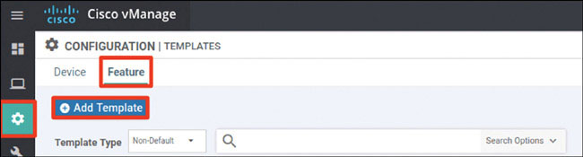
In the screen that appears, scroll down and select vEdge Cloud in the left-hand working pane. Then click System in the Select Template > BASIC INFORMATION section in the right-hand working pane, as shown below:
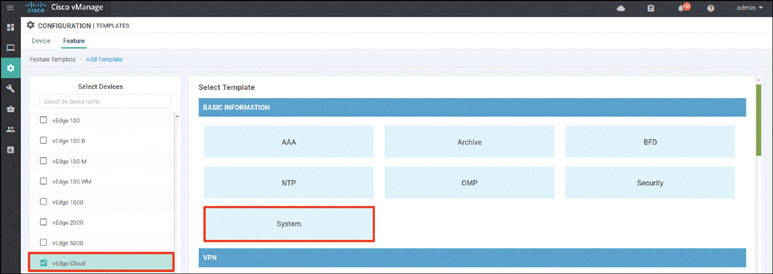
In the following steps, you will provide the information specified in the matrix at the beginning of this lab.
Name the template as shown below:
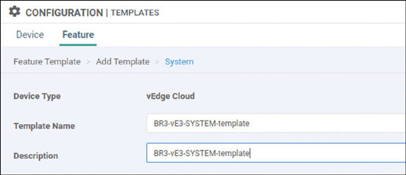
Provide the basic configuration shown below and click Save:
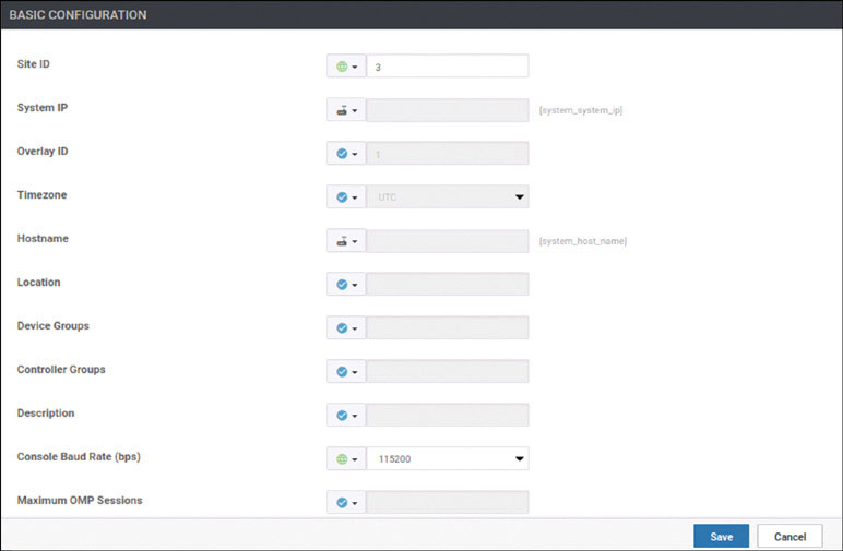
Click Add Template. In the screen that appears, scroll down and select vEdge Cloud in the left-hand working pane. Then click VPN in the Select Template > VPN section in the right-hand working pane, as shown below:
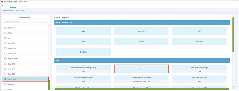
Name the template as shown below:
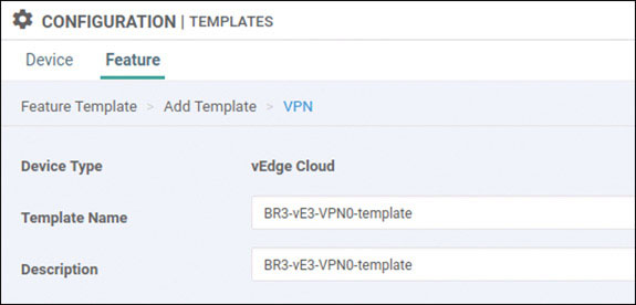
Select Basic Configuration and provide the VPN ID 0:
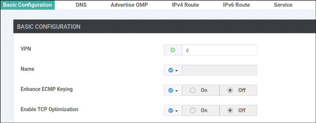
Select DNS and provide the DNS IP address 8.8.8.8:
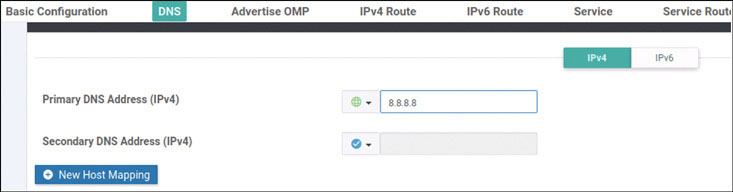
Select IPv4 Route and click New IPv4 Route:
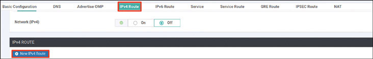
Enter the prefix 0.0.0.0/0 and click Add Next Hop:
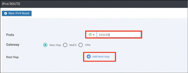
Click Add Next Hop:

Modify the Next Hop screen as shown below and click Add:
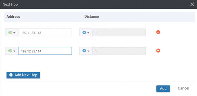
Verify that your screen looks as shown below and click Add:

You should see the following information:

Click Save.
Click Add Template. In the screen that appears, scroll down and select vEdge Cloud in the left-hand working pane. Then click VPN Interface Ethernet in the Select Template > VPN section in the right-hand working pane, as shown below:

Name the template as shown below:
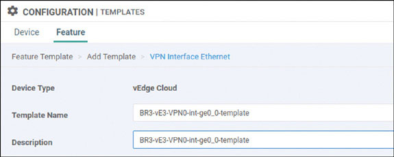
Select Basic Configuration, set Shutdown to No, and enter the interface name ge0/0. Then provide the static IP address 192.11.33.123/24 for this interface, as shown on the next page:
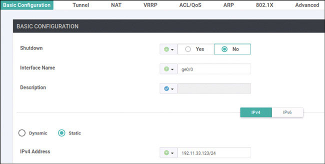
Select Tunnel, set Tunnel Interface to On, and select biz-internet from the Color dropdown, as shown below:
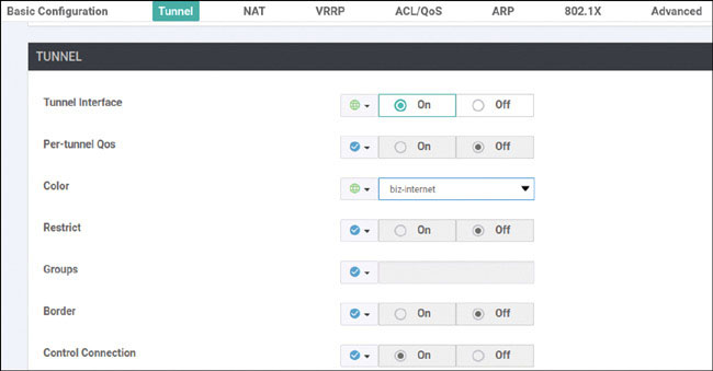
Scroll down to the Allow Service section and set All to On, as shown below:
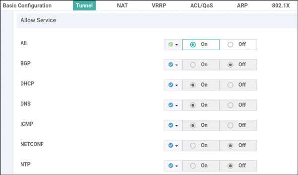
Click Save.
Click Add Template. In the screen that appears, scroll down and select vEdge Cloud in the left-hand working pane. Then click VPN Interface Ethernet in the Select Template > VPN section in the right-hand working pane, as shown below:
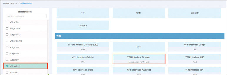
Name the template as shown below:
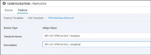
Select Basic Configuration, set Shutdown to No, and enter the interface name ge0/1. Then provide the static IP address 192.12.33.123/24 for this interface, as shown below:
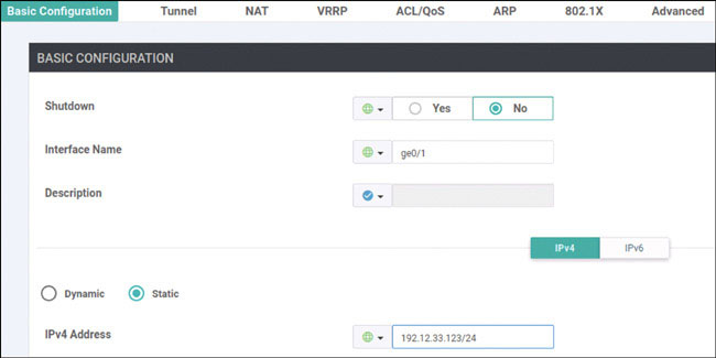
Select Tunnel, set Tunnel Interface to On, and select mpls from the Color dropdown, as shown below:
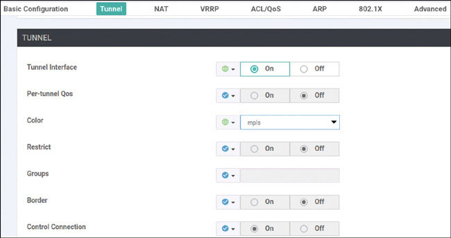
Scroll down to the Allow Service section and set All to On, as shown below:
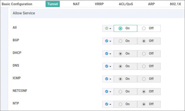
Click Save.
Click Add Template. In the screen that appears, scroll down and select vEdge Cloud in the left-hand working pane. Then click VPN in the Select Template > VPN section in the right-hand working pane, as shown below:
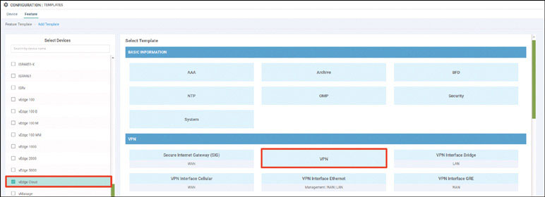
Name the template as shown below:
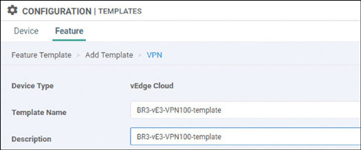
Select Basic Configuration and provide the VPN ID 100:
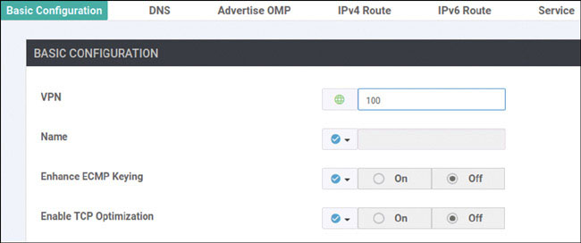
Click Save.
Click Add Template. In the screen that appears, scroll down and select vEdge Cloud in the left-hand working pane. Then click VPN Interface Ethernet in the Select Template > VPN section in the right-hand working pane, as shown below:
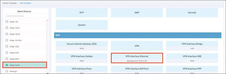
Name the template as shown below:
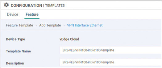
Select Basic Configuration, set Shutdown to No, and enter the interface name loopback100. Then provide the static IP address 10.3.100.123/24 for this interface, as shown below:
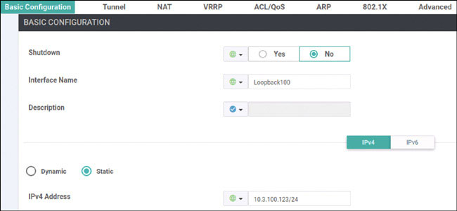
Click Save.
Click Add Template. In the screen that appears, scroll down and select vEdge Cloud in the left-hand working pane. Then click VPN in the Select Template > VPN section in the right-hand working pane, as shown below:
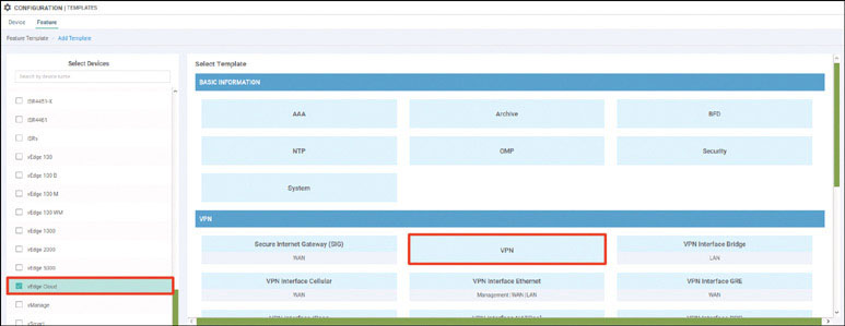
Name the template as shown below:
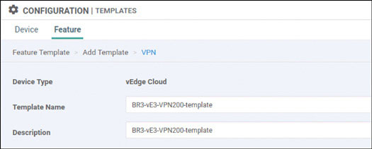
Select Basic Configuration and provide the VPN ID 200:

Click Save.
Click Add Template. In the screen that appears, scroll down and select vEdge Cloud in the left-hand working pane. Then click VPN Interface Ethernet in the Select Template > VPN section in the right-hand working pane, as shown below:
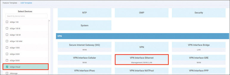
Name the template as shown below:
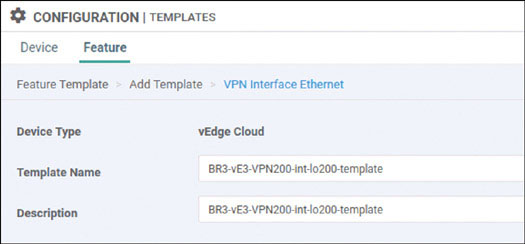
Select Basic Configuration, set Shutdown to No, and enter the interface name loopback200. Then provide the static IP address 10.3.200.123/24 for this interface, as shown below:
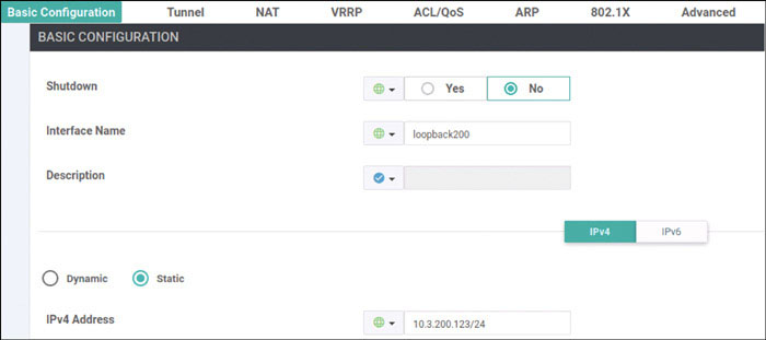
Click Save.
Click Add Template. In the screen that appears, scroll down and select vEdge Cloud in the left-hand working pane. Then click VPN in the Select Template > VPN section in the right-hand working pane, as shown below:
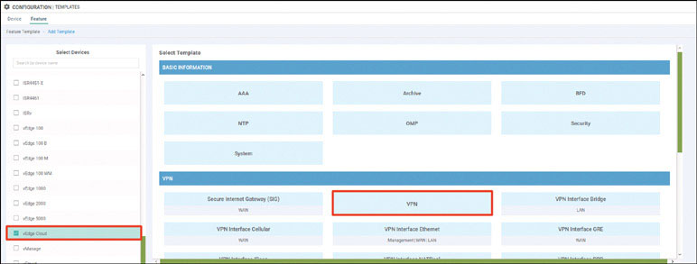
Name the template as shown below:
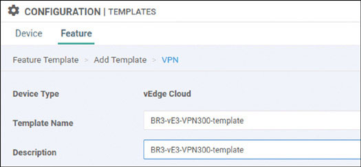
Select Basic Configuration and provide the VPN ID 300:

Click Save.
Click Add Template. In the screen that appears, scroll down and select vEdge Cloud in the left-hand working pane. Then click VPN Interface Ethernet in the Select Template > VPN section in the right-hand working pane, as shown below:
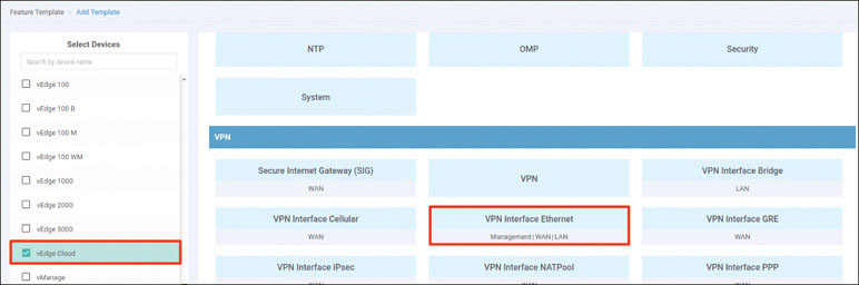
Name the template as shown below:
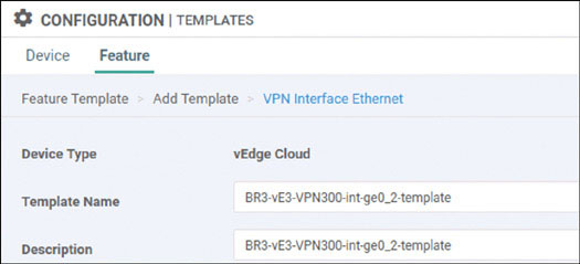
Select Basic Configuration, set Shutdown to No, and enter the interface name ge0/2. Then provide the static IP address 10.2.11.123/24 for this interface, as shown below:
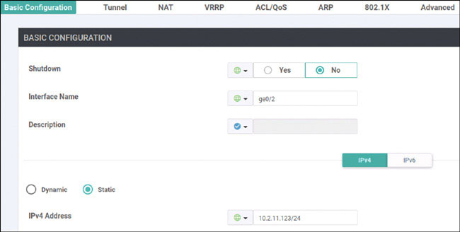
Click Save.
Click Add Template. In the screen that appears, scroll down and select vEdge Cloud in the left-hand working pane. Then click VPN in the Select Template > VPN section in the right-hand working pane, as shown below:
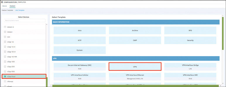
Name the template as shown below:
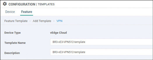
Select Basic Configuration and provide the VPN ID 512:
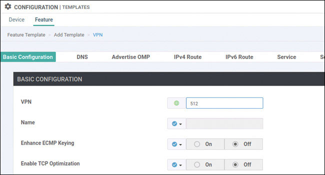
Click Save.
Click Add Template. In the screen that appears, scroll down and select vEdge Cloud in the left-hand working pane. Then click VPN Interface Ethernet in the Select Template > VPN section in the right-hand working pane, as shown below:
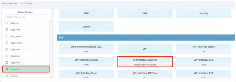
Name the template as shown below:
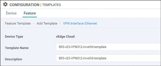
Select Basic Configuration, set Shutdown to No, and enter the interface name eth0. Then provide the static IP address 10.82.83.123/24 for this interface, as shown below:
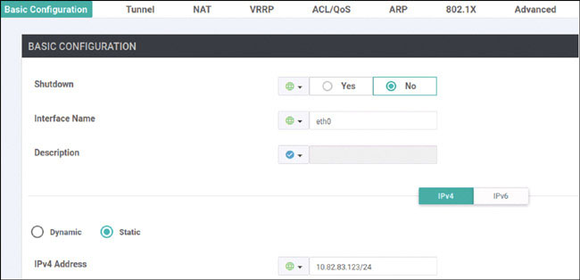
Click Save.
Navigate to Configuration > Templates > Device > Create Template and select From Feature Template. Select vEdge Cloud from the Device Model dropdown and name the template as shown below:
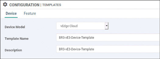
Select Basic Information and make the changes shown below:
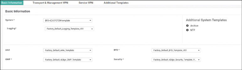
Select Transport & Management VPN and make the changes shown below:
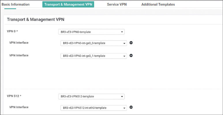
Select Service VPN and click Add VPN:
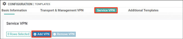
In the Available VPN Templates pane, select BR3-vE3-VPN100-template and click the right-pointing arrow to move selected template to the right-hand working pane:
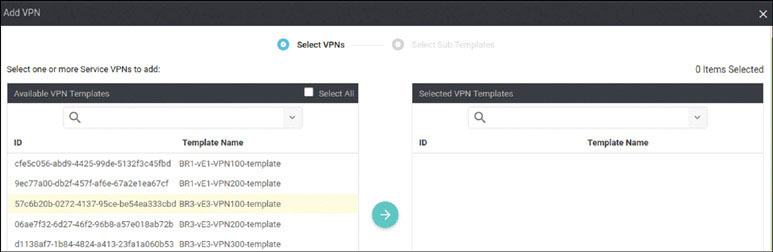
Click Next.
Modify the Add VPN window as shown below:
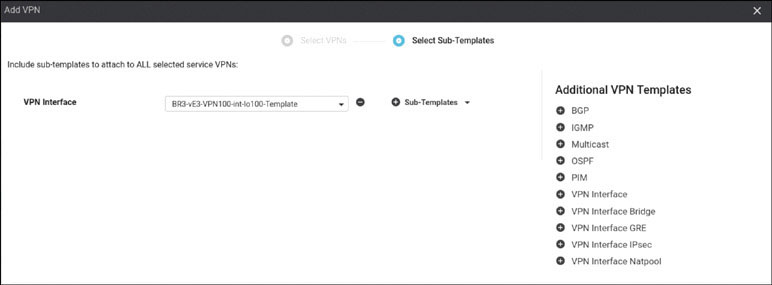
Click Add.
Click Add VPN again:
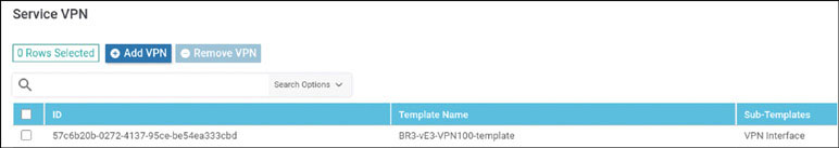
In the Available VPN Templates pane, select BR3-vE3-VPN200-template and click the right-pointing arrow to move selected template to the right-hand working pane:
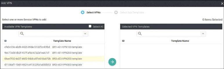
Modify the Add VPN window as shown below:
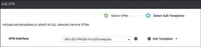
Click Add.
Click Add VPN again:
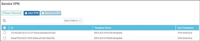
In the Available VPN Templates pane, select BR3-vE3-VPN300-template and click the right-pointing arrow to move selected template to the right-hand working pane:
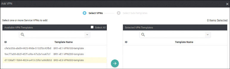
Modify the Add VPN window as shown below:
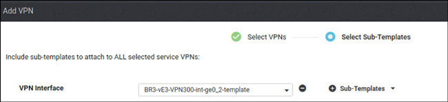
Click Add.
To complete the device template, click Create.
Attach this template to BR3-vE3 by clicking the … icon at the right of the following line and selecting Attach Devices, as shown below:
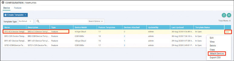
In the Attach Devices window select 1a11d205-0 in the Available Devices pane and click the right-pointing arrow to move the device to the Selected Devices pane. Then click Attach:
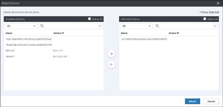
You now see the device template listed on the next screen. You should see that there is no green circle with a check mark at the far-left side of the screen. To correct this, click the … icon and then click Edit Device Template:
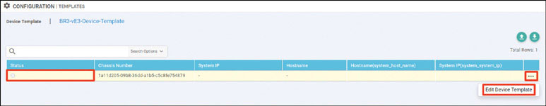
Fill in the Update Device Template window as shown below and then click Update:
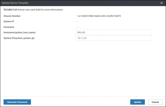
You should now see the screen shown below. If you do, click Next.

In the list of devices, select the chassis number shown on the next page and verify the configuration that will be pushed to the device. When you are satisfied with the configuration, click Configure Devices.
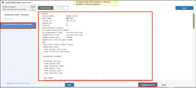
After a few moments, you should see the following:
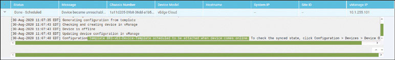
This is not what you have seen before when onboarding WAN edge devices. You see something different now because there is currently no configuration on BR3-vE3, and you have opted to deploy Branch-3 using Zero Touch Provisioning (ZTP). You have lots of work to do to get this device to attach to this device template that you just created.
You will need to make some modifications to your INET infrastructure. You know that for BR3-vE3 to communicate to any resource in the SEN fabric, it needs an IP address. You can use DHCP on ISP-1 to support this operation.
Creating a DHCP Server on ISP-1
Next, you need to access BR3-vE3 and look at its factory default configuration. First, you can look at VPN 0:
viptela 20.1.1

vedge login: admin
Password: admin
Welcome to Viptela CLI
admin connected from 127.0.0.1 using console on vedge
You must set an initial admin password.
Password: admin
Re-enter password: admin

vedge# show running-config vpn 0 interface ge0/0
vpn 0
 interface ge0/0
  ip dhcp-client
  ipv6 dhcp-client
  tunnel-interface
   encapsulation ipsec
   no allow-service bgp
   allow-service dhcp
   allow-service dns
   allow-service icmp
   no allow-service sshd
   no allow-service netconf
   no allow-service ntp
   no allow-service ospf
   no allow-service stun
   allow-service https
  !
  no shutdown
 !
!
vedge#
You can see that interface ge0/0 is (from the factory) configured for DHCP support and that it is part of VPN 0 by default. You can leverage this to your advantage.
Next, you need to perform a basic DHCP configuration on ISP-1, as shown below:
ISP-1>en
ISP-1# conf t
Enter configuration commands, one per line.  End with CNTL/Z.
ISP-1(config)# ip dhcp excluded-address 192.11.33.1 192.11.33.200
ISP-1(config)# ip dhcp pool ZTP-OPERATIONS
ISP-1(dhcp-config)# network 192.11.33.0 /24
ISP-1(dhcp-config)# default-router 192.11.33.113
You should see that an IP address was issued to BR3-vE3:
ISP-1# show ip dhcp binding
Bindings from all pools not associated with VRF:
IP address          Client-ID/     Lease expiration        T
ype
    Hardware address/
    User name
192.11.33.201       0150.0000.0e00.01       Aug 31 2020 10:20 AM    A
utomatic
ISP-1#
You can also verify this on BR3-vE3, as shown below:
vedge# show interface description

                                        IF      IF      IF
                AF                      ADMIN   OPER    TRACKER
VPN  INTERFACE  TYPE  IP ADDRESS        STATUS  STATUS  STATUS   DESC
----------------------------------------------------------------------
0    ge0/0      ipv4  192.11.33.201/24  Up      Up      NA       -
0    ge0/1      ipv4  -                 Down    Down    NA       -
0    ge0/2      ipv4  -                 Down    Down    NA       -
0    ge0/3      ipv4  -                 Down    Down    NA       -
512  eth0       ipv4  -                 Up      Up      NA       -

vedge#
As a result of this configuration, BR3-vE3 now has reachability into the infrastructure. You can validate this as shown below:
vedge# ping 192.1.255.101 count 5 ← vManage
Ping in VPN 0
PING 192.1.255.101 (192.1.255.101) 56(84) bytes of data.
64 bytes from 192.1.255.101: icmp_seq=1 ttl=62 time=1.16 ms
64 bytes from 192.1.255.101: icmp_seq=2 ttl=62 time=0.902 ms
64 bytes from 192.1.255.101: icmp_seq=3 ttl=62 time=1.01 ms
64 bytes from 192.1.255.101: icmp_seq=4 ttl=62 time=0.647 ms
64 bytes from 192.1.255.101: icmp_seq=5 ttl=62 time=0.516 ms

--- 192.1.255.101 ping statistics ---
5 packets transmitted, 5 received, 0% packet loss, time 4002ms
rtt min/avg/max/mdev = 0.516/0.847/1.162/0.238 ms
vedge#

vedge# ping 192.1.255.102 count 5 ← vBond
Ping in VPN 0
PING 192.1.255.102 (192.1.255.102) 56(84) bytes of data.
64 bytes from 192.1.255.102: icmp_seq=1 ttl=62 time=30.4 ms
64 bytes from 192.1.255.102: icmp_seq=2 ttl=62 time=30.7 ms
64 bytes from 192.1.255.102: icmp_seq=3 ttl=62 time=30.4 ms
64 bytes from 192.1.255.102: icmp_seq=4 ttl=62 time=29.4 ms
64 bytes from 192.1.255.102: icmp_seq=5 ttl=62 time=22.4 ms

--- 192.1.255.102 ping statistics ---
5 packets transmitted, 5 received, 0% packet loss, time 4002ms
rtt min/avg/max/mdev = 22.417/28.701/30.723/3.173 ms
vedge#


vedge# ping 192.1.255.103 count 5 ← vSmart
Ping in VPN 0
PING 192.1.255.103 (192.1.255.103) 56(84) bytes of data.
64 bytes from 192.1.255.103: icmp_seq=1 ttl=62 time=1.03 ms
64 bytes from 192.1.255.103: icmp_seq=2 ttl=62 time=0.747 ms
64 bytes from 192.1.255.103: icmp_seq=3 ttl=62 time=0.666 ms
64 bytes from 192.1.255.103: icmp_seq=4 ttl=62 time=0.604 ms
64 bytes from 192.1.255.103: icmp_seq=5 ttl=62 time=0.566 ms

--- 192.1.255.103 ping statistics ---
5 packets transmitted, 5 received, 0% packet loss, time 3999ms
rtt min/avg/max/mdev = 0.566/0.724/1.037/0.168 ms
vedge#
Now you have the reachability issue out of the way, but there is another issue. Note that when you run the show run system command, as shown below, you see that the device is using ztp.viptela.com as the identity of the vBond device:
vedge# show running-config system
system
 host-name               vedge
 admin-tech-on-failure
 no route-consistency-check
 vbond ztp.viptela.com
 aaa
  auth-order local radius tacacs
  usergroup basic
   task system read write
   task interface read write
  !
<output omitted for brevity>

vedge# ping ztp.viptela.com
Ping in VPN 0
ping: ztp.viptela.com: Temporary failure in name resolution
vedge#
This is because ZTP configuration works like PNP configuration. The device connects and authenticates to Viptela’s ZTP server, and if it is whitelisted, it is redirected to the organizational vBond controller. You need to provide a DNS solution to facilitate this lookup and at the same time redirect that request to your internal ZTP server.
To accomplish this, use the following syntax:
ISP-1(config)# ip host ztp.viptela.com 192.1.20.141
ISP-1(config)# ip dns server

ISP-1(config)# ip domain lookup
ISP-1(config)# ip dhcp pool ZTP-OPERATIONS
ISP-1(dhcp-config)# dom
ISP-1(dhcp-config)# dns-server 192.11.33.113
ISP-1(dhcp-config)# int e0/0
ISP-1(config-if)# shut
ISP-1(config-if)# no shut
ISP-1(config-if)#
Now you want to see if BR3-vE3 will resolve the IP address 192.11.20.141 for ztp.viptela.com. You have not configured the ZTP server yet, so a ping should fail. But you can use the command shown below to see if it resolves:
vedge# ping ztp.viptela.com
Ping in VPN 0
PING ztp.viptela.com (192.1.20.141) 56(84) bytes of data.
You can see that BR3-vE3 resolves the IP address. Now you can make the basic configuration on the ZTP server for reachability:
viptela 20.1.1

vedge login: admin
Password:
Welcome to Viptela CLI
admin connected from 127.0.0.1 using console on vedge
You must set an initial admin password.
Password: admin
Re-enter password: admin
vedge# config
Entering configuration mode terminal
vedge(config)# vpn 0
vedge(config-vpn-0)# interface ge0/0
vedge(config-interface-ge0/0)# ip address 192.1.20.141/24
vedge(config-interface-ge0/0)# no shut
vedge(config-interface-ge0/0)# exit
vedge(config-vpn-0)# ip route 0.0.0.0/0 192.1.20.115
vedge(config-vpn-0)# commit
Commit complete.
When you use the command shown below, you should see that BR3-vE3 has reachability to the ZTP server:
vedge# ping ztp.viptela.com
Ping in VPN 0
PING ztp.viptela.com (192.1.20.141) 56(84) bytes of data.

From ztp.viptela.com (192.1.20.141) icmp_seq=332 Destination Net
Unreachable
64 bytes from ztp.viptela.com (192.1.20.141): icmp_seq=337 ttl=62
time=1.39 ms
64 bytes from ztp.viptela.com (192.1.20.141): icmp_seq=338 ttl=62
time=0.681 ms
64 bytes from ztp.viptela.com (192.1.20.141): icmp_seq=339 ttl=62
time=0.591 ms
64 bytes from ztp.viptela.com (192.1.20.141): icmp_seq=340 ttl=62
time=0.598 ms
64 bytes from ztp.viptela.com (192.1.20.141): icmp_seq=341 ttl=62
time=0.634 ms
64 bytes from ztp.viptela.com (192.1.20.141): icmp_seq=342 ttl=62
time=1.14 ms
<control-c>
The next step is to get the ZTP server configured and to get a certificate signed for it. Because you are using self-signed certificates, you need to manually complete this process. The easiest way to accomplish this is to add the ZTP server to the vManage UI, sign its certificate, and then decommission the device. To do this, you need to apply the appropriate configuration to the ZTP server:
vedge(config)# system
vedge(config-system)# host-name ZTP-Server
vedge(config-system)# system-ip 10.1.1.141
vedge(config-system)# site-id 255
vedge(config-system)# organization-name micronicslab.com
vedge(config-system)# vbond 192.1.20.141 local ztp-server
vedge(config-system)# commit
Commit complete.
Download ROOTCA.pem and install it as you did for the previous controllers:
ZTP-Server(config-system)# exit
ZTP-Server(config)# vpn 0
ZTP-Server(config-vpn-0)# interface ge0/0
ZTP-Server(config-interface-ge0/0)# no tunnel-interface
ZTP-Server(config-interface-ge0/0)# commit
Commit complete.
ZTP-Server(config-interface-ge0/0)# end
ZTP-Server# vshell
ZTP-Server:~$ scp [email protected]:/home/user/Downloads/ROOTCA.pem
.
The authenticity of host '192.1.255.100 (192.1.255.100)' can't be est
ablished.
ECDSA key fingerprint is SHA256:Zz7IDU5Bkxvuh2GiVVWx8C9+OKr0U8ZC99BQe
icDmCc.
Are you sure you want to continue connecting (yes/no)? yes

Warning: Permanently added '192.1.255.100' (ECDSA) to the list of kno
wn hosts.
[email protected]'s password: Test123
ROOTCA.pem                                      0%    0     0.0KB/s
ROOTCA.pem                                    100% 1521    24.7KB/s
 00:00
ZTP-Server:~$ exit
exit
ZTP-Server# request root-cert-chain install /home/admin/ROOTCA.pem
Uploading root-ca-cert-chain via VPN 0
Copying ... /home/admin/ROOTCA.pem via VPN 0
Updating the root certificate chain..
Successfully installed the root certificate chain
ZTP-Server#
Now you can verify that the root certificate was installed, as shown below:
ZTP-Server# show control local-properties
personality                       vedge
sp-organization-name              micronicslab.com
organization-name                 micronicslab.com
root-ca-chain-status              Installed

certificate-status                Not-Installed
<output omitted for brevity>
To onboard the ZTP server, in the vManage UI, navigate to Configuration > Devices > Controllers > Add Controller > vBond. In the Add vBond screen, provide the information shown below. Ensure that the Generate CSR checkbox is not checked and click Add.
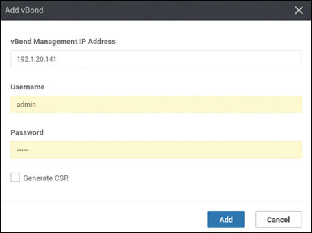
Navigate to Configuration > Certificates > Controllers and then find the vBond controller that says No certificate installed, click the … icon to the right of that controller, and select Generate CSR, as shown below:
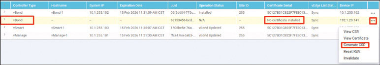
On the CSR screen, click Download:
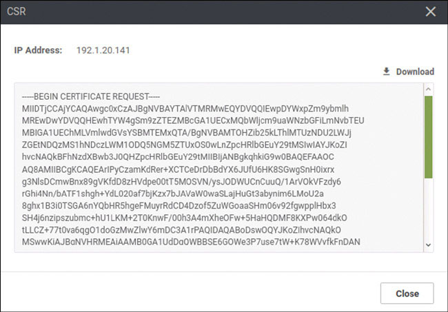
Save undefined.csr to your Downloads folder, as shown below:
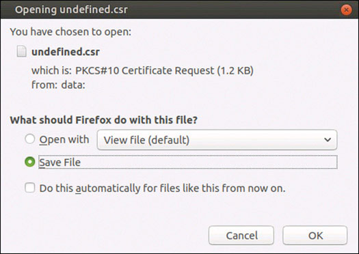
In a terminal session, change the name undefined.csr to ztp-server.csr. Then sign it as shown below:
user@user-pc:~/Downloads$ mv undefined.csr ztp-server.csr
user@user-pc:~/Downloads$ openssl x509 -req -in ztp-server.csr -CA
ROOTCA.pem -CAkey ROOTCA.key -CAcreateserial -out ztp-server.crt -days
2000 -sha256
Signature ok
subject=C = US, ST = California, L = San Jose, OU = micronicslab.com,
O = Viptela LLC, CN = vbond-8e153456-bcda-4431-a473-c58494c9e519-1.
viptela.com, emailAddress = [email protected]
Getting CA Private Key
Print the contents of ztp-server.crt and copy it into the vManage UI dashboard:
user@user-pc:~/Downloads$ cat ztp-server.crt
-----BEGIN CERTIFICATE-----
MIID+jCCAuICFBL3Y9wF3DXgSL18Rg4QhtKLK+tTMA0GCSqGSIb3DQEBCwUAMIGk
MQswCQYDVQQGEwJVUzELMAkGA1UECAwCVkExEDAOBgNVBAcMB1JhZGlhbnQxGTAX
BgNVBAoMEG1pY3Jvbmljc2xhYi5jb20xGTAXBgNVBAsMEG1pY3Jvbmljc2xhYi5j
b20xGTAXBgNVBAMMEG1pY3Jvbmljc2xhYi5jb20xJTAjBgkqhkiG9w0BCQEWFmFk
bWluQG1pY3Jvbmljc2xhYi5jb20wHhcNMjAwODMxMjE0MDA4WhcNMjYwMjIxMjE0
MDA4WjCBzTELMAkGA1UEBhMCVVMxEzARBgNVBAgTCkNhbGlmb3JuaWExETAPBgNV
BAcTCFNhbiBKb3NlMRkwFwYDVQQLExBtaWNyb25pY3NsYWIuY29tMRQwEgYDVQQK
EwtWaXB0ZWxhIExMQzFBMD8GA1UEAxM4dmJvbmQtOGUxNTM0NTYtYmNkYS00NDMx
LWE0NzMtYzU4NDk0YzllNTE5LTEudmlwdGVsYS5jb20xIjAgBgkqhkiG9w0BCQEW
E3N1cHBvcnRAdmlwdGVsYS5jb20wggEiMA0GCSqGSIb3DQEBAQUAA4IBDwAwggEK
AoIBAQCsg/ILNqYp1F6v5cJMJ4OsNsF1hfolR9TocrxIbCBKcfSLGvGDc2WwMKbA
GfHz2BUp90PzMdV2l7TS1Pkw5JU3/Kwk4NZQKcK65D/UCtU6RUXN3LqsaGLg2f9s
BMXWyGCH5h0vTbRp/tuMrPHtskBVpbTBpItqMe4a3dpvKeKbosyhTZryCHHUHeLR
NIYDqdhBsdHmGB4Uy7KtF0IPgPOh/lm5YahppIebTq/3Z+DCmmUdvHdIfiPqfOKm
zO5uZz6FTUsoz7ZPQqfAX/TSHcDiZeF44XD7kdodAMwXwpc/DTrh2Q60ssJn7vu3
S9rqqA7V2gbMzBmXBjqYMLcDWs8BAgMBAAEwDQYJKoZIhvcNAQELBQADggEBAGYi
XlKDV0hXguvghA1JJ5t987oAgmVeyFk1QA5g4jVz8zzK63HOrdk8J76XtzBvfn6W
imaLggd7yOAPlhjY+rndJaAMKOvT56Ez0MCQmcua3b3MMrgR18mlly1JfLQEf0M/
pOIM8up52VPrfWBZ5gG1s+5Gr6rH9k4JIxFsWIuIPUOHCPOEwjuF15dU5kFlNxxU
DyP34CPgtyE3ZPA6Ek0mKECHm/WsxBQ0XYVmgnEq3cEomz8tbN8g0HVSRIDwxn5h
AtPdtk4I6rnIEabUVPUEb5+T/udVckEKy3fpq++MzlMFkp/0Vqmm5hVx7PM0CJlC
r7rK8bYmFn5wMEmDxPc=
-----END CERTIFICATE-----
user@user-pc:~/Downloads$
Click Install.
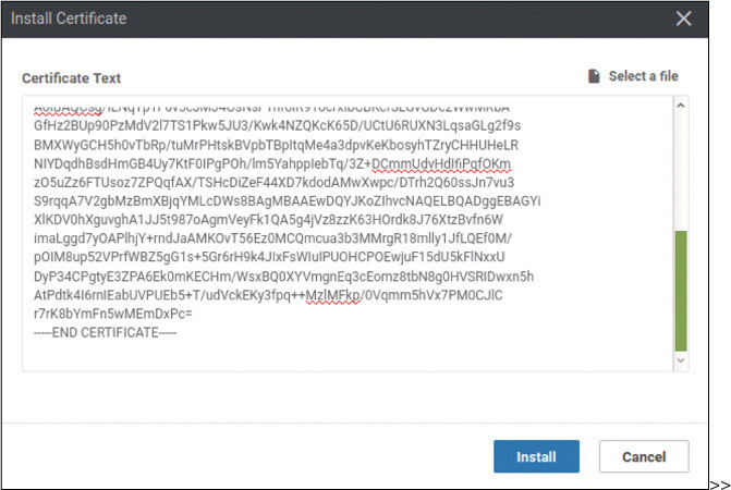
>>
When the process is complete, you should see the following:
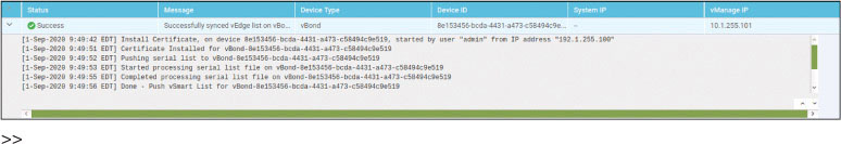
>>
Now you need to provide the necessary configuration on ztp-server to support the registration of the BR3-vE3 edge device. To do this, you need to enter the whitelist of valid chassis numbers that will be allowed to join the fabric. To keep this example simple, you will add just one device.
Open the console of the ZTP server and enter the following information:
ZTP-Server# request device add chassis-number 1a11d205-09b8-36dd-a1b5-
c5c8fe754879 serial-number df052bedd3cf3a951fd708ecc92b935e validity
 valid vbond 192.1.255.102 org-name micronicslab.com
Chassis number 10D118E8-9F83-14F3-5933-3A2891307BE5 successfully added
to the database

ZTP-Server# show ztp entries
ztp entries 1
 chassis-number  10D118E8-9F83-14F3-5933-3A2891307BE5 ← CN of the next
vedge
 serial-number   1AFD615E6B7752AB8DB10A30ACD7F8B8 ←OTP Token for that
vedge

 validity          valid
 vbond-ip          192.1.255.102 ← IP Address of our organizational
vBond
 vbond-port        12346
 organization-name micronicslab.com ← exact organizational name in our
labs
 root-cert-path    default
ZTP-Server#
Install the root-ca-certificate on BR3-vE3:
vedge# config
Entering configuration mode terminal
vedge(config)# vpn 0
vedge(config-vpn-0)# interface ge0/0
vedge(config-interface-ge0/0)# tunnel-interface
vedge(config-tunnel-interface)# encapsulation ipsec
vedge(config-tunnel-interface)# allow-service sshd
vedge(config-tunnel-interface)# commit and-quit
Commit complete.
vedge# vshell
vedge:~$ scp [email protected]:/home/user/Downloads/ROOTCA.pem .
The authenticity of host '192.1.255.100 (192.1.255.100)' can't be est
ablished.
ECDSA key fingerprint is SHA256:Zz7IDU5Bkxvuh2GiVVWx8C9+OKr0U8ZC99BQe
icDmCc.
Are you sure you want to continue connecting (yes/no)? yes
Warning: Permanently added '192.1.255.100' (ECDSA) to the list of kno
wn hosts.
[email protected]'s password: Test123
ROOTCA.pem                                      0%    0     0.0KB/s
ROOTCA.pem                                    100% 1505     1.0MB/s
 00:00
vedge:~$exit
exit
vedge# request root-cert-chain install /home/admin/ROOTCA.pem
Uploading root-ca-cert-chain via VPN 0
Copying ... /home/admin/ROOTCA.pem via VPN 0
Updating the root certificate chain..
Successfully installed the root certificate chain
vedge#
Request that the SEN fabric activate the chassis and token:
vedge# request vedge-cloud activate chassis-number 1a11d205-09b8-36dd-
a1b5-c5c8fe754879 token df052bedd3cf3a951fd708ecc92b935e
After a few moments, the vEdge device successfully joins the fabric.
To test this deployment to make sure everything works, you can enter the pings shown below on Docker23 to see if you can reach the VPN 200 resources at Branch-3:
root@Docker23:~# ping 10.3.200.123 -c 5
PING 10.3.200.123 (10.3.200.123) 56(84) bytes of data.
64 bytes from 10.3.200.123: icmp_seq=1 ttl=63 time=0.932 ms
64 bytes from 10.3.200.123: icmp_seq=2 ttl=63 time=1.16 ms
64 bytes from 10.3.200.123: icmp_seq=3 ttl=63 time=1.25 ms
64 bytes from 10.3.200.123: icmp_seq=4 ttl=63 time=0.827 ms
64 bytes from 10.3.200.123: icmp_seq=5 ttl=63 time=0.917 ms

--- 10.3.200.123 ping statistics ---
5 packets transmitted, 5 received, 0% packet loss, time 4015ms
rtt min/avg/max/mdev = 0.827/1.019/1.253/0.164 ms
Test reachability in VRF/VPN 100 from RM-R1:
RM-R1# ping 10.3.100.123
Type escape sequence to abort.
Sending 5, 100-byte ICMP Echos to 10.3.100.123, timeout is 2 seconds:
!!!!!
Success rate is 100 percent (5/5), round-trip min/avg/max = 1/1/2 ms
RM-R1#
You can see that all reachability has been resolved in Branch-1.
Lab 8: Configuring an Application-Aware Routing Policy
Open vManage in another tab to create the policy.
Select Configuration > Policies, as shown below:
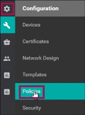
click Add Policy:
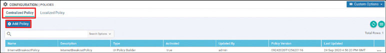
Click SLA Class as shown below:
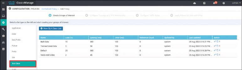
Click New SLA Class List:
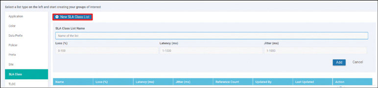
Set SLA Class List Name to SLA, set Latency to 100, and click Add.
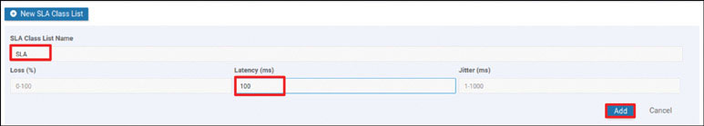
Click Next.
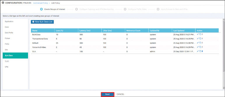
Click Next again.
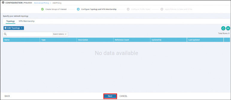
Under Application Aware Routing, click Add Policy and select Create New, as shown below:
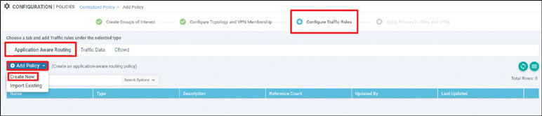
Configure both Name and Description as AAR:
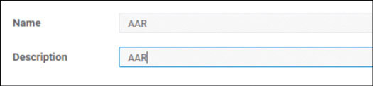
Click Sequence Type and click Sequence Rule to create a new rule:
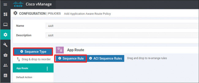
Select Source Data Prefix, use the IP prefix 10.0.0.0/8, click DSCP, and set DSCP to 46, as shown below:
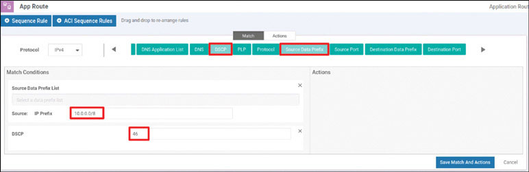
Under Actions, click SLA Class List:
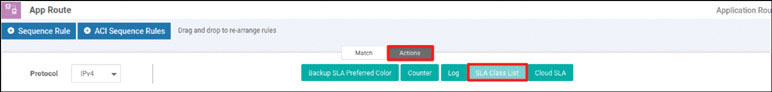
Choose SLA under SLA Class:
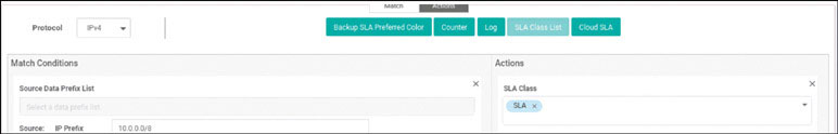
Set Preferred Color to mpls:
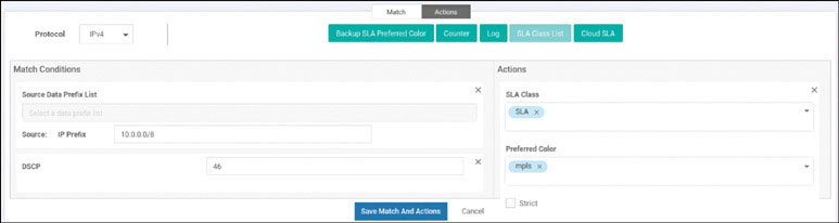
Click Backup SLA Preferred Color, as shown below:
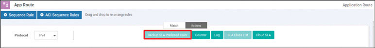
Set Backup SLA Preferred Color to biz-internet, as shown below:
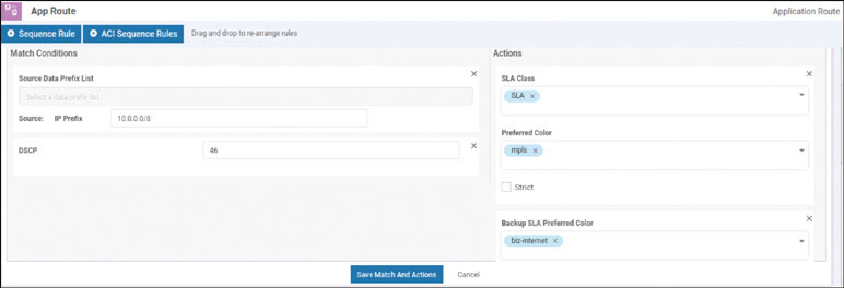
Click Save Match and Actions.
Save the policy by clicking Save Application Aware Routing Policy, as shown below:
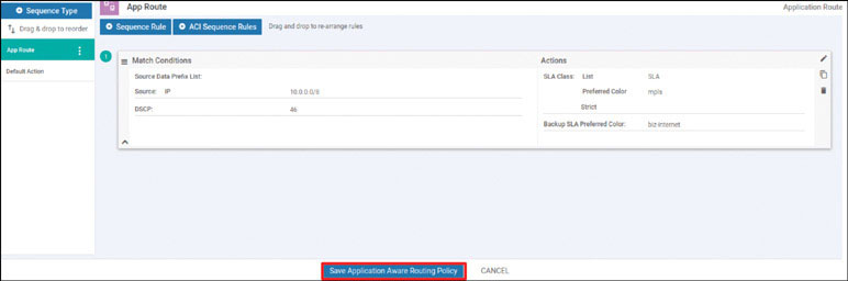
When you see that the AAR policy has been created, as shown below, click Next:
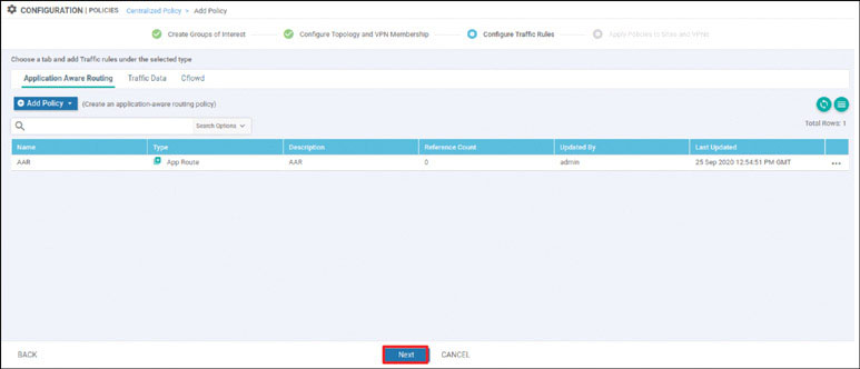
Under Apply Policies to Sites and VPNs, set Policy Name to Micronics-AAR-Policy and set Policy Description to Micronics-AAR-Policy, as shown below:
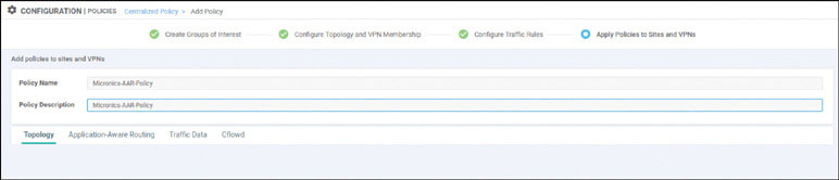
In the Application-Aware Routing section, click New Site List and VPN List:
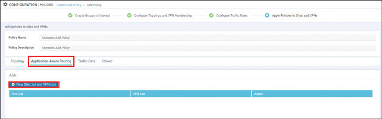
Select Branch-2:
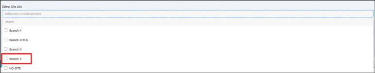
Select VPN100 and then click Add:
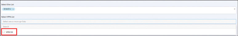
Save the policy by clicking Save Policy:
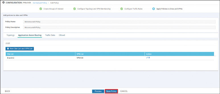
To view the policy, find Micronics-AAR-Policy, click the … icon to the right of it, and select Preview:
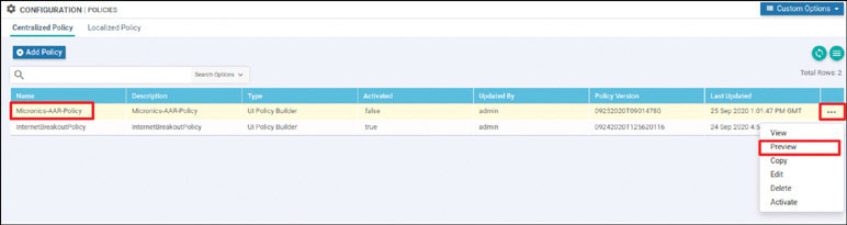
Your policy should look as shown below:
viptela-
  policy:policy
  sla-class SLA
   latency 100
 !
app-route-policy
 _VPN100_AAR vpn-list
 VPN100
   sequence
    1 match
     source-ip
     10.0.0.0/8 dscp
     46
     !
     action
      sla-class SLA preferred-color mpls
      backup-sla-preferred-color biz-
      internet
      !
     !
!
lists
 site-list
  Branch-2 site-
  id 2
 !
 vpn-list
  VPN100 vpn
  100
  !
 !
!

viptela-policy:apply-
 policy site-list
 Branch-2
  app-route-policy _VPN100_AAR
 !
!
To activate the policy, find Micronics-AAR-Policy, click the … icon to the right of it, and select Activate:
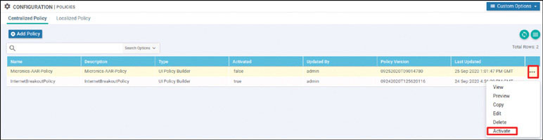
The policy is applied to vSmart. Click Activate:
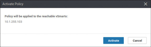
Wait until the policy push is successful.
You have now created and activated an AAR policy.