Chapter 5
OSPF
Lab 1: Running OSPF on the Interfaces

This lab should be conducted on the Enterprise POD.
Lab Setup:
If you are using EVE-NG, and you have imported the EVE-NG topology from the EVE-NG-Topology folder, ignore the following tasks and use Lab 1-Running OSPF on the Interfaces in the OSPF folder in EVE-NG.
To copy and paste the initial configurations, go to the Initial-config folder → OSPF folder → Lab-1.
Task 1
Configure OSPF Area 0 on all directly connected interfaces in the previous topology, including the secondary IP addresses.
Do not use the network command to accomplish this task.
The loopback interfaces should be advertised with their correct mask.
If this configuration is performed successfully, each router will have reachability to all routes within the previous topology.
The OSPF RID should be configured based on the Lo0 interface of these three routers.
Task 2
Configure R2 and R3 such that the secondary IP addresses are not advertised into OSPF.
Do not use filtering, a route map, an access list, or a prefix list.
Do not remove any commands.
Use a minimum number of commands to accomplish this task.
Task 3
R3 is getting flooded with LSA Type 6 packets. Ensure that R3 does not generate a syslog message for this LSA type.
Task 4
To ensure fast detection of a neighbor being down, configure R2 and R3 to send their hellos every 250 milliseconds with a hold time of 1 second for their Ethernet link.
Task 5
Ensure that these routers look up DNS names for use in most of the OSPF show commands. Test this task to ensure proper operation. Since there are no DNS servers in this lab, you should use the local routers for DNS lookups.
Task 6
Configure R2 such that if it does not receive an acknowledgment from R3 for a given LSA, it waits 10 seconds before it re-sends that given LSA.
Task 7
Configure R1 and R2 such that when there is a topology change in Area 0 for LSA Types 1 and 2, the entire SPT is not recomputed. This should only occur for the affected part/s of the tree.
Task 8
Erase the startup configuration and reload the routers before proceeding to the next lab.
Lab 2: OSPF Broadcast Networks

This lab should be conducted on the Enterprise POD.
Lab Setup:
If you are using EVE-NG, and you have imported the EVE-NG topology from the EVE-NG-Topology folder, ignore the following tasks and use Lab 2-OSPF Broadcast Network in the OSPF folder in EVE-NG.
To copy and paste the initial configurations, go to the Initial-config folder → OSPF folder→ Lab-2.
Task 1
Configure OSPF Area 0 on all routers and their directly connected interfaces. Ensure that Loopback0 interfaces are advertised with their correct mask. You should configure the OSPF router IDs to be 0.0.0.x, where x is the router number.
Task 2
Lab Setup:
Erase the configuration of all routers and SW1. To copy and paste the initial configurations, go to the Initial-config folder → OSPF folder→ Lab-2-Task-2.

Configure OSPF on the tunnel and Loopback0 interfaces of all routers, based on the following policy:
R1 is the hub, and R2, R3, and R4 are configured as spokes. Do not change the topology.
Configure the tunnel interfaces of all routers to be OSPF broadcast network type.
The loopback interfaces should be advertised with their correct mask.
Configure the router IDs of R1, R2, R3, and R4 to be 0.0.0.1, 0.0.0.2, 0.0.0.3, and 0.0.0.4, respectively.
You should use static maps on the DMVPN network.
Spokes should traverse the hub to reach all networks.
Task 3
Erase the startup configuration of the routers, the config.text file, and the VLAN.dat file of each switch and reload the devices before proceeding to the next lab.
Lab 3: OSPF Non-broadcast Networks
This lab should be conducted on the Enterprise POD.
Lab Setup:
If you are using EVE-NG, and you have imported the EVE-NG topology from the EVE-NG-Topology folder, ignore the following tasks and use Lab 3-OSPF Non-Broadcast Networks in the OSPF folder in EVE-NG.
To copy and paste the initial configurations, go to the Initial-config folder → OSPF folder→ Lab-3.
Task 1
Configure OSPF Area 0 on all routers and their directly connected interfaces. You should configure the tunnel interfaces as the OSPF non-broadcast network type. Configure the OSPF router IDs to be 0.0.0.x, where x is the router number.
Task 2
Erase the startup configuration of the routers, the config.text file, and the VLAN.dat file of each switch and reload the devices before proceeding to the next lab.
Lab 4: OSPF Point-to-Point Networks

This lab should be conducted on the Enterprise POD.
Lab Setup:
If you are using EVE-NG, and you have imported the EVE-NG topology from the EVE-NG-Topology folder, ignore the following tasks and use Lab 4-OSPF Point-to-Point Networks in the OSPF folder in EVE-NG.
To copy and paste the initial configurations, go to the Initial-config folder → OSPF folder→ Lab-4.
Task 1
Configure OSPF on all routers and run their directly connected interfaces in Area 0, based on the following policy:
The Loopback0 interfaces of these routers should be advertised with their correct mask.
Use 0.0.0.1, 0.0.0.2, and 0.0.0.3 as the router IDs of R1, R2, and R3, respectively.
There should not be any DR/BDR election on any of the links.
Do not configure point-to-multipoint or point-to-multipoint non-broadcast on any of the links.
Task 2
Erase the startup configuration of the routers, the config.text file, and the VLAN.dat file of each switch and reload the devices before proceeding to the next lab.
Lab 5: OSPF Point-to-Multipoint and Point-to-Multipoint Non-broadcast Networks

This lab should be conducted on the Enterprise POD.
Lab Setup:
If you are using EVE-NG, and you have imported the EVE-NG topology from the EVE-NG-Topology folder, ignore the following tasks and use Lab 5-OSPF Point-to-Multipoint & Point-to-Multipoint Non-broadcast Networks in the OSPF folder in EVE-NG.
To copy and paste the initial configurations, go to the Initial-config folder → OSPF folder→ Lab-5.
Task 1
Configure OSPF Area 0 on all links in the previous topology. The OSPF router IDs of all routers should be 0.0.0.x, where x is the router number. If this configuration is performed successfully, the routers in this topology should have full NLRI to every network in this topology. The tunnel interface of these routers should not perform DR/BDR election.
Task 2
Since R2’s connection to the cloud is 10 Mbps and R3’s connection is 100 Mbps, R1 should not perform equal-cost load sharing. R1 should go through R3 to reach network 23.1.1.0/24. Do not configure PBR or the IP ospf cost command to accomplish this task.
Task 3
Erase the startup configuration of the routers, the config.text file, and the VLAN.dat file of each switch and reload the devices before proceeding to the next lab.
Lab 6: OSPF Area Types

This lab should be conducted on the Enterprise POD.
Lab Setup:
If you are using EVE-NG, and you have imported the EVE-NG topology from the EVE-NG-Topology folder, ignore the following tasks and use Lab 6-OSPF Area Types in the OSPF folder in EVE-NG.
To copy and paste the initial configurations, go to the Initial-config folder → OSPF folder→ Lab-6.
Lab rules:
All loopback interfaces are configured with ip ospf network point-to-point.
Configure the OSPF router IDs of the routers based on the following chart:
R1: 0.0.0.1 | R2: 0.0.0.2 | R3: 0.0.0.3 |
R4: 0.0.0.4 | R5: 0.0.0.5 | R6: 0.0.0.6 |
R7: 0.0.0.7 | R8: 0.0.0.8 | SW1: 0.0.0.11 |
SW2: 0.0.0.22 | SW3: 0.0.0.33 | SW4: 0.0.0.44 |
SW5: 0.0.0.55 |
Task 1
Configure the Lo0 and G0/4 interfaces of R5 and G0/5 and the Lo0 interface of R4 in Area 1.
Task 2
Configure the G0/0 and Lo0 interfaces of R8 and the VLAN58 interface of SW5 in Area 2.
Task 3
Configure the following interfaces for OSPF Area 3:
E6/0 interface on SW4
E6/0, E5/0, and Loopback0 interfaces on SW3
E5/0 interface on SW5
Ensure that SW4 is configured to redistribute its Loopback0 through Loopback9 interfaces into this routing domain.
Task 4
Configure the following interfaces in Area 4:
R7’s G0/9 interface
SW2’s Lo0, E1/3, and E0/3 interfaces
R3’s G0/9 interface
Ensure that R7 is configured to redistribute the networks on its Loopback0 through Loopback9 interfaces into this routing domain.
Task 5
Configure the following interfaces in Area 5:
R6’s G0/0 interface
SW1’s Lo0, E1/2, and E0/2 interfaces
R2’s Loopback0 through Loopback2 and G0/0 interfaces
Ensure that R6 is configured to redistribute its Loopback0 through Loopback9 interfaces into this routing domain.
Task 6
Configure the following interfaces in Area 0:
R1’s Loopback0 through Loopback9, G0/0, G0/3, and G0/2 interfaces
R1 must be configured to redistribute its Lo10–Lo19 in this routing domain.
R4’s G0/0 interface
SW5’s VLAN145 and Loopback0 interfaces
R3’s G0/1 and Loopback 0 interfaces
R2’s G0/1 interface
Restrictions:
R4 should not use a network command to run its G0/0 interface in Area 0.
This router should not advertise any secondary IP address/es configured under its G0/0 interface.
Do not configure any kind of filtering to accomplish this task.
Task 7
Ensure that the routers in Area 1 do not have any OSPF external routes in their routing table; these routers should not have LSA Types 4 or 5 in their LSDB.
Task 8
Configure Area 2 such that existing and future external and inter-area routes are never seen in the routing tables of these routers. These routers should not have LSA Types 3, 4, or 5 in their LSDB, but these routers should have full reachability to the inter-area and external networks redistributed in this routing domain.
Restriction:
Do not use an ACL or a prefix list to accomplish this task.
Task 9
Configure the routers in Area 3 based on the following policy:
The routers must maintain existing and future inter-area routes in their routing tables.
The routers should not have LSA Types 4 or 5 in their OSPF link state database.
The routers should not have reachability to the routes redistributed in the other areas of this routing domain.
The routers should have reachability to the routes redistributed in their own area.
Task 10
Configure the routers in Area 4 based on the following policy:
The routers of this area should have LSA Type 3 in their OSPF link state database.
The routers of this area should not have LSA Types 4 or 5 in their OSPF link state database.
The routers must have reachability to the existing and future routes redistributed in the other areas of this routing domain, except for the external networks redistributed in Area 3.
The routers should have reachability to the networks redistributed in their own area.
Task 11
Implement the following policy for the routers in Area 5:
The routers must have reachability to the routes redistributed in this routing domain.
The routers should not maintain LSA Type 3 in the OSPF link state database.
The routers should not maintain LSA Types 4 or 5 in their OSPF link state database.
Task 12
Determine whether the routers in Area 0 maintain LSA Type 4 in their OSPF link state database.
Task 13
Configure R3 to redistribute its Lo1 interface such that existing and future redistributed routes by this router are only injected into Area 0 and not into Area 4. Do not configure an ACL or a prefix list to accomplish this task.
Task 14
Configure the following ABRs so that the default route that they inject has an OSPF cost based on the following table:
ABR/Area | OSPF Cost of the Injected Default Route |
|---|---|
R4/Area 1 | 40 |
R9/Area 2 | 133 |
R3/Area 4 | 30 |
R2/Area 5 | 20 |
Task 15
Erase the startup configuration of the routers, the config.text file, and the VLAN.dat file of each switch and reload the devices before proceeding to the next lab.
Lab 7: OSPF Filtering

This lab should be conducted on the Enterprise POD.
Lab Setup:
If you are using EVE-NG, and you have imported the EVE-NG topology from the EVE-NG-Topology folder, ignore the following tasks and use Lab 7-OSPF Filtering in the OSPF folder in EVE-NG.
To copy and paste the initial configurations, go to the Initial-config folder → OSPF folder→ Lab-7.
Pre-configuration:
OSPF is configured on all routers, and all loopback interfaces are configured with their correct masks.
OSPF router IDs are configured as 0.0.0.x, where x is the router number.
Task 1
Configure R1 and R3 such that the link connecting them to each other is not advertised into OSPF. R1 and R3 should still maintain their OSPF adjacency through this interface.
Task 2
Configure R5 such that it only advertises its Lo0 and Lo1 interface addresses into OSPF. Do not remove or modify the network command/s configured in the router configuration mode. You should use two different solutions: one for the Lo0 interface and a second one for the Lo1 interface.
Task 3
Configure R3 to redistribute all OSPF prefixes into BGP AS 100. R8 should redistribute its Lo88 into OSPF interfaces such that R7 filters network 88.0.0.0 /8 from getting into its BGP table.
Task 4
Configure LSA Type 3 filtering on R3 to filter network 1.1.1.0 /24 from the rest of the OSPF domain. You should reference Area 1 when accomplishing this task.
Task 5
Configure LSA Type 3 filtering on R8 to filter network 5.5.5.0 /24 from getting into Area 2.
Task 6
Configure LSA Type 3 filtering on R8 to filter network 50.5.5.0 /24. You should reference Area 0 when accomplishing this task.
Task 7
Configure R8 such that network 100.1.1.0 /24 is not advertised to the routers in Area 2. Do not use the following to accomplish this task:
A distribute list, an area filter list, distance, a route map, an access list, or a prefix list
Task 8
Configure R3 such that network 111.1.1.0 /24 is not advertised to routers in Area 0 or Area 2. Do not add any static routes, use a filter list, or use a distribute list to accomplish this task.
Task 9
Enable OSPF Area 2 on the G0/9 interfaces of R2, R4, and R6.
Task 10
Configure R2, R4, and R6 based on the following policy:
R2 should redistribute networks 120.2.2.0 /24 and 122.2.2.0 /24 as OSPF external Type 1 networks.
R2 should redistribute its Lo0 and Lo1 interfaces into the OSPF routing domain.
R4 should redistribute networks 140.4.4.0 /24 and 144.4.4.0 /24 as OSPF external Type 1 networks.
R4 should redistribute its Lo0 and Lo1 interfaces into the OSPF routing domain.
Task 11
Configure R2 and R6 to redistribute their Lo0 interfaces. Configure the appropriate routers such that the routers in Area 2 can see networks 2.2.2.0 /24, 4.4.4.0 /24, and 6.6.6.0 /24 in their routing tables. The routers in the other areas, however, should not have these networks in their routing table.
Task 12
Configure R2 to filter network 122.2.2.0 /24. The other routers should not have this route in their routing table or database.
Do not use summary-address to accomplish this task.
Do not modify the redistribution parameters to accomplish this task.
Task 13
Configure R2 to filter existing and future inter-area and/or intra-area routes from its routing table. Use the smallest number of commands possible to accomplish this task.
Task 14
Configure R4 to filter existing and future routes that have an OSPF cost of 20 from its routing table.
Task 15
Configure R6 to filter the default route injected by the ABR by R8 from its routing table.
Task 16
Configure R5 to filter network 1.1.1.0 /24. Do not use distribute-list to accomplish this task.
Task 17
Configure R1 to filter existing and future external routes. Do not configure an access list, a route map, or a prefix list to accomplish this task.
Task 18
Configure R7 to filter existing and future intra-area routes. Do not configure a route map, an access list, or a prefix list to accomplish this task.
Task 19
Configure R5 to filter existing and future intra-area routes. Do not configure a route map, an access list, or a prefix list to accomplish this task.
Task 20
Erase the startup configuration of the routers, the config.text file, and the VLAN.dat file of each switch and reload the devices before proceeding to the next lab.
Lab 8: OSPF Summarization

This lab should be conducted on the Enterprise POD.
Lab Setup:
If you are using EVE-NG, and you have imported the EVE-NG topology from the EVE-NG-Topology folder, ignore the following tasks and use Lab 8-OSPF Summarization in the OSPF folder in EVE-NG.
To copy and paste the initial configurations, go to the Initial-config folder → OSPF folder→ Lab-8.
Task 1
Configure the routers as follows:
R4 should redistribute the four loopback interfaces (4.4.0.4 /24–4.4.3.4 /24) into the OSPF routing domain.
R4 should advertise its Loopback4 and G0/3 interfaces in Area 2.
R1 should advertise all of its interfaces in OSPF Area 1. Use a minimum number of commands to accomplish this.
R2 should advertise its Loopback0 and G0/3 interfaces in Area 0. It should advertise its G0/1 interface in Area 1.
R3 should advertise its Loopback0 and G0/2 interfaces in Area 0. It should advertise its G0/4 interface in Area 2.
R1 should use 0.0.0.1, R2 should use 0.0.0.2, R3 should use 0.0.0.3, and R4 should use 0.0.0.4 as their OSPF router IDs.
Task 2
Configure the appropriate router in Area 2 to summarize all external (E2) routes.
Task 3
Configure the appropriate router in Area 1 to summarize the following four networks and only advertise a single summary route:
1.1.0.0 /24
1.1.1.0 /24
1.1.2.0 /24
1.1.3.0 /24
Task 4
Ensure that the routers do not install a null 0 route in the routing table when they summarize routes. You should show two ways to accomplish this task.
Task 5
Reconfigure Area 2 such that the routers within Area 2 see all the specific routes, but the routers in Area 0 and Area 1 see only a single summary route.
Task 6
In Area 1, configure R1 to advertise its loopback interfaces with their correct mask. You should use a minimum number of commands to accomplish this request. Configure the appropriate router such that the summary route (1.1.0.0/22) plus subnet 1.1.2.0/24 is advertised to other areas.
Task 7
In Area 2, configure the appropriate router(s) such that R3 advertises the summary plus one of the specific routes (4.4.0.4/24).
Task 8
Erase the startup configuration and reload the routers before proceeding to the next lab.
Lab 9: Virtual Links and GRE Tunnels

This lab should be conducted on the Enterprise POD.
Lab Setup:
If you are using EVE-NG, and you have imported the EVE-NG topology from the EVE-NG-Topology folder, ignore the following tasks and use Lab 9-Virtual-links and GRE Tunnels in the OSPF folder in EVE-NG.
To copy and paste the initial configurations, go to the Initial-config folder → OSPF folder→ Lab-9.
Task 1
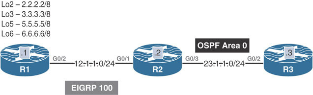
Configure the routers in the previous diagram based on the following chart. The loopback interfaces should be advertised with their correct masks. You may not see all the networks in every router.
Router | Router ID | Interface – Area |
|---|---|---|
R1 | 0.0.0.1 | Lo0 – Area 1 lo1 – Area 3 G0/2 – Area 1 |
R2 | 0.0.0.2 | Lo0 – Area 0 lo1 – Area 1 G0/1 – Area 1 G0/3 – Area 0 |
R3 | 0.0.0.3 | Lo0 – Area 0 lo1 – Area 2 G0/2 – Area 0 G0/4 – Area 2 |
R4 | 0.0.0.4 | Lo0 – Area 2 lo1 – Area 4 G0/3 – Area 2 G0/5 – Area 4 |
R5 | 0.0.0.5 | Lo0 – Area 4 G0/4 – Area 4 |
Task 2
Ensure that the networks advertised in Area 3 are reachable by the other routers. Do not use a GRE tunnel to accomplish this task.
Task 3
Ensure that the networks in Area 4 are reachable by the other routers. You should use a GRE tunnel to accomplish this task. The IP address of the tunnel should be based on the Lo1 interfaces of R3 and R4. Do not reconfigure the Loopback1 interfaces of these two routers.
Task 4
Erase the startup configuration and reload the routers before proceeding to the next lab.
Lab 10: Default Route Injection
This lab should be conducted on the Enterprise POD.
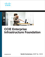
Task 1
Configure the routers in the previous topology. Do not configure any routing protocols.
Task 2
Configure EIGRP AS 100 on R1 and all of its directly connected interfaces and R2’s G0/1 interface.
Task 3
Configure OSPF on R3’s G0/2 interface and R2’s G0/3 interface in Area 0.
Task 4
Configure R2 to inject a default route into the OSPF routing domain if network 2.0.0.0/8 or 3.0.0.0/8 is up.
Task 5
Remove the configurations from the previous task and configure the appropriate router/s based on the following policy:
R2 should inject a default route into the OSPF routing domain only if networks 2.0.0.0/8 and 3.0.0.0/8 are both up.
Do not use route maps, access lists, or prefix lists to complete this task.
Task 6
Remove the configurations from the previous task and configure the appropriate router/s based on the following policy:
R2 should inject a default route into the OSPF routing domain only if network 2.0.0.0/8 is up and network 3.0.0.0/8 is down.
Task 7
Remove the configurations from the previous task and configure the appropriate router/s based on the following policy:
R2 should inject a default route into the OSPF routing domain only if networks 2.0.0.0/8 and 3.0.0.0/8 are both up.
R2 should not configure a static default route.
R2 should configure a prefix list to accomplish this task.
Task 8
Remove the configurations from the previous task and configure the appropriate router/s, based on the following policy:
R2 should inject a default route into the OSPF routing domain if network 2.0.0.0/8 is up
AND
Network 3.0.0.0/8 is down
AND
Networks 5.0.0.0/8 OR 6.0.0.0/8 are both up.
Task 9
Erase the startup configuration and reload the devices before proceeding to the next lab.
Lab 11: OSPF Authentication
This lab should be conducted on the Enterprise POD.
Lab Setup:
If you are using EVE-NG, and you have imported the EVE-NG topology from the EVE-NG-Topology folder, ignore the following tasks and use Lab 11-OSPF Authentication in the OSPF folder in EVE-NG.
To copy and paste the initial configurations, go to the Initial-config folder → OSPF folder→ Lab-11.
Task 1
Configure the directly connected interfaces of all routers in Area 0. The router IDs of the routers in this area should be configured as 0.0.0.x, where x is the router number.
Task 2
Configure plaintext authentication on all the links connecting the routers in this area. You must use a router configuration command as part of the solution in resolving this task. Use aaa as the password for this authentication.
Task 3
Remove the authentication configuration from the previous task and ensure that every router sees every route advertised in Area 0.
Task 4
Configure MD5 authentication on all the links in Area 0. You should use a router configuration command as part of the solution to this task. Use ccc as the password for this authentication.
Task 5
Remove the authentication configuration from the previous task and ensure that every router sees every route advertised in Area 0.
Task 6
Configure MD5 authentication on the link connecting R1 to R2. You should use a router configuration command as part of the solution to this task. The password should be ccie.
Task 7
Reconfigure the authentication password on R1 and R2 to be CCIE12, without interrupting the link’s operation. Do not remove any commands to accomplish this task.
Task 8
Configure MD5 authentication on the link that connects R4 to R5, using Cisco45 as the password. You should not use a router configuration mode to accomplish this task.
Task 9
Reconfigure OSPF areas based on the following chart:
Router | Interface | Area |
|---|---|---|
R1 | G0/2 Loopback0 | 0 0 |
R2 | G0/1 G0/3 Loopback0 | 0 1 1 |
R3 | G0/2 G0/4 Loopback0 | 1 2 2 |
R4 | G0/3 G0/5 Loopback0 | 2 3 3 |
R5 | G0/4 Loopback0 | 3 3 |

Task 10
Configure MD5 authentication on the link between R1 and R2 in Area 0. The password for this authentication should be set to Micronics. You should use router configuration mode to accomplish this task.
Task 11
Configure the strongest authentication between R4 and R5. Configure the password to be PSWD.
Task 12
Erase the startup configuration and reload the routers before proceeding to the next lab.
Lab 12: OSPF Best-Path Determination

This lab should be conducted on the Enterprise POD.
Lab Setup:
If you are using EVE-NG, and you have imported the EVE-NG topology from the EVE-NG-Topology folder, ignore the following tasks and use Lab 12-OSPF Bestpath Determination in the OSPF folder in EVE-NG.
To copy and paste the initial configurations, go to the Initial-config folder → OSPF folder→ Lab-12.
Task 1
Configure OSPF on the routers in the previous topology based on the following policy:
Configure OSPF Area 0 on the link connecting R1 to R2. R2 should run OSPF Area 0 on all of its directly connected interfaces. R1 should use OSPF PID 12, and R2 should use OSPF PID 1.
Configure OSPF Area 0 on the link connecting R1 to R3. R3 should run OSPF Area 0 on all of its directly connected interfaces. R1 should use OSPF PID 13, and R3 should use OSPF PID 1.
Configure OSPF Area 0 on the link connecting R1 to R4. R4 should run OSPF Area 0 on its G0/1 interface and Area 4 on its Loopback0 interface.
Configure OSPF Area 0 on the link connecting R1 to R5. R5 should redistribute its Loopback0 interface as external Type 2 in this routing domain.
Configure OSPF Area 0 on the link connecting R1 to R6. R6 should redistribute its Loopback0 interface as external Type 1 in this routing domain.
Configure OSPF Area 7 on the link connecting R1 to R7. Area 7 should be configured as an NSSA. R7 should redistribute its Loopback0 interface as external Type 2 in this routing domain.
Configure OSPF Area 8 on the link connecting R1 to R8. Area 8 should be configured as an NSSA. R8 should redistribute its Loopback0 interface as external Type 1 in this routing domain.
Task 2
Walk through OSPF best-path determination.
Task 3
Erase the startup configuration and reload the routers before proceeding to the next lab.
Lab 13: OSPF Challenge Lab

This lab should be conducted on the Enterprise POD.
Lab Setup:
If you are using EVE-NG, and you have imported the EVE-NG topology from the EVE-NG-Topology folder, ignore the following tickets and use Lab 13-OSPF Challenge Lab in the OSPF folder in EVE-NG.
To copy and paste the initial configurations, go to the Initial-config folder → OSPF folder→ Lab-13.
Rules:
The DMVPN should not be changed to dynamic.
You should only fix the problem that is specified in the ticket.
Ticket 1
R5 can’t ping R3’s Lo0 interface.
Ticket 2
R2 can’t reach R5’s Lo0 interface. There should be a DR. Do not use neighbor command when fixing this problem.
Ticket 3
R1 can’t ping R5’s Lo0 interface. You must use an OSPF command to fix this problem.
Ticket 4
R4 is configured to filter R3’s Lo0 interface from reaching R6. R6 should have reachability to all loopback interfaces in this topology except R3’s Lo0 interface. However, this is not the case. R6 should not get any error messages regarding tunnel interfaces. Use two other commands to fix other problems on R6. R6 should not have 6.14.0.3/32 in its routing table after you fix the other problems.
Ticket 5
R5 is configured to inject a default route if R3’s Lo0 interface is reachable. However, R5 is not injecting a default route. You can remove and reconfigure a command on the appropriate router once, but you must use the same method.
Ticket 6
R2 is configured to summarize R1’s loopback interfaces (Lo100–Lo103). However, R5 can see all the specific routes of the summary in its routing table. Do not remove any commands to accomplish this task.
Ticket 7
R3 is participating in another OSPF routing domain, using the process ID 378. R3 has two neighboring routers, R7 and R8. R7 and R8 are both summarizing their identical specific routes. R3 should use R7 and not R8 to reach the summary route. If router R7 is down, then R3 should go through R8 to reach the summary. Do not use the following on any router to accomplish this task:
Cost
Bandwidth
Static routes
PBR
Any kind of tunneling
Running extra routing process
Ticket 8
Erase the startup configuration and reload the devices before proceeding to the next lab.