Chapter 11
SD-Access
The Introduction to SD-Access and DNA Center to enterprise network deployments gives the organization access to Cisco’s latest features to automate common administrative tasks on security-focused programmable network infrastructures. This chapter will demonstrate the concept of a “Network Fabric” and the different node types that form it (Fabric Edge Nodes, Control Plane Nodes, Border Nodes). It demonstrates the roles of LISP in the Control Plane and VXLAN in the Data Plane for SD-Access Solutions and how DNA Center uses them to automate security and network access.
The following topology will be used for all the SDA labs:

Lab 1: Configuring the SDA Policy Engine
Task 1: ISE Integration with DNA Center
Log in to ISE using a browser by navigating to https://ise.micronicslab.com/. The IP address of ISE is 100.64.0.120. Use the following credentials:
Username: admin
Password: ISEisC00L

Navigate to Administration > System > Deployment and then click OK when you see the informational message shown below:


Enable the services SXP Service, Device Admin Service, Passive Identity Service, and pxGrid, as shown below, and click Save.

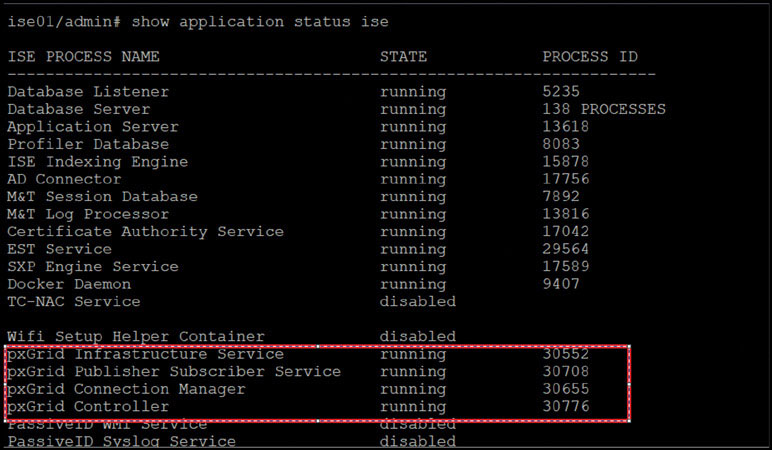
Navigate to Administration > pxGrid Services and check the banner in the lower half of the screen. You should see “connected via XMPP” followed by the FQDN of ISE, as shown below. Make note of the FQDN, which you will need later. Keep in mind that this banner might be red in color initially because pxGrid services take some time to initialize. You can check the status of the services by logging in to ISE via the CLI and typing the command show application status ise.

You should see output like the following:
Navigate to Administration > System > Settings > ERS Settings. Then, under ERS Setting for Primary Administration Node, select Enable ERS for Read/Write and click OK in any dialog box that appears.
Under ERS Setting for All Other Nodes, select Enable ERS for Read, and under CRSF Check, select Disable CSRF for ERS Request, and then click Save.
Click OK in any additional dialog boxes that appear.


Task 2: Finalize the Integration on DNA Center
Log in to the DNA Center web interface (https://100.64.0.101), at the top-right corner select the gear icon, and select System Settings. Use the following credentials:
Username: admin
Password: ISEisC00L

Navigate to Settings > Authentication and Policy Servers and then click Add:

In the Add AAA/ISE Server display shown below, enter the ISE node (Primary PAN) IP address along with the details shown below:
Server IP Address | 100.64.0.120 |
Shared Secret | ISEisC00L |
ISE Selector | Toggle it to the on position |
ISE Username | admin |
ISE Password | ISEisC00L |
ISE FQDN | |
Subscriber Name | DNAC1.3.1.7 |
SSH Key | <Leave Blank> |
View Advanced Settings | Check TACACS and RADIUS |
Note
For this lab you will be using TACACS for network authentication and RADIUS for client authentication.

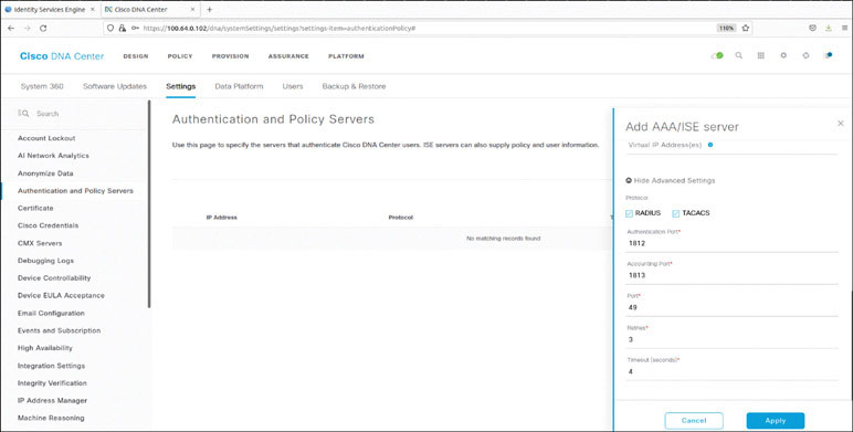
Click Apply.
Log in to ISE and navigate to Administration > pxGrid Services. The client named dnac1.3.1.7_dnac_ndp is now showing Pending in the Status column.

Choose Total Pending Approval (1), click Approve All, and click Approve All again to confirm.

A success message appears.
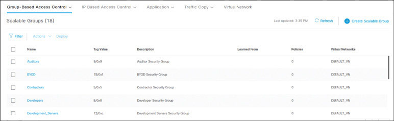
If ISE is integrated with DNA Center after scalable groups are already created in ISE, in addition to the default groups, any existing ISE groups will also be visible. You can see these entries by logging in to DNA Center and navigating to Policy > Group-Based Access Control > Scalable Groups, as shown below:
For this exercise, you will use DNA Center to implement group-based access control. Click Start Migration, observe the warning message, shown below, and click Yes.

When the process is complete you will see the following success message.


You should now see some additional Scalable Groups added (ACCT, HR, Campus Quarantine).
Lab 2: SDA Design
Task 1: Design the Network Hierarchy
Log in to ISE by using a browser to navigate to the IP address 100.64.0.120. Use the following credentials:
Username: admin
Password: ISEisC00L

Log in to DNA Center by using a browser to navigate to https://100.64.0.101. Use the following credentials:
Username: admin
Password: ISEisC00L

In DNA Center, go to DESIGN > Network Hierarchy, click Add Site, and select Add Area, as shown below:

Enter US for the area name and click Add:

Click the cog wheel next to US in the navigation pane and choose Add Area. In the Add Area window, as shown on the next page, enter San Jose for the area name and click Add.
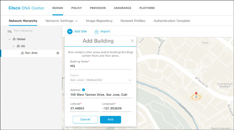
To add a building, select the cog wheel next to San Jose in the navigation pane and click Add Building. Enter the building name HQ and begin to enter the street address shown on the next page. Click on the correct option from among the street address recommendations that appear to autopopulate the Latitude and Longitude fields. Click Add when you’re done with this.

With the building now defined, select HQ in the navigation pane, click the gear icon, and select Add Floor, as shown on the next page:

In the Add Floor window, enter HQ-1 as the floor name and click Upload File.

Note
You should have floor plans and other files in the Downloads folder. Open it and select the Floor Plan folder. Look for HQ-1.png in this the folder and click Open to upload it.
DNA Center presents the floor plan file, as shown below.
Click Add to create the floor.


Return to HQ in the navigation pane, click the gear icon, and select Add Floor again to create another floor.

Name the new floor HQ-MDF and click Add. (You do not need to upload a floor plan in this case.)
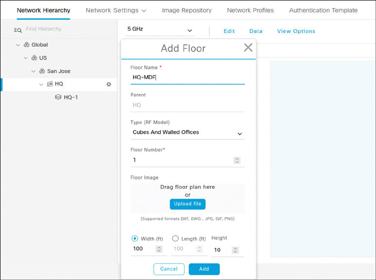
Click OK to acknowledge the warning message and proceed without a floor plan for this floor.

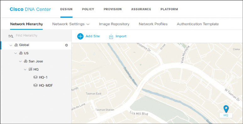
At this point, the building and floors necessary for this lab have been created. Observe the hierarchy you have built in the navigation pane shown below:
Task 2: Configure Common Network Settings
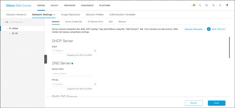
In DNA Center, navigate to DESIGN > Network Settings > Network, as shown below.
Ensure that Global is selected in the navigation pane and click Add Servers.
Check the AAA and for NTP boxes and click OK:

Notice that the AAA Server section is present. If you scroll to the bottom of the page, you also see an NTP section. Check the Network and Client/Endpoint boxes under AAA Server to reveal more options, as shown on the next page.

As shown below, in the Network section, select the ISE server 100.64.0.120 under both Network and IP Address (Primary).
In the CLIENT/ENDPOINT section the ISE radio button under Servers and the RADIUS radio button under Protocol.

Set the DHCP server to 100.64.0.2, as shown below, and carefully enter the domain name micronics.com and the internal DNS server 100.64.0.2.

Under NTP Server, enter 100.64.0.2 as the time source. Keep in mind that this is the CSR in the cloud that is providing time for the devices in the setup.

With all the Network Settings input at the Global Level, as shown below, click Save.

Confirmation messages like the ones below appear briefly at the bottom right of the screen:

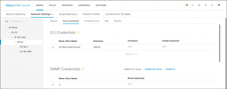
Task 3: Configure Device Credentials
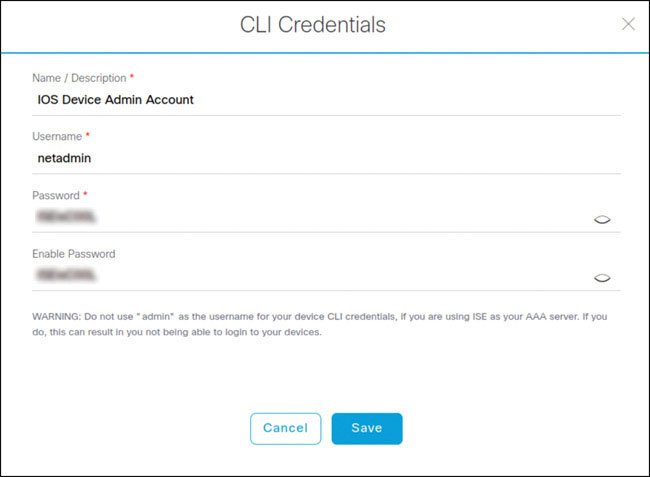
Navigate to DESIGN > Network Settings > Device Credentials, click Add Credentials. In the CLI Credentials box, shown below, enter the following credentials:
CLI credentials name: IOS Device Admin Account
Username: netadmin
Password/enable password: ISEisC00L
Click Save.
Click SNMP v2c and Read and enter the following credentials:
Name: ro
Read community: ro
Click Save.
Click SNMP v2c and Write, as shown on the next page, and enter the following credentials:
Name: rw
Write community: rw
Click Save.

To set the CLI credentials and the SNMP read and write community strings that just you added as global, click on the radio button to the left of CLI Credentials and click the radio button to the left of SNMP Credentials. (This first click will be for the read-only credentials.)
Next, click the SNMPV2C Write link in the center in the SNMP Credentials section. (When you click this link, notice that ro switches to rw in the Name/Description field.)

Click the radio button to the left of rw to select the read/write credentials.
Click Save.

Watch for the small success message that appears briefly in the bottom right of the screen:

Task 4: Create and Reserve IP Address Pools
To create an IP address pool, go to DESIGN > Network Settings > IP Address Pools. Make sure Global is selected in the navigation pane and click Add.
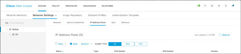
The Add IP Pool dialog box shown below appears:
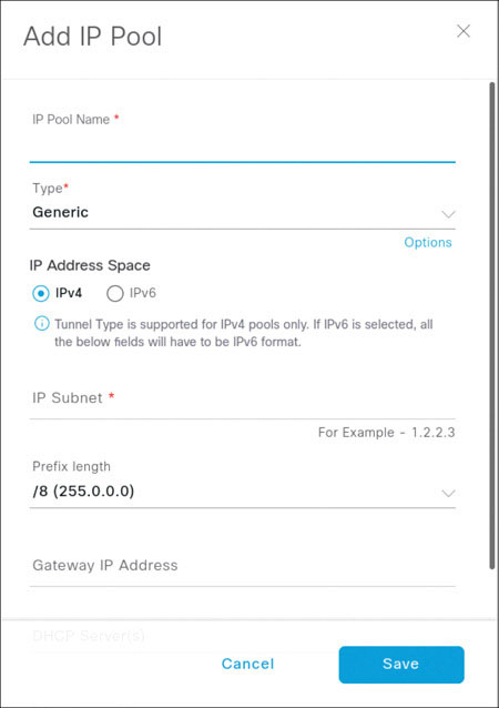
Populate the fields of the Add IP Pool dialog box as shown on the next page, using the following details:
IP Pool Name: Global-Pool-1
Type: Generic
IP Subnet: 100.96.0.0
CIDR Prefix: /11 (255.224.0.0)
Gateway: 100.96.0.1
Click Save.
It is not necessary to populate DHCP and DNS servers at the global pool level.

To reserve IP pools, in DNA Center, go to DESIGN > Network Settings > IP Address Pools and, as shown on the next page, navigate to San Jose in the navigation pane. The message shown on the next page appears, describing how the hierarchy works. Check the Don’t show again box and click OK to prevent this message from appearing again in the future.
If you misconfigure a pool reservation, ensure that you release the IP pool and re-create it.

With San Jose still selected, click Reserve the IP Address Pools.

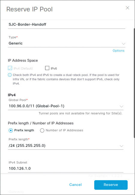
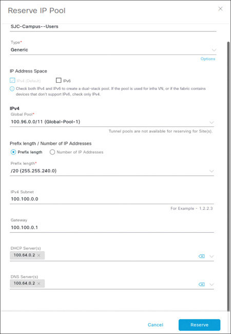
In the Reserve IP Pool dialog box that appears, as shown on the next page, enter the following information to create a new reservation within the global IP pool you just created:
IP pool name: SJC-Border-Handoff
Type: Generic
Global Pool: 100.96.0.0/11 (Global-Pool-1)
Prefix Length: /24
IPv4 Subnet: 100.126.1.0
Gateway: 100.126.1.1
Click Reserve.
Enter the following information to create a new reservation within the global IP pool you just created:
IP pool name: SJC-Campus-Users
Type: Generic
Global Pool: 100.96.0.0/11 (Global-Pool-1)
Prefix Length: /20
IPv4 Subnet: 100.100.0.0
Gateway IP Address: 100.100.0.1
DHCP Server: 100.64.0.2
DNS Server: 100.64.0.2
Click Reserve.
Enter the following information to create a new reservation within the global IP pool you just created:
IP pool name: SJC-Guest-Users
Type: Generic
Global Pool: 100.96.0.0/11 (Global-Pool-1)
Prefix Length: /20
IPv4 Subnet: 100.99.0.0
Gateway: 100.99.0.1
DHCP Server: 100.64.0.2
DNS Server: 100.64.0.2
Click Reserve.

Enter the following information to create a new reservation within the global IP pool you just created:
IP pool name: SJC-Lan-Automation
Type: Lan
Global Pool: 100.96.0.0/11 (Global-Pool-1)
Prefix Length: /20
IPv4 Subnet: 100.124.128.0
Gateway: 100.124.128.1
Click Reserve.

At this point, you have created all the IP pools you need to build out the SDA fabric in this lab. You can see them listed in the screen shown below:

Lab 3: Building the SDA Campus Fabric
Task 1: Discover Devices
Log in to DNA Center using a browser by navigating to the IP address https://100.64.0.101/ and entering the following credentials:
Username: admin
Password: ISEisC00L


In DNA Center, click the gear icon and select Discovery, as shown below:
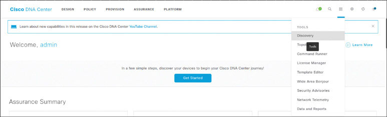
On the Discovery Dashboard, click Add Discovery. Note that you can get a snapshot of the devices along with details associated with discovery jobs. The aim of this discovery job is to discover the devices that you are going to add to DNA Center manually. Once the devices are added, you will begin configuring them.

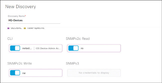
Enter HQ_Devices as the name of the discovery job and select the IP Address/Range radio button. Enter the From and To IP address range 100.124.0.1 to 100.124.0.2, as shown on the next page. This will encompass the cp-border-1 and cp-border-2 devices. Under Preferred Management, select UseLoopBack.

Scroll down until you see the credentials that were populated in Lab 2 appear as selectable parameters that can be used for this discovery job. (During Lab 2, you made these credentials globally available for all discovery jobs by selecting the radio button.) The credentials should already be selected for use, and the slider can be toggled on or off.
Scroll down further, until you see the Advanced option. Expand this option and select Telnet as well as SSH, in case there are devices that aren’t configured for SSH.
When you see the warning about enabling Telnet, click on OK.
You can change the order of the protocols in this window, moving Telnet above SSH, if required.

Click Discover and, in the window shown below, choose Now and click Start.

The Discovery starts, and DNA Center reaches out to the network, using a ping sweep on the IP address range you enumerated.
When the discovery job has completed and you see the side panel that lists the discovered devices, as shown below, make note of the green check marks.
Green is good. If you see any red icons, however, a failure has occurred, and the device will not be onboarded into DNA Center as a managed device. For example, if the SNMP credentials were incorrect, DNA Center would let you know that SNMP validation failed.

Navigate to the DNA Center home page and go to the PROVISION Page. Notice that the devices show up on this page as Unassigned Devices in the navigation pane. You will be fixing this soon. For now, set the Device Role for the CP border devices to Border Router if the status of these devices is listed and UNKNOWN otherwise. Give the system time to identify the devices. The system will discover these switches as ACCESS devices.

Task 2: Provisioning the Devices
From the jumphost, open a session to cp-border-1. This is a reverse Telnet console session to cp-border-1. Use the following credentials, if requested
Username: netadmin
Password: ISEisC00L

Run a quick check on the configuration of the cp-border-1 device before initiating the provisioning process from DNA Center. To do so, issue the following commands:
show run | sec lisp
show run | sec isis
show run | sec vrf
show run | sec aaa
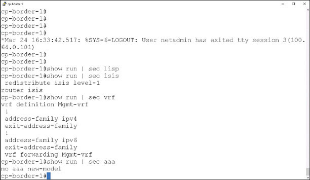
Notice that there is no LISP-related configuration, no additional VRF instances have been created, and there is a rudimentary ISIS configuration. In addition, there is no AAA configuration on this device at this point.
Log in to the Edge01 device via Putty, using the following credentials:
Username: netadmin
Password: ISEisC00L

When you are presented with a screen asking you to start the initial configuration, like the one shown below, do not press any keys. It is expected that this device will be in a factory default state because you will be onboarding your edge devices via LAN automation:

To quickly review the configuration from Lab 2, navigate to DESIGN > Network Hierarchy in DNA Center, as shown on the next page:
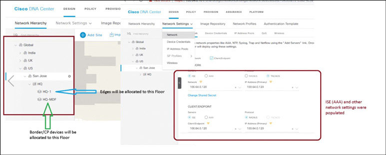
Recall that in Lab 2, you set up a Network Hierarchy and configured various common network settings (such as AAA). As part of the provisioning process, you need to assign a site to each network device. The network device will inherit settings from that site. Edges will be assigned to the floor HQ-1, and border routers will be assigned to the floor HQ-MDF. They will inherit the common network settings accordingly (the same settings in this case).
Navigate to the PROVISION page on DNA Center. Notice, as shown below, that there aren’t any devices at the lower levels (for example, San Jose), but there are two unassigned devices.
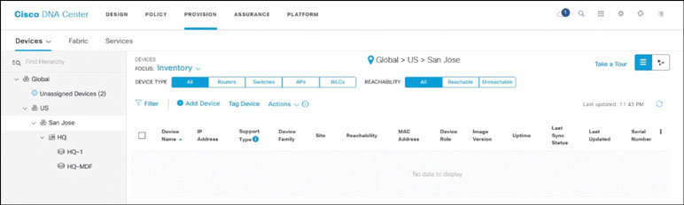
Click on Unassigned Devices in the navigation pane. You now see all the devices that were discovered in this section, as shown below.

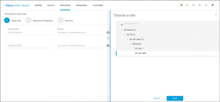
Select all the devices, as shown below, and select Action, click Provision, and click Provision Device.

Allocate the devices to the respective sites by clicking Choose a Site. Assign devices as follows:
Assign cp-border-1 to Global/US/San Jose/HQ/HQ-MDF
Assign cp-border-2 to Global/US/San Jose/HQ/HQ-MDF
Click Next.
Click Next on the Advanced Configuration page. This page is used to deploy templates to devices via the Template Editor tool (which allows you to push custom configuration to the devices during provisioning). Click Deploy on the Summary page.

Select Now and click Apply to apply the configuration immediately.

Give the devices some time to be provisioned. When the provisioning process is complete, you should see a temporary notification in the bottom-right corner, indicating that provisioning was successful.

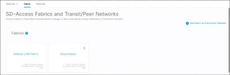
Now that the devices have been provisioned, you can add the fabric and add the devices to the fabric. To add a new fabric, as shown below, navigate to PROVISION > Fabric and, in the top-right corner, click Add Fabric or Transit/Peer Network and then click Fabric:
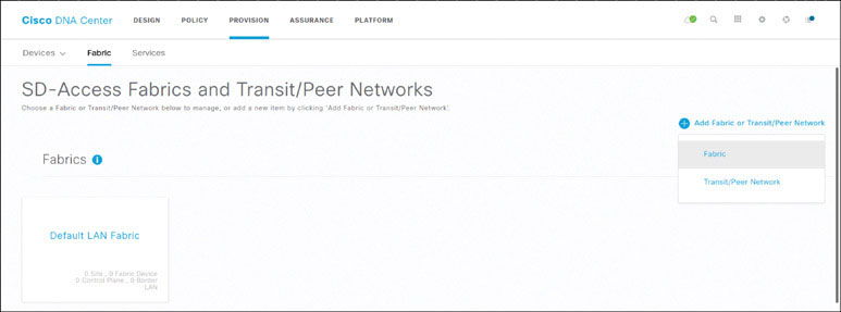
In the side panel that appears, select the San Jose site as your fabric site.
Note
Keep in mind that the site should be selected appropriately so that network settings (such as IP pools) from that site can be used. If the fabric site is at a level higher than the site where configuration parameters like IP pools have been allocated, they will not be usable.
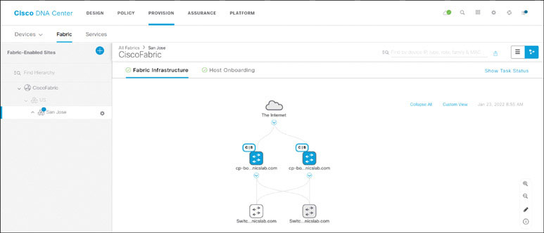
Name the fabric CiscoFabric and select the San Jose site. Click Next. Make sure both virtual networks created so far (built-in virtual networks) are selected, as shown on the next page, and click Add.

Click on the CiscoFabric fabric that you just created, as shown below, to start configuring devices in it.
Click on San Jose in the navigation pane and then click on cp-border-1.
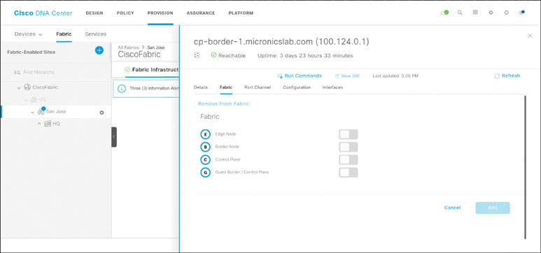
In the sliding panel that appears, set the slider for Border Node to the On position. This should bring up a panel where you need to enter the AS number 65534 and check the Default to all Virtual Networks checkbox. Click Add.

Set the slider for Control Plane to the On position. Click Add.

Repeat the previous operations for cp-border-2, as shown below:

Ensure that the devices that you have configured have a blue outline around them now. This is an indication that these devices will be configured when you click Save. Also make sure there is a pointer that specifies the role(s) configured on that device.
Click Save, select Now, and click Apply.

You should see a notification indicating that the devices were successfully configured in the fabric domain.
Issue show run | sec lisp on any of your devices, and you should see the LISP configuration shown on the next page. (Keep in mind that the configuration will be different for devices with different roles.)

Lab 4: LAN Automation
In this lab we will explore how to conduct a LAN Automation exercise.
Log in to DNA Center by using a browser to navigate to the IP address https://100.64.0.101/ and entering the following credentials:
Username: netadmin
Password: ISEisC00L
From the jumphost, open a console session to cp-border-1 so you can use LAN automation for the devices edge-01 and edge-02.
In DNA Center, navigate to DESIGN > Network Settings > Device Credentials. Verify that the CLI and SNMP ro and rw credentials have been selected, as partially shown below:
Verify that an IP pool has been reserved for LAN automation, as shown below:

You need to ensure IP connectivity from DNA Center to the LAN automation pool addresses. This can be achieved in multiple ways, such as by using a routing protocol to advertise the subnet from the border(s) out to the fusion, using static routing to DNA Center, or using border automation.
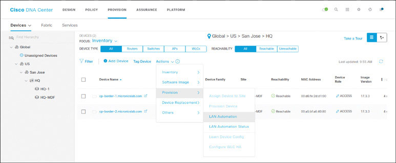
Go to PROVISION > Actions > Provision > LAN Automation, as shown on the next page, to start the LAN automation procedure.
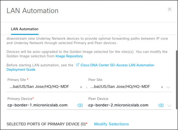
Enter the following details in the LAN Automation slide-out panel:
CONFIGURATION PARAMETER | VALUE |
|---|---|
Primary Site | Global/US/San Jose/HQ/HQ-MDF |
Primary Device (primary seed device) | |
Peer Site | Global/US/San Jose/HQ/HQ-MDF |
Peer Device (peer seed device) | |
Choose primary device ports | Gi1/0/13 and Gi1/0/14 |
Discovered device site | Global/US/San Jose/HQ/HQ-1 |
IP Pool | SJC-Lan-Automation |
IS-IS Domain Password | Cisco |
Click on Start to start the LAN automation procedure.


Wait for approximately 120 seconds and view the LAN automation status by navigating to PROVISION > Actions > Provision > LAN Auto Status.
You should see some action in the LAN Automation Status screen. In the figure below, a device has been discovered via LAN automation, and the procedure for it is in progress.
Note
You should see Gi1/0/13 and Gi1/0/14 as the primary device interfaces.

Check the console session for edge-01 and edge-02. You should see some activity with respect to PnP.
Check the LAN automation status after some time, and you should see two devices listed as Completed (edge-01 and edge-02), as shown on the next page:

Go to the PROVISION page, and you should now see your LAN automated devices popping up. It might take a while before all the devices show up because DNA Center collects information from the devices during the automation process and tries to bring them into a managed state before populating all the information. In the interim, some devices might show up as N/A.

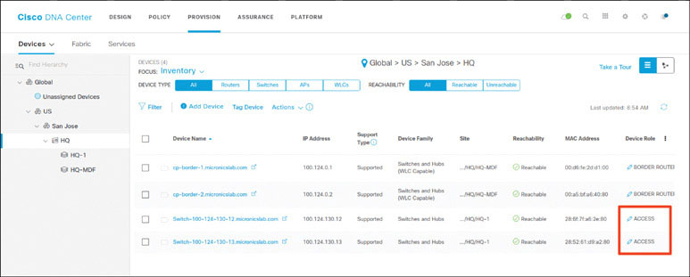
After a while, notice that both devices are added to the inventory and are being managed by DNA Center.

Since you are confident at this point that LAN automation has completed successfully, close out the process by choosing STOP on the DNA Center LAN Automation Status screen. You see that ISIS neighborships are now established on the physical interfaces, and IP addresses are being assigned to the interfaces from the LAN automation IP pool created on DNA Center. IP addresses from VLAN 1 and the DHCP pool are removed:


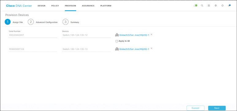
To provision the LAN automated devices and add them to the fabric as edge nodes, go to the PROVISION page, select both of the LAN automated devices, and choose Actions > Provision > Provision Device, as shown below:

Assign both devices to Global/US/San Jose/HQ/HQ-1 and click Next.
Click Next in the Advanced Configuration screen and then click Deploy on the Summary page. Select Now and click Apply.

To set the role of all LAN automated devices to Access, go on the PROVISION page.
Navigate to the Fabric tab, click the CiscoFabric fabric, click San Jose, and notice the three LAN automated devices there. Click on them one by one and set the role to Edge Node. Click Add.

When the devices have been added to the fabric, ensure that the fabric view is similar to what is displayed below (notice the blue shade on the devices, which means they have been added to the fabric successfully):

Validate the configuration by using the command show lisp service ipv4, as shown below:
