Chapter 1
Switching
Lab 1: Configuring Trunks
What is covered in this lab:
This lab focuses mainly on configuring trunk links and VLANs and controlling which VLANs are allowed on a particular trunk link. This lab covers the following topics: dynamic trunks, basic VTP operation, how to modify the allowed VLAN lists on trunk links, and VTP pruning.
This lab should be conducted on the Enterprise POD.
Task 1
Shut down all ports on all six switches and configure the VTP domain name to be TST.
Task 2
Configure the following hostnames:
Second switch: SW2
Third switch: SW3
Fourth switch: SW4
Fifth switch: SW5
Task 3
Configure a dot1q trunk between SW3 and SW5 using their E5/0 interfaces, based on the following policy:
SW3, E5/0
This port should be configured into a permanent trunk mode, and it should negotiate to convert the neighboring interface into a trunk.
SW5, E5/0
This port should be configured to actively attempt to convert the link to a trunk. You should not configure switchport trunk encapsulation dot1q on this port.
Task 4
Configure a trunk between SW3 and SW5, using their E5/1 interfaces. You should use an industry-standard protocol for the trunk encapsulation, based on the following policy:
SW3, E5/1
This port should be configured into permanent trunk mode, and it should negotiate to convert the neighboring interface into a trunk.
SW5, E5/1
This port should be configured to negotiate a trunk only if it receives negotiation packets from a neighboring port; this port should never start the negotiation process. You should not configure switchport trunk encapsulation dot1q on this port.
Task 5
Configure a trunk link between SW4 and SW5, using their E4/0 interfaces. These ports should be configured to negotiate the neighboring interface into a dot1q trunk, but they should not be in permanent trunk mode.
Task 6
Configure a dot1q trunk between SW4 and SW5, using their E4/1 interfaces, based on the following policy:
SW4, E4/1
This port should be configured to actively attempt to convert the link to a trunk. This port should not be in permanent trunk mode.
SW5, E4/1
This port should be configured to negotiate a trunk only if it receives negotiation packets from a neighboring port; this port should never start the negotiation process or be configured with the switchport trunk encapsulation dot1q command.
Task 7
Configure a dot1q trunk between SW3 and SW4, using their E6/0 interfaces; these switches should be configured into permanent trunk mode and negotiate the neighboring interface into a trunk.
Task 8
Configure a dot1q trunk between SW3 and SW4, using their E6/1 interfaces. These ports should not use DTP to negotiate a trunk.
Task 9
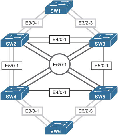
Configure trunking on the E4/0-1 interfaces of SW2 and SW3, the E5/0-1 interfaces on SW2 and SW4, and the E6/0-1 interfaces of SW2 and SW5. These ports should be in permanent trunk mode.
Task 10
Configure the following VLANs on SW2 and ensure that they are propagated to the other switches:
VLANs 2–10, 100, 200, 300, 400, 230, 350, 450, 240, 250, and 340
Task 11
Configure the trunks based on the following policy:
Policy Item | Trunk Interface | Between Switches | Allowed VLAN/s |
|---|---|---|---|
1 | E4/1 | SW2 ←→ SW3 | Only 230 |
2 | E5/0 | SW3 ←→ SW5 | Only 350 |
3 | E4/0 | SW4 ←→ SW5 | Only 450 |
4 | E5/0 | SW2 ←→ SW4 | Only 240 |
5 | E6/0 | SW2 ←→ SW5 | Only 250 |
6 | E6/0 | SW3 ←→ SW4 | Only 340 |
Task 12
Add VLANs to the allowed list of the trunks, based on the following chart:
Policy Item | Trunk Interface | Between Switches | Add to the Allowed VLAN/s |
|---|---|---|---|
1 | E4/1 | SW2 ←→ SW3 | 100 |
2 | E5/0 | SW3 ←→ SW5 | 200 |
3 | E4/0 | SW4 ←→ SW5 | 300 |
4 | E6/0 | SW2 ←→ SW5 | 400 |
Task 13
Remove VLANs from the allowed list of trunks, based on the following chart:
Policy Item | Trunk Interface | Between Switches | Allowed VLAN/s |
|---|---|---|---|
1 | E5/1 | SW2 ←→ SW4 | Remove 1, 4 – 10 only |
2 | E5/1 | SW3 ←→ SW5 | Remove 2, 4 – 10 only |
Task 14
Configure SW2, SW3, and SW5, based on the following chart:
Policy Item | Trunk Interface | Between Switches | Allowed VLAN/s |
|---|---|---|---|
1 | E4/0 | SW2 ←→ SW3 | None |
2 | E6/1 | SW2 ←→ SW5 | None |
Task 15
Configure SW2, SW4, and SW5, based on the following chart:
Policy Item | Trunk Interface | Between Switches | Allowed VLAN/s |
|---|---|---|---|
1 | E4/1 | SW4 ←→ SW5 | All except 450 |
2 | E5/1 | SW2 ←→ SW4 | All except 240 |
Task 16
Configure SW3 and SW4, based on the following chart. You may override some of the previous tasks to accomplish this task.
Policy Item | Trunk Interface | Between Switches | Allowed VLAN/s |
|---|---|---|---|
1 | E6/0 | SW3 ←→ SW4 | All |
2 | E6/1 | SW3 ←→ SW4 | All |
Task 17
Erase the config.text and vlan.dat files on SW1-5 and reload them before proceeding to the next task.
Task 18
Configure SW2 and SW3 based on the following policies:
Configure the hostnames of Switch 2 and Switch 3 to be SW2 and SW3, respectively.
Shut down all the ports on SW2 and SW3.
Configure a dot1q trunk between SW2 and SW3 using port E4/0.
Ensure that both switches belong to the VTP domain TST.
Task 19
Configure VLAN 100 on SW2 and assign its E0/1 interface to this VLAN.
VTP Pruning
In Task 10, it was explained that VTP is a protocol that can be used to synchronize the VLAN databases between switches that participate in the same VTP domain. VTP uses three message types to achieve this synchronization: summary advertisement, advertisement request, and subset advertisements. This synchronization process makes it such that an administrator only needs to configure VLANs on a single VTP server switch and have those configurations propagated for synchronization to all remaining switches in the VTP domain.
VTP can be used for more than simple VLAN database synchronization. It can be used to reduce unnecessary broadcast flooded traffic originating in a specific VLAN from entering sections of the network that do not require that VLAN traffic. For example, the sample topology from Task 10 is examined:

In this topology, the interfaces connecting Switch-1 to Switch-2 and Switch-3 are configured as trunk links. All three switches belong to the same VTP domain, TST.
Previously, VLAN 100 was created on Switch-1. Switch-1 propagated information about this VLAN to Switch-2 and Switch-3 using VTP. Looking at the diagram, notice only Switch-1 and Switch-3 have interfaces connected to hosts in VLAN 100. Switch-2 does not have any interfaces connected to VLAN 100. Since Switch-2 has no interfaces in VLAN 100, there is no need for it to receive broadcast traffic originating from hosts in VLAN 100 connected to other switches in the network. Recall, ARP requests are broadcasted to all devices in the same VLAN. They are generated by end hosts to resolve the MAC address of a target device.
When PC-1 needs to reach PC-3 in the topology, it starts by sending a broadcast ARP frame to learn PC-3’s MAC address. The following packet capture shows that the ARP frame was broadcasted to both Switch-2 and Switch-3:
On Switch-3:
Frame 4990: 64 bytes on wire (512 bits), 64 bytes captured (512 bits) on interface 0
Ethernet II, Src: aa:bb:cc:00:04:20 (aa:bb:cc:00:04:20), Dst: Broadcast
  (ff:ff:ff:ff:ff:ff)
802.1Q Virtual LAN, PRI: 0, DEI: 0, ID: 100
Address Resolution Protocol (request)
    Hardware type: Ethernet (1)
    Protocol type: IPv4 (0x0800)
    Hardware size: 6
    Protocol size: 4
    Opcode: request (1)
    Sender MAC address: aa:bb:cc:00:04:20 (aa:bb:cc:00:04:20)
    Sender IP address: 100.1.1.1
    Target MAC address: 00:00:00_00:00:00 (00:00:00:00:00:00)
    Target IP address: 100.1.1.2
On Switch-2
Frame 4134: 64 bytes on wire (512 bits), 64 bytes captured (512 bits) on interface 0
Ethernet II, Src: aa:bb:cc:00:04:20 (aa:bb:cc:00:04:20), Dst: aa:bb:cc:00:05:10
  (aa:bb:cc:00:05:10)
802.1Q Virtual LAN, PRI: 0, DEI: 0, ID: 100
Address Resolution Protocol (request)
    Hardware type: Ethernet (1)
    Protocol type: IPv4 (0x0800)
    Hardware size: 6
    Protocol size: 4
    Opcode: request (1)
    Sender MAC address: aa:bb:cc:00:04:20 (aa:bb:cc:00:04:20)
    Sender IP address: 100.1.1.1
    Target MAC address: aa:bb:cc:00:05:10 (aa:bb:cc:00:05:10)
    Target IP address: 100.1.1.2
Switch-2 has received the broadcast traffic even though it will ultimately drop it because it does not have any hosts in that VLAN. The VLAN 100 broadcast in this case was unnecessarily broadcasted to Switch-2. This unnecessary broadcast occurred because Switch-1 included VLAN 100 in its allowed VLAN list for the trunk link connected to Switch-2, as shown here:
Switch-1# show interfaces trunk

Port        Mode             Encapsulation  Status        Native vlan
Et0/0       on               802.1q         trunking      1
Et0/1       on               802.1q         trunking      1

Port        Vlans allowed on trunk
Et0/0       1-4094
Et0/1       1-4094

Port        Vlans allowed and active in management domain
Et0/0       1,100,200
Et0/1       1,100,200

Port        Vlans in spanning tree forwarding state and not pruned
Et0/0       1,100
Et0/1       1,100 ! VLAN 100 is allowed on the trunk link to Switch-2
This inclusion extends VLAN 100’s broadcast domain to Switch-2. One way to stop the unnecessary broadcast of VLAN 100 traffic to Switch-2 is to manually remove VLAN 100 from the Switch-1/Switch-2 trunk link by using the switchport trunk allowed-vlan remove 100 command in interface configuration mode. This process, called manual pruning, is demonstrated extensively in previous tasks.
The problem with manual pruning is that if a host were connected to Switch-2 in VLAN 100, that VLAN would need to be manually added to the allowed VLAN list on the Switch-1/Switch-2 trunk link again. Multiply this process by hundreds of VLANs and potentially hundreds of clients moving around in the network, and it is clear that this manual pruning process can cause high administrative overhead.
This is where VTP pruning comes into play. VTP pruning is a feature of VTP that allows dynamic pruning of VLANs from trunk links where the VLAN traffic is not needed. The process utilizes a fourth VTP message type, called the VTP membership advertisement, or VMA. These are basically VTP Join/Prune messages.
The basic process for VTP pruning is that a switch sends a VMA for all VLANs for which it is interested in receiving traffic. The switch makes this determination based on whether or not it contains any interfaces that are currently associated with a VLAN that exists in the local switch’s VLAN database.
Once again, referring back to the sample topology shown earlier, when VTP pruning is enabled on all the switches, they exchange VMAs with each other. Because Switch-3 is interested in receiving traffic for VLAN 100, its VMA includes VLAN 1 and VLAN 100, as shown in the following capture.
Note
VLAN 1 is pruning ineligible, which means this VLAN will always be included in the advertised active VLAN field and cannot be removed.
From Switch-3:
VLAN Trunking Protocol
    Version: 0x01
    Code: Join/Prune Message (0x04)
    Reserved: 00
    Management Domain Length: 3
    Management Domain: TST
    First VLAN ID: 0
    Last VLAN ID: 1007
    Advertised active (i.e. not pruned) VLANs
        VLAN: 1
        VLAN: 100
The Advertised active (i.e. not pruned) VLANs field indicates the VLANs for which Switch-3 is interested in receiving traffic. Any VLAN that is not assigned to an interface on Switch-3 is omitted from this list. For example, the VMA sent from Switch-2 to Switch-1 includes only VLAN 1. This is because Switch-2 does not have any interfaces assigned to VLAN 100, and thus it has no need for VLAN 100 traffic. Any traffic sent by Switch-1 to Switch-2 in VLAN 100 would inevitably be a futile effort since Switch-2 would end up dropping the traffic anyway.
From Switch-2
VLAN Trunking Protocol
    Version: 0x01
    Code: Join/Prune Message (0x04)
    Reserved: 00
    Management Domain Length: 3
    Management Domain: TST
    First VLAN ID: 0
    Last VLAN ID: 1007
    Advertised active (i.e. not pruned) VLANs
        VLAN: 1
The following shows the state of the show interface trunk output on Switch-1. As a result of the VMA message exchanges, Switch-1 will now send traffic for VLAN 100 out its trunk link E0/0 to Switch-3 only.
Switch-1# show interfaces trunk

Port        Mode             Encapsulation  Status        Native vlan
Et0/0       on               802.1q         trunking      1
Et0/1       on               802.1q         trunking      1

Port        Vlans allowed on trunk
Et0/0       1-4094
Et0/1       1-4094

Port        Vlans allowed and active in management domain
Et0/0       1,100,200
Et0/1       1,100,200

Port        Vlans in spanning tree forwarding state and not pruned
Et0/0       1,100 ! VLAN 1 and 100 allowed to Switch-2
Et0/1       1 ! Only VLAN 1 allowed to Switch-2
VTP pruning is disabled by default and can be enabled by using the vtp pruning command in global configuration mode. VTP keeps a list of VLANs that are allowed to be dynamically pruned; it is called the pruning-eligible list or the pruning VLANs enabled list, depending on the show command being used. This list can be seen using the show interface switchport command, as shown here:
Switch-1# show int e0/0 switchport | in Pruning
Pruning VLANs Enabled: 2-1001
The pruning-eligible list can be modified much like the allowed VLAN list of a trunk link with the switchport trunk pruning vlan command and the following additional parameters:
Switch-1(config-if)# switchport trunk pruning vlan ?
  WORD    VLAN IDs of the allowed VLANs when this port is in trunking mode
  add     add VLANs to the current list
  except  all VLANs except the following
  none    no VLANs
  remove  remove VLANs from the current list
The result of this command can be seen with the sample topology shown earlier. Before any configuration changes are made, the show interface e0/1 pruning command output on Switch-1 reveals that it is pruning VLAN 100 on the E0/1 trunk link connected to Switch-2. This is a result of the missing VLAN 100 in the VMA sent by Switch-2, as shown here:
Switch-1# show interface e0/1 pruning

Port                Vlans pruned for lack of request by neighbor
Et0/1               100

Port                Vlan traffic requested of neighbor
Et0/1               1,100
Next, VLAN 200 is configured on Switch-2. The pruning-eligible list on Switch-2 is then modified to include only VLAN 200 with the switchport trunk pruning vlan 200 command:
Switch-2(config-if)# vlan 200
Switch-2(config-vlan)# exit
Switch-2(config)# interface e0/1
Switch-2(config-if)# switchport trunk pruning vlan 200
Notice how the pruning-eligible list on Switch-2 shows only VLAN 200:
Switch-2# show interface e0/1 switchport | in Pruning
Pruning VLANs Enabled: 200
The result of this configuration is that all other VLANs are now considered to be pruning ineligible. As a result, the VMA sent by Switch-2 to Switch-1 will include VLAN 100, thus preventing Switch-1 from pruning this VLAN off the trunk link connected to Switch-2. You can see this in the following packet capture, where VLAN 100 is included in the Advertised active (i.e. not pruned) VLANs field:
VLAN Trunking Protocol
    Version: 0x01
    Code: Join/Prune Message (0x04)
    Reserved: 00
    Management Domain Length: 3
    Management Domain: TST
    First VLAN ID: 0
    Last VLAN ID: 1007
    Advertised active (i.e. not pruned) VLANs
        VLAN: 1
        VLAN: 100
Tasks 20 through 27 pertain to VTP pruning for the lab topology.
Task 20
Configure the switches such that they restrict flooded traffic to those trunk links the traffic must use to access the appropriate network device(s).
Task 21
Configure VLANs 200, 300, 400, 500, and 600 on SW2 and ensure that these VLANs are propagated to SW3.
Task 22
Configure the E3/3 interface of SW3 in VLAN 100.
Task 23
Configure the switches such that only VLAN 300 is pruned.
Task 24
Configure the switches such that VLAN 200 is also pruned. You should not use the command from the previous task to accomplish this task.
Task 25
Configure SW2 and SW3 such that none of the VLANs are pruned.
Task 26
Configure SW2 and SW3 such that all configured VLANs in the VLAN database are pruned.
Task 27
Configure SW2 and SW3 such that VLAN 200 is no longer pruned; do not use a command that was used before to accomplish this task.
Task 28
Erase the vlan.dat and config.text files and reload the switches before proceeding to the next lab.
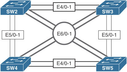
Lab 2: Configuring EtherChannels
This lab should be conducted on the Enterprise POD.
Task 1
Configure the hostname of the switches based on the provided diagram. Ensure that all the ports of these four switches are in shutdown mode. Configure these four switches in a VTP domain called TST.
Task 2
Configure ports E4/0 and E4/1 on SW2 and SW3 as trunk links, using an industry-standard protocol. These links should appear to Spanning Tree Protocol as a single link. If one of the links fails, the traffic should use the other link, without any interruption. The ports on SW2 should be configured such that they only respond to PAgP packets and never start the negotiation process.
Task 3
Configure ports E5/0 and E5/1 on SW2 and SW4 as trunk links, using an industry-standard protocol. These links should appear to Spanning Tree Protocol as a single link. If one of the links fails, the traffic should use the other link, without any interruption. These ports should not negotiate an etherchannel by exchanging LACP or PAgP protocols to accomplish this task.
Task 4
Ensure that all the EtherChannels created on SW2 are load balanced based on the destination MAC address.
Task 5
Configure ports E6/0 and E6/1 on SW3 and SW4 as a single Layer 3 link; SW3 should be configured with the IP address 34.1.1.3/24, and SW4 should be configured with the IP address 34.1.1.4/24. These ports should not negotiate LACP or PAgP.
Task 6
Erase the startup configuration and vlan.dat files before proceeding to the next lab.
Lab 3: Introducing Spanning Tree Protocol
This section is designed to teach basic to advanced concepts of Spanning Tree Protocol-.
It utilizes a common topology over which each version of Spanning Tree Protocol is configured with a given set of requirements and restraints. The requirements and restraints are engineered to explain the behaviors of each version of Spanning Tree Protocol, highlighting the important limitations and enhancements of each feature.
This lab is entirely focused on Spanning Tree Protocol technologies and assumes basic knowledge of the following:
Trunking configuration
VLAN configuration and usage
Layer 2 link aggregation
IP address configuration
Basic IP connectivity testing
Note
The solutions provided in this lab are not all inclusive. There may be many ways to solve each task. All alternate solutions are acceptable, provided that they do not violate previous restraints or tasks.
802.1D Per-VLAN Spanning Tree Protocol
This lab should be conducted on the Mock Rack.
Initial Lab Setup

Task 1
Change the hostname on each switch to SW#, where # is the number of the switch (for example, Switch 1 = SW1).
Task 2
Ensure that only the following ports on the switches are in an up/up state:
SW1
E2/1-2
E3/1-2
SW2
E1/1-2
E3/1-2
E4/1-2
E5/1-2
SW3
E1/1-2
E2/1-2
E4/1-2
E5/1-2
SW4
E2/1-2
E3/1-2
E6/1-2
SW5
E2/1-2
E3/1-2
E6/1-2
SW6
E4/1-2
E5/1-2
Task 3
Configure VLANs 10, 20, 30, and 40 on each switch, using any method.
Task 4
Configure trunk ports on all up/up interfaces.
Configuration Tasks: 802.1D
Before getting into the tasks, it helps to review the basic operation of Spanning Tree Protocol and some of the terms that will be used throughout the solution guide. These concepts will be fleshed out more throughout the guide.
802.1D Spanning Tree Protocol is the protocol that is run between switches used to prevent Layer 2 bridging loops. Loops can form in Layer 2 networks because the Layer 2 Ethernet frame format does not contain any maximum hop count limitation, such as the TTL field in the IP header. This omission of maximum hop count means a single Ethernet frame can be forwarded infinitely throughout a switched network. This is particularly dangerous when the frame being forwarded is a broadcast frame.
Switches are called transparent bridges because they abstract the physical network design from the end stations connecting to the LAN. In the past, all stations connected to a Layer 2 LAN were physically connected to the same physical electrical bus via a repeater. Only one station could speak on the segment at a time, and all stations were considered directly connected. This setup was called a single collision domain because there was a possibility that two stations would transmit at the same time, and those transmissions could collide.
Later, bridges came about that allowed intelligent learning. An ethernet Bridge would be used to combine two Layer 2 network segments into a single Layer 2 network. Bridges learned MAC addresses and only forwarded traffic between the two network segments when necessary. This operation was transparent to the end stations, because as far as the stations could detect, they were directly connected to the remote stations they were communicating with. The ethernet bridge in this way creates two separate collision domains.
An ethernet switch is basically a multiport bridge. Instead of learning MAC addresses only on two ports, a switch learns MAC addresses on all ports and forwards traffic based on destination MAC addresses to destination ports. If two ethernet frames are destined to the same port, the switch will buffer one frame while forwarding the other. Because not all traffic forwarded across the LAN segment is repeated to all ports, the switch achieves a single collision domain between each port on the switch and the stations connected to those ports.
For the switch to do this, it must first learn which MAC addresses are reachable off its various ports. To do so, the switch reads the source MAC address of all frames it receives and records it associated to the receiving port in a MAC address table, also called a Content Addressable Memory or CAM table. The switch switches traffic between ports by performing a lookup in the CAM table based on the destination MAC address of the ethernet frames. Through this, known unicast traffic can be forwarded only out the port where the intended station exists.
The problem arises when a switch receives a frame destined to a MAC address it has not learned. The switch cannot drop the frame because that would break the LAN communication. Instead, it floods the frame out all ports in the same VLAN on the switch (including trunk ports that carry those VLANs) except the port on which it initially received the frame. This process, known as unknown unicast flooding, can cause a loop condition in the switched network with broadcast frames.
Broadcast frames are frames that are intended to be received by all stations. They are sent to the well-known broadcast destination MAC address FFFF.FFFF.FFFF. When a switch encounters a broadcast frame, it performs unknown-unicast-type flooding for the frame in question. It sends the traffic out all interfaces except the interface on which it was received. The switch does this because the broadcast MAC address FFFF.FFFF.FFFF will never be the source of an ethernet frame. Because it is never the source of an ethernet frame, the switch will never associate the broadcast MAC address with a receiving port in its CAM table, triggering the unknown unicast flooding behavior.
If there are redundant links in a multi-switch environment, where the chain of interconnected links leads back to the switch that originally forwarded the broadcast traffic, a broadcast storm occurs. In a broadcast storm, each receiving switch performs the same unknown-unicast-type flooding on the broadcast packet. The broadcast packet is therefore regenerated and looped endlessly throughout the switched network. This leads to high CPU utilization on the switches and can quickly bring down the entire Layer 2 network.
Spanning Tree Protocol converts a switched network into a shortest-path tree. This tree is constructed by designating a switch as the root of the tree, called the root bridge. The root bridge is the only bridge in which all of the ports are considered designated ports. A designated port is a port that is responsible for relaying spanning-tree-related messages downstream from the root bridge to other leaf switches. From the root bridge’s perspective, all other switches are downstream from it, and thus it should be designated on all of its ports.
All non-root switches elect a single port to become their root port. The root port is the port that the switch uses to reach the root bridge. This port also receives spanning-tree-related messages on the shortest-path tree to be relayed out all other designated ports on the switch.
Finally, redundant links in the network are put into a blocking state. So-called blocking ports are ports that receive BPDUs from a designated port that is not on the shortest-path tree. In other words, they are alternate looped paths to the root bridge that are longer than the path used by the root port. Blocking ports do not send BPDUs in traditional Spanning Tree Protocol; instead, a blocking port receives a constant flow of BPDUs from the neighboring designated port.
Through this system of designated, root, and blocking ports, STP creates a loop-free network. Broadcast frames and frames undergoing unknown unicast flooding travel the shortest path from leaf switch to root switch and are blocked (dropped) on redundant links.
Task 1
Configure all switches to run 802.1D Spanning Tree Protocol.
Task 2
Ensure that SW1 is the root for every VLAN.
Task 3
Ensure that all switches wait a total of 10 seconds in the listening and learning states before moving a port to forwarding.
Task 4
Ensure that if the current root bridge fails, SW2 becomes the new root bridge for all VLANs.
Task 5
Ensure that SW2’s and SW3’s E1/2 interface is used as the root port for all VLANs. Do not modify cost to achieve this.
Task 6
Ensure that SW5 uses its E3/1 port as the root port for VLANs 10 and 30. Do not modify SW2 to achieve this.
Task 7
Ensure that SW4 uses its E3/1 port as root port for VLANs 20 and 40. Do not modify SW3 to achieve this.
Task 8
Ensure that interfaces connected to non-switch hosts come online immediately.
If SW4 or SW5 detects a switch on these ports when they first come online, they should process the BPDUs normally. Otherwise, it should not process received BPDUs.
If SW6 detects a switch on one of these ports, it should disable the port.
Task 9
Ensure that SW6 is able to fully utilize redundant links between neighboring switches. Use a Cisco-specific approach to solve this.
Task 10
Ensure that SW6’s interface toward SW5 is used as the root port for all VLANs. If the link between SW5 and SW6 goes down, SW6 should immediately switch to using its link toward SW4.
Task 11
Ensure that SW3’s interfaces is designated on the SW2/SW3 link for all VLANs.
Task 12
Ensure that SW4 and SW5 can recover from an indirect link failure within 10 seconds. Do not modify spanning-tree timers.
Task 13
Ensure that SW2 only allows its ports toward SW1 to become root ports.
Note
Do not forget to reset the switch configurations to initial configurations upon completing this exercise.
802.1w Per-VLAN Rapid Spanning Tree Protocol
So far, we have explored the processes and functionality of traditional Spanning Tree Protocol (also known as 802.1D). The original intent of 802.1D was to ensure that loop-free paths exist in a Layer 2 switched network where redundant links are utilized. 802.1D in its base form accomplishes this goal, but it does so at a price: convergence time. 802.1D utilizes timer-based convergence mechanics, which means ports must receive and evaluate BPDUs to determine the root bridge.
The winning BPDU is stored by each port and relayed out all designated ports on the switch until it is refreshed by the reception of the same BPDU on one of the switch’s non-designated (blocking or root) ports. If a port does not receive a BPDU within the Max Age time, the BPDU is aged out, and the topology reconverges. Furthermore, a port that transitions from blocking to forwarding must first pass through listening and learning states.
The entire convergence process for 802.1D, with default timers, can take up to 50 seconds (20 seconds for Max Age time and 30 seconds for transitioning between listening and learning states). As mentioned earlier in the lab, this is a considerable amount of downtime for a modern network. It interferes with host operations such as acquiring a network address to use for data communication.
Recognizing this inefficiency, the IEEE developed the 802.1w standard, which is also called the Rapid Spanning Tree Protocol, or RSTP. The goal of RSTP is to drastically reduce the amount of time it takes a network to converge during a convergence event and whenever a switch is newly joined to a network. To do so, RSTP makes a few changes to the 802.1D mechanics:
BPDUs are sent by all switches independently of reception of the root bridge’s BPDU.
Listening and learning states are combined into a single learning state.
Port roles more clearly define what function a specific port plays in the network.
Timer-based convergence is replaced by a proposal/agreement process.
In 802.1D, switches do not originate BPDUs. Instead, they relay the received superior BPDU from their root port out their designated ports. This superior BPDU is first originated by the root bridge and acts as the heartbeat of the spanning tree. 802.1w modifies this behavior. All RSTP-compliant switches generate their best stored BPDUs out all of their designated ports at each hello interval, regardless of whether or not one was received on the root ports. This transforms the BPDU from being a measurement of the activity of the root bridge to being a keepalive between two bridges.
This modification of BPDU generation means RSTP can determine if a neighboring switch is active, based on when it last received a BPDU from the neighboring switch. If three Hello intervals of BPDUs are missed (2-second intervals, for 6 seconds total), the switch can immediately act. For blocking ports, that action is to become designated and send its own BPDU. Thus, in order for a blocking port to remain in the blocking state, it must continue to receive superior BPDUs from its upstream designated port.
In addition, the port states were revised. As mentioned earlier in 802.1D, there is little difference between a port that is blocking and a port that is listening or learning. In each of these states, one of three actions is being performed:
The port is not forwarding traffic (that is, it is discarding traffic).
The port is learning about the STP topology while not forwarding traffic.
The port is learning MAC addresses while not forwarding traffic.
The first two actions correspond to the port refusing to process data frames even to the point where MAC addresses are not being learned over the ports. Instead, state information about the spanning-tree topology is being evaluated. These two functions fall within the purview of the blocking and listening states of the original 802.1D. In 802.1w, they are combined into a simple discarding state to signify that data traffic is being discarded while spanning-tree BPDUs are still being processed. The last point corresponds to the switch processing MAC address information to build MAC address tables on the interfaces—a function of the learning state. This function was deemed necessary and has been retained as the learning state in RSTP.
With these modifications, RSTP possesses only three states: discarding, learning, and forwarding. These states describe what the port is actively doing but do not describe what function in the spanning-tree topology these ports serve. This distinction is necessary to allow rapid convergence in special circumstances. For this, RSTP utilizes unused fields in the 802.1D BPDU (the flags field) to carry the port state and new port roles describing both what action the port is taking and what role that port has in the spanning-tree topology.
The port roles are:
Root: The port that receives the best BPDU of all BPDUs received by the local switch
Designated: The port that sends the best BPDU on its LAN segment
Alternate: The port that receives a superior BPDU on the LAN segment; it is a potential replacement for the root port
Backup: The port that receives the superior BPDU of the local switch’s own designated port; it is a potential replacement for the switch’s own designated port
Of all of the states, root and designated are the same and correspond to the root and designated states in 802.1D. Alternate and backup ports are synonymous with blocking ports in 802.1D, but their roles more clearly define where the port lies in the spanning tree. An alternate port is a port that receives a superior BPDU from another bridge that is not the best BPDU the switch has heard. Such ports provide alternative paths to the current root bridge.
A backup port is a port that is self-looped back to the sending local switch. This port could be connected to the same Layer 2 segment that does not speak Spanning Tree Protocol. For example, if a switch is connected to a set of hosts through a hub, the hub echoes all received frames out all ports except the port on which the frames were originally received. For redundancy, the switch could connect to the hub through two ports. If such a situation occurs, the BPDU sent by the switch on port A connected to the hub would be echoed and received on port B, connected to the same hub. If port A is determined to have the superior BPDU, port B would have the backup role because it provides a redundant path to a LAN segment that does not lead back to the root bridge.
A port in 802.1w can be in any mixture of states and roles. For instance, a port can be in the designated discarding role/state, which means it is a port that the switch believes should be designated but has not transitioned to forwarding. This fact is important for RSTP’s convergence algorithm.
In 802.1D, convergence is based on a timer-driven state machine. When a switch comes online, it sends BPDUs claiming to be root. When it receives a superior BPDU, the ports must transition from blocking, to listening, to learning, and finally to forwarding, based on the Forward Delay timer (which defaults to 15 seconds, for 30 seconds total). If a switch were to lose connection to the root port, it would announce itself as root toward its neighbors. The neighbors would ignore this information for the Max Age period (which is 20 seconds by default) before reacting to the topology change. The goal is to allow the network to converge before a port is placed into the forwarding state.
802.1w does not use the same process as 802.1D but uses a newer proposal and agreement process that goes as such:
A new link port on a switch tries to move from the blocking state to the forwarding state.
The port receives a superior BPDU from the root bridge.
All other non-edge ports are blocked on the local switch.
Once all other switch ports are blocked, the local switch authorizes the root switch to put its port into the forwarding state.
The same process occurs on all of the local switch’s remaining non-edge ports.
In step 1, the new link initializes in the designated discarding state. It exchanges BPDUs with the current root’s port (which is also in the designated discarding state). During this time, both switches send a BPDU with the proposal bit set as an indication that they want their ports to become the designated port on the segment. Upon receipt of the superior BPDU at step 2, the local switch knows where its root port lies.
In step 3, the switch must ensure no loops can occur in the network based on this new information. To do so, it places all of its non-edge ports into the discarding state; this is called synchronization. Throughout this process, the root switch’s port is still in the designated discarding state.
At step 4, the local switch tells the root switch, through a BPDU with the agreement flag set, that the root switch’s port can be moved to the designated forwarding state. This happens because the local switch has blocked all of its other non-edge ports, preventing any bridging loops.
At step 5, the local switch sends a BPDU with the proposal bit set out all of its remaining designated discarding ports to start the rapid convergence process with other potential spanning-tree bridges downstream from the root. Step 5 repeats the proposal/agreement process with each switch to which the local switch has a direct connection. The same process occurs: The switches exchange proposal BPDUs, the losing switch enters the synchronization state, and it informs the designated switch it can move its port to the designated forwarding state. In this way, the synchronization process flows downstream from the root to the edge of the network.
This process relies heavily on the switch determining which ports are edge ports and which are non-edge ports. RSTP keeps track of this by assigning an edge variable and link type status to each switch port. The edge variable indicates whether or not the port leads to an end host or sits at the edge of the network. Such ports do not connect to other switches and should not receive BPDUs. If an edge port receives a BPDU, it loses its edge status. Edge ports are allowed to immediately transition to a forwarding state; this is similar to the spanning-tree PortFast feature.
Link type refers to whether or not the switch port can use rapid transitions, as previously indicated. There are two link types: point-to-point and shared. A point-to-point link is connected to exactly one other RSTP-compliant switch. A shared port is connected to a shared LAN segment that utilizes hubs or repeaters and cannot transition rapidly, as in the previous proposal agreement process.
Switches attempt to detect link type by using the duplex setting of the interface: Half-duplex is considered shared, and full-duplex is considered point-to-point.
802.1w also achieves rapid convergence by modifying what constitutes a topology change in the network. In 802.1D, loss of a port or a port transitioning to blocking is considered a topology change event. In 802.1w, only a non-edge (blocking or alternate) port transitioning to the forwarding state generates a topology change event. The reason is that the new non-edge port offers a new path in the network, and the remaining switches should synchronize their MAC address tables accordingly to reflect the change. The TC-while timer is started on the switch initiating the topology change. During this time, the switch sends BPDUs with the TC flag set out all of its designated and root ports.
Switches that receive these BPDUs immediately age out all MAC addresses on all ports except where the TC BPDU was received. This mechanism allows rapid transition of the topology because TC BPDUs are originated by the switch experiencing the topology change event and are not initiated by the root bridge, as is the case in 802.1D.
Finally, because BPDUs are necessary for a blocking port to remain blocking, if a blocking port receives an inferior BPDU, it can react immediately to the information. This is in contrast to the 802.1D specification, which requires the stored BPDU on a port to age out before the switch converges the topology. In 802.1w, the switch receiving the inferior BPDU can infer that a topology change event has occurred somewhere in the network.
If a functioning root port exists on the switch receiving an inferior BPDU, it can simply respond with a proposal BPDU on its formerly blocking port, asking to be set to designated. This allows the failed switch to recover rapidly. If there is no functioning root port (meaning the inferior BPDU was received on a root port), the switch can assume that it should be the new root switch and indicates that with all of its remaining, now downstream, neighbors.
These are the key enhancements to 802.1D built into 802.1w. Some of them may sound familiar as they relate to many of the Cisco enhancement features to 802.1D, such as PortFast and Backbone Fast. The following lab demonstrates these enhancement features of 802.1w and contrasts them with their 802.1D equivalents.

This lab should be conducted on the Mock Rack.
Initial Configuration:
Task 1
Change the hostname on each switch to SW#, where # is the number of the switch (for example, Switch 1 = SW1).
Task 2
Ensure that only the following ports on the switches are in an up/up state:
SW1
E2/1-2
E3/1-2
SW2
E1/1-2
E3/1-2
E4/1-2
E5/1-2
SW3
E1/1-2
E2/1-2
E4/1-2
E5/1-2
SW4
E2/1-2
E3/1-2
E6/1-2
SW5
E2/1-2
E3/1-2
E6/1-2
SW6
E4/1-2
E5/1-2
Task 3
Configure VLANs 10, 20, 30, and 40 on each switch, using any method.
Task 4
Configure trunk ports on all up/up interfaces.
802.1w Configuration Tasks
Task 1
Configure all switches to run 802.1w Rapid Spanning Tree Protocol.
Task 2
Ensure that SW1 is the root for all VLANs.
Task 3
Ensure that if the current root bridge fails, SW2 becomes the new root for all VLANs.
Task 4
Ensure that SW2’s and SW3’s E1/2 interface is used as the root port for all VLANs. Do not modify cost to achieve this.
Task 5
Ensure that SW5 uses the following ports as root:
E2/1 for VLAN 10
E2/2 for VLAN 20
E3/1 for VLAN 30
E3/2 for VLAN 40
Do not modify SW5 to achieve any of this.
Task 6
Ensure that SW4 uses its E3/1 port as the root port for VLAN 20.
Task 7
Ensure that RSTP features are enabled on all ports.
Task 8
Ensure that interfaces connected to non-switch hosts come online immediately.
If SW4 or SW5 detects a switch on these ports when it first comes online, it should process the BPDUs normally. Otherwise, it should not process received BPDUs.
If SW6 detects a switch on one of these ports, it should disable the port.
Task 9
Ensure that SW6’s links toward SW5 are used as the root port for all VLANs except VLAN 10. If the link between SW5 and SW6 goes down, SW6 should immediately switch to using one of its links toward SW4 as the single root port.
Task 10
Ensure that SW4 and SW5 can recover from an indirect link failure within 10 seconds. Do not modify the spanning-tree timers.
One of the major drawbacks of 802.1D spanning tree was the timer-based convergence mechanisms. If a designated bridge loses its connection to the root, it will begin advertising itself as the root bridge to all of its connected ports. A downstream port in the blocking state would receive these inferior BPDUs. In 802.1D, the blocking port would completely ignore the information until the stored BPDU from the real root on that blocking port expires (in 20 seconds, based on the default Max Age timer). Then the switch signals a topology change event, and the port transitions to the forwarding state. The entire process can take up to 50 seconds with default timers.
The Cisco Backbone Fast feature was created to help this process by utilizing the RLQ protocol when a blocking port suddenly starts receiving inferior BPDUs. The RLQ messages are sent out in order to determine if a path to the root exists on the switch. If a path is found, the previously blocked port can bypass the Max Age timer and begin the transition to the forwarding state, cutting 20 seconds of convergence time.
RSTP incorporates this function through its behavior of immediately accepting inferior BPDUs that are received on a discarding port. An inferior BPDU being received on a discarding port signifies that a topology change has occurred somewhere in the network. Either the current root has failed and the local switch has stale information or the upstream designated bridge has lost its connection to the root. In either case, the spanning-tree topology needs to reconverge and can do so rapidly by using the proposal/agreement processes.
Since this feature is built into RSTP, there is no configuration needed to accomplish this task.
Note
Do not forget to reset the switch configurations to initial configurations upon completing this exercise.
802.1s Multiple Spanning Tree Protocol
This lab should be conducted on the Mock Rack.
Initial Configuration:
Task 1
Change the hostname on each switch to SW#, where # is the number of the switch (for example, Switch 1 = SW1).
Task 2
Ensure that only the following ports on the switches are in an up/up state:
SW1
E2/1-2
E3/1-2
SW2
E1/1-2
E3/1-2
E4/1-2
E5/1-2
SW3
E1/1-2
E2/1-2
E4/1-2
E5/1-2
SW4
E2/1-2
E3/1-2
E6/1-2
SW5
E2/1-2
E3/1-2
E6/1-2
SW6
E4/1-2
E5/1-2
Task 3
Configure VLANs 10, 20, 30, and 40 on each switch, using any method.
Task 4
Configure trunk ports on all up/up interfaces.
Let’s Explore 802.1s
One of the major drawbacks to spanning tree, be it the 802.1D Spanning Tree Protocol or RSTP, is the fact that redundant links are blocked in the network, making their bandwidth useless unless a failover event occurs. Cisco alleviated this impact by implementing PVST/+ and PVRST/+, which allow administrators to load balance individual VLANs on trunk links to better utilize the bandwidth.
The issue with this approach is that the switch must calculate a separate spanning tree for each VLAN independently. As the total number of VLANs grows, the switch spends more processor cycles calculating the spanning-tree topology. This is inefficient as the total number of possible spanning-tree topologies is limited by the total number of switches and links in the network. If there are only three switches in the network, then there are effectively only three total topologies that can exist: one topology with each switch as the root of the spanning tree. If there are a total of four VLANs in the same sample network, it is reasonable to say that the fourth VLAN spanning-tree calculation yields a redundant result to one of the previous three.
The IEEE 802.1s Multiple Spanning Tree Protocol (MST) standard mitigates this by providing a standards-based way to run different instances of Spanning Tree Protocol on a single switch. Instead of running a single instance for each VLAN, the administrator can define the instances of Spanning Tree Protocol that will be run and their parameters, such as priority and costs. Multiple VLANs are mapped to the configured instances, allowing one instance to represent one or many VLANs.
With this construct, an administrator can group together VLANs with similar pathing requirements in a single instance rather than tuning individual VLAN-specific spanning-tree instance settings. It is even possible to map all VLANs to a single instance and reduce spanning-tree processing overhead for all VLANs. Doing this reduces the computational load on the switches in the network.
The most noticeable way a switch saves computational cycles is through MST’s use of a single BPDU for all instances. Instead of explicitly sending a BPDU for each VLAN or each instance containing VLAN-to-instance mapping information, MST exchanges a single BPDU. This BPDU contains information about the root bridge and special M-records. These M-records carry the spanning-tree topology information for all instances configured on the switch.
A switch running MST must be explicitly configured with the VLAN-to-instance mapping in its MST configuration. The MST configuration first gives the MST process a name. This process name is similar to the EIGRP autonomous system number. Then, the process is explicitly given a revision number. Finally, the VLAN-to-instance mapping is configured.
Note
Unlike with EIGRP, there can be only one MST process running multiple instances at a time on a switch. Cisco documentation calls the MST process an MST instance, but for clarity between MST instances that have VLANs mapped to them, the term process is used in this lab.
In order to operate, an MST network needs to be configured with the instances that exist in the network and what VLANs are mapped to those instances. If, for example, instance 1 on SWA contains VLAN 1 but instance 10 on SWB contains VLAN 1, SWA and SWB could come to different conclusions about whether or not the port is forwarding or blocking for both VLANs. However, because no explicit VLAN-to-Instance mapping information is carried between switches, there is no way for two switches to know whether or not they are configured similarly for MST operation.
MST validates VLAN-to-instance mapping consistency between two bridges by including the MST process, the revision number, and a digest of the MST VLAN-to-instance mapping table in the BPDU. If the received BPDU matches a switch’s internal configuration, the switch knows it can trust the information contained in the M-records of the BPDU. The set of switches in a network that all have matching MST process names, revision numbers, and VLAN-to-instance mapping tables is called an MST region. Multiple MST regions can exist in a network. Topology changes in one region do not affect other regions. Also, each region builds an internal spanning tree separately as well as cooperatively (between neighboring regions) with other regions to form one loop-free path throughout the entire switched network.
Within a region, there always exists MST instance 0, which is called IST0. This instance is the only instance that interacts with other regions and is the instance to which all VLANs are initially mapped when MST is first enabled on a switch. IST0 elects a root bridge called the IST0 root. A non-root switch calculates a loop-free path from itself to the IST0 root. This ensures that no matter how many instances are added or VLANs are moved around, there is always at least one loop-free path in the MST topology.
Switches exchange IST0 BPDUs that contain the M-records for all other instances in the MST region. Using these records, independent spanning-tree topologies can be calculated for each instance.
IST0 and M-records help create a loop-free path within an MST region. MST uses a separate process to help negotiate a loop-free path between different MST regions. Switches that connect to neighboring switches in different regions are called MST boundary switches. The specific port that the local switch shares with the remote neighboring switch in a different region is called the boundary port. On boundary ports, MST only exchanges IST0 BPDU information. This makes sense because IST0 always exists within the MST region and is guaranteed to be loop free at all times. The receiving switch compares the IST0 bridge information to determine if it is superior or inferior to its own IST0 BPDU. This spanning tree running between regions is called the common spanning tree, or CST.
It helps at this point to consider two MST regions as single switches. Because the boundary switches hide the internal M-record topology from switches in different MST regions, the topology becomes very simple from the receiving switch’s perspective. Because the receiving switch cannot ensure that VLANs are mapped to the same instances as its own, the receiving switch must make a blocking/forwarding decision on its boundary port for all VLANs. This is the only way to ensure a loop-free path to the remote MST region. The MST boundary switches only compare the IST0 information received from other MST boundary switches. The boundary switches analyze this information and make forwarding or discarding decisions for all VLANs on the boundary ports.
MST interacts with regular 802.1D spanning-tree regions in a similar way. A boundary switch compares a received BPDU with its own IST0 BPDU to make a forwarding or discarding decision for all VLANs on the boundary port. This process ensures that redundant inter-region links are blocked between regions and not internally within a specific region—in the same way a switch blocks ports between switches and not links within the switch itself.
MST interacts with PVST regions a bit differently. This interaction is explained further later on in this solution guide.
Task 1
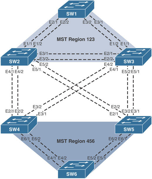
Configure all the switches to utilize the following spanning-tree configuration for SW1, SW2, and SW3:
MST is the operational mode.
The region name is 123.
The revision number is 1.
Configure the following instance-to-VLAN mappings:
Instance 1: VLANs 10–19
Instance 2: VLANs 20–29
Instance 3: VLANs 30–39
Instance 4: VLANs 40–49
Task 2
Configure all the switches to utilize the following spanning-tree configuration for SW4, SW5, and SW6:
MST is the operational mode.
The region name is 456.
The revision number is 1.
Configure the following instance-to-VLAN mappings:
Instance 1: VLAN 10
Instance 2: VLAN 20
Instance 3: VLAN 30
Instance 4: VLAN 40
Task 3
Ensure that SW1 is the root for the entire topology.
Task 4
Configure Region 123 as follows:
SW1 should be the IST root for Instances 1 and 4.
SW2 should be the IST root for Instance 2.
SW3 should be the IST root for Instance 3.
Configure Region 456 as follows:
SW6 should be the IST root for all instances except Instance 0.
SW5 should be the regional root.