Chapter 7. Scaling BGP
The following topics are covered in this chapter:
![]() Impact of growing Internet routing tables
Impact of growing Internet routing tables
![]() Scaling Internet table on various Cisco platforms
Scaling Internet table on various Cisco platforms
![]() Scaling Border Gateway Protocol (BGP) functions
Scaling Border Gateway Protocol (BGP) functions
![]() Scaling BGP with route reflectors and confederations
Scaling BGP with route reflectors and confederations
The Impact of Growing Internet Routing Tables
The Internet routing table has seen an inexorable growth since early 1990s, at a rate that has at the very least doubled in size each year. With such expansion, it has been a challenge for various vendors as well as ISPs to keep upgrading their platforms to meet the increasing needs. The requirements for maintaining the Internet routing table has long been an area of discussion and research, including the speed of transmission systems, the switching capacity of routers and switches, routing convergence, and more importantly, stability of the routing system.
The number of entries in the Internet routing table has steadily grown and reached the 256,000 routes milestone as per the Classless Inter-Domain Routing (CIDR) report. August 8, 2014, marked another milestone when the Internet routing table passed 512,000 routes. It was around that time, because of the Ternary Content-Addressable Memory (TCAM) size limitations, many router platforms required upgrading or reconfiguration to cope with the increased routing table size. As of November 2015, the CIDR report shows that the Internet routing table is nearing 581K routes. Figure 7-1 shows the graph of the growing IPv4 Internet routing table over the years. The graph plots the data from June 1988 to November 2015. Notice that the graph has been continuously showing a steep growth.

Note
Currently, the IPv4 Internet routing table is holding over 638K prefixes.
Because of this dramatic increase, there are no IPv4 addresses that can be allocated. In fact, the American Registry for Internet Numbers (ARIN)—the regional authority for North America that distributes IP addresses, officially announced on September 24, 2015, that its general IPv4 address pool was depleted. There are some Regional Internet Registries (RIRs) that still have their IPv4 address pool. Sooner or later, those will get depleted as well. Because of this limitation, the ISPs have started upgrading their networks to completely support IPv6 or function in dual-stack mode. Because the IPv6 addresses have 128 bits, it has a bigger address space. Many enterprises are now developing applications to support IPv6 addresses or dual-stack capabilities so that they don’t have to migrate their applications or redesign them from scratch.
Because of the rapidly growing Internet table, there is a rapid increase in the IPv6 Internet routing table as well. The active IPv6 BGP entries have crossed the 27,000 prefixes mark. The increase in IPv6 addresses also poses a great challenge to resource requirements because the IPv6 prefixes need more memory and TCAM space because of the 128-bit address space. They require more CPU resources as compared to IPv4 prefixes for the same reason. Figure 7-2 shows the IPv6 Internet routing table growth over the past few years.

There has also been a massive increase in the assigned autonomous system (AS) numbers. The total of assigned AS numbers, both 2-byte autonomous system number (ASN) and 4-byte ASN, has already crossed 82,000 at the time of writing. The Internet routing table sees an average of ~2.41 prefixes per BGP update and an average of 2.56 BGP update messages per second. The biggest challenge that the growing Internet poses today is the need for better CPU and higher memory.
Scaling Internet Table on Various Cisco Platforms
Not every Cisco platform (router/switch) is capable of handling the Internet routing table. Only a few routers can handle such a large number of prefixes. Even if certain routers exhaust their resources, they can still be tweaked to meet the present Internet routing table requirements.
Not many options can be controlled in a scaled network environment. The two choices are to either buy a router with more routing table capacity or design the network properly.
Buying a new router means upgrading a device which has more powerful CPU and memory to accommodate the present and near-future needs. But as the network grows, the demand for more memory and CPU resources will increase, and the device will again have to be replaced. The better option is to make proper use of the technology and redesign the network to make proper use of the available resources. Although a bigger router may still be required, it will sustain in the network for a longer period of time.
Often there is a discussion of how much memory is required to hold the Internet routing table, and which router should be used as a route reflector (RR). The answer is—it depends. Earlier, a Cisco 7200 series router with 512 MB Dynamic Random Access Memory (DRAM) was sufficient for holding the Internet routing table, but with the size of the routing table, not anymore. On top of that, many organizations now have peering with two ISPs to maintain redundancy. This doubles the memory requirement on the router.
The Cisco 6500 series or Cisco 7600 series hit the ternary content addressable memory (TCAM) limitation with the default configuration, but the TCAM can be tweaked to hold the Internet routes. Only the SUP720-3BXL or SUP720-3CXL Supervisor cards on Cisco 6500 or RSP720-3BXL or RSP720-3CXL supervisor cards on Cisco 7600 are capable of holding up to 1,000,000 IPv4 routes. The non-XL versions do not support more than 256,000 IPv4 routes and are not capable of holding full Internet routing tables. It is important to note that mixing XL and non-XL cards in the chassis results in the non-XL capacity.
ASR9000 series platforms that are configured with a Typhoon-based line card are capable of holding the Internet routing table. The Trident-based line cards are not recommended for Internet routing tables. When the Trident-based line card reaches its prefix limit, the error message ‘%ROUTING-FIB-4-RSRC_LOW’ appears on the router, causing potential traffic loss on the line cards.
The Aggregation Services Router (ASR) 1000 series routers running 4 GB DRAM can scale up to 500,000 IPv4 routes, but to hold the Internet routing table, the router should be upgraded to 8 GB DRAM or a higher size DRAM to accommodate 1,000,000 routes.
On the Nexus side, Nexus7000 XL series line cards are capable of holding multiple copies of the Internet routes in the forwarding information base (FIB) along with VRF and Virtual Device Context (VDC) support. The XL series line cards are capable of holding up to 1,000,000 IPv4 routes or up to 350,000 IPv6 routes. The non-XL line cards can support only about 128,000 IPv4 or 64,000 IPv6 routes.
Cisco has a range of routers that are good choices for deploying as RRs, especially in the scenario where the provider is holding a large number of routes along with a substantial number of customers. Earlier, the Cisco 7200 series router was as good a choice as an RR. But with the increase in the Internet routing table and the faster expansion of the service provider networks, the Cisco 7200 series is out of the league. ASR1000 series or even CSR1000v (virtual router) series routers are now the preferred routers for deploying as an RR. However, based on the scale of the network and the feature requirements, the appropriate memory, route process (RP), and forwarding engine have to be chosen. Nexus devices are not really a good choice for deployment as RR for networks carrying Internet routing tables. ASR9000 series routers are recommended as Provider Edge (PE) or aggregation routers but can be used as RRs. RRs are often deployed so that they are not in the forwarding path, and thus large devices such as ASR9000 or Nexus switches do not make sense. Because of the form factor and resource capability, the ASR 1000 fits nicely as an RR.
BGP as a protocol is a victim of its own success. Being such a simple, robust, and scalable protocol, the networking community noticed a lot of opportunity to use BGP for new features from time to time. When the BGP was first developed in 1990, it was implemented only for interdomain routing, but over the years, the scalability increased with the increase in various address-families. Now BGP is not just used for IPv4 or IPv6, but also provides various features such as Multiprotocol Label Switching (MPLS) Virtual Private Network (VPN), Multicast VPN, and the like. BGP has now been expanded in data-center environments to carry Virtual Extensible LAN (VXLAN) information using VXLAN-EVPN. Table 7-1 shows the control-plane evolution with BGP between 2000 and 2014.

With so many address-families being supported, there are more challenges that BGP has to face, which include the following:
![]() More prefixes
More prefixes
![]() More BGP routers
More BGP routers
![]() Multipath
Multipath
![]() Attributes and policies
Attributes and policies
![]() More resilience
More resilience
With so many challenges, it is possible to extend the life cycle or enhance the performance of a router by focusing on scalability. It is thus very important and crucial to know how to tune BGP rather than keep upgrading routers in the network.
Scaling BGP Functions
BGP is one of the most feature-rich protocols ever developed that provides ease of routing and control using policies. Although BGP has many built-in features that can allow it to scale very well, these enhancements are not always utilized properly. This poses various concerns when BGP is deployed in a scaled environment.
BGP is a heavy protocol because it uses the most CPU and memory resources on a router. And there are many factors that explain why it keeps utilizing more and more resources. The three major factors for BGP memory consumption are as follows:
![]() Prefixes
Prefixes
![]() Paths
Paths
![]() Attributes
Attributes
BGP can hold many prefixes, and each prefix consumes some amount of memory. But when the same prefix is learned via multiple paths, that information is also maintained in the BGP table. Each path requires additional memory space. Because BGP was designed to give control to each AS to manage the flow of traffic through various attributes, each prefix can have several attributes per path. This is shown as a mathematical function:
![]() Prefixes: (O(N))
Prefixes: (O(N))
![]() Paths: (O(M × N))
Paths: (O(M × N))
![]() Attributes: (O(L × M × N))
Attributes: (O(L × M × N))
The topology in Figure 7-3 shows three paths to reach a prefix learned from router R5 on router R1.

Example 7-1 demonstrates various BGP paths with various communities and attributes. Notice that each attribute or community learned from an individual neighbor for the prefix 192.168.100.0/24 is stored in the BGP table, thereby increasing memory consumption. Three paths are available for the prefix, out of which path number 3 is chosen as the best. The various paths within the address-family can be seen using the command show bgp afi safi paths.
Example 7-1 BGP Multipath Prefix
R1# show bgp ipv4 unicast 192.168.100.0
BGP routing table entry for 192.168.100.0/24, version 35
Paths: (3 available, best #3, table default, not advertised to EBGP peer)
Advertised to update-groups:
1
Refresh Epoch 5
400 500
192.168.2.2 (metric 2) from 192.168.2.2 (192.168.2.2)
Origin IGP, metric 0, localpref 100, valid, internal
Community: internet 400:100 500:100
rx pathid: 0, tx pathid: 0
Refresh Epoch 4
300 500
10.1.13.3 from 10.1.13.3 (192.168.3.3)
Origin IGP, localpref 100, valid, external
Community: internet 300:100 500:100
rx pathid: 0, tx pathid: 0
Refresh Epoch 3
400 500
10.1.14.4 from 10.1.14.4 (192.168.4.4)
Origin IGP, localpref 100, valid, external, best
Community: 400:100 no-export
rx pathid: 0, tx pathid: 0x0
R1# show bgp ipv4 unicast paths
Address Hash Refcount Metric Path
0xCB130EC 2852 1 0 300 500 i
0xCB132E4 2889 1 0 400 500 i
0xCB1323C 2890 1 0 400 500 i
Example 7-1 showed how the memory consumption per BGP prefix depends on the number of paths, path attributes, and AS-Paths associated with it. When the prefix scale increases, the memory consumption on the router increases, and services could be impacted. It is therefore imperative to have the BGP memory tuned properly.
Tuning BGP Memory
To reduce or tune the BGP memory consumption, adjustments should be made to the three major factors leading to most BGP memory consumption as previously discussed. The various adjustments that can be made for each factor are discussed in the sections that follow.
Prefixes
BGP memory consumption becomes critical when BGP is holding a large number of prefixes or holding the Internet routing table. In most cases, not all the BGP prefixes are required to be maintained by all the routers running BGP in the network. To reduce the number of prefixes, the following actions can be taken:
![]() Aggregation
Aggregation
![]() Filtering
Filtering
![]() Partial routing table instead of full routing table
Partial routing table instead of full routing table
With the use of aggregation, multiple specific routes can be aggregated into one route. But aggregation is challenging when performed on a fully deployed running network. After the network is up and running, the complete IP addressing scheme has to be examined to execute aggregation. Aggregation is a good option for green field deployments. The green field deployments give more control on the IP addressing scheme, which makes it easier to apply aggregation.
Filtering provides control over the number of prefixes that should be maintained in the BGP table or advertised to BGP peers. BGP provides filtering based on prefix, BGP attributes, and communities. One important point to remember is that complex route filtering or route filtering applied for a large number of prefixes helps reduce the memory required but also requires additional CPU resources to apply the policy on BGP updates.
Many deployments do not require all the BGP speakers to maintain a full BGP routing table. The BGP speakers can maintain even a partial routing table, containing the most relevant and required prefixes. Such designs greatly reduce the resources being used throughout the network and increase scalability.
Managing the Internet Routing Table
If an enterprise is peering with an ISP, the ISP can advertise the full Internet routing table using BGP or a default routing table using BGP or Interior Gateway Protocol (IGP). Generally, an enterprise doesn’t need access to the complete Internet routing table. If the ISP is advertising a full Internet table, there are few ways of managing the Internet routing table:
![]() Ask the ISP to not send the whole Internet routing table by either filtering the needed routes or by advertising a default route. The enterprise should perform the route filtering as a fail-safe in case the ISP makes a mistake and sends the full Internet routing table.
Ask the ISP to not send the whole Internet routing table by either filtering the needed routes or by advertising a default route. The enterprise should perform the route filtering as a fail-safe in case the ISP makes a mistake and sends the full Internet routing table.
![]() If the ISP cannot filter the routes, filtering can be performed at the enterprise edge router for the required prefixes. This option gives more control over the Internet routing table within the network.
If the ISP cannot filter the routes, filtering can be performed at the enterprise edge router for the required prefixes. This option gives more control over the Internet routing table within the network.
![]() If resource conservation is the primary focus, ask the ISP to advertise a default route and regional ISP specific routes. This saves a lot of resources.
If resource conservation is the primary focus, ask the ISP to advertise a default route and regional ISP specific routes. This saves a lot of resources.
Figure 7-4 illustrates how using the preceding three points scales the network and consumes fewer resources. The topology has three routers: R1, Internet-GW, and ISP-RTR. The Internet-GW router is the enterprise edge router peering with the ISP router named ISP-RTR.

For the sake of understanding, only fewer routes, say 50,000 routes, are being advertised by the ISP-RTR router. Example 7-2 illustrates that the BGP memory consumption on Internet-GW router is high with the ISP router advertising the Internet routing table. But after filtering those routes and configuring a default route, the memory utilization is much better as compared to what was before.
Example 7-2 Scaling Enterprise Edge Router with Default Route
Internet-GW# show bgp ipv4 unicast summary
BGP router identifier 192.168.2.2, local AS number 65000
BGP table version is 50001, main routing table version 50001
50001 network entries using 7200144 bytes of memory
50001 path entries using 4000080 bytes of memory
5000/5000 BGP path/bestpath attribute entries using 760000 bytes of memory
5000 BGP AS-PATH entries using 225920 bytes of memory
0 BGP route-map cache entries using 0 bytes of memory
0 BGP filter-list cache entries using 0 bytes of memory
BGP using 12186296 total bytes of memory
BGP activity 170000/120000 prefixes, 200000/150000 paths, scan interval 60 secs
Neighbor V AS MsgRcvd MsgSent TblVer InQ OutQ Up/Down State/PfxRcd
10.1.23.3 4 100 5010 14 50001 0 0 00:09:26 50000
192.168.1.1 4 65000 32 5105 50001 0 0 00:24:39 1
Internet-GW(config)# route-map DENY-ALL deny 10
Internet-GW(config-route-map)# match ip address prefix-list DENY-IP
Internet-GW(config-route-map)# exit
Internet-GW(config)# ip prefix-list DENY-IP seq 5 permit 0.0.0.0/0 le 32
Internet-GW(config)# router bgp 65000
Internet-GW(config-router)# address-family ipv4 unicast
Internet-GW(config-router-af)# neighbor 10.1.23.3 route-map DENY-ALL in
Internet-GW(config-router-af)# end
Internet-GW# show bgp ipv4 unicast summary
BGP router identifier 192.168.2.2, local AS number 65000
BGP table version is 100003, main routing table version 100003
1 network entries using 144 bytes of memory
1 path entries using 80 bytes of memory
1/1 BGP path/bestpath attribute entries using 152 bytes of memory
0 BGP route-map cache entries using 0 bytes of memory
0 BGP filter-list cache entries using 0 bytes of memory
BGP using 376 total bytes of memory
BGP activity 170001/170000 prefixes, 200001/200000 paths, scan interval 60 secs
Neighbor V AS MsgRcvd MsgSent TblVer InQ OutQ Up/Down State/PfxRcd
10.1.23.3 4 100 5580 641 100002 0 0 09:37:57 0
192.168.1.1 4 65000 674 5797 100003 0 0 10:07:04 1
After the route filtering is performed and the static default route is configured toward the ISP, the command neighbor ip-address default-originate can be configured on the Internet-GW router toward the neighbor R1 to advertise the default route. This way, R1 has a path to reach the Internet.
Paths
Sometimes the BGP table carries fewer prefixes but still holds more memory because of multiple paths. A prefix can be learned via multiple paths, but only the best or multiple best paths can be installed in the routing table. To reduce the memory consumption by BGP due to multiple paths, the following solutions should be adopted:
![]() Reduce the number of peerings
Reduce the number of peerings
![]() Use RRs instead of IBGP full mesh
Use RRs instead of IBGP full mesh
Multiple BGP paths are caused by multiple BGP peers. Especially in an internal BGP (IBGP) full mesh environment, the number of BGP sessions increases exponentially, as does the number of paths. A lot of customers increase the number of IBGP neighbors to have more redundant paths, but two paths are sufficient to maintain redundancy. Increasing the number of peerings can cause scaling issues both from the perspective of the number of sessions and from the perspective of BGP memory utilization.
It is a well-known fact that IBGP needs to be in full mesh. Figure 7-5 illustrates an IBGP full-mesh topology. In an IBGP full-mesh deployment of n nodes, there are a total of n * (n - 1) / 2 IBGP sessions and (n - 1) sessions per BGP speaker.

This not only affects the scalability of an individual node or router, but it affects the whole network. To increase the scalability of IBGP network, two design approaches can be used:
![]() Confederations
Confederations
![]() Route reflectors
Route reflectors
Note
BGP route reflectors are discussed later in this chapter.
Attributes
A BGP route is a “bag” of attributes. Every BGP prefix has certain default or mandatory attributes that are assigned automatically, such as next-hop or AS-PATH or attributes that are configured manually, such as Multi-Exit Discriminator (MED), assigned by customers. Each attribute carried with the prefix contributes to the total amount of memory consumed. Along with attributes, communities—both standard and extended—add to increased memory consumption. To reduce the BGP memory consumption due to various attributes and communities, the following solutions can be adopted:
![]() Reduce the number of attributes
Reduce the number of attributes
![]() Filter standard or extended communities
Filter standard or extended communities
![]() Reduce the newer types of attributes (that is, AIGP, IBGP PE-CE)
Reduce the newer types of attributes (that is, AIGP, IBGP PE-CE)
There is no method to get rid of the default BGP attributes, but the use of other elements can be controlled. Using attributes that can make things more complex is not advantageous. For example, using MED and various MED-related CLI, such as the command bgp always-compare-med or bgp deterministic-med, may have an adverse impact on the network as described in RFC 3345 and lead to route instability or routing loop conditions. Thus the MED attribute and other related CLIs mentioned previously should be carefully configured in the network. User assigned attributes will consume more BGP memory, which can easily be avoided.
BGP community attributes make it easier to have more control over the BGP learned prefixes, both from Inter-AS and Intra-AS. Each destination can belong to multiple communities. Although there are no recommended ISP BGP communities apart from what is defined in RFC1998 or the four standard well-known communities, communities are very useful in an ISP network because it helps give control over the prefix to the customers. Communities are usually applied with route-maps. Extended communities such as Site of Origin (SOO) have specific requirements that are not always used and required, whereas standard communities provide policy-based routing.
Community attributes are numbers that represents specific meaning in the network. Based on the assigned value, certain actions are defined for the prefix in the network. As the network grows older and more mature, more communities are added over the period of time. Some of the older assigned community values lose their meaning or are not needed. But they are never touched, because network operators are afraid of breaking something in the network since they have no knowledge about those communities. Network administrators should try to reduce the number of BGP communities being used in the network. It not only makes the network much simpler to manage but also saves on network resources.
A router can receive a prefix with a community attribute attached and forward the community attached prefix to its peers, but the router controls the advertisement of the locally assigned community to another BGP peer using the command neighbor ip-address send-community. If the command is not specified, the locally assigned community is not advertised to BGP peers.
The newer features, such as IBGP PE-CE or Accumulated Interior Gateway Protocol (AIGP), introduce newer BGP attributes. When enabling IBGP between the Provider Edge (PE) and Customer Edge (CE) routers, a BGP attribute named ATTR_SET is added to the VPN prefix that allows all path attributes from the CE router to be carried across the service provider cloud. Using the AIGP metric attribute, BGP speakers receive knowledge about the end-to-end metric of all the paths. The AIGP metric attribute copies the IGP metric into BGP and helps to improve the path selection process.
Tuning BGP CPU
BGP is a heavy protocol and can consume a lot of CPU cycles. This has been detailed in Chapter 6, “Troubleshooting Platform Issues due to BGP.” But using certain features and changing certain command lines helps save a lot of CPU resources. Use the following features to improve the CPU resources:
![]() Peer-groups and templates
Peer-groups and templates
![]() BGP soft reset
BGP soft reset
![]() IOS peer groups
IOS peer groups
![]() IOS peer templates
IOS peer templates
![]() NXOS peer templates
NXOS peer templates
![]() IOS XR BGP templates
IOS XR BGP templates
IOS Peer-Groups
Peer-groups are templates that can be used to assign common policies and attributes, such as an AS number or source-interface, and the like for multiple neighbors. This saves a lot of time and effort while configuring, when multiple neighbors have the same policy. But the peer-groups were not designed to save typing. By grouping neighbors with common policy together, routers save a lot of CPU resources by creating a one-time route object and then advertising that object to multiple peers. Example 7-3 illustrates the peer-group configuration on Cisco IOS software. Notice that after the peer-group is configured and the parameters are defined for the peer-group, the network administrator only needs to add neighbors to that peer-group. This saves a lot of time to bring up new neighbors.
Example 7-3 BGP Peer-Group Configuration
R1(config)# router bgp 65530
R1(config-router)# neighbor iBGP-RRC peer-group
R1(config-router)# neighbor iBGP-RRC remote-as 65530
R1(config-router)# neighbor iBGP-RRC update-source loopback0
R1(config-router)# neighbor 192.168.2.2 peer-group iBGP-RRC
R1(config-router)# neighbor 192.168.3.3 peer-group iBGP-RRC
R1(config-router)# address-family ipv4 unicast
R1(config-router-af)# neighbor iBGP-RRC route-reflector-client
R1(config-router-af)# neighbor 192.168.2.2 activate
R1(config-router-af)# neighbor 192.168.3.3 activate
IOS XR BGP Templates
There is no concept of peer-groups in IOS XR. IOS XR provides template support for neighbor configuration using the af-group, session-group, and neighbor-group commands. Table 7-2 states the use of these three BGP template configurations.

BGP neighbors may choose to override some of the inherited attributes from the templates. Example 7-4 illustrates the use of BGP templates on IOS XR.
Example 7-4 BGP Templates on IOS XR
RP/0/0/CPU0:R10(config)# router bgp 65530
! Configure af-group
RP/0/0/CPU0:R10(config-bgp)# af-group IPv4-AFI address-family ipv4 unicast
RP/0/0/CPU0:R10(config-bgp-afgrp)# route-reflector-client
RP/0/0/CPU0:R10(config-bgp-afgrp)# next-hop-self
RP/0/0/CPU0:R10(config-bgp-afgrp)# exit
! Configure session-group
RP/0/0/CPU0:R10(config-bgp)# session-group IPv4-SG
RP/0/0/CPU0:R10(config-bgp-sngrp)# remote-as 65530
RP/0/0/CPU0:R10(config-bgp-sngrp)# update-source loopback 0
RP/0/0/CPU0:R10(config-bgp-sngrp)# exit
! Configure neighbor-group
RP/0/0/CPU0:R10(config-bgp)# neighbor-group IBGP-GRP
RP/0/0/CPU0:R10(config-bgp-nbrgrp)# advertisement-interval 5
RP/0/0/CPU0:R10(config-bgp-nbrgrp)# exit
RP/0/0/CPU0:R10(config-bgp)# neighbor 192.168.2.2
RP/0/0/CPU0:R10(config-bgp-nbr)# use session-group IPv4-SG
RP/0/0/CPU0:R10(config-bgp-nbr)# use neighbor-group IBGP_GRP
RP/0/0/CPU0:R10(config-bgp-nbr)# address-family ipv4 unicast
RP/0/0/CPU0:R10(config-bgp-nbr-af)# use af-group IPv4-AFI
RP/0/0/CPU0:R10(config-bgp-nbr-af)# commit
NX-OS BGP Peer Templates
NX-OS uses peer templates to provide more concise peer configuration model. The NX-OS implementation of peer templates consists of three template types: peer-policy, peer-session, and peer template.
A peer-policy defines the address-family–dependent policy aspects for a peer, including inbound and outbound policy, filter-list and prefix-lists, soft-reconfiguration, and so on. A peer-session template defines “session” attributes such as transport details and session timers. Both the peer-policy and peer-session templates are inheritable; that is, a peer-policy or peer-session can inherit attributes from another peer-policy or peer-session, respectively. A peer template pulls the peer-session and peer-policy sections together to allow “cookie-cutter” neighbor definitions.
Example 7-5 illustrates peer template configurations on NX-OS.
Example 7-5 BGP Peer Templates on NX-OS
R20(config)# router bgp 65530
! Configure peer-policy template
R20(config-router)# template peer-policy PEERS-V4
R20(config-router-ptmp)# route-reflector-client
R20(config-router-ptmp)# next-hop-self
R20(config-router-ptmp)# exit
! Configure peer-session template
R20(config-router)# template peer-session PEER-DEFAULT
R20(config-router-stmp)# remote-as 65530
R20(config-router-stmp)# update-source loopback0
R20(config-router-stmp)# password cisco
R20(config-router-stmp)# exit
! Configure peer template
R20(config-router)# template peer IBGP-RRC
R20(config-router-neighbor)# inherit peer-session PEER-DEFAULT
R20(config-router-neighbor)# address-family ipv4 unicast
R20(config-router-neighbor-af)# inherit peer-policy PEERS-V4 10
R20(config-router)# neighbor 192.168.1.1
R20(config-router-neighbor)# inherit peer IBGP-RRC
R20(config-router-neighbor)# exit
BGP Peer Templates on Cisco IOS
In older versions of Cisco IOS, the peer-group configuration was used to group update messages for the peers using the BGP update groups feature. The update generation process on Cisco IOS is explained in great detail in Chapter 5, “Troubleshooting BGP Convergence.” But there were a few challenges with the peer-group configuration on the Cisco IOS software, as follows:
![]() All peer-group members had to share the same outbound policy.
All peer-group members had to share the same outbound policy.
![]() All neighbors should be part of same peer-group and address-family. Neighbors configured in different address-families cannot belong to different peer-groups.
All neighbors should be part of same peer-group and address-family. Neighbors configured in different address-families cannot belong to different peer-groups.
Such behaviors limited the scalability of neighbor configuration and reduced efficiency of the update message generation.
The separation of peer-group with the update-group generation process was introduced with BGP Dynamic Update Peer-Groups feature. The restriction of BGP neighbor configuration to outbound policy for an update-group is no longer applicable. But the peer-group configuration still retains the following limitations:
![]() A BGP neighbor can belong to only one peer-group.
A BGP neighbor can belong to only one peer-group.
![]() Neighbors belonging to different address-families cannot be part of same peer-group.
Neighbors belonging to different address-families cannot be part of same peer-group.
![]() Only one outbound policy can be configured per peer-group.
Only one outbound policy can be configured per peer-group.
Peer templates were introduced to overcome the limitations of peer-group configuration. Similar to NX-OS, the peer template configuration is inheritable and can form multiple hierarchies. There are two types of peer templates: peer-session and peer-policy.
The peer-session template allows configuring session-related parameters, whereas the peer-policy template allows for address-family–dependent configuration. Both the peer-session and peer-policy templates give more flexibility on configuring neighbors and provide faster convergence. Example 7-6 illustrates the configuration of peer-templates.
Example 7-6 BGP Peer Templates on Cisco IOS
R1(config)# router bgp 65530
! Configuring peer-session template
R1(config-router)# template peer-session IBGP-SESSION
R1(config-router-stmp)# remote-as 65530
R1(config-router-stmp)# update-source loopback0
R1(config-router-stmp)# exit
! Configuring peer-policy template
R1(config-router-stmp)# template peer-policy IBGP-NHS
R1(config-router-ptmp)# next-hop-self
R1(config-router-ptmp)# exit
R1(config-router)# template peer-policy IBGP-POLICY
R1(config-router-ptmp)# route-reflector-client
! Inheriting peer-policy NHS
R1(config-router-ptmp)# inherit peer-policy NHS 10
R1(config-router-ptmp)# exit
R1(config-router)# neighbor 192.168.2.2 inherit peer-session IBGP-SESSION
R1(config-router)# address-family ipv4 unicast
R1(config-router-af)# neighbor 192.168.2.2 activate
R1(config-router-af)# neighbor 192.168.2.2 inherit peer-policy IBGP-POLICY
Soft Reconfiguration Inbound Versus Route Refresh
BGP peers are requested for resending updates to peers when making adjustments to inbound BGP policies. BGP updates are incremental; that is, after the initial update is completed, only the changes are received. So BGP sessions are required to be reset, to request peers to send a BGP UPDATE message with all the NLRIs, so those updates can be rerun via the new filter. There are two methods to perform the session reset:
![]() Hard Reset: Dropping and reestablishing a BGP session. Can be performed by command clear bgp afi safi [* | ip-address].
Hard Reset: Dropping and reestablishing a BGP session. Can be performed by command clear bgp afi safi [* | ip-address].
![]() Soft Reset: A soft reset uses the unaltered prefixes, stored in the Adj-RIB-In table, to reconfigure and activate BGP routing tables without tearing down the BGP session.
Soft Reset: A soft reset uses the unaltered prefixes, stored in the Adj-RIB-In table, to reconfigure and activate BGP routing tables without tearing down the BGP session.
A hard reset of a BGP session is disruptive to an operational network. If a BGP session is reset repeatedly over a short period of time because of multiple changes in BGP policy, it can result in other routers in the network dampening prefixes, causing destinations to be unreachable and traffic to be black holed.
A soft reconfiguration is a traditional way to allow route policy to be applied on the inbound BGP route update. BGP soft reconfiguration is enabled by using the neighbor ip-address soft-reconfiguration inbound configuration. When configured, the BGP stores an unmodified copy of all routes received from that peer at all times, even when the routing policies did not change frequently. One of the benefits of soft reconfiguration is that it helps test your filtering policies. Enabling soft reconfiguration means that the router also stores prefixes/attributes received prior to any policy application. This caused an extra overhead on memory and CPU on the router.
To manually perform a soft reset, use the command clear bgp ipv4 unicast [* | ip-address] soft [in | out]. The soft-reconfiguration feature is useful when an operator wants to know which prefixes have been sent to a router prior to the application of any inbound policy.
To overcome the challenges of soft-reconfiguration inbound configuration, BGP route refresh capability was introduced and is defined in RFC 2918. The BGP route refresh capability has a capability code of 2 and the length of 0. Using the route refresh capability, the router sends out a route refresh request to a peer to get the full table from the peer again. The advantage of route refresh capability is that no preconfiguration is needed to enable it. The ROUTE-REFRESH message is a new BGP message type, as shown in Figure 7-6.

The AFI and SAFI in the ROUTE-REFRESH message point to the address-family where the configured peer is negotiating the route refresh capability. The Reserved bits are unused and are set to 0 by the sender and ignored by the receiver.
A BGP speaker can send a ROUTE-REFRESH message only if it has received a route refresh capability from its peer. This implies that all the participating routes should support the route refresh capability. The router sends a route refresh request (REFRESH_REQ) to the peer. After the speaker receives a route refresh request, the BGP speaker readvertises to the peer the Adj-RIB-Out of the Address-Family Identifier (AFI), and Subaddress-Family Identifier (SAFI) carried in the message, to its peer. The requesting peer receives the prefixes after any outbound policy applied on the peer is executed.
The clear ip bgp ip-address in or clear bgp afi safi ip-address in command tells the peer to resend a full BGP announcement by sending a route refresh request, whereas the clear bgp afi safi ip-address out command resends a full BGP announcement to the peer, and it does not initiate a route refresh request. The route refresh capability is verified by using the show bgp afi safi neighbor ip-address command. Example 7-7 displays the route refresh capability negotiated between the two BGP peers.
Example 7-7 BGP Route-Refresh Capability
R1# show bgp ipv4 unicast neighbor 10.1.12.2
BGP neighbor is 10.1.12.2, remote AS 65530, internal link
BGP version 4, remote router ID 192.168.2.2
BGP state = Established, up for 2d03h
Neighbor sessions:
1 active, is not multisession capable (disabled)
Neighbor capabilities:
Route refresh: advertised and received(new)
Four-octets ASN Capability: advertised and received
Address family IPv4 Unicast: advertised and received
! Output omitted for brevity
Note
When the soft-reconfiguration feature is configured, the BGP route refresh capability is not used, even though the capability is negotiated. The soft-reconfiguration configuration controls the processing or initiating route refresh.
To further understand the route refresh capability, examine the flow of messages during an update request using the route refresh capability between routers in Figure 7-7.

Example 7-8 illustrates how the BGP route refresh capability works with the help of debug commands. An inbound policy is applied on the router R1 to set the community value of 100:2 for the prefixes received from R2. To view the message exchange, enable debug command debug bgp ipv4 unicast in and debug bgp ipv4 unicast update. After the debug is enabled, issue the command clear bgp ipv4 unicast ip-address in, which triggers the router to initiate a refresh request. Notice that the value highlighted in braces is the message type. The message type 5 represents the ROUTE-REFRESH message.
Example 7-8 BGP Update Using Route Refresh
R1# debug bgp ipv4 unicast in
R1# debug bgp ipv4 unicast 192.168.2.2 updates
R1(config)# route-map SET_COMM permit 10
R1(config-route-map)# set community 100:2
R1(config-route-map)# exit
R1(config)# router bgp 100
R1(config-router)# address-family ipv4 unicast
R1(config-router-af)# neighbor 192.168.2.2 route-map SET_COMM in
R1(config-router-af)# end
! Initiating Route Refresh using clear command
R1# clear bgp ipv4 unicast 192.168.2.2 in
17:46:36: BGP: 192.168.2.2 sending REFRESH_REQ(5) for afi/safi: 1/1,
refresh code is 0
17:46:36: BGP(0): 192.168.2.2 rcvd UPDATE w/ attr: nexthop 192.168.2.2,
origin i, localpref 100, metric 0
R1# debug bgp ipv4 unicast out
R1# debug bgp ipv4 unicast 192.168.1.1 updates
17:46:36: BGP: 192.168.1.1 rcvd REFRESH_REQ for afi/safi: 1/1,
refresh code is 0
17:46:36: BGP(0): (base) 192.168.1.1 send UPDATE (format) 192.168.2.2/32,
next 192.168.2.2, metric 0, path Local
Notice the refresh code 0 in Example 7-8. The value 0 indicates that BGP route refresh is being requested.
The BGP refresh request (REFRESH_REQ) is sent in one of the following cases:
![]() clear bgp afi safi [* | ip-address] in command is issued.
clear bgp afi safi [* | ip-address] in command is issued.
![]() clear bgp afi safi [* | ip-address] soft in command is issued.
clear bgp afi safi [* | ip-address] soft in command is issued.
![]() Adding or changing inbound filtering on the BGP neighbor via route-map.
Adding or changing inbound filtering on the BGP neighbor via route-map.
![]() Configuring allowas-in for the BGP neighbor.
Configuring allowas-in for the BGP neighbor.
![]() Configuring soft-reconfiguration inbound for the BGP neighbor.
Configuring soft-reconfiguration inbound for the BGP neighbor.
![]() Adding a route-target import to a VRF in MPLS VPN (for AFI/SAFI value 1/128 or 2/128).
Adding a route-target import to a VRF in MPLS VPN (for AFI/SAFI value 1/128 or 2/128).
Note
It is recommended to use soft-reconfiguration inbound only on EBGP peering whenever it is required to know what the EBGP peer previously advertised that has been filtered out. It is not recommended to configure soft-reconfiguration inbound command when there are large numbers of prefixes being learned, such as the Internet routing table over the EBGP connection.
Dynamic Refresh Update Group
To perform efficient formatting and replication, an update group mandates that the peers with the oldest table version in an update group must be processed first. This is done to allow such unprogressive peers to catch up with other peers in the update group. The behavior is achieved by processing the peers with the lowest BGP table version first until they reach the next-lowest peer’s table version from where these peers would be processed together, and so on.
Replication based on the oldest table first approach has an obvious disadvantage of introducing serialization. This becomes far more apparent whenever peers are servicing route refresh requests for large table sizes in an update group.
When the route refresh request is received from a member of an update group (typically generated by PE as part of VRF provisioning), a BGP update group resets the neighbor table version to 0. This causes an update group to process peers servicing route refresh requests until they catch up with either the latest BGP table version or the version number of the second-lowest peer. The behavior of an update group imposes an update group peer delay to process any other transient network churn after all the peers have synced up to the latest version number.
To overcome this problem, dynamic refresh update groups were introduced. The dynamic refresh update groups implement a mechanism that decouples part of the peer members so that both the route refresh peers as well as other peer members in an update group are not serialized by the update group design.
Whenever a route refresh request is received, BGP schedules a route refresh timer of 60 seconds (default to an update group) if it is not already scheduled. The refresh process is initiated at the timer expiration. After the route refresh is processed, the “refresh state” is tracked under a separate dynamic refresh update group. The refresh state handles resetting of the peer table versions in the dynamically created update group; therefore, the current peer state is not affected.
If the refresh service is in progress for the corresponding update group, any other route refresh request is queued on the route refresh timer. This ensures that at any given time, only one set of refresh requests is serviced by an update group and its peers. In other words, several route refresh requests from one peer or several peers are processed together when the BGP refresh timer expires in the new dynamic refresh update group. It is important to remember that peers in the dynamic refresh update group receive the full RIB, whereas the peers in the regular update group receive the regular BGP updates.
Figures 7-8 through 7-10 explain the difference between regular update groups and dynamic refresh update groups with an example. Figure 7-8 displays the flow of a regular update group in which the peer with the lowest BGP table version is updated until it reaches the next lowest peer table version, and then both are replicated to the next table version until all the updates are replicated.

If a route refresh request is received from a member—for example, when a new VRF is provisioned, a BGP update group resets the table version to 0, as shown in Figure 7-9. This causes an update group to process the peer servicing route refresh requests until they catch up either with the latest BGP table version or the version number of the second lowest peer in an update group.

Figure 7-10 shows that with dynamic route refresh update groups, the refresh state is tracked under a separate dynamic refresh update group. The refresh state handles the resetting of the peer table versions in a separate update group that does not affect the current peer states.

The dynamic refresh update group feature is supported starting from Cisco IOS release 12.2(33)XNE or 12.2(31)SB13. There is no special configuration required to enable dynamic refresh update groups. IOS XR already implements more structured logic for handling update generation by using update groups and subgroups.
Note
IOS XR dynamically forms subgroups, which is a subset of neighbors within an update group based on the table version approximation. The subset of neighbors in a subgroup run at the same pace with regard to sending updates. If there are some neighbors that have a distinct table version, these are decoupled to different subgroups.
The dynamic refresh update group is created when any of the following events occur:
![]() Receiving route-refresh request
Receiving route-refresh request
![]() Receiving Outbound Route Filtering (ORF) immediate request
Receiving Outbound Route Filtering (ORF) immediate request
![]() New peer establishment
New peer establishment
![]() Any outbound policy change
Any outbound policy change
![]() Reset of BGP sessions (hard reset or outbound soft reset)
Reset of BGP sessions (hard reset or outbound soft reset)
The dynamic refresh update groups are recommended for RRs, typically L3VPN RRs, which have large numbers of IBGP peers within the same update group and may receive a route refresh request from any PE peers on VRF provisioning. The feature significantly reduces BGP convergence time of stable peers for update events during servicing of route refresh requests.
Note
In case of a large scaled number of VPN prefixes, generally seen in a tier-1 VPN provider, the convergence time could be reduced to under 10 to 20 seconds from 15 to 30 minutes.
Enhanced Route Refresh Capability
The toughest challenges to troubleshoot in BGP are route inconsistencies between peers. For example, withdraw or update not advertised to a peer can lead to a traffic black-hole problem. It takes a long time for customers to know and understand the problem and fix it. When the problem is identified, the most common solution is issuing the clear ip bgp ip-address soft in command. This workaround might not resolve the problem every time.
BGP enhanced route refresh capability is a new BGP capability with new enhancements to the route refresh capability that prevents any kind of inconsistency between the BGP peers. This capability is enabled in most of the recent Cisco IOS releases. During the BGP session establishment, a router sends Enhanced Refresh Capability via BGP capabilities advertisement (BGP-CAP). The capability is advertised with capability code 70 and length 0.
The message format for enhanced route refresh capability is same as the route refresh capability with a minute difference of the value in the reserved bits, a.k.a. Status bits. The three values of the status bits are as follows:
![]() 0: Normal Route Refresh Request
0: Normal Route Refresh Request
![]() 1: Start-of-RIB Route Refresh Message (BoRR: Beginning of Route Refresh)
1: Start-of-RIB Route Refresh Message (BoRR: Beginning of Route Refresh)
![]() 2: End-of-RIB Route Refresh Message (EoRR: Ending of Route Refresh)
2: End-of-RIB Route Refresh Message (EoRR: Ending of Route Refresh)
After the enhanced route refresh capability is negotiated, the BGP peer generates route refresh Start-of-RIB (SOR) before advertisement of Adj-Rib-Out and generates route refresh End-of-RIB (EOR) post advertisement of Adj-RIB-Out. A BGP speaker receiving an EOR message from its peer cleans up all the routes that were not readvertised as part of the route refresh response by the peer using the route refresh SOR. The route refresh EOR assists BGP to clear out any stale entries in the BGP table.
There might still be situations when continuous route churns occur in the network. During the same time, enhanced refresh EOR is not advertised by the peer, and the stale routes are cleaned up after expiration of the refresh EOR stale-path timer. The refresh stale-path timer is started when it receives SOR. Also, if the EOR is not advertised because of route churn, the EOR message is generated after the expiration of maximum refresh EOR timer. The following steps walk through the process of refresh processing with enhanced route refresh capability:
Step 1. Initiate a refresh request by using the clear command clear bgp afi safi soft in or using the other triggers defined previously.
Step 2. The peer sends a refresh SOR announcement and starts advertising the routes.
Step 3. On the receiving peer, existing and new entries receive a new version (epoch) number, which indicates they have been refreshed.
Step 4. After the peer finishes sending all paths, it advertises Refresh EOR.
Step 5. After receiving Refresh EOR, if the received routes epoch is less than the number of routes from the neighbor previously present, it indicates the presence of a stale route. The stale route is then logged and purged. The stale route purging is performed by the BGP Scanner process (reducing the CPU overhead).
Step 6. During the stale-path deletion process, a new SOR is received, and the stale-path deletion process is aborted.
The enhanced route refresh capability is enabled by default, but the EOR stale-path timer and maximum refresh EOR timer is disabled by default. The EOR stale-path timer is enabled by using the configuration command bgp refresh stalepath-time seconds. The maximum refresh EOR timer is enabled by using the configuration command bgp refresh max-eor-time seconds. Example 7-9 illustrates the configuration of the bgp refresh [stalepath-time | max-eor-time] seconds command. The minimum timer interval that can be set for both the commands is 600 seconds. If the value is set to 0, the timer is disabled.
Example 7-9 BGP Enhanced Route Refresh Timer Configuration
R1(config)# router bgp 100
R1(config-router)# bgp refresh stalepath-time ?
<0-0> Refresh stale-path timer disable
<600-3600> Timer interval (seconds)
R1(config-router)# bgp refresh stalepath-time 600
R1(config-router)# bgp refresh max-eor-time ?
<0-0> Refresh max-eor timer disable
<600-3600> Timer interval (seconds)
R1(config-router)# bgp refresh max-eor-time 600
R1(config-router)# end
With enhanced route refresh capability enabled, BGP generates syslog messages when a peer deletes stale routes after receiving an enhanced refresh EOR message (or when the stale-path timer expires). Example 7-10 examines the syslog messages generated when a BGP peer deletes stale routes after receiving an EOR message. The first part of the output displays the syslog notification when a stale entry is found after an EOR is received or when the stale-path timer expires. The second part of the output displays the number of stale paths that were from the neighbor.
Example 7-10 BGP Stale Entry Removal Syslog Messages
Net 200:200:192.168.193.0/0 from bgp neighbor IPv4 192.168.2.2 is stale after
refresh EOR (rate-limited)
Net 200:200:192.168.193.0/0 from bgp neighbor IPv4 192.168.2.2 is stale after
refresh stale-path timer expiry (rate-limited)
15 stale-paths deleted from bgp neighbor IPv4 192.168.2.2 after refresh EOR
15 stale-paths deleted from bgp neighbor IPv4 192.168.2.2 after refresh
stale-path timer expiry
It is a best practice, though not mandatory, to configure enhanced route refresh timers. It is important to remember that network operators cannot configure the soft-reconfiguration inbound feature under vpnv4 address-family and should rely heavily on route refresh or enhanced route refresh capability.
To further examine the exchange of route refresh messages between the two routers as shown in Figure 7-6, use the debug commands debug bgp afi safi update and debug bgp afi safi ip-address [in | out]. Example 7-11 illustrates the exchange of SOR and EOR refresh messages between the two peers. Notice that when the SOR is received, the router R1 starts the stale-path timer, which is scheduled for 600 seconds. The time is stopped after the router receives the EOR message.
Example 7-11 Enhanced Route Refresh Message Exchange
R1# debug bgp ipv4 unicast updates
R1# debug bgp ipv4 unicast 192.168.2.2 in
19:23:19: BGP: 192.168.2.2 sending REFRESH_REQ(5) for afi/safi: 1/1,
refresh code is 0
19:23:19: BGP: 192.168.2.2 rcv message type 5, length (excl. header) 4
19:23:19: BGP: 192.168.2.2 rcvd REFRESH_REQ for afi/safi: 1/1,
refresh code is 1
19:23:19: BGP: nbr_topo global 192.168.2.2 IPv4 Unicast:base (0x10E5FD48:1)
rcvd Refresh Start-of-RIB
19:23:19: BGP: nbr_topo global 192.168.2.2 IPv4 Unicast:base (0x10E5FD48:1)
refresh_epoch is 43
19:23:19: BGP: nbr_topo global 192.168.2.2 IPv4 Unicast:base (0x10E5FD48:1)
refresh stale-path timer scheduled for 600 seconds
19:23:19: BGP(0): 192.168.2.2 rcvd UPDATE w/ attr: nexthop 192.168.2.2,
origin i, localpref 100, metric 0
19:23:19: BGP: 192.168.2.2 rcv message type 5, length (excl. header) 4
19:23:19: BGP: 192.168.2.2 rcvd REFRESH_REQ for afi/safi: 1/1,
refresh code is 2
19:23:19: BGP: nbr_topo global 192.168.2.2 IPv4 Unicast:base (0x10E5FD48:1)
rcvd Refresh End-of-RIB
19:23:19: BGP: nbr_topo global 192.168.2.2 IPv4 Unicast:base (0x10E5FD48:1)
Enhanced refresh: Stopping stalepath timer
19:23:19: BGP: 192.168.1.1 rcv message type 5, length (excl. header) 4
19:23:19: BGP: 192.168.1.1 rcvd REFRESH_REQ for afi/safi: 1/1,
refresh code is 0
19:23:19: BGP: 192.168.1.1 sending REFRESH_REQ(5) for afi/safi: 1/1,
refresh code is 1
19:23:19: BGP(0): 192.168.1.1 NEXT_HOP is set to self for net 192.168.2.2/32,
19:23:19: BGP(0): (base) 192.168.1.1 send UPDATE (format) 192.168.2.2/32,
next 192.168.2.2, metric 0, path Local
19:23:19: BGP: 192.168.1.1 sending REFRESH_REQ(5) for afi/safi: 1/1,
refresh code is 2
Although it is good to have the enhanced route refresh capability enabled, the capability can be disabled using the hidden command neighbor ip-address dont-capability-negotiate enhanced-refresh.
Note
Both IOS XR and NX-OS do not support enhanced route refresh capability (RFC 7313) at the time of this writing.
Outbound Route Filtering (ORF)
The default route distribution model for BGP deployments is “send everything everywhere,” and then filter unwanted information at the receiving peer based on the local routing policy. Network operators desire the opposite—a mechanism to restrict routing information from reaching their node (router) to avoid such filtering. To overcome this challenge, Outbound Route Filtering (ORF) was introduced.
There are a number of ways that ORF can be partially achieved using features such as RR-Groups, extended community-list filters, route-maps, and so on. However, all these mechanisms require some form of manual provisioning by the operator to establish the initial filters, and then to maintain them as new customers are added to the infrastructure.
For ORF to function, ORF capability should be exchanged between the participating peers. The BGP ORF capability is announced with the capability code of 3 with variable capability length.
The BGP ORF capability provides two types of filtering mechanisms:
![]() Prefix-based ORF
Prefix-based ORF
![]() Extended community (route target)–based ORF
Extended community (route target)–based ORF
Prefix-Based ORF
BGP ORF provides a BGP-based mechanism that allows a BGP peer to send to the BGP speaker a set of route filters using a prefix list that the speaker may use to filter its outbound routing updates toward the advertising peer. This feature is generally implemented between a PE and a CE router. An ISP usually advertises a full BGP table or a default route or a subset of the BGP table, but the ISPs do not generally implement any kind of complex outbound filtering toward their customers. Most of the times, the CE router has to do most of the filtering using inbound filters, which is again not a good method because the routes are already received by the CE router before they are filtered, and thus the resources have been consumed.
After ORF capability is exchanged, an operator on the CE router defines a set of prefix-list entries of required routes and advertises it toward PE. The PE then adds that prefix list in its outbound filter along with its existing outbound route filter (if any).
Extended Community–Based ORF
In MPLS VPN deployment, the control plane distributes VPN routing information everywhere within the local AS. Provider Edge Routers (PE-routers) filter unwanted routing information based on Automatic Route Filtering (ARF). ARF allows the PE-routers to filter based on the route target values carried within incoming routing updates.
There are a number of ways that filtering updates coming to PE can be partially achieved in Cisco IOS; rr-groups, extended community-list filters and route-maps are some examples. However, all these mechanisms require some form of manual provisioning by the operator to establish the initial filters and then maintain them as new customers are added to the infrastructure.
Using route target–based ORF as defined in draft Extended Community–Based ORF, PE routers advertise ORF messages to RRs, but not vice versa. The content of the ORFs may be used to filter the routes advertised by RRs to PE routers. Each ORF entry consists of a single route target. A remote peer considers only those routes whose extended communities attribute has at least one route target in common with the list specified within the ORF update.
Note
In general, it is expected that PE routers have no requirement to restrict their routing updates toward the route reflectors, except in the case of multiple control-plane hierarchies.
BGP ORF Format
An ORF entry has the format <AFI/SAFI, ORF-type, Action, Match, ORF-value>. An ORF update may consist of one or more ORF entries that have a common AFI/SAFI and ORF-type. Table 7-3 elaborates the components of an ORF entry.

ORF entries are carried within BGP ROUTE-REFRESH messages and can be distinguished between normal ROUTE-REFRESH messages, such as those not carrying ORF entries, by using the message length field within the BGP message header. A single ROUTE-REFRESH message can carry multiple ORF entries, although they will all share the same AFI/SAFI and ORF-type.
As defined in RFC 5291, the encoding of each ORF entry consists of a common part and a type-specific part. The common part consists of <AFI/SAFI, ORF-Type, Action, Match>, and is encoded as follows:
![]() The AFI/SAFI component of an ORF entry is encoded in the AFI/SAFI field of the ROUTE-REFRESH message.
The AFI/SAFI component of an ORF entry is encoded in the AFI/SAFI field of the ROUTE-REFRESH message.
![]() Following the AFI/SAFI component is a one-octet “When-to-refresh” field. The value of this field can be one of IMMEDIATE (0x01) or DEFER (0x02).
Following the AFI/SAFI component is a one-octet “When-to-refresh” field. The value of this field can be one of IMMEDIATE (0x01) or DEFER (0x02).
![]() Following the “When-to-refresh” field is a collection of one or more ORFs, grouped by ORF-Type.
Following the “When-to-refresh” field is a collection of one or more ORFs, grouped by ORF-Type.
![]() The ORF-Type component is encoded as a one-octet field.
The ORF-Type component is encoded as a one-octet field.
![]() The Length of ORFs component is a two-octets field that contains the length (in octets) of the ORF entries that follow, as shown in Figure 7-11.
The Length of ORFs component is a two-octets field that contains the length (in octets) of the ORF entries that follow, as shown in Figure 7-11.

The each ORF entry is a variable length field that consists of four primary fields: Action, Match, Reserved, and Type, as shown in Figure 7-12.

The reserved bit is set to 0 on transmit and ignored on receipt. The Extended Community ORF-type is defined with a value of 3, and the type-specific part of this entry consists of a single route target.
BGP ORF Configuration Example
As previously stated, before ORF messages are exchanged, the ORF capability should be negotiated. The ORF capability can be negotiated using the neighbor configuration command capability orf [receive | send | both]. The ORF capability is supported on Cisco IOS as well as on IOS XR software. Examine the topology shown in Figure 7-13. PE4 (IOS) and PE5(IOS XR) are connected to CE2. The PE routers are configured with a VRF named ABC and are importing routes advertised by remote CE router CE1.

Example 7-12 illustrates the update processing on the CE2 router without ORF capability. Two prefix lists are configured on the CE2 router for neighbors on PE4 and PE5, allowing three prefixes from each side. When the prefix list is applied in the inbound direction and a soft clear of the BGP table using the clear bgp ipv4 unicast * soft in command is performed on the CE router, the CE2 router performs the filtering and denies all the other prefixes that do not match the prefix list.
Example 7-12 BGP Route Filtering Without ORF
ip prefix-list FROM-PE4 seq 5 permit 192.168.100.0/24
ip prefix-list FROM-PE4 seq 10 permit 192.168.102.0/24
ip prefix-list FROM-PE4 seq 15 permit 192.168.104.0/24
!
ip prefix-list FROM-PE5 seq 5 permit 192.168.101.0/24
ip prefix-list FROM-PE5 seq 10 permit 192.168.103.0/24
ip prefix-list FROM-PE5 seq 15 permit 192.168.105.0/24
!
router bgp 300
neighbor 172.16.42.4 remote-as 100
neighbor 172.16.52.5 remote-as 100
address-family ipv4
neighbor 172.16.42.4 activate
neighbor 172.16.42.4 prefix-list FROM-PE4 in
neighbor 172.16.52.5 activate
neighbor 172.16.52.5 prefix-list FROM-PE5 in
CE2# debug bgp ipv4 unicast update
CE2# clear bgp ipv4 unicast * soft in
03:46:05.211: BGP: nbr_topo global 172.16.42.4 IPv4 Unicast:base
(0xEDA8C38:1) rcvd Refresh Start-of-RIB
03:46:05.212: BGP: nbr_topo global 172.16.42.4 IPv4 Unicast:base
(0xEDA8C38:1) refresh_epoch is 2
03:46:05.240: BGP(0): 172.16.42.4 rcvd UPDATE w/ attr: nexthop 172.16.42.4, origin e,
merged path 100 200 8550 63704 {10584}, AS_PATH
03:46:05.241: BGP(0): 172.16.42.4 rcvd 192.168.14.0/24 -- DENIED due to: distribute/
prefix-list;
03:46:05.246: BGP(0): 172.16.42.4 rcvd 192.168.15.0/24 -- DENIED due to: distribute/
prefix-list;
03:46:05.248: BGP(0): 172.16.42.4 rcvd 192.168.16.0/24 -- DENIED due to: distribute/
prefix-list;
:46:05.250: BGP(0): 172.16.42.4 rcvd 192.168.17.0/24 -- DENIED due to:
distribute/prefix-list;
03:46:05.252: BGP(0): 172.16.42.4 rcvd 192.168.18.0/24 -- DENIED due to: distribute/
prefix-list;
03:46:05.253: BGP(0): 172.16.42.4 rcvd 192.168.19.0/24 -- DENIED due to: distribute/
prefix-list;
03:46:05.254: BGP(0): 172.16.42.4 rcvd 192.168.20.0/24 -- DENIED due to: distribute/
prefix-list;
! Output omitted for brevity
If a large number of prefixes are being advertised by PE, a lot of inbound filter processing happens on the CE router as those routes are already advertised by PE and received by CE. The inbound filtering only saves some resources when installing the prefixes in the BGP table and the routing information base (RIB).
Example 7-13 illustrates the configuration process of ORF capability. Notice that the PE routers PE4 and PE5 advertise the ORF capability with ORF type receive, whereas the CE2 advertises as send. The CE2 router configures the inbound prefix list to filter the prefixes being received from the PE routers PE4 and PE5.
Example 7-13 BGP ORF Capability Configuration
IOS
PE4(config)# router bgp 100
PE4(config-router)# address-family ipv4 vrf ABC
PE4(config-router-af)# neighbor 172.16.42.2 capability orf prefix-list receive
PE4(config-router-af)# end
IOS XR
RP/0/0/CPU0:PE5(config)# router bgp 100
RP/0/0/CPU0:PE5(config-bgp)# vrf ABC
RP/0/0/CPU0:PE5(config-bgp-vrf)# neighbor 172.16.52.2
RP/0/0/CPU0:PE5(config-bgp-vrf-nbr)# address-family ipv4 unicast
RP/0/0/CPU0:PE5(config-bgp-vrf-nbr-af)# capability orf prefix receive
RP/0/0/CPU0:PE5(config-bgp-vrf-nbr-af)# commit
IOS
CE2(config)# router bgp 300
CE2(config-router)# address-family ipv4 unicast
CE2(config-router-af)# neighbor 172.16.42.4 capability orf prefix-list send
CE2(config-router-af)# neighbor 172.16.52.5 capability orf prefix-list send
CE2(config-router-af)# end
After the ORF capability is negotiated, the CE router advertises the inbound prefix list to the respective PE routers. Use the command show bgp vrf ABC all neighbors ip-address received prefix-filter to view the received prefix-list filter on the PE router. This command is applicable for both IOS and IOS XR devices. Example 7-14 illustrates the use show bgp vrf ABC all neighbors ip-address received prefix-filter on both PE4 and PE5 routers to verify the prefix-list filter received from the CE2 router. Notice that the received prefix filter is the same prefix list that was configured on the CE2 router toward PE4 and PE5 routers.
Example 7-14 BGP ORF Received Prefix-List Filter
IOS
PE4# show bgp vrf ABC all neighbors 172.16.42.2 received prefix-filter
For address family: IPv4 Unicast
Address family: VPNv4 Unicast
ip prefix-list 172.16.42.2: 3 entries
seq 5 permit 192.168.100.0/24
seq 10 permit 192.168.102.0/24
seq 15 permit 192.168.104.0/24
For address family: VPNv4 Unicast
Address family: VPNv4 Unicast
ip prefix-list 172.16.42.2: 3 entries
seq 5 permit 192.168.100.0/24
seq 10 permit 192.168.102.0/24
seq 15 permit 192.168.104.0/24
IOS XR
RP/0/0/CPU0:PE5# show bgp vrf ABC neighbors 172.16.52.2 received prefix-filter
Number of entries: 3
ipv4 prefix ORF 172.16.52.2
5 permit 192.168.101.0/24 ge 24 le 24
10 permit 192.168.103.0/24 ge 24 le 24
15 permit 192.168.105.0/24 ge 24 le 24
With ORF, the result remains the same for the prefixes in the BGP table (that was previously achieved using an inbound prefix list on the CE router) and the RIB. But in the background, there is a major difference in processing done by the CE and the PE routers. Example 7-15 illustrates the processing performed by the PE and the CE for filtering the prefixes. With the debug output, notice that only three prefixes are received and processed for the neighbor 172.16.42.4, which is as per the prefix filter on the PE4 router.
Example 7-15 BGP ORF Capability Configuration
CE2# debug bgp ipv4 unicast update
06:37:10.893: %BGP-5-ADJCHANGE: neighbor 172.16.42.4 Up
06:37:11.096: BGP(0): 172.16.42.4 rcvd UPDATE w/ attr: nexthop 172.16.42.4,
origin e, merged path 100 200 33299 51178 47751 {27016}, AS_PATH
06:37:11.097: BGP(0): 172.16.42.4 rcvd 192.168.100.0/24
06:37:11.097: BGP(0): 172.16.42.4 rcvd 192.168.102.0/24
06:37:11.098: BGP(0): 172.16.42.4 rcvd 192.168.104.0/24
Maximum Prefixes
By default, a BGP peer holds all the routes advertised by the peering router. The number of routes can be filtered either on the inbound of the local router or on the outbound of the peering router. But there can still be instances where the number of routes are more than what a router anticipates or can handle. To prevent such situations, use the BGP maximum-prefix feature.
All three Cisco OSs support the BGP maximum-prefix feature that limits the number of prefixes on a per-neighbor basis. Typically, this feature is enabled for EBGP sessions but can also be used for IBGP sessions. This feature helps scale and prevent the network from an excess number of routes and thus should be carefully configured. The BGP maximum-prefix feature can be enabled in the following situations:
![]() Know how many BGP routes are anticipated from the peer.
Know how many BGP routes are anticipated from the peer.
![]() What actions should be taken if the number of routes exceeded the specified value. Should the BGP connection be reset or should a warning message be logged?
What actions should be taken if the number of routes exceeded the specified value. Should the BGP connection be reset or should a warning message be logged?
To limit the number of prefixes, use the command neighbor ip-address maximum-prefix maximum [threshold] [restart restart-interval | warning-only] for each neighbor. Table 7-4 describes each of the fields in the command.

An important point to remember is that when the restart option is configured with the maximum-prefix command, the only other way apart from waiting for the restart-interval timer to expire, to re-establish the BGP connection, is to perform a manual reset of the peer using the clear bgp afi safi ip-address command.
Example 7-16 illustrates the configuration of the neighbor maximum-prefix command on all three Cisco OSs. Notice that on IOS XR, the discard-extra-paths option is configured. The threshold value, if not specified, is set to 75% default.
Example 7-16 BGP maximum-prefix Configuration
! Configuration on Cisco IOS
CE2(config)# router bgp 300
CE2(config-router)# address-family ipv4 unicast
CE2(config-router-af)# neighbor 172.16.42.4 maximum-prefix 2 warning-only
CE2(config-router-af)# neighbor 172.16.52.5 maximum-prefix 2 restart 2
! Configuration on IOS XR
RP/0/0/CPU0:PE5(config)# router bgp 100
RP/0/0/CPU0:PE5(config-bgp)# vrf ABC
RP/0/0/CPU0:PE5(config-bgp-vrf)# neighbor 172.16.52.2
RP/0/0/CPU0:PE5(config-bgp-vrf-nbr)# address-family ipv4 unicast
RP/0/0/CPU0:PE5(config-bgp-vrf-nbr-af)# maximum-prefix 2 discard-extra-paths
RP/0/0/CPU0:PE5(config-bgp-vrf-nbr-af)# commit
! Configuration on NX-OS
PE6(config)# router bgp 100
PE6(config-router)# neighbor 172.16.62.2
PE6(config-router-neighbor)# address-family ipv4 unicast
PE6(config-router-neighbor-af)# maximum-prefix 4 warning-only
The maximum-prefix command takes immediate effect. Based on the action set, either the warning message is logged or the BGP session is reset. There is no control over which prefix is dropped or removed from the BGP table. Example 7-17 illustrates the syslog generated and the BGP connection reset due to maximum-prefix limit exceeded.
Example 7-17 BGP maximum-prefix Configuration
! Warning Message with warning-only option
00:09:04: %BGP-4-MAXPFX: Number of prefixes received from 172.16.42.4
(afi 0) reaches 2, max 2
00:09:04: %BGP-3-MAXPFXEXCEED: Number of prefixes received from 172.16.42.4
(afi 0): 3 exceeds limit 2
! Warning and BGP session reset with reset option
00:38:28: %BGP-4-MAXPFX: Number of prefixes received from 172.16.52.5
(afi 0) reaches 2, max 2
00:38:28: %BGP-3-MAXPFXEXCEED: Number of prefixes received from 172.16.52.5
(afi 0): 3 exceeds limit 2
00:38:28: %BGP-3-NOTIFICATION: sent to neighbor 172.16.52.5 6/1
(Maximum Number of Prefixes Reached) 7 bytes 00010100 000002
00:38:28: %BGP-5-NBR_RESET: Neighbor 172.16.52.5 reset (Peer over prefix limit)
00:38:28: %BGP-5-ADJCHANGE: neighbor 172.16.52.5 Down Peer over prefix limit
On IOS XR, a preset limit is placed on the number of prefixes that are accepted from a peer for each supported address-family. This default limit can be modified using the maximum-prefix command. Table 7-5 lists the limit of prefixes per each address-family on IOS XR.

BGP Max AS
There are various attributes that are, by default, assigned to every BGP prefix. The length of attributes that can be attached to a single prefix can grow up to size of 64K bytes, which can cause scaling as well as convergence issues for BGP.
Many times, the as-path prepend option is used to increase the AS-PATH list to make a path with lower AS-PATH list preferred. This operation does not have much of an impact. But from the perspective of Internet, a longer AS-PATH list can cause convergence issues and also cause security loopholes. The AS-PATH list actually signifies a router’s position on the Internet.
IOS releases prior to 12.2 SRC or 12.4 T releases were not very efficient in handling AS-PATHs with over 255 AS numbers. They caused BGP session flaps. To limit the maximum number of AS-PATH lengths supported in the network, a bgp maxas-limit command was introduced. Using the bgp maxas-limit 1-254 command in IOS and the maxas-limit 1-512 command in NX-OS, any route with an AS-PATH length higher than the specified number is discarded.
IOS XR does not have a direct command to set the maxas-limit, but rather uses Route Policy Language (RPL) to achieve the same result. The as-path length feature of RPL helps achieve the same behavior as the bgp maxas-limit command.
Examine the topology in Figure 7-14. ISP1 and ISP2 routers are peering with IOS router R1, IOS XR router R2, and NX-OS router R3. The ISP router is advertising one prefix with an AS-PATH length of 4, whereas the ISP2 router is advertising two prefixes with an AS-PATH length of 1.

Example 7-18 displays the BGP table of routers R1, R2, and R3 before the maximum AS limit is configured. The prefix 192.168.100.0 is having four ASs in its AS-PATH list, whereas prefix 192.168.101.0 only has two ASs.
Example 7-18 BGP Table Before Maximum AS Limit
IOS
R1# show bgp ipv4 unicast
! Output omitted for brevity
Network Next Hop Metric LocPrf Weight Path
*> 192.168.100.0 10.1.101.2 2219 0 200 134 115 149 i
*> 192.168.101.0 10.1.201.2 2219 0 300 110 i
IOS XR
RP/0/0/CPU0:R2# show bgp ipv4 unicast
! Output omitted for brevity
Network Next Hop Metric LocPrf Weight Path
*> 192.168.100.0/24 10.1.102.2 2219 0 200 134 115 149 i
*> 192.168.101.0/24 10.1.202.2 2219 0 300 110 i
NX-OS
R3# show bgp ipv4 unicast
! Output omitted for brevity
Network Next Hop Metric LocPrf Weight Path
*>e192.168.100.0/24 10.1.103.2 2219 0 200 134 115 149 i
*>e192.168.101.0/24 10.1.203.2 2219 0 300 110 i
Example 7-19 demonstrates the configuration on R1, R2, and R3 that will only accept prefixes with AS-PATH lengths of 3 or lower.
Example 7-19 BGP Maximum AS Configuration
R1
router bgp 100
bgp maxas-limit 3
R2
router bgp 100
address-family ipv4 unicast
!
neighbor 10.1.102.2
remote-as 100
address-family ipv4 unicast
route-policy MAXAS-LIMIT in
!
route-policy MAXAS-LIMIT
if as-path length ge 3 then
drop
endif
pass
end-policy
R3
router bgp 100
maxas-limit 3
The command verifies the AS-PATH list during the update processing and does not have any impact on the BGP sessions. If there are any BGP prefixes with a higher AS-PATH length than specified in the BGP table before configuring the bgp maxas-limit command, those prefixes are not affected until the next update processing.
Example 7-20 provides the BGP table on R1, R2, and R3 after BGP maxas-limit is set.
Example 7-20 BGP Table After Maximum AS Limit
IOS
R1# show bgp ipv4 unicast
! Output omitted for brevity
Network Next Hop Metric LocPrf Weight Path
*> 192.168.101.0 10.1.201.2 2219 0 300 110 i
IOS XR
RP/0/0/CPU0:R2# show bgp ipv4 unicast
! Output omitted for brevity
Network Next Hop Metric LocPrf Weight Path
*> 192.168.101.0/24 10.1.202.2 2219 0 300 110 i
NX-OS
R3# show bgp ipv4 unicast
! Output omitted for brevity
Network Next Hop Metric LocPrf Weight Path
*>e192.168.101.0/24 10.1.203.2 2219 0 300 110 i
Along with discarding the route, all three routers also log a syslog message indicating that the prefix was discarded. Example 7-21 displays the logged syslog message on all three routers.
R1 - IOS
06:18:51.765: %BGP-6-ASPATH: Long AS path 200 134 115 149 received from
10.1.101.2: BGP(0) Prefixes: 192.168.100.0/24
R2 - IOS XR
bgp[1052]: %ROUTING-BGP-3-MALFORM_UPDATE : Malformed UPDATE message received from
neighbor 10.1.102.2 (VRF: default) - message length 73 bytes, error flags
0x00200000, action taken "DiscardAttr". Error details: "Error 0x00200000,
Field "Attr-unexpected", Attribute 5 (Flags 0x40, Length 4), Data [400504]".
NLRIs: [IPv4 Unicast] 192.168.100.0/24
R3 - NX-OS
R3# show bgp event-history logs
bgp-100 logs events
06:18:50.040318 bgp 100 [7373]: [7382]: [IPv4 Unicast] Path for 192.168.100.0/24
from peer 10.1.103.2 found to exceed the maxas-limit
BGP Maximum Neighbors
Every platform has a limitation on the scale of BGP neighbors that it can support, but not all platforms provide a configuration to limit the number of BGP neighbors. IOS XR provides the BGP maximum neighbors feature that allows the users to limit the maximum number of BGP sessions that can be configured on the router. The default limit of maximum BGP neighbors that can be configured on the router is 4,000. IOS XR supports configuring of the maximum number of neighbors set between 1 to 15,000.
Use the command bgp maximum neighbor 1-15000 to set the maximum number of BGP neighbors that can be configured on the router. Example 7-22 illustrates the configuration of the bgp maximum neighbor command.
Example 7-22 bgp maximum neighbor Command
RP/0/0/CPU0:R2(config)# router bgp 100
RP/0/0/CPU0:R2(config-bgp)# bgp maximum neighbor ?
<1-15000> Maximum number of neighbors
RP/0/0/CPU0:R2(config-bgp)# bgp maximum neighbor 10
RP/0/0/CPU0:R2(config-bgp)# commit
An important point to remember is if there are 100 neighbors configured on the router, the value in the bgp maximum neighbor command cannot be set to below 100.
Scaling BGP with Route Reflectors
As explained earlier in this chapter and in Chapter 1, “BGP Fundamentals,” route reflectors (RR) and confederations are the two options for scaling IBGP sessions. The RR design allows the IBGP peering to be configured like a hub-and-spoke instead of a full mesh. The RR clients are either regular IBGP peers—that is, they are not directly connected to each other—or the other design could have RR clients that are interconnected. Examine the two RR design scenarios as shown in Figure 7-15. Notice (a) has R1 acting as the RR, whereas R2, R3, and R4 are the RR clients, and (b) has a similar setup to that of (a) with a difference that the RR clients are fully meshed with each other.

The RR and the client peers form a cluster and are not required to be fully meshed. Because the topology in (b) has a RR along with fully meshed IBGP client peers, which actually defies the purpose of having RR, the BGP RR reflection behavior should be disabled. The BGP RR client-to-client reflection is disabled by using the command no bgp client-to-client reflection. This command is required only on the RR and not on the RR clients. Example 7-23 displays the configuration for disabling BGP client-to-client reflection.
Example 7-23 bgp maximum neighbor Command
IOS
R1(config)# router bgp 100
R1(config-router)# address-family ipv4 unicast
R1(config-router-af)# no bgp client-to-client reflection
IOS XR
RP/0/0/CPU0:R2(config)# router bgp 100
RP/0/0/CPU0:R2(config-bgp)# address-family ipv4 unicast
RP/0/0/CPU0:R2(config-bgp-af)# bgp client-to-client reflection disable
RP/0/0/CPU0:R2(config-bgp-af)# RP/0/0/CPU0:R2(config-bgp-af)#commit
NX-OS
R3(config)# router bgp 100
R3(config-router)# address-family ipv4 unicast
R3(config-router-af)# no client-to-client reflection
There are often questions about how many RRs should be added in the topology. The answer to this question depends on the design and network requirements. More RRs in the network means more redundancy. But having more RRs means more management work and more memory utilization on the RR routers. Generally, two RRs are sufficient in the network to provide redundancy. But each network runs its own set of services, such as IPv4, IPv6, VPNv4, and so on. An ideal design is to have two RRs per each service set; that is, two RRs for IPv4 address-family, two RRs for VPNv4 address-family, and so on. Although it is also important to remember that more RRs mean an increased number of paths on the RR clients. If the RRs are placed as autonomous system boundary routers (ASBRs), the RRs become the part of the forwarding path, which is typically not a best practice for a large service provider.
Note
When implementing RRs in a scaled environment, it is recommended to have the interface queue limit set to a higher value than the default value, especially on Cisco IOS platforms. The reason for that is when the RR router restarts or when there is a session flap, TCP packets will be coming toward the RR router from every part of the network, and the RR router must send an ACK to those received TCP packets. If the interface input queue size or buffer size is set to the default value (75 on IOS platforms and 375 on IOS XE platforms), those packets might get dropped if they exceed the number of packets the interface buffer can handle while the router is busy processing the updates. Therefore, increasing the interface buffer size to a value of 1500 to 2000 would help overcome any of these challenges. It is not necessary to increase the buffer size on the RR client routers, but it can be increased for consistency.
BGP Route Reflector Clusters
BGP RR uses two attributes as defined in RFC 2796—ORIGINATOR_ID and CLUSTER_LIST, to provide loop prevention mechanism in RR design. A BGP cluster is a set of RR and its clients. When a single RR is deployed in a cluster, the cluster is identified by the router-id of the RR. But when there are two or more RRs in the cluster, the command bgp cluster-id [number | ip-address] in IOS and IOS XR or the command cluster-id [number | ip-address] in NX-OS can be used to set the cluster ID for the cluster. The number is a 32-bit numeric value that can be set as the cluster-id. Example 7-24 displays the bgp cluster-id configuration.
Example 7-24 bgp cluster-id Configuration
IOS
R1(config)# router bgp 65530
R1(config-router)# bgp cluster-id 0.0.0.1
IOS XR
RP/0/0/CPU0:R2(config)# router bgp 100
RP/0/0/CPU0:R2(config-bgp)# bgp cluster-id 0.0.0.1
NX-OS
R3(config)# router bgp 100
R3(config-router)# cluster-id 0.0.0.1
An RR router not only peers with the RR client router but also with the nonclient router. If there are nonclient routers in the topology, they have to be peered with the RR to allow proper route propagation within the network. An RR is also treated as a nonclient router to another RR. Therefore, all the RRs and the nonclient routers should form a full mesh.
Having the same cluster ID allows all RRs in the cluster to recognize updates from the RR clients in same cluster and reduce the number of updates to be stored in BGP table. When reflecting a route, RR appends the global cluster-id to the CLUSTER_LIST and when receiving a route, it discards the route if the global cluster-id is present in the CLUSTER_LIST of the route.
Figure 7-16 displays how a topology of BGP clusters with RR, RR clients, and nonclients R1, R2, and R3 are part of cluster 0.0.0.1. R4 is another RR with cluster-id of 0.0.0.2 and RR client R5. R6 is having an external BGP (EBGP) connection to R2 advertising loopback 192.168.6.6/32. R10 is a nonclient BGP router connected to both R1 and R4.
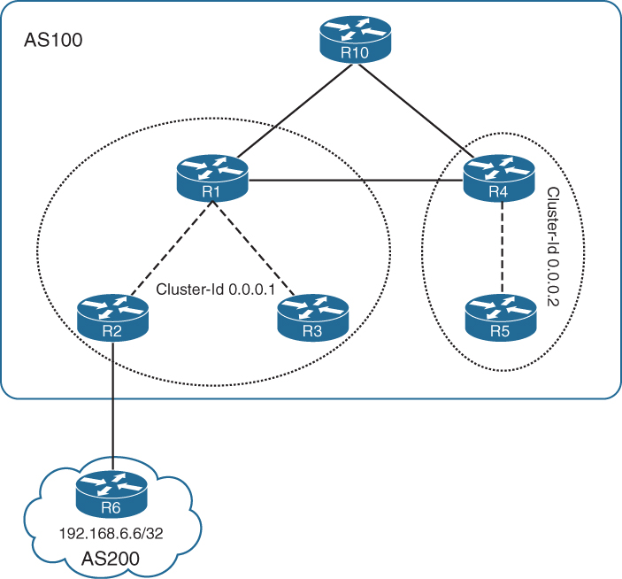
R6 advertises the loopback address 192.168.6.6/32 toward R2. R2 then advertises the prefix to R1, which is the RR, but the BGP table of R3 does not show the prefix 192.168.6.6/32 because it is blocked due to the cluster list. The prefix advertised by RR router R1 has the cluster ID of 0.0.0.1, which is same as that of R3. R3 drops the prefix from getting installed in the BGP table. But 192.168.6.6/32 is successfully advertised to R4 and is seen in the BGP table as R6 having a different cluster ID i.e. 0.0.0.2. When R4 advertises the prefix to R5, it adds 0.0.0.2 in its prefix-list and R5 drops the update as it belongs to the same cluster 0.0.0.2.
Example 7-25 illustrates the loop prevention mechanism in the BGP cluster by displaying the BGP table of all the routers in AS100.
Example 7-25 BGP Cluster Loop Prevention Mechanism
R2# show bgp ipv4 unicast
Network Next Hop Metric LocPrf Weight Path
r>i 192.168.1.1/32 192.168.1.1 0 100 0 i
*> 192.168.2.2/32 0.0.0.0 0 32768 i
*> 192.168.6.6/32 10.1.26.6 0 200 i
R1# show bgp ipv4 unicast
Network Next Hop Metric LocPrf Weight Path
*> 192.168.1.1/32 0.0.0.0 0 32768 i
r>i 192.168.2.2/32 192.168.2.2 0 100 0 i
r>i 192.168.3.3/32 192.168.3.3 0 100 0 i
r>i 192.168.4.4/32 192.168.4.4 0 100 0 i
r>i 192.168.5.5/32 192.168.5.5 0 100 0 i
*>i 192.168.6.6/32 192.168.2.2 0 100 0 200 i
R3# show bgp ipv4 unicast
Network Next Hop Metric LocPrf Weight Path
r>i 192.168.1.1/32 192.168.1.1 0 100 0 i
*> 192.168.3.3/32 0.0.0.0 0 32768 i
R4# show bgp ipv4 unicast
Network Next Hop Metric LocPrf Weight Path
r>i 192.168.1.1/32 192.168.1.1 0 100 0 i
r>i 192.168.2.2/32 192.168.2.2 0 100 0 i
r>i 192.168.3.3/32 192.168.3.3 0 100 0 i
*> 192.168.4.4/32 0.0.0.0 0 32768 i
r>i 192.168.5.5/32 192.168.5.5 0 100 0 i
*>i 192.168.6.6/32 192.168.2.2 0 100 0 200 i
R5# show bgp ipv4 unicast
Network Next Hop Metric LocPrf Weight Path
r>i 192.168.4.4/32 192.168.4.4 0 100 0 i
*> 192.168.5.5/32 0.0.0.0 0 32768 i
If both RRs are in different clusters, the second RR holds the paths from the first RR and consumes more memory and CPU. The two methods of using the same cluster-id or different cluster-id have their own disadvantages, which should be understood when choosing an RR design. The disadvantages are as follows:
![]() Different cluster-id
Different cluster-id
![]() Additional memory and CPU overhead on RR
Additional memory and CPU overhead on RR
![]() Same cluster-id
Same cluster-id
![]() Less redundant paths
Less redundant paths
If the bgp cluster-id command is removed from router R5 as shown in Example 7-26, then both the prefix 192.168.6.6/32 can be viewed in R5 BGP table. The prefix is also seen with both the cluster IDs in the CLUSTER-LIST.
Example 7-26 Removing the bgp cluster-id Command
R5(config)# router bgp 100
R5(config-router)# no bgp cluster-id
R5# show bgp ipv4 unicast 192.168.6.6
BGP routing table entry for 192.168.6.6/32, version 12
Paths: (1 available, best #1, table default)
Not advertised to any peer
Refresh Epoch 1
200
192.168.2.2 (metric 4) from 192.168.4.4 (192.168.4.4)
Origin IGP, metric 0, localpref 100, valid, internal, best
Originator: 192.168.2.2, Cluster list: 0.0.0.2, 0.0.0.1
rx pathid: 0, tx pathid: 0x0
Note
It is not a recommended design to have the bgp cluster-id command configured on the RR client routers and should only be configured on the RR routers. The configuration here on the RR client is just used for demonstration purposes.
If the RR clients are fully meshed within the cluster, the no bgp client-to-client reflection command can be enabled on the RR.
Note
As a best practice, full mesh between the RRs and the nonclients should be kept small.
Starting with the 15.2(1)S IOS release and 3.8 XR release, Cisco added the support for the Multi-Cluster ID (MCID) feature. The MCID functionality allows for a router-reflector to configure a cluster-id per neighbor. When a cluster-id is configured on a per-neighbor basis, functionality is changed in two ways:
![]() CLUSTER_LIST–based loop detection mechanism
CLUSTER_LIST–based loop detection mechanism
![]() Disabling client to client route reflection based on cluster-id
Disabling client to client route reflection based on cluster-id
When propagating a route with the MCID feature, the RR appends the cluster-id of the router from which the route was received to the CLUSTER_LIST. If the neighbor does not have an associated cluster-id, it uses the global cluster-id instead. For loop prevention with MCID, the receiving router discards the route if any of the global or per-neighbor cluster-id is found in the CLUSTER_LIST.
Example 7-27 illustrates how to configure per-neighbor cluster-id.
Example 7-27 MCID Configuration
IOS
R5(config)# router bgp 100
R5(config-router)# cluster-id 0.0.0.1
R5(config-router)# neighbor 192.168.4.4 cluster-id 0.0.0.1
IOS XR
RP/0/0/CPU0:R4(config)# router bgp 100
RP/0/0/CPU0:R4(config-bgp)# bgp cluster-id 0.0.0.2
RP/0/0/CPU0:R4(config-bgp)# neighbor 192.168.1.1
RP/0/0/CPU0:R4(config-bgp-nbr)# remote-as 100
RP/0/0/CPU0:R4(config-bgp-nbr)# cluster-id 0.0.0.1
RP/0/0/CPU0:R4(config-bgp-nbr)# update-source loopback0
RP/0/0/CPU0:R4(config-bgp-nbr)# address-family ipv4 unicast
In Example 7-25, R4 learned the prefix from R1 because R4 was having a different cluster-id. But with the new MCID configuration, R4 no longer learns the prefixes from R1. This is because router R4 is now configured as the cluster-id 0.0.0.1 for neighbor 192.168.1.1. Example 7-28 displays the BGP table after the MCID implementation. In the output, notice that R4 does not contain the loopback routes from R2, R3, and R6.
Example 7-28 MCID Configuration
RP/0/0/CPU0:R4# show bgp ipv4 unicast
! Output omitted for brevity
Status codes: s suppressed, d damped, h history, * valid, > best
i - internal, r RIB-failure, S stale, N Nexthop-discard
Origin codes: i - IGP, e - EGP, ? - incomplete
Network Next Hop Metric LocPrf Weight Path
*>i192.168.1.1/32 192.168.1.1 0 100 0 i
*> 192.168.4.4/32 0.0.0.0 0 32768 i
*>i192.168.5.5/32 192.168.5.5 0 100 0 i
Processed 3 prefixes, 3 paths
With the MCID feature, an RR client can peer not only with the RR in the same cluster but also with an RR in another cluster. Example 7-29 illustrates RR client R3 in cluster 0.0.0.1 peering with RR router R4 in cluster 0.0.0.2. The session is part of cluster 0.0.0.2. Notice that after the BGP peering, R4 has the prefix 192.168.3.3/32 in its BGP table. This prefix is not advertised to R5. Any prefix from R5 is advertised to R3.
Example 7-29 Intercluster Peering
IOS
R3(config)# router bgp 100
R3(config-router)# neighbor 192.168.4.4 remote-as 100
R3(config-router)# neighbor 192.168.4.4 update-source loopback0
R3(config-router)# neighbor 192.168.4.4 cluster-id 0.0.0.2
R3(config-router)# address-family ipv4 unicast
R3(config-router-af)# neighbor 192.168.4.4 activate
R3(config-router-af)# neighbor 192.168.4.4 next-hop-self
R3# show bgp ipv4 unicast
! Output omitted for brevity
Network Next Hop Metric LocPrf Weight Path
r>i 192.168.1.1/32 192.168.1.1 0 100 0 i
*> 192.168.3.3/32 0.0.0.0 0 32768 i
r>i 192.168.4.4/32 192.168.4.4 0 100 0 i
IOS XR
RP/0/0/CPU0:R4(config)# router bgp 100
RP/0/0/CPU0:R4(config-bgp)# neighbor 192.168.3.3
RP/0/0/CPU0:R4(config-bgp-nbr)# remote-as 100
RP/0/0/CPU0:R4(config-bgp-nbr)# update-source loopback0
RP/0/0/CPU0:R4(config-bgp-nbr)# address-family ipv4 unicast
RP/0/0/CPU0:R4(config-bgp-nbr-af)# route-reflector-client
RP/0/0/CPU0:R4(config-bgp-nbr-af)# commit
RP/0/0/CPU0:R4# show bgp ipv4 unicast
! Output omitted for brevity
Network Next Hop Metric LocPrf Weight Path
*>i192.168.1.1/32 192.168.1.1 0 100 0 i
*>i192.168.3.3/32 192.168.3.3 0 100 0 i
*> 192.168.4.4/32 0.0.0.0 0 32768 i
*>i192.168.5.5/32 192.168.5.5 0 100 0 i
Processed 4 prefixes, 4 paths
With the introduction of the MCID feature, there have also been some enhancements with client-to-client reflection functionality. By default, in classical mode, the command no bgp client-to-client reflection helps disable the reflection of routes by the RR when the clients are fully meshed within the BGP cluster. But this command does not help when the clients have peering in different clusters; that is, intercluster peering.
The command to disable client-to-client route reflection for a particular cluster-id is no bgp client-to-client reflection intra-cluster cluster-id [any | cluster-id1 cluster-id2 ...].
The any keyword is used to specify that client-to-client reflection is disabled for any cluster. The old command for disabling all client-to-client reflection is still used: no bgp client-to-client reflection [all]. The all keyword is optional and disables both inter-cluster and intra-cluster client-to-client reflection.
In summary, three levels of commands are used to disable client-to-client reflection:
![]() Level 1: no bgp client-to-client reflection [all]. Disables intra-cluster and inter-cluster client-to-client reflection.
Level 1: no bgp client-to-client reflection [all]. Disables intra-cluster and inter-cluster client-to-client reflection.
![]() Level 2: no bgp client-to-client reflection intra-cluster cluster-id any. Disables intra-cluster client-to-client reflection for any cluster-id.
Level 2: no bgp client-to-client reflection intra-cluster cluster-id any. Disables intra-cluster client-to-client reflection for any cluster-id.
![]() Level 3: no bgp client-to-client reflection intra-cluster cluster-id [cluster-id1 cluster-id2 ...]. Disables intra-cluster client-to-client reflection for the specified cluster-ids.
Level 3: no bgp client-to-client reflection intra-cluster cluster-id [cluster-id1 cluster-id2 ...]. Disables intra-cluster client-to-client reflection for the specified cluster-ids.
Cisco IOS also provides the command show bgp afi safi cluster-ids [internal] to view the configured and used BGP client-to-client reflection method. The keyword internal is hidden and displays additional information.
Example 7-30 displays the output of the show bgp ipv4 unicast cluster-ids internal command, which shows the global cluster-id as 0.0.0.1 and configured per-neighbor cluster-id as 0.0.0.2. Notice that in the first part of the output, the C2C-rfl-CFG and C2C-rfl-USE fields show the value as ENABLED, which means that client-to-client reflection is happening. Later when the client-to-client reflection is disabled, the output shows the state of these fields as DISABLED. This is a quick method to verify the behavior when using cluster-ids.
Example 7-30 Intercluster Peering
R1# show bgp ipv4 unicast cluster-ids internal
Global cluster-id: 0.0.0.1 (configured: 0.0.0.1)
BGP client-to-client reflection: Configured Used
all (inter-cluster and intra-cluster): ENABLED
intra-cluster: ENABLED ENABLED
Cluster-id head : 0x102AF5A8
Cluster-id chunk: 0xEFF5AE0
List of cluster-ids:
Cluster-id #-neighbors C2C-rfl-CFG C2C-rfl-USE Refcount Address
0.0.0.2 1 ENABLED ENABLED 2 0x11BCE08C
R1(config)# router bgp 100
R1(config-router)# no bgp client-to-client reflection all
R1# show bgp ipv4 unicast cluster-ids internal
Global cluster-id: 0.0.0.1 (configured: 0.0.0.1)
BGP client-to-client reflection: Configured Used
all (inter-cluster and intra-cluster): ENABLED
intra-cluster: ENABLED ENABLED
Cluster-id head : 0x102AF5A8
Cluster-id chunk: 0xEFF5AE0
List of cluster-ids:
Cluster-id #-neighbors C2C-rfl-CFG C2C-rfl-USE Refcount Address
0.0.0.1 0 DISABLED DISABLED 2 0x11BCE034
0.0.0.2 1 DISABLED DISABLED 2 0x11BCE08C
Hierarchical Route Reflectors
It is so far clear that RRs help in scaling the full-mesh IBGP sessions. But in large-scale deployments, a single layer of RRs might not be enough to scale the whole network. With additional RR clients attached to an RR, more BGP updates and BGP keepalives are required to be processed by the RR router. This can consume a lot of CPU and memory resources.
Network designers can build route reflector clusters in hierarchies. With hierarchies, a router serving as an RR in one cluster can act as a client in another cluster. When a first level of BGP cluster is built, the remaining full mesh IBGP sessions are usually smaller. But if the remaining nonclient sessions are large, then additional levels of RRs can be configured. Figure 7-17 illustrates hierarchical RR topology design. In this topology, the first level of an RR cluster is built by creating cluster 10 and 20. This step reduced the original full mesh of 14 routers to a full mesh of eight routers. The second level of RR cluster is then built by creating cluster 100. This step further reduced the full mesh of eight routers to a full mesh consisting of only two routers. Only the two RRs in the cluster 100 are required to form peering with the RR routers in other clusters and also a full mesh peering with the nonclient routers.

When a client in the lowest level receives an EBGP update, it forwards it on to all configured RRs in the first level. The RR recognizes the update and forwards the update to the other clients within the same cluster and the other IBGP sessions (nonclients). The nonclient sessions are the second-level RRs. The second-level RRs receive the update and then replicate it to their clients and to the other peer in a full mesh.
Though hierarchical RR provides scalability in the number of full-mesh IBGP sessions, it does not provide scalability in terms of routes that it can handle. Hierarchical RRs add complexity with additional RRs and may possibly lead to performance degradations.
Note
It is recommended to have hierarchical RRs implemented using clusters, and a cluster-id should be configured on the RRs.
Partitioned Route Reflectors
Sometimes dedicated RRs in large-scale environments (especially service provider networks) do not scale to the demands of a large customer, who might be acting as a provider for their customers that are carrying a large number of VPNv4 prefixes. In such scenarios, partitioning of the RR roles between multiple RR routers help scale the requirements. RR partitioning is achieved by using two methods:
![]() Using BGP RR groups: BGP RR groups is an inbound route target (RT) filtering method that is available only for VPNv4 and VPNv6 address-families. Configure inbound RT filtering using the command bgp rr-groups extcommunity-list-name. The configured extcommunity-list specifies the RT values to be permitted by the RR. The bgp rr-groups command applies to all neighbors configured under the address-family.
Using BGP RR groups: BGP RR groups is an inbound route target (RT) filtering method that is available only for VPNv4 and VPNv6 address-families. Configure inbound RT filtering using the command bgp rr-groups extcommunity-list-name. The configured extcommunity-list specifies the RT values to be permitted by the RR. The bgp rr-groups command applies to all neighbors configured under the address-family.
![]() Using Standard BGP communities: Standard BGP communities can be used as inbound filters on RR and outbound filters on the PE router to filter the VPNv4 or VPNv6 prefixes. A community value is set for the CE prefixes and sent across toward the RR router. The RR routers filter those prefixes based on the community value assigned by the PE. This method allows for per-neighbor–based filtering but may increase CPU resource consumption on the RR routers and also adds an additional burden of maintenance for the configured filters.
Using Standard BGP communities: Standard BGP communities can be used as inbound filters on RR and outbound filters on the PE router to filter the VPNv4 or VPNv6 prefixes. A community value is set for the CE prefixes and sent across toward the RR router. The RR routers filter those prefixes based on the community value assigned by the PE. This method allows for per-neighbor–based filtering but may increase CPU resource consumption on the RR routers and also adds an additional burden of maintenance for the configured filters.
Note
You can still use redundant route reflectors even when partitioning.
For further understanding, examine the topology shown in Figure 7-18. Four routers are part of the service provider network. PE1 and PE2 are the edge routers, RR1 and RR2 are the provider as well as RR routers. Each PE provides VPN services to two customers, VPN_A and VPN_B.

RR1 and RR2 are both participating in the control plane and data plane forwarding. To demonstrate route partitioning, RR1 accepts routes only from VPN_A, and RR2 accepts routes only from VPN_B. Example 7-31 demonstrates the configuration of PE as well the RR routers; RR1 is filtering the RT value 100:1, which is for customer VPN_A, and RR2 is filtering RT value 100:2, which is for customer VPN_B.
Example 7-31 Partitioned RR with Inbound RT Filters
PE Config
ip vrf VPN_A
rd 100:1
route-target export 100:1
route-target import 100:1
!
ip vrf VPN_B
rd 100:2
route-target export 100:2
route-target import 100:2
!
router bgp 100
neighbor 192.168.10.10 remote-as 100
neighbor 192.168.10.10 update-source Loopback0
neighbor 192.168.20.20 remote-as 100
neighbor 192.168.20.20 update-source Loopback0
!
address-family vpnv4
neighbor 192.168.10.10 activate
neighbor 192.168.10.10 send-community both
neighbor 192.168.10.10 next-hop-self
neighbor 192.168.20.20 activate
neighbor 192.168.20.20 send-community both
neighbor 192.168.20.20 next-hop-self
exit-address-family
!
address-family ipv4 vrf VPN_A
. . .
!
address-family ipv4 vrf VPN_B
. . .
RR1 Config
router bgp 100
no bgp default ipv4-unicast
neighbor 192.168.1.1 remote-as 100
neighbor 192.168.1.1 update-source Loopback0
neighbor 192.168.2.2 remote-as 100
neighbor 192.168.2.2 update-source Loopback0
neighbor 192.168.20.20 remote-as 100
neighbor 192.168.20.20 update-source Loopback0
!
address-family vpnv4
neighbor 192.168.1.1 activate
neighbor 192.168.1.1 send-community both
neighbor 192.168.1.1 route-reflector-client
neighbor 192.168.2.2 activate
neighbor 192.168.2.2 send-community both
neighbor 192.168.2.2 route-reflector-client
neighbor 192.168.20.20 activate
neighbor 192.168.20.20 send-community both
bgp rr-group VPNA
exit-address-family
!
ip extcommunity-list standard VPNA permit rt 100:1
RR2 Config
router bgp 100
neighbor 192.168.1.1 remote-as 100
neighbor 192.168.1.1 update-source Loopback0
neighbor 192.168.2.2 remote-as 100
neighbor 192.168.2.2 update-source Loopback0
neighbor 192.168.10.10 remote-as 100
neighbor 192.168.10.10 update-source Loopback0
!
address-family vpnv4
neighbor 192.168.1.1 activate
neighbor 192.168.1.1 send-community both
neighbor 192.168.1.1 route-reflector-client
neighbor 192.168.2.2 activate
neighbor 192.168.2.2 send-community both
neighbor 192.168.2.2 route-reflector-client
neighbor 192.168.10.10 activate
neighbor 192.168.10.10 send-community both
bgp rr-group VPNB
exit-address-family
!
ip extcommunity-list standard VPNB permit rt 100:2
If the RR partitioning is not performed, the PE2 learns the routes from PE1 for each customer VRF VPN_A and VPN_B via two paths: RR1 and RR2. One of them is chosen as the best path. But because RR partitioning is implemented, PE2 only sees one path for prefixes from VPN_A and VPN_B. Examine the output in Example 7-32. VPN_A prefixes are learned or reflected via RR1, whereas VPN_B prefixes are learned via RR2.
Example 7-32 Partitioned RR with Inbound RT Filters
PE2# show bgp vpnv4 unicast all 172.16.11.0
BGP routing table entry for 100:1:172.16.11.0/24, version 10
Paths: (1 available, best #1, table VPN_A)
Not advertised to any peer
Refresh Epoch 1
Local
192.168.1.1 (metric 3) (via default) from 192.168.10.10 (192.168.10.10)
Origin incomplete, metric 0, localpref 100, valid, internal, best
Extended Community: RT:100:1
Originator: 192.168.1.1, Cluster list: 192.168.10.10
mpls labels in/out nolabel/22
rx pathid: 0, tx pathid: 0x0
PE2# show bgp vpnv4 unicast all 172.16.21.0
BGP routing table entry for 100:2:172.16.21.0/24, version 14
Paths: (1 available, best #1, table VPN_B)
Not advertised to any peer
Refresh Epoch 1
Local
192.168.1.1 (metric 3) (via default) from 192.168.20.20 (192.168.20.20)
Origin incomplete, metric 0, localpref 100, valid, internal, best
Extended Community: RT:100:2
Originator: 192.168.1.1, Cluster list: 192.168.20.20
mpls labels in/out nolabel/23
rx pathid: 0, tx pathid: 0x0
Implementing partitioned RRs using inbound route target filters is very easy to implement because it uses the BGP rr-group feature. The other method to implement partitioned RRs is to use standard BGP communities. This method involves route-maps to set the community tags and match them on the RR to filter the updates. Example 7-33 shows the configuration of both the PE and RR routers for partitioning RR using standard BGP communities.
Example 7-33 Partitioned RR with Standard BGP Communities
PE1 Config
router bgp 100
address-family vpnv4
neighbor 192.168.10.10 activate
neighbor 192.168.10.10 send-community both
neighbor 192.168.10.10 route-map VPNA out
neighbor 192.168.20.20 activate
neighbor 192.168.20.20 send-community both
neighbor 192.168.20.20 route-map VPNB out
exit-address-family
!
ip bgp-community new-format
!
access-list 10 permit 172.16.11.0 0.0.0.255
access-list 20 permit 172.16.21.0 0.0.0.255
!
route-map VPNA permit 10
match ip address 10
set community 100:1
!
route-map VPNB permit 10
match ip address 20
set community 100:2
PE2 Config
! Rest of the Config is same as PE1
access-list 10 permit 172.16.23.0 0.0.0.255
access-list 20 permit 172.16.24.0 0.0.0.255
!
route-map VPNA permit 10
match ip address 10
set community 100:1
!
route-map VPNB permit 10
match ip address 20
set community 100:2
RR1 Config
router bgp 100
address-family vpnv4
neighbor 192.168.1.1 activate
neighbor 192.168.1.1 send-community both
neighbor 192.168.1.1 route-reflector-client
neighbor 192.168.1.1 route-map VPNA in
neighbor 192.168.2.2 activate
neighbor 192.168.2.2 send-community both
neighbor 192.168.2.2 route-reflector-client
neighbor 192.168.2.2 route-map VPNA in
neighbor 192.168.20.20 activate
neighbor 192.168.20.20 send-community both
neighbor 192.168.20.20 route-map VPNA in
exit-address-family
!
ip bgp-community new-format
ip community-list 1 permit 100:1
!
route-map allow-VPNA permit 10
match community 1
RR2 Config
router bgp 100
address-family vpnv4
neighbor 192.168.1.1 activate
neighbor 192.168.1.1 send-community both
neighbor 192.168.1.1 route-reflector-client
neighbor 192.168.1.1 route-map VPNB in
neighbor 192.168.2.2 activate
neighbor 192.168.2.2 send-community both
neighbor 192.168.2.2 route-reflector-client
neighbor 192.168.2.2 route-map VPNB in
neighbor 192.168.10.10 activate
neighbor 192.168.10.10 send-community both
neighbor 192.168.10.10 route-map VPNB in
exit-address-family
!
ip bgp-community new-format
ip community-list 1 permit 100:2
!
route-map allow-VPNB permit 10
match community 1
Example 7-33 achieves the same results as shown in Example 7-32. The only difference is the method used. The later method is more complex and resource consuming because it has more customers. Additional community attributes have to be set and the route-map becomes larger.
BGP Selective Route Download
There are two ways RRs are deployed in the network from the perspective of forwarding path:
![]() When RRs are present in the forwarding path
When RRs are present in the forwarding path
![]() When RRs are separated from the forwarding path
When RRs are separated from the forwarding path
When RRs are part of the forwarding path, the RR router not only has to perform RR activities but participate in the lookup and forwarding decisions of the packet. When RRs are separated from the forwarding path and are supposed to only perform RR activities, they are saved from the lookup and forwarding decision-making activities on the router, which saves a lot of CPU cycles. Such RRs are also called Out-of-Band Route Reflectors or Dedicated RRs, often also called off-path RRs or RR-on-a-stick.
The default behavior for any BGP router in the path, and even for RRs, requires the route to be downloaded to the RIB before the prefixes are replicated or advertised to the peers. In case of Out-of-Band RRs, there is no real need to have the routes downloaded into the RIB because such RRs are not in the forwarding path (data path).
To avoid the BGP routes from getting installed in the RIB, specifically on the RRs, use the BGP selective route download or selective RIB download feature. The BGP selective route download feature saves on both memory and CPU resources on the router. This feature is implemented using the filter keyword with the table-map command. Example 7-34 illustrates the implementation of the selective route download feature using the topology shown in Figure 7-19.

In Example 7-34, an empty route-map BLOCK-INTO-FIB is configured with the deny option. This denies all the routes from getting downloaded into the RIB and the FIB.
Example 7-34 BGP Selective Route Download Configuration
IOS
R1(config)# route-map BLOCK-INTO-FIB deny 10
R1(config)# router bgp 100
R1(config-router)# address-family ipv4 unicast
R1(config-router-af)# table-map BLOCK-INTO-FIB filter
R1(config-router-af)# end
IOS XR
RP/0/0/CPU0:R2(config)# route-policy BLOCK-INTO-FIB
RP/0/0/CPU0:R2(config-rpl)# drop
RP/0/0/CPU0:R2(config-rpl)# exit
RP/0/0/CPU0:R2(config)# router bgp 100
RP/0/0/CPU0:R2(config-bgp)# address-family ipv4 unicast
RP/0/0/CPU0:R2(config-bgp-af)# table-policy BLOCK-INTO-FIB
RP/0/0/CPU0:R2(config-bgp-af)# commit
NX-OS
R3(config)# route-map BLOCK-INTO-FIB deny 10
R3(config)# router bgp 100
R3(config-router)# address-family ipv4 unicast
R3(config-router-af)# table-map BLOCK-INTO-FIB filter
R3(config-router-af)# end
With the configuration shown in Example 7-34, the command show ip route bgp will not display any routes in the output, whereas BGP table will hold all the routes in the BGP table. If only certain prefixes are required to be downloaded into the RIB and the FIB, the route-map or the route-policy statements can be modified accordingly. Example 7-35 illustrates the modification of routing policy for partial download of the routes in the RIB. It shows the BGP table and the routing table after the route-map is modified to deny two prefixes and allow the rest of the prefixes, unless the permit statement is configured as part of the route-map, even if the selected prefixes are denied in the sequence 10 statement. All the prefixes are blocked from being downloaded into the RIB.
Example 7-35 BGP Selective Route Download Configuration
IOS
R1(config)# route-map BLOCK-INTO-FIB deny 10
R1(config-route-map)# match ip address prefix-list BLOCK-IP
R1(config-route-map)# exit
R1(config)# route-map BLOCK-INTO-FIB permit 20
R1(config-route-map)# exit
R1(config)# ip prefix-list BLOCK-IP seq 5 permit 192.168.102.0/24
R1(config)# ip prefix-list BLOCK-IP seq 10 permit 192.168.103.0/24
R1(config)# end
! Verifying BGP Table
R1# show bgp ipv4 unicast
! Output omitted for brevity
Network Next Hop Metric LocPrf Weight Path
*> 192.168.100.0 10.1.101.2 2219 0 200 134 115 149 {117} e
*> 192.168.101.0 10.1.101.2 2219 0 200 134 115 149 {117} e
*> 192.168.102.0 10.1.101.2 2219 0 200 134 115 149 {117} e
*> 192.168.103.0 10.1.101.2 2219 0 200 134 115 149 {117} e
*> 192.168.104.0 10.1.101.2 2219 0 200 134 115 149 {117} e
! Verifying Routing Table
R1# show ip route bgp
! Output omitted for brevity
B 192.168.100.0/24 [20/2219] via 10.1.101.2, 10:29:04
B 192.168.101.0/24 [20/2219] via 10.1.101.2, 10:29:04
B 192.168.104.0/24 [20/2219] via 10.1.101.2, 10:29:04
IOS XR
! RPL Configuration
route-policy BLOCK-INTO-FIB
if destination in (192.168.102.0/24) or destination in (192.168.103.0/24) then
drop
else
pass
endif
end-policy
! Verifying BGP Table
RP/0/0/CPU0:R2# show bgp ipv4 unicast
! Output omitted for brevity
Network Next Hop Metric LocPrf Weight Path
*> 192.168.100.0/24 10.1.102.2 2219 0 200 134 115 149 {117} e
*> 192.168.101.0/24 10.1.102.2 2219 0 200 134 115 149 {117} e
*> 192.168.102.0/24 10.1.102.2 2219 0 200 134 115 149 {117} e
*> 192.168.103.0/24 10.1.102.2 2219 0 200 134 115 149 {117} e
*> 192.168.104.0/24 10.1.102.2 2219 0 200 134 115 149 {117} e
! Verifying Routing Table
RP/0/0/CPU0:R2# show route bgp
B 192.168.100.0/24 [20/2219] via 10.1.102.2, 00:00:00
B 192.168.101.0/24 [20/2219] via 10.1.102.2, 00:00:00
B 192.168.104.0/24 [20/2219] via 10.1.102.2, 00:00:00
A similar configuration of Cisco IOS can be used to modify the route-map on Nexus devices.
Note
It is important that the RRs should not be configured with next-hop-self when using this feature because this may cause the traffic to be black holed. This is because the command next-hop-self will make the RR participate in the forwarding path, but because it does not have the prefix in the RIB, traffic may get black holed. The next-hop-self should be configured on the ASBRs or Internet edge routers.
Virtual Route Reflectors
BGP Route Reflection as defined in RFC 4456 has been the de facto choice for scaling IBGP deployments for both service providers and enterprises worldwide. Traditionally, RRs were deployed using either core routers or dedicated physical hardware solely for control-plane route-reflection purposes. Although this has proven to be a viable solution that meets the demands of BGP with all the CPU and memory required, it lacks flexibility, elasticity, and agility to meet the constantly changing demands of the services.
Dedicated RRs, often also called off-path RRs or RR-on-a-stick, require a powerful CPU for intensive path computation and sufficient memory to store all the learned routes (even if it is required to store multiple copies of the Internet routing table). The two main functions or features required on dedicated RR are the following:
![]() IGP
IGP
![]() BGP
BGP
Throughput is not really a key factor because RRs in such deployments are not in forwarding path, although bandwidth is a key requirement for communication of BGP path updates.
Over the years, memory and CPU has become less expensive, and the industry has expanded its acceptance toward virtualization technologies. Virtualization technologies are a faster and more reliable method of deploying new services and reducing capital expenditure (CapEx) and operating expenses (OpEx).
The networking industry has revolutionized toward Network Function Virtualization (NFV). Deploying virtualized network function (VNF) in the form of virtual route reflector (vRR) is proving to be the solution to the problems faced with physical hardware to perform the same task. It is cheaper to add CPU and memory to a server that can perform the same tasks as a physical router and at the same time run multiple virtual instances from the same physical server, which saves on power consumption significantly.
There are many benefits of using vRR, which include the following:
![]() Scalability (64bit OS)
Scalability (64bit OS)
![]() Performance (Multicore)
Performance (Multicore)
![]() Manageability
Manageability
![]() Same software version as deployed on edge (IOS XE / IOS XR)
Same software version as deployed on edge (IOS XE / IOS XR)
![]() vMotion (Hypervisor)
vMotion (Hypervisor)
Figure 7-20 illustrates a sample topology with four virtual route reflectors (vRR).

Cisco provides a vRR solution using two main products:
![]() Cloud Services Router (CSR) 1000v
Cloud Services Router (CSR) 1000v
![]() IOS XRv
IOS XRv
CSR 1000v can also be described as a virtualized IOS XE router. CSR 1000v is generalized to work on any x86-based processor with control plane and data plane mapped to virtual CPUs (vCPUs.) The CSR 1000v now comes in both 32-bit and 64-bit IOS XE OS. Because CSR 1000v leverages IOS XE code-base from ASR1000, RR features are part of the code-base. Figure 7-21 displays the architecture of the CSR1000v platform.

The various components for packet path within CSR 1000v include the following:
![]() Ethernet Driver (ingress)
Ethernet Driver (ingress)
![]() Receive (Rx) thread
Receive (Rx) thread
![]() PPE Thread (packet processing)
PPE Thread (packet processing)
![]() HQF Thread (egress queueing)
HQF Thread (egress queueing)
![]() Ethernet Driver (egress)
Ethernet Driver (egress)
Explanation of all the components of packet processing within CSR 1000v is outside the scope of this book. Please refer to the “Reference” section for more information on CSR 1000v.
IOS XRv is a virtual router that uses the same carrier-class Cisco IOS XR operating system powering the ASR9000 and Carrier Routing System (CRS) series high-end routers. It provides the same key benefits as IOS XR while providing elasticity, agility, and flexibility that VNF brings.
IOS XRv is a virtual machine-based platform-independent representation of classic 32-bit x86 IOS XR with a QNX kernel. It is a single VM router, with the hardware model presented being a single VM containing the route processor (RP) functionality and line card interfaces with both the RP control-plane functionality, and the network interfaces and line card functionality running on the same virtual card.
Figure 7-22 displays the IOS XRv platform. There are four major components in the architecture:
![]() Full standard XR Platform Independent (PI) binaries
Full standard XR Platform Independent (PI) binaries
![]() Platform Layer
Platform Layer
![]() Software Packet Path (SPP) Data Plane
Software Packet Path (SPP) Data Plane
![]() QNX (Kernel)
QNX (Kernel)

Table 7-6 describes all the IOS XRv components.

Both CSR 1000v and IOS XRv are available as individual images for download as well as part of Cisco Modelling Labs (CML), previously known as VIRL.
Cisco recently launched the IOS XRv 9000 cloud-based router that is deployed as a VM instance on an x86 server running 64-bit IOS XR software. The IOS XRv 9000 provides traditional provider edge services along with vRR capabilities. The major difference between IOS XRv and IOS XRv 9000 is that the IOS XR 9000v router combines RP, line card, and virtualized forwarding capabilities into a single, centralized forwarding instance; that is, IOS XRv 9000 supports a high speed virtual x86 data plane.
BGP Diverse Path
BGP route reflectors have been the de facto feature in any network deployment for IBGP sessions and provides various capabilities as discussed in this chapter. But with benefits, there are certain limitations and problems that come along with this feature. The BGP-4 protocol specification requires the router to advertise only the best path for a destination. The BGP multipath feature helps provide load-balancing features over multiple paths along with resiliency and faster recovery from failures. The RR router only selects and advertises a single best path for each prefix, even if there are multiple paths available for the prefix on the RR. This breaks the BGP multipath functionality when RR is present in the path.
To better understand the issues in detail, examine the topology in Figure 7-23. R4 and R41 are acting as the RR, whereas R2, R3, and R5 are the RR clients. R2 and R3 are having an EBGP session with R1. Now examine the topology with the single RR router R4. There are two paths from R4 to reach R1—via R4 - R2 - R1 and R4 - R3 - R1. But when the route is reflected to R5, it receives only one best path that is chosen by the RR. RR router R4 receives two paths but because of the best-path selection algorithm, RR only advertises the best path to R5. This makes R5 think it has only one path and cannot utilize the BGP multipath.

Example 7-36 illustrates the RR problem explained in Figure 7-23. The EBGP peer R1 advertises prefix 192.168.1.1/32 toward R2 and R3. Routers R2 and R3 then advertises that prefix toward the RR router R4. R4 sees the prefix via two paths but selects the path via R2 as the best. R4 then reflects the best path toward R5. The router R5 can only see the best path with the next-hop as R2.
Example 7-36 BGP RR Advertising Only Best Path
R4# show bgp ipv4 unicast 192.168.1.1
BGP routing table entry for 192.168.1.1/32, version 3
Paths: (2 available, best #2, table default)
Advertised to update-groups:
1
Refresh Epoch 1
200, (Received from a RR-client)
192.168.3.3 (metric 2) from 192.168.3.3 (192.168.3.3)
Origin IGP, metric 0, localpref 100, valid, internal
rx pathid: 0, tx pathid: 0
Refresh Epoch 1
200, (Received from a RR-client)
192.168.2.2 (metric 2) from 192.168.2.2 (192.168.2.2)
Origin IGP, metric 0, localpref 100, valid, internal, best
rx pathid: 0, tx pathid: 0x0
R5# show bgp ipv4 unicast
! Output omitted for brevity
Network Next Hop Metric LocPrf Weight Path
*>i 192.168.1.1/32 192.168.2.2 0 100 0 200 i
Even if a second RR was added in the topology beside R4—for instance, R41—it would also advertise the best path; that is, via R2. Example 7-37 displays the output on R5 for prefix 192.168.1.1 after adding another RR. Notice that both the prefixes are being learned from the next-hop 192.168.2.2, which is the loopback IP of R2.
Example 7-37 BGP RR Advertising Only Best Path
R5# show bgp ipv4 unicast 192.168.1.1
BGP routing table entry for 192.168.1.1/32, version 3
Paths: (2 available, best #2, table default)
Not advertised to any peer
Refresh Epoch 1
200
192.168.2.2 (metric 3) from 192.168.41.41 (192.168.41.41)
Origin IGP, metric 0, localpref 100, valid, internal
Originator: 192.168.2.2, Cluster list: 192.168.41.41
rx pathid: 0, tx pathid: 0
Refresh Epoch 2
200
192.168.2.2 (metric 3) from 192.168.4.4 (192.168.4.4)
Origin IGP, metric 0, localpref 100, valid, internal, best
Originator: 192.168.2.2, Cluster list: 192.168.4.4
rx pathid: 0, tx pathid: 0x0
When the exit point fails, traffic loss occurs until the control-plane converges. In such a scenario, the BGP Prefix Independent Convergence (PIC) feature doesn’t get triggered as well. Not knowing about other exit points apart from the one advertised also means that the ingress routers cannot do load balancing. To overcome this problem, the BGP diverse path distribution feature can be used. The BGP diverse path was introduced in the Cisco IOS 15.4(2)M and IOS XE 3.1.0S release. There are four methods to use the BGP diverse path distribution mechanism:
![]() Using unique RD on each PE
Using unique RD on each PE
![]() Using BGP best external feature
Using BGP best external feature
![]() Shadow route reflectors
Shadow route reflectors
![]() Shadow sessions
Shadow sessions
The first two options are discussed in Chapter 10, “MPLS Layer 3 VPN (L3VPN),” and Chapter 14, “BGP High Availability,” because they are more relevant to MPLS VPN deployments. Chapter 14 also covers the BGP PIC feature. This chapter focuses on using shadow RRs and shadow sessions.
Shadow Route Reflectors
A shadow RR is another RR router that is added within the AS to provide diverse path functionality. The role of the shadow RR, a.k.a. Diverse-Path route reflector, is to advertise a diverse path to its clients. In other words, a shadow RR advertises the second-best path to its RR clients. It is recommended to have the same physical and control-plane connectivity for the shadow RR as that of the primary RR.
Note
Only one shadow RR per existing RR can be configured in the AS. Also, this feature is meant to provide path diversity within a cluster.
There is a caveat to consider before implementing shadow RR. In certain designs, it is required to disable the IGP metric check for the shadow RR to function properly. There are two possibilities of how primary and shadow RR are located in the topology:
![]() Both RRs are co-located.
Both RRs are co-located.
![]() Both RRs are not co-located.
Both RRs are not co-located.
To understand both the design caveat, examine the two topologies shown in Figure 7-24. In topology A, both the RRs are co-located; that is, both RRs are either in a common subnet/VLAN connected via a switch or are deployed equidistant from both Internet Edge or PE routers. Because they are on the same VLAN with the same IGP metric toward the prefix, they do not require disabling the IGP metric check.

In topology B, both RRs are not co-located; that is, with all equal cost links, both RR1 and RR2 do not have the same IGP metric/cost to reach one of the PE routers. There is an extra hop in the middle, router P1, which adds to the IGP metric. This causes RR1 to have the link connected to PE1 as the best path to reach the prefix, whereas RR2 learns the best path to reach the prefix via the link connected to PE2 and not via router PE1. On router RR2, the path learned via PE1 becomes the second-best path, thus causing both the RRs to advertise the same path as the primary as well as the diverse path. To avoid this situation, disable the IGP metric check on both the primary and the shadow RR. To disable the IGP metric check, use the command bgp bestpath igp-metric ignore. This command causes BGP to ignore the IGP metric during the BGP best-path calculation.
Table 7-7 shows the commands required to configure shadow RR.

Examine the same topology as shown in Figure 7-23. RR R41 is the shadow RR, and R4 is the primary RR. R2 advertises the prefix 192.168.1.1/32 to both R4 and R41 with the next-hop value set to R2. Likewise, R3 advertises the same prefix with the next-hop value set to R3. R4 then sends an update to R5 that R2 is the next-hop router in order to reach 192.168.1.1/32. R41, which is the shadow RR advertising the second-best path, and announces the update that the next-hop to reach 192.168.1.1/32 prefix is via R3. This is how R5 has two diverse paths received from both the RRs.
Example 7-38 displays the additional configuration on router R41 and the output on router R5 after making R41 a shadow RR. The prefix 192.168.1.1/32 is being learned via two next-hops: R2 and R3.
Example 7-38 BGP Shadow RR Configuration and Output
R41(config)# router bgp 100
R41(config-router)# address-family ipv4 unicast
R41(config-router-af)# neighbor 192.168.5.5 advertise diverse-path backup
R41(config-router-af)# end
R5# show bgp ipv4 unicast 192.168.1.1
BGP routing table entry for 192.168.1.1/32, version 2
Paths: (2 available, best #2, table default)
Multipath: eBGP
Not advertised to any peer
Refresh Epoch 4
200
192.168.3.3 (metric 3) from 192.168.41.41 (192.168.41.41)
Origin IGP, metric 0, localpref 100, valid, internal
Originator: 192.168.3.3, Cluster list: 192.168.41.41
rx pathid: 0, tx pathid: 0
Refresh Epoch 3
200
192.168.2.2 (metric 3) from 192.168.4.4 (192.168.4.4)
Origin IGP, metric 0, localpref 100, valid, internal, best
Originator: 192.168.2.2, Cluster list: 192.168.4.4
rx pathid: 0, tx pathid: 0x0
Example 7-39 displays the output of show bgp ipv4 unicast neighbor ip-address advertised-routes command on R41, which shows that the route being advertised is a backup path.
Example 7-39 BGP Shadow RR Configuration and Output
R41# show bgp ipv4 unicast neighbors 192.168.5.5 advertised-routes
BGP table version is 5, local router ID is 192.168.41.41
Status codes: s suppressed, d damped, h history, * valid, > best, i - internal,
r RIB-failure, S Stale, m multipath, b backup-path, f RT-Filter,
x best-external, a additional-path, c RIB-compressed,
Origin codes: i - IGP, e - EGP, ? - incomplete
RPKI validation codes: V valid, I invalid, N Not found
Network Next Hop Metric LocPrf Weight Path
*bia192.168.1.1/32 192.168.3.3 0 100 0 200 i
Total number of prefixes 1
Now if the direct link from R2 to R41 and R3 to R4 is removed, and another router R6 is added in the middle for providing this cross connectivity as shown in Figure 7-25, then the IGP metric is different between R2 to R41 and R2 to R4. Similarly, the IGP metric is different from R3 to R4 and R3 to R41.

This makes R4 choose R2 as the best path and R41 choose R3 as the best path to reach R1. This causes the shadow RR router R41 to advertise the second-best path, which is via R2 as well. It breaks the purpose of having shadow RR in the topology. Example 7-40 illustrates this behavior with the help of outputs on R4, R41, and R5. This is the same scenario as explained when both the RRs are not co-located.
Example 7-40 Non Co-located RR Behavior
R4# show bgp ipv4 unicast 192.168.1.1
BGP routing table entry for 192.168.1.1/32, version 13
Paths: (2 available, best #1, table default)
Advertised to update-groups:
1
Refresh Epoch 1
200, (Received from a RR-client)
192.168.2.2 (metric 2) from 192.168.2.2 (192.168.2.2)
Origin IGP, metric 0, localpref 100, valid, internal, best
rx pathid: 0, tx pathid: 0x0
Refresh Epoch 1
200, (Received from a RR-client)
192.168.3.3 (metric 3) from 192.168.3.3 (192.168.3.3)
Origin IGP, metric 0, localpref 100, valid, internal
rx pathid: 0, tx pathid: 0
R41# show bgp ipv4 unicast 192.168.1.1
BGP routing table entry for 192.168.1.1/32, version 12
Paths: (2 available, best #1, table default)
Advertised to update-groups:
2
Refresh Epoch 2
200, (Received from a RR-client)
192.168.3.3 (metric 2) from 192.168.3.3 (192.168.3.3)
Origin IGP, metric 0, localpref 100, valid, internal, best
rx pathid: 0, tx pathid: 0x0
Refresh Epoch 2
200, (Received from a RR-client)
192.168.2.2 (metric 3) from 192.168.2.2 (192.168.2.2)
Origin IGP, metric 0, localpref 100, valid, internal, backup/repair
rx pathid: 0, tx pathid: 0
R5# show bgp ipv4 unicast 192.168.1.1
BGP routing table entry for 192.168.1.1/32, version 2
Paths: (2 available, best #2, table default)
Multipath: eBGP
Not advertised to any peer
Refresh Epoch 5
200, (received & used)
192.168.2.2 (metric 3) from 192.168.41.41 (192.168.41.41)
Origin IGP, metric 0, localpref 100, valid, internal
Originator: 192.168.2.2, Cluster list: 192.168.41.41
rx pathid: 0, tx pathid: 0
Refresh Epoch 4
200, (received & used)
192.168.2.2 (metric 3) from 192.168.4.4 (192.168.4.4)
Origin IGP, metric 0, localpref 100, valid, internal, best
Originator: 192.168.2.2, Cluster list: 192.168.4.4
rx pathid: 0, tx pathid: 0x0
This is where disabling the IGP metric check comes into play. By disabling the IGP metric check, both the primary and shadow RR do not advertise the same best path.
Example 7-41 demonstrates the behavior after the IGP metric check is disabled on both the RR routers.
Example 7-41 Non Co-located RR Behavior
R41# show bgp ipv4 unicast 192.168.1.1
BGP routing table entry for 192.168.1.1/32, version 8
BGP Bestpath: igpmetric-ignore
Paths: (2 available, best #1, table default)
Advertised to update-groups:
4
Refresh Epoch 4
200, (Received from a RR-client), (received & used)
192.168.2.2 (metric 3) from 192.168.2.2 (192.168.2.2)
Origin IGP, metric 0, localpref 100, valid, internal, best
rx pathid: 0, tx pathid: 0x0
Refresh Epoch 4
200, (Received from a RR-client), (received & used)
192.168.3.3 (metric 2) from 192.168.3.3 (192.168.3.3)
Origin IGP, metric 0, localpref 100, valid, internal, backup/repair
rx pathid: 0, tx pathid: 0
R5# show bgp ipv4 unicast 192.168.1.1
BGP routing table entry for 192.168.1.1/32, version 9
Paths: (2 available, best #2, table default)
Multipath: eBGP
Not advertised to any peer
Refresh Epoch 1
200, (received & used)
192.168.3.3 (metric 3) from 192.168.41.41 (192.168.41.41)
Origin IGP, metric 0, localpref 100, valid, internal
Originator: 192.168.3.3, Cluster list: 192.168.41.41
rx pathid: 0, tx pathid: 0
Refresh Epoch 1
200, (received & used)
192.168.2.2 (metric 3) from 192.168.4.4 (192.168.4.4)
Origin IGP, metric 0, localpref 100, valid, internal, best
Originator: 192.168.2.2, Cluster list: 192.168.4.4
rx pathid: 0, tx pathid: 0x0
Shadow Sessions
Shadow RR is an effective solution for advertising diverse paths or backup paths, but it requires an additional physical router to be installed in the cluster. This is not a very cost-effective solution and not every organization can afford to purchase an extra router or bear the cost of extra links. To overcome cost challenges, a shadow sessions feature can be used.
With shadow sessions, the primary RR is used to advertise both the primary as well as the backup path. This requires an extra BGP peering between the peer from the RR, where the backup path needs to be advertised. Because it is not possible to have two BGP sessions in same address-family on the same peering IPs, an extra loopback interface can be created to form the peering. After the peering is formed on the new loopback address, the neighbor ip-address advertise diverse-path backup command can then be used to advertise the backup path.
Examine the topology shown in Figure 7-23 with a single RR router R4 and ignoring another RR router R41. Example 7-42 illustrates the configuration of a shadow session on router R4 and R5. In this configuration, an additional loopback is created apart from loopback0 interface, and an additional peering is formed between R4 and R5, where R4 is the RR and R5 is the RR client. Notice that the command bgp additional-paths select backup is now configured on the primary router itself. Because this router is acting as both the primary and the backup router, this command is required.
Example 7-42 Shadow Session Configuration
R4
R4(config)# router bgp 100
R4(config-router)# neighbor 192.168.55.55 remote-as 100
R4(config-router)# neighbor 192.168.55.55 update-source loopback1
R4(config-router)# address-family ipv4 unicast
R4(config-router-af)# neighbor 192.168.55.55 activate
R4(config-router-af)# neighbor 192.168.55.55 route-reflector-client
R4(config-router-af)# neighbor 192.168.55.55 advertise diverse-path backup
R4(config-router-af)# bgp additional-paths select backup
R5
R5(config)# router bgp 100
R5(config-router)# neighbor 192.168.44.44 remote-as 100
R5(config-router)# neighbor 192.168.44.44 update-source loopback1
R5(config-router)# address-family ipv4 unicast
R5(config-router-af)# neighbor 192.168.44.44 activate
After the shadow peering comes up between R4 and R5 over loopback1 interface, R5 receives the backup path via R3. Example 7-43 displays the output for the command show bgp ipv4 unicast 192.168.1.1, showing both the primary and backup path. Also notice that on R4, the advertised route for neighbor 192.168.55.55 shows the backup path being advertised.
Example 7-43 Diverse-Path Verification
R4
R4# show bgp ipv4 unicast neighbors 192.168.55.55 advertised-routes
BGP table version is 6, local router ID is 192.168.4.4
Status codes: s suppressed, d damped, h history, * valid, > best, i - internal,
r RIB-failure, S Stale, m multipath, b backup-path, f RT-Filter,
x best-external, a additional-path, c RIB-compressed,
Origin codes: i - IGP, e - EGP, ? - incomplete
RPKI validation codes: V valid, I invalid, N Not found
Network Next Hop Metric LocPrf Weight Path
*bia192.168.1.1/32 192.168.3.3 0 100 0 200 i
Total number of prefixes 1
R5
R5# show bgp ipv4 unicast 192.168.1.1
BGP routing table entry for 192.168.1.1/32, version 9
Paths: (2 available, best #2, table default)
Multipath: eBGP
Not advertised to any peer
Refresh Epoch 2
200
192.168.3.3 (metric 3) from 192.168.44.44 (192.168.4.4)
Origin IGP, metric 0, localpref 100, valid, internal
Originator: 192.168.3.3, Cluster list: 192.168.4.4
rx pathid: 0, tx pathid: 0
Refresh Epoch 1
200, (received & used)
192.168.2.2 (metric 3) from 192.168.4.4 (192.168.4.4)
Origin IGP, metric 0, localpref 100, valid, internal, best
Originator: 192.168.2.2, Cluster list: 192.168.4.4
rx pathid: 0, tx pathid: 0x0
Route Servers
To understand what a route server is, it is first important to understand what an Internet Exchange (IX) is and how it works. An IX is a physical location that provides infrastructure for the service providers to exchange Internet traffic between their networks (autonomous systems). The infrastructure includes rack space, electricity, cooling resources, and a common switching infrastructure for service providers to directly connect their network.
There are two types of peerings that service providers form in order to share networks: private peering and public peering.
In private peering, two service providers, with a common agreement and contract, decide to provide one-to-one connectivity to each other. In such deployments, the infrastructure is agreed upon by the two service providers in the contract. Private peerings may be technically possible, but there are lot of operational difficulties involved with it. Also, it is almost impossible to negotiate business with all ISPs.
In public peering, a service provider connects to an IX, where the IX provides all the infrastructure resources and allows the service provider to connect to multiple peers at a single location. Although all the service providers are on the shared subnet, they have to maintain peering with other service providers individually. Public peering at an IX is a cost-saving option for smaller service providers who do not have resources to maintain multiple one-to-one connections.
Figure 7-26 displays the shared public peering at IX. Notice that, in the physical topology shown in (A), all the service providers are sharing a common subnet across the same switching infrastructure. The topology in (B) represents the logical topology, where all the service providers (in different ASs) are establishing a BGP peering with other service providers and thus form full mesh EBGP sessions to share the prefix advertisements.

The full-mesh peerings of a service provider presents scaling and administrative challenge. All the EBGP sessions are formed across a single link, and a flap on one link causes a BGP session to flap on multiple SP networks, which can lead to service impacts. Also, there is a huge operational overhead from the contracts that are negotiated between the service providers for each peering.
Route servers solve this problem by providing RR functionality for EBGP sessions. Route servers facilitate multilateral peering. Instead of maintaining multiple EBGP sessions, a provider only peers with the route server that takes care of reflecting the routes. A single BGP session to the route server allows a service provider to see the prefixes from all the other providers peering with the route server.
There are multiple route servers that are available for both IPv4 and IPv6 peerings and include the following:
![]() IPv4 Route Servers: http://www.bgp4.net/rs
IPv4 Route Servers: http://www.bgp4.net/rs
![]() IPv6 Route Servers: http://www.bgp4.net/rs6
IPv6 Route Servers: http://www.bgp4.net/rs6
Route server solutions based on Linux OS and GNU software already exist. But those are not very stable solutions. A router-based solution provides better stability and faster performance.
Cisco introduced a route server feature beginning with the Cisco IOS 15.2(3)T release and IOS XE release 3.3S. The BGP route server feature is designed for IX operators to provide EBGP route reflection with a customizable policy for each service provider.
The BGP route server provides AS-path, MED, and next-hop transparency; that is, the peering is actually transparent outside the IX even though the service providers may be directly connected at the IX.
To understand the functioning of the route server and configuring the route server, examine the topology in Figure 7-27. There are four service providers with AS numbers ranging from AS100 to 400. The router server is present in AS500. All the service providers ranging from AS100 to 400, including the route server, are in the same subnet 10.1.0.1/24, as shown in the topology. AS100 is connected to private AS65000, and AS400 is connected to private AS65001.

To configure a basic route server functionality, use the command neighbor ip-address route-server-client. The command is applicable for both IPv4 as well as IPv6 peering.
Example 7-44 demonstrates the configuration of a route server and also a route server client.
Example 7-44 BGP Route Server Configuration
IX-500(config)# router bgp 500
IX-500(config-router)# neighbor 10.1.0.1 remote-as 100
IX-500(config-router)# neighbor 10.1.0.2 remote-as 200
IX-500(config-router)# neighbor 10.1.0.3 remote-as 300
IX-500(config-router)# neighbor 10.1.0.4 remote-as 400
IX-500(config-router)# address-family ipv4 unicast
IX-500(config-router-af)# neighbor 10.1.0.1 activate
IX-500(config-router-af)# neighbor 10.1.0.1 route-server-client
IX-500(config-router-af)# neighbor 10.1.0.2 activate
IX-500(config-router-af)# neighbor 10.1.0.2 route-server-client
IX-500(config-router-af)# neighbor 10.1.0.3 activate
IX-500(config-router-af)# neighbor 10.1.0.3 route-server-client
IX-500(config-router-af)# neighbor 10.1.0.4 activate
IX-500(config-router-af)# neighbor 10.1.0.4 route-server-client
ISP100(config)# router bgp 100
ISP100(config-router)# neighbor 10.1.0.5 remote-as 500
ISP100(config-router)# address-family ipv4 unicast
ISP100(config-router-af)# neighbor 10.1.0.5 activate
ISP100(config-router-af)# network 192.168.1.1 mask 255.255.255.255
ISP200(config)# router bgp 200
ISP200(config-router)# neighbor 10.1.0.5 remote-as 500
ISP200(config-router)# address-family ipv4 unicast
ISP200(config-router-af)# neighbor 10.1.0.5 activate
ISP200(config-router-af)# network 192.168.2.2 mask 255.255.255.255
This brings up the BGP neighbor relationship between the route server and all the route server clients. But as soon as the sessions come up and updates are received by one ISP and replicated to other ISPs, the ISP drops those messages, marking them as malformed. BGP does not install any update coming from the route server. Example 7-45 highlights the error message and the BGP summary output.
Example 7-45 BGP Route Server Client Error Message and BGP Summary
ISP100# show bgp ipv4 unicast summary
BGP router identifier 192.168.1.1, local AS number 100
BGP table version is 1, main routing table version 1
Neighbor V AS MsgRcvd MsgSent TblVer InQ OutQ Up/Down State/PfxRcd
10.1.0.5 4 500 5 2 1 0 0 00:00:09 0
04:44:13.718: %BGP-6-MSGDUMP_LIMIT: unsupported or mal-formatted message
received from 10.1.0.5:
FFFF FFFF FFFF FFFF FFFF FFFF FFFF FFFF 0037 0200 0000 1B40 0101 0040 0206 0201
0000 00C8 4003 040A 0100 0280 0404 0000 0000 20C0 A802 02
04:44:13.719: %BGP-6-MALFORMEDATTR: Malformed attribute in (BGP(0)
Prefixes: 192.168.2.2/32 ) received from 10.1.0.5,
Because a route server provides AS-path transparency, this causes a route server to not to put its own AS in the AS_PATH list. BGP, by default, denies any updates received from an EBGP peer that does not list its own AS number at the beginning of the AS_PATH list. To receive updates from the route server, the route server clients should disable this behavior by using the command no bgp enforce-first-as. After enabling this command, a route server client—that is, an ISP edge router, starts receiving updates from the route server.
Example 7-46 demonstrates the use of the no bgp enforce-first-as command and the BGP table. Notice that in the BGP table, neither the next-hop value of the prefixes or the AS_PATH list is changed when the prefixes are reflected by the route server. The AS_PATH list does not contain AS500 (AS number of the route server). This shows the next-hop and AS-path transparency provided by route server.
Example 7-46 Disabling First AS Check for EBGP Neighbors
ISP100(config)# router bgp 100
ISP100(config-router-af)# no bgp enforce-first-as
ISP100# show bgp ipv4 unicast
! Output omitted for brevity
Network Next Hop Metric LocPrf Weight Path
*> 192.168.1.1/32 0.0.0.0 0 32768 i
*> 192.168.2.2/32 10.1.0.2 0 0 200 i
*> 192.168.3.3/32 10.1.0.3 0 0 300 i
*> 192.168.4.4/32 10.1.0.4 0 0 400 i
! Output omitted for brevity
Route servers also allow a flexible routing policy to only selected routes to be advertised to a particular service provider. To enable flexible routing policy, contexts are created that maintain a virtual table of the filtered routes based on the policy. The selected routes are imported into the route server context using an import map. A route-map with at least one permit statement for the filter condition is configured and referenced in the import map. After the contexts are created, they are mapped to the neighbor using the context keyword after the neighbor ip-address route-server-client command.
The following steps explain how to configure a flexible routing policy on a route server.
Step 1. Create a route-map with at least one permit statement. The matching criteria under a route-map could be an as-path or a next-hop value or any other attribute on the received prefix.
Step 2. Create route server context using the command route-server-context ctx-name under the router bgp configuration. Under the route server context, import the route-map using the command import-map route-map-name.
Step 3. Assign the context to the route server client using the address-family command neighbor ip-address route-server-client context ctx-name.
A BGP route server performs the filtering in three steps:
Step 1. The incoming BGP updates from a route server client are stored in the global BGP table.
Step 2. A virtual table is created based on the filtered routes using the import-map command. For the route server clients that are associated with a context, the route server overrides the global table routes with that of the filtered routes in the virtual table for that specific context before generating the updates.
Step 3. Outbound policies can be applied to a route server client using the neighbor ip-address route-map route-map-name out command. The filter is applied on the global table routes of the route server and also to the virtual table routes that are already filtered.
Example 7-47 illustrates the configuration of a flexible routing policy for filtering incoming updates from a route server client. AS200; that is, peer 10.1.0.2, is advertising 100 prefixes with AS_PATH list containing prefixes ranging from AS65520 to AS65530. A route-map is configured to match all routes that have AS65530 in their AS_PATH list and advertise it to the peer 10.1.0.1.
Example 7-47 Flexible Routing Policy Configuration
IX-500(config)# route-map AS65530 per 10
IX-500(config-route-map)# match as-path 1
IX-500(config-route-map)# exit
IX-500(config)# ip as-path access-list 1 permit 65530
IX-500(config)# router bgp 500
IX-500(config-router)# route-server-context ASN-65530
IX-500(config-router-rsctx)# address-family ipv4 unicast
IX-500(config-router-rsctx-af)# import-map AS65530
IX-500(config-router-rsctx-af)# exit
IX-500(config-router-rsctx)# exit
IX-500(config-router)# address-family ipv4 unicast
IX-500(config-router-af)# neighbor 10.1.0.1 route-server-client context ASN-65530
ISP100# show bgp ipv4 unicast summary
! Output omitted for brevity
Neighbor V AS MsgRcvd MsgSent TblVer InQ OutQ Up/Down State/PfxRcd
10.1.0.5 4 500 14 5 808 0 0 00:00:04 80
ISP100# show bgp ipv4 unicast
Network Next Hop Metric LocPrf Weight Path
*> 100.2.10.0/24 10.1.0.2 2563 0 200 65530 65526
*> 100.2.11.0/24 10.1.0.2 2563 0 200 65530 65526
*> 100.2.12.0/24 10.1.0.2 2563 0 200 65530 65526
*> 100.2.13.0/24 10.1.0.2 2563 0 200 65530 65526
*> 100.2.14.0/24 10.1.0.2 2563 0 200 65530 65526
! Output omitted for brevity
The virtual table for the context is seen by using the command show bgp afi safi route-server context ctx-name. Example 7-48 displays the virtual table based on the import-map on the route server. Notice that the routes that have been marked as suppressed are the ones that do not match the import-map statement; that is, having AS65530 in their AS_PATH list.
Example 7-48 Virtual Table on Route Server
IX-500# show bgp ipv4 unicast route-server context ASN-65530
Networks for route server context ASN-65530:
Network Next Hop Metric LocPrf Weight Path
100.2.0.0/24 (suppressed)
100.2.1.0/24 (suppressed)
100.2.2.0/24 (suppressed)
100.2.3.0/24 (suppressed)
100.2.4.0/24 (suppressed)
100.2.5.0/24 (suppressed)
100.2.6.0/24 (suppressed)
100.2.7.0/24 (suppressed)
100.2.8.0/24 (suppressed)
100.2.9.0/24 (suppressed)
*> 100.2.10.0/24 10.1.0.2 2563 0 200 65530 65526
*> 100.2.11.0/24 10.1.0.2 2563 0 200 65530 65526
*> 100.2.12.0/24 10.1.0.2 2563 0 200 65530 65526
*> 100.2.13.0/24 10.1.0.2 2563 0 200 65530 65526
*> 100.2.14.0/24 10.1.0.2 2563 0 200 65530 65526
! Output omitted for brevity
Note
In case any issues occur with the route server, use the debug command debug bgp afi safi route-server [client | context | event | import | policy] [detail] to investigate the problem.
Summary
This chapter explained various techniques and features that can be deployed and implemented and that can be used to scale the BGP environment. It began by explaining the impact of the growing Internet table and how various methods are used to tweak the CPU and memory utilization for BGP. There was a brief comparison on using soft-reconfiguration inbound vs. route refresh and enhanced route refresh capability, and also how dynamic route refresh update groups help with scaling and convergence issues. Other features were discussed that help in scale routers running BGP protocol, such as ORF, maximum prefixes, max-as, maximum neighbors, and so on.
This chapter covers in great detail various methods on how BGP route reflectors can be deployed to scale the network. The primary benefit that the BGP route reflector provides is the reduction in the number of BGP connections that are required in a full-mesh IBGP topology. This also helps in reducing the number of paths for a prefix by reducing the number of BGP connections. The features that helps scale the BGP deployment are as follows:
![]() BGP clustering
BGP clustering
![]() Hierarchical route reflectors
Hierarchical route reflectors
![]() Partitioned route reflectors
Partitioned route reflectors
![]() Virtual route reflectors
Virtual route reflectors
All these functions are examined that help utilize the BGP route reflection functionality in an efficient and scalable manner. The chapter finally ends by discussing route servers that are highly required for service providers, especially those who are peering at Internet Exchanges.
References
RFC 2918, Route Refresh Capability for BGP-4, E. Chen, IETF, https://tools.ietf.org/html/rfc2918, September 2000.
RFC 7313, Enhanced Route Refresh Capability for BGP-4, K. Patel, E. Chen, B. Venkatachalapathy, IETF, https://tools.ietf.org/html/rfc7313, July 2014.
BRKSPG-2519, Cisco Live, Matthias Falkner, ORF Cisco.com—http://www.cisco.com/c/en/us/td/docs/ios/12_2s/feature/guide/fsbgporf.html.