The Components of TOGAF Architecture
Abstract
This chapter is dedicated to part IV of TOGAF, which concentrates on the content framework, in other words, on the elements that will constitute the description of an architecture. This includes basic objects; deliverables; types of views such as catalogs, matrices, or diagrams; and the “building blocks” of the system.
This chapter is dedicated to part IV of TOGAF, which concentrates on the content framework, in other words, on the elements that will constitute the description of an architecture. This includes basic objects; deliverables; types of views such as catalogs, matrices, or diagrams; and the “building blocks” of the system.

3.1 Architecture components
3.1.1 Artifacts, deliverables, and building blocks
Part IV of the TOGAF document (Architecture Content Framework) focuses on architecture components and the media used to describe them. This is a fundamental point that will be widely discussed in Chapters 5 and 6. As we have already mentioned several times, architectural change projects are undertaken by a group of actors, who must understand one another and cooperate during each stage of the work, irrespective of their different concerns and specific viewpoints. A precise definition of the components, vocabulary, and representations used is therefore essential to efficient communication.
In this part of the document, TOGAF defines four types of architectural components:
• Basic architectural elements defined using a metamodel.
• Artifacts, which are a means of communication used to present a particular view of the architecture. Artifacts are organized into catalogs, matrices, and diagrams.
• Building blocks, which are the essential components of the architecture that constitute its skeleton.
• Deliverables, which are documents built based on earlier elements and formally validated as output of the different ADM phases.
Figure 3.1 presents the relationships that exist between these different components. The role of artifacts is particularly important, as architecture communication agents.

Here are some examples of these four types of components:
• Architectural elements: An actor, a requirement, an item of data
• Artifacts: The list of processes, the data/application matrix, a class diagram
• “Building blocks”: An application, a business process
• Deliverables: The “architecture vision” document, in which we find the list of processes or class diagrams.
It should be pointed out here that some elements defined in the metamodel are potential “building blocks,” inasmuch as they are identified as being reusable components of the system (see Section 3.4).
3.1.2 Using other content frameworks
An enterprise may prefer to use other content frameworks associated with the TOGAF ADM approach, such as Zachman or DODAF, or even a framework specific to the enterprise itself. This choice is justified when it turns out to be too costly to call the existing architecture into question or when business-specific standard frameworks must be used.
3.2 The metamodel
The metamodel1 describes the basic elements used to build an enterprise’s architecture. The metamodel form enables all the elements and all their relationships to be represented through a simplified UML diagram (see Figure 3.3). The general structure of the metamodel is shown in Figure 3.2.
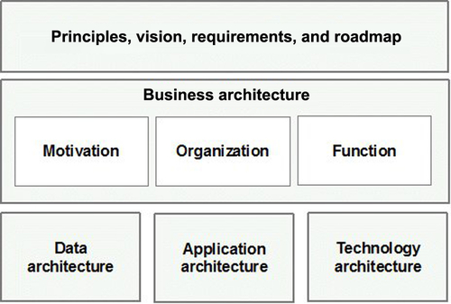
Here we find the four architecture domains (business, data, application, and technology), along with an additional domain (principles, vision, etc.). The business domain is broken down into three subdomains: motivation, organization, and function. Each architectural element belongs to one particular domain according to its nature, as we will see in the following pages.
The metamodel is also organized as follows: a “TOGAF core” part containing fundamental elements and an “extensions” part made up of elements that enrich the core” metamodel with regard to a particular aspect.
3.2.1 The “TOGAF core metamodel”
Figure 3.3 presents the “TOGAF core metamodel” in the form of a simplified UML diagram. The elements of the TOGAF core metamodel are organized using the structure presented earlier, in other words, the four architectural domains (business, data, application, and technology).

• Actor
• Role
• Process
• Function
• Business service
• Data architecture
• Application architecture
• Technology architecture
• Technology component
This breakdown is enriched by the elements used to describe requirements, principles, and the roadmap: principle, constraint, assumption, requirement, gap, work package, and capability.
These elements play a slightly unusual role, inasmuch as they are potentially connected to all the other metamodel elements. These “omnipresent” links simply translate the fact that these elements constitute a set of justifications with regard to the architecture as a whole, and can be used as starting points for maintaining traceability links.
3.2.2 Metamodel extensions
The extensions used to enrich the “TOGAF core metamodel” are organized into several families, each of which adds additional elements to the “core” metamodel. The six extension families are as follows:
• Driver
• Infrastructure consolidation
• Physical application component
• Logical technology component
• Governance
• Contract
• Service quality
• Process modeling
• Control
• Product
• Data modeling
• Physical data component
• Services
The goal of this organization into extension families is to make it easier to adapt the metamodel through the choice of such and such a family according to particular needs. Extensions are added to the “core” metamodel as particular modules, which will extend the vocabulary used.
As an example, Figure 3.4 shows the extensions dedicated to process modeling.

In this case, three elements have been added:
• The event: Enables events linked to processes to be represented, such as the event that triggers a process.
• The control: Typically acts on the execution of a process, by directing it to such and such a branch of the process.
• The product: Represents the input and output of the activities of a process.
This extension mechanism can be used as a means of specializing architecture descriptions within an enterprise. This manner of doing things is one element of the general approach to adapting the TOGAF framework.
Naturally, every element has its place in one of the parts of the general structure, whether it belongs to the TOGAF core metamodel or to one of its extensions. For example, Figure 3.5 shows the distribution of the different elements in the business part and its three subparts (motivation, organization, and function).
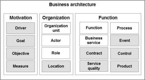
In this schema, gray elements are extension elements, while white elements are “core metamodel” elements.
3.2.3 Conceptual, logical, and physical
As in the previous figure, Figure 3.6 shows the contents of the data architecture, application architecture, and technology architecture domains.

The content of these three domains is relatively similar. Each domain is made up of a conceptual element, a logical element, and a physical element.
3.2.4 Relationship to ADM phases
What links exist between the phases of the ADM and the elements of the metamodel? A first approach, based on the structuring into domains, leads us to consider that there is a link between the breakdown of the metamodel and the three architecture development phases of the ADM (B, C, and D). When we consider that phase C is further broken down into two subphases, we find identical terms, with phases B (Business), C1 (Data), C2 (Application), and D (Technology). However, this equivalence turns out to be more subtle when we consider the elements contained in each domain.
For example, the “data entity” element is naturally positioned in the “data architecture” domain. However, the identification of data entities is a task that belongs to phase B of the ADM, “business architecture,” which produces a model of these entities as output. Moreover, this approach is relevant, since business information (or business objects) is part of the business view of the system, and it would be a mistake to ignore it until phase C (in the “data architecture” subphase).
The “physical application component” element, located in the “application architecture” domain, is not really well located in phase C, which is dedicated to application architecture.2 As a physical element, it is developed in phase D (technology architecture). Here too, the ADM cycle follows a traditional route, dealing first with a logical description, which is translated into technical components during the technology architecture phase (phase D).3
These two examples show that the structure of the two worlds (ADM phases and metamodel domains) does not always exactly match. This may seem surprising, especially as TOGAF tends to bring them together. However, this distinction between phases and architecture domains is realistic. On the one hand, the aim is strict classification; on the other hand, the objective is step-by-step development including all facets and constraints. In this regard, the ADM cycle is inevitably both more complex and more flexible than a formal classification grid, and this is what gives it its agility and efficiency.
3.3 Artifacts
Artifacts designate the representation tools used as a means of communication. They show a part of the architecture in various forms and constitute a major part of the repository.
3.3.1 Viewpoints and views
The concepts of view and viewpoint play a key role in communication on architecture. A viewpoint designates a representational view of the architecture or addresses stakeholder concerns. The viewpoint of a business analyst and that of a project manager are different and require adapted representations. A viewpoint encompasses a collection of views, which define a particular form of representation.
The terms “artifact” and “view” in TOGAF are relatively close in meaning and correspond to a way or visualizing and communicating information captured in the metamodel for specific stakeholder needs. The term “artifact” is a generic concept designating all representations of the architecture, while “views” are organized methodically into “viewpoints.”
3.3.2 Catalogs, matrices, and diagrams
There are three categories of architectural representation forms:
• Catalogs, which are organized lists of elements of the same nature. For example, the catalog of applications or the dictionary of business entities.
• Matrices, which show the relationships that exist between elements: the actors/processes matrix or the data/software components matrix.
• Diagrams, which show a subset of the architecture in the form of a graphical schema. UML diagrams are a good example.
Figure 3.7 shows an example of a diagram. This is a UML class diagram corresponding to a particular view, containing classes with their links but not showing their attributes. In general, other views will be used, for example, to describe all the properties of classes in detail, or conversely to provide a high-level outline of business entities.

We will not go into further detail on these three types here; for more information, readers can refer to Chapters 5 and 6 in which we discuss this subject in detail, notably the major role of diagrams in the representation of enterprise architecture.
3.3.3 The catalog of TOGAF views
By default, TOGAF provides a list of views with a detailed description of their content. The viewpoints used to classify them are simply those of the ADM breakdown. Each phase of the ADM is considered a viewpoint that includes a set of catalog-, matrix-, or diagram-type views.4 For example, the “business” viewpoint, which corresponds to phase B, defines the following views (extract):
• Process flow catalog
• Actor/role matrix
• Functional decomposition diagram
• Process flow diagram
Each viewpoint (vision, business, data, application, etc.) defines the content of its views in the same way. Chapters 7–11 of this book present detailed examples of each of the TOGAF catalog’s views.
This organization into viewpoints associated with ADM phases is highly pertinent, since each phase will consider the architecture from a particular perspective, depending on its objectives. However, in practice, this catalog has to be refined in order to better “suit” the actors (stakeholders) participating in the development of the architecture. This point was already raised during the description of the ADM phases (Section 2.2), which begins by identifying the viewpoints and defining the views that will be used. Naturally, the aim here is not to reinvent the wheel, and this stage will make widespread use of the TOGAF catalog, which, despite being open to criticism, does provide a significant starting point.
How can we build our own catalog of views? By being pragmatic. The main criterion here is efficiency of communication, which can only be developed by closely collaborating with participants, who are the most directly concerned. With this in mind, certain practices will contribute to the quality of the result:
• Start with what already exists, and link it to TOGAF catalog views. It is not unusual to find diagrams that are very similar to the diagrams defined by TOGAF; with just a few adjustments, we can avoid shaking up existing habits.
• Use concrete examples, wherever possible, rather than imposing abstract formulation.
• Communicate widely using different means, and pay close attention to feedback.
In most cases, this catalog can evolve, under the responsibility of the architecture board, which is in charge of validating modifications in order to safeguard its consistency.
3.3.4 Tools and languages
Without going so far as to define a fixed catalog of tools, TOGAF does recommend the use of standards wherever possible. This is notably the case for diagrams, with UML5 and BPMN,6 languages that are widely used in the modeling of information systems and business processes. In practice, enterprises often use a set of various tools: office products, modeling tools, intranet, and so on. However, it is difficult to imagine not having structured tooling to ensure the consistency and management of all the different components of the architecture.
3.4 Building blocks
3.4.1 The game of building
“Building blocks” fundamentally represent the basic bricks that make up the system. More simply put, they satisfy the need to break down all representations of a complex system into subelements. For example, such and such an information system is broken down into domains, then into subsystems, which are themselves further broken down into applications. This example illustrates the composition relationship that exists between “building blocks,” which, like matryoshka dolls, are built by aggregating lower-level “building blocks.” However, this concept is more general, and the breakdown into “building blocks” applies whatever the type of architecture (business, system, or technology). Business processes, architecture foundations, or organizational units are good candidates to become architecture “building blocks.”
TOGAF specifies the characteristics of “building blocks” as follows:
• Corresponds to a set of functions that meet business needs.
• Can be made up of other “building blocks.”
• Interacts with other “building blocks.”
• Can ideally be reused and replaced in the architecture.
The tasks of identifying and defining “building blocks” are central to architecture development, notably information systems. Fundamentally, a system is made up of a collection of interconnected “building blocks.” Depending on the level of detail required, these building blocks “take on board” different types of element. In a large-scale organization, each subsystem can be made up of a set of actors, processes, applications, and technical platforms. If we consider the whole system without going into detail, these subsystems will be considered as “building blocks,” each with a defined scope and defined exchanges between them. At this level, the description remains “black box.” Naturally, other views will have the task of opening these boxes in order to describe the contents of such and such a subsystem in detail.
This way of looking at things is not revolutionary, and seems like simple common sense. The difficulty lies in choosing the best way of breaking down the system, in order to implement all business capabilities within a given timeframe and budget. Furthermore, this is the aim of the ADM method, which provides a structured approach and a set of practices to help the enterprise reach this objective.
“Building blocks” are elements that are conducive to capitalization and reuse. Consequently, they occupy a strategic position in the architecture repository (see Section 4.1).
3.4.2 Architecture building blocks and solution building blocks
We have already mentioned this terminology in Section 1.2.3. As a reminder, TOGAF makes a distinction between architecture building blocks (ABB) and solution building blocks (SBB) in order to separate purely documentary elements from physical components.
3.5 Deliverables
3.5.1 Description and use
Deliverables play a special role in the progress of an ADM cycle. The approval of deliverables by stakeholders establishes formal consensus and defines a state of results from which future work can be carried out. This does not mean that each deliverable is provided and validated by one single phase. On the contrary, many deliverables are developed over the course of several phases, each progressively adding to and consolidating the deliverable in question. In this case, deliverables can be viewed as the gateways that involve the review and acceptance of outputs from one phase/activity as input into the next. This is the case for the “architecture definition document,” whose different parts are developed during phases B, C, and D for the chapters dedicated to business architecture, system architecture, and technology architecture, respectively.
Deliverables are mostly documents, put together from architecture elements, “building blocks,” and artifacts. However, certain deliverables are represented directly by models. This is the case for the “ABB” deliverable, whose aim is to formalize an architecture model.
TOGAF defines 22 deliverables and provides a description and a template for each. As an example, the template for the “architecture definition document” deliverable presents as follows:
• Goals and constraints
• Architecture principles
• Baseline architecture
• Architecture models
• Business architecture models
• Data architecture models
• Application architecture models
• Technology architecture models
• Rationale and justification for architectural approach
• Mapping to the architecture repository
• Mapping to the architecture landscape
• Mapping to reference models
• Mapping to standards
• Reuse assessment
• Gap analysis
• Impact assessment
As we can see (and possibly regret), TOGAF provides a highly succinct description of the document template. It is described more as a typical table of contents, which must be further specified if it is to be effectively used within a particular organization.
Note that this deliverable includes several diagrams from business, application, and technological models.
3.5.2 Deliverables and ADM phases
Table 3.1 presents the main deliverables resulting from the different ADM phases.
Table 3.1
Deliverables and ADM Phases
| No. | Deliverable | ADM Phases |
| L01 | Request for Architecture Work | Pr |
| L02 | Architecture Principles | Pr |
| L03 | Tailored Architecture Framework | Pr |
| L04 | Business Principles, Business Goals, and Business Drivers | Pr, A, B |
| L05 | Architecture Vision | A |
| L06 | Statement of Architecture Work | A |
| L07 | Communication Plan | A |
| L08 | Architecture Definition Document | B, C, D |
| L09 | Architecture Requirements Specification | B, C, D, E, F |
| L10 | Architecture Roadmap | B, C, D, E, F |
| L11 | Transition Architecture | E, F |
| L12 | Implementation and Migration Plan | E, F |
| L13 | Architecture contract | F |
| L14 | Capability Assessment | A, E |
| L15 | Compliance Assessment | G |
| L16 | Change Request | H |
In this table, we have chosen to highlight the major deliverables corresponding to each ADM phase, without taking into account possible updates or adjustments that can always occur in other phases.
We have not included the architecture repository in our table. Although TOGAF classifies this as a deliverable, it is rather an information container, which is only validated through the documents that result from its contents (the same is true for ABB and SBB).
Deliverables linked to architecture work management
The Tailored Architecture Framework (L03), developed during the preliminary phase, plays a special role. Typically, it enables the TOGAF framework to be adapted to the enterprise’s context. It is one of the results of the preliminary phase, which initiates the elements that are to be implemented by transformation projects on different levels: approach, contents, repository, and governance.
The Request for Architecture Work (L01), which results from the preliminary phase, triggers the start of a new ADM cycle. Note here that the response may be negative and the enterprise may decide not to start the architecture change ADM cycle (go-no go).
During phase A, the Statement of Architecture Work (L06) describes all the elements necessary to the organization of the ADM cycle, based on the request for architecture work: management, procedures, cycle planning, and scope.
The Communication Plan (L07), also produced in phase A, provides the internal communication framework: means, tools, and procedures.
Deliverables linked to principles, goals, and requirements
The Architecture Principles (L02), defined during the preliminary phase, establish the general architecture principles that apply to all ADM cycles.
The Business Principles, Business Goals, and Business Drivers (L04) specify the context and goals of an ADM cycle. Initialized during the preliminary phase, they are added to and consolidated during phases A and B (vision and business).
Requirements are recorded in the Architecture Requirements Specification document (L09).
Architecture description deliverables
During phase A, the Architecture Vision (L05) initiates future work by providing a macroscopic and cross-organizational view: goals, requirements, baseline, and target architectures.
The Architecture Definition Document (L08) is the main deliverable of the architecture development phases: B (Business), C (Information System), and D (Technology). In particular, it contains information on architecture (baseline and target), gap analysis, and impact analysis.
Deliverables dedicated to architecture transition
The Architecture Roadmap (L10) results from the development phases B, C, and D and establishes the progression of the transition, the definition of each stage, and macroscopic planning. These elements will be defined by the two following deliverables, during phases E and F.
The Transition Architecture (L11) describes the different stages of transition, and the breakdown of work into work packages, each with its content and dependencies. It also details the architecture expected at each stage.
The Implementation and Migration Plan (L12) provides the detailed schedule, implementation project, resources, and budget.
Deliverables linked to implementation
Architecture contracts (L13) formalize implementation project commitments with regard to the architecture board (phase F).
The results of compliance reviews are recorded in the Compliance Assessment document (L15). These reviews are conducted during phase G.
Once the new architecture has been deployed (phase H), Change Requests (L16) can be sent to and assessed by the architecture board.
3.6 Fundamental concepts
The following fundamental concepts were introduced in this chapter:
• Artifact: Means of communication used to present a particular view of the architecture. Artifacts are organized into catalogs, matrices, and diagrams.
• Deliverable: Architectural work product that is contractually specified and formally validated as output of the different ADM phases.
• Metamodel: Describes the basic elements used to build an enterprise’s architecture. The “metamodel” form enables all the elements and all their relationships to be represented through a simplified UML diagram.
• Building block: Essential components of the architecture that constitute its skeleton. Building blocks can be combined with other building blocks to deliver (target architecture).
• Catalog: Structured list made up of comparable objects, used as a reference.
• Matrix: Representation format that shows the relationship between two (or more) architecture elements in the form of a table.
• Diagram: Graphical view representing a part of a model.
• Viewpoint: Designates the most appropriate perspective for an actor or family of actors. A viewpoint is materialized through a certain number of views on the architecture, in the form of diagrams, documents, or other types of representation. A view is “what we see,” whereas a viewpoint is “where we look from.”