Chapter 15. Troubleshooting BGP
This chapter covers the following troubleshooting topics:
• Troubleshooting BGP neighbor relationships
• Troubleshooting BGP route advertisement/origination and receiving
• Troubleshooting a BGP route not installing in routing table
• Troubleshooting BGP when route reflectors are used
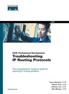
• Troubleshooting outbound traffic flow issues because of BGP policies
• Troubleshooting load-balancing scenarios in small BGP networks
• Troubleshooting inbound traffic flow issues because of BGP policies
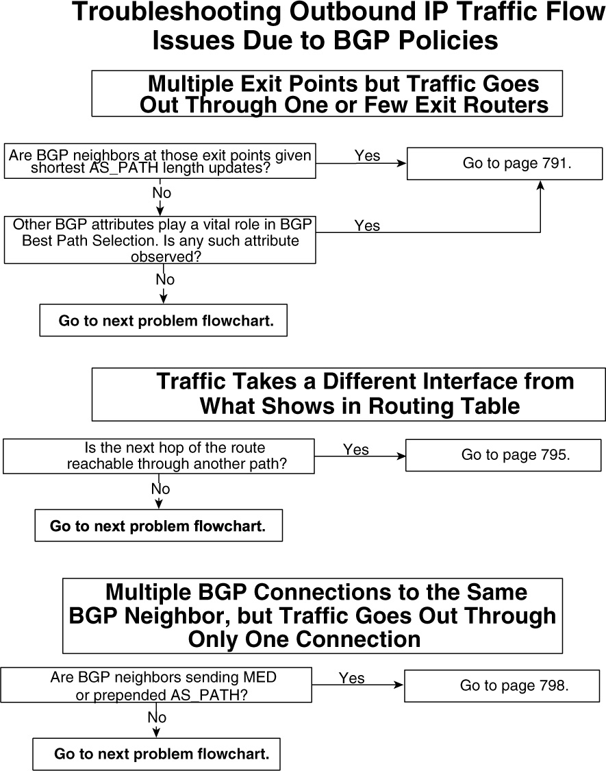
• Troubleshooting BGP best-path calculation issues
• Troubleshooting BGP filtering
This chapter discusses common and efficient real-life techniques to solve problems seen in running BGP networks. Cisco’s implementation of BGP is fairly easy to configure, and robustness of Cisco IOS Software offers BGP operators great flexibility to use BGP to attain the most benefit. However, problems are unavoidable and things go wrong in real networks every day. This chapter offers a simple methodology to tackle problems in networks running BGP.
To troubleshoot BGP-related problems, operators must start from basics. Most of BGP problems are similar to Open System Interconnection (OSI) model problems. For example, BGP neighbor relationship issues should be tackled by looking first at the nature of the neighbor relationship (IBGP or EBGP), followed by the physical connection between two BGP neighbors (OSI Layer 1); then encapsulation issues between neighbors (OSI Layer 2), IP connectivity (OSI Layer 3), and finally TCP connectivity (OSI Layer 4) should be considered. This troubleshooting method offers consistent and accurate resolution to the problem.
Cisco IOS Software debugs should not be run as the first troubleshooting tool. CPU-intensive debugs with a huge amount of data sometimes might not offer any help in troubleshooting a problem; instead, they can cause severe instability to the router.
It is impossible to discuss all BGP-related problems, but this chapter covers most of the problems seen in our real-life experience gained from working with networks running BGP on Cisco devices.
The flowcharts that follow document how to address common problems with BGP with the methodology used in this chapter.
Flowcharts to Solve Common BGP Problems


show and debug Commands for BGP-Related Troubleshooting
Cisco IOS Software offers descriptive show commands and debugs to aid in troubleshooting BGP-related problems. Furthermore, most of the debugs can be run with access lists to limit the output displayed because excessive debug output can severely degrade router performance. Some of the most commonly used show and debug commands in troubleshooting BGP problems in Cisco routers are as follows:
• show ip bgp neighbor [address]
• show ip bgp neighbors [address] [advertised-routes]
• show ip bgp neighbors [routes]
• debug ip bgp update [access-list]
• debug ip bgp neighbor-ip-address updates [access-list]
show ip bgp prefix Command
This is probably the most widely used BGP show command to check the BGP path entry for prefix in BGP table. Among other things, the output shows all BGP attributes assigned to the prefix and all available paths from multiple neighbors.
show ip bgp summary Command
This command gives a summarized list of the status of all BGP neighbors, the number of prefixes received from each peer, and local BGP parameters.
show ip bgp neighbor [address] Command
This command displays details about the BGP neighbor, including its status, the number of updates sent and received, and TCP statistics.
show ip bgp neighbors [address] [advertised-routes] Command
This command displays routes advertised to neighbors and is used in troubleshooting cases when neighbors don’t receive some or all BGP routes.
show ip bgp neighbors [routes] Command
This command displays routes received from neighbors and is used in troubleshooting cases when the local routers don’t receive some or all BGP routes.
debug ip bgp update [access-list] Command
This is the most commonly used BGP debug to troubleshoot problems in BGP path advertisement. The access-list option limits the output display; otherwise, if the number of prefixes is huge, this output can severely degrade router performance and also can reload the router in worst cases. Both standard and extended access lists can be used.
Standard Access List Usage
debug ip bgp update 1
access-list 1 permit host 100.100.100.0
With standard access lists, the host 100.100.100.0 means that if a BGP update contains 100.100.100.0, only the debug displays the output. Unlike extended access lists, standard access lists do not give any option to limit the output based on the mask of the prefix.
Extended Access List Usage
debug ip bgp update 101
access-list 101 permit ip host 100.100.100.0 host 255.255.255.0
For the preceding extended access list, only BGP updates related to 100.100.100.0/24 display. The first portion of the access list, host 100.100.100.0, means that the prefix to display output is 100.100.100.0. The second portion, host 255.255.255.0, requires the mask of 100.100.100.0 to be Class C 255.255.255.0 (/24).
debug ip bgp neighbor-ip-address updates [access-list] Command
This debug command is similar to the previous one, except that it gives the option of displaying debug output on a per-neighbor basis.
Troubleshooting BGP Neighbor Relationships
This section discusses the most common issues in forming a neighbor relationship between two BGP-speaking routers. BGP speakers exchange routing information only after they successfully become neighbors with each other. Troubleshooting neighbor relationship issues should follow the OSI reference model. First, you should check Layer 2 connectivity; then check IP connectivity (Layer 3), TCP connections (Layer 4), and finally the BGP configuration in Cisco IOS Software.
The section is arranged to discuss external BGP neighbors’ issues, internal BGP neighbors, and then problems that are common in both external and internal BGP neighbor relationships.
The following is the list of problems most commonly seen when forming BGP neighbor relationships.
• Directly connected external BGP neighbors not initializing
• Nondirectly connected external BGP neighbors not initializing
• Internal BGP neighbors not initializing
• BGP neighbors (external and internal) not initializing
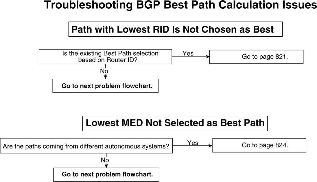
Problem: Directly Connected External BGP Neighbors Not Initializing
This section discusses issues when a directly connected EBGP neighbor relationship is unsuccessful. The autonomous system (AS) will not send or receive any IP prefix updates to or from a neighboring AS unless the neighbor relationship reaches the Established state, which is the final stage of BGP neighbor establishment, as described in Chapter 14, “Understanding Border Gateway Protocol Version 4 (BGP-4).” When an AS has a single EBGP connection, no IP connectivity can occur until BGP finalizes its operation of sending and receiving IP prefixes.
Figure 15-1 shows a network in which an external BGP neighbor relationship is configured between AS 109 and AS 110.

Figure 15-1 External BGP Neighbor Relationship
The most common possible causes of this problem are as follows:
• Layer 2 is down, preventing communication with a directly connected EBGP neighbor.
• An incorrect neighbor IP address is in the BGP configuration.
Directly Connected External BGP Neighbors Not Coming Up—Cause: Layer 2 Is Down, Preventing Communication with Directly Connected BGP Neighbor
IP connectivity cannot occur until Layer 2 in the OSI reference model is up. Whether this Layer 2 information is learned dynamically or is configured statically, each router must have a correct Layer 2 rewrite information of adjacent routers. Ethernet, Frame Relay, ATM, and so on are most commonly used Layer 2 technologies. Most network administrators configure Layer 2 parameters in router configurations correctly; sometimes, basic cabling issues also can cause Layer 2 issues. Among cabling issues, misconfiguration in router configuration can cause ARP, DLCI mapping, and VPI/VIC encapsulation failures, which are the most common Layer 2 failures. It is beyond the scope of this book to address how this Layer 2 information is obtained. Case(s) in this section try to address how to troubleshoot BGP problems when the cause of the EBGP neighbor relationship failure is Layer 2.
Figure 15-2 shows the flowchart to follow to fix this problem.

Figure 15-2 Problem-Resolution Flowchart
Debugs and Verification
Example 15-1 shows the relevant configuration of R1 and R2, respectively.
Example 15-1 R1 and R2 Configuration
R1#router bgp 109
neighbor 131.108.1.2 remote-as 110
interface Ethernet0
ip address 131.108.1.1 255.255.255.0
R2#router bgp 110
neighbor 131.108.1.1 remote-as 109
interface Ethernet0
ip address 131.108.1.2 255.255.255.0
You can verify the BGP neighbor relationship on Cisco IOS Software by using the commands in Example 15-2.
Example 15-2 Verifying BGP Neighbor Relationship
R1#show ip bgp summary
BGP router identifier 206.56.89.6, local AS number 109
BGP table version is 1, main routing table version 1
Neighbor V AS MsgRcvd MsgSent TblVer InQ OutQ Up/Down State/PfxRcd
131.108.1.2 4 110 3 7 0 0 0 00:03:14 Active
R1#show ip bgp neighbors 131.108.1.2
BGP neighbor is 131.108.1.2, remote AS 110, external link
BGP version 4, remote router ID 0.0.0.0
BGP state = Active
Last read 00:04:23, hold time is 180, keepalive interval is 60
seconds
Received 3 messages, 0 notifications, 0 in queue
Sent 7 messages, 1 notifications, 0 in queue
Route refresh request: received 0, sent 0
Minimum time between advertisement runs is 30 seconds
For address family: IPv4 Unicast
BGP table version 1, neighbor version 0
Index 1, Offset 0, Mask 0x2
0 accepted prefixes consume 0 bytes
Prefix advertised 0, suppressed 0, withdrawn 0
Connections established 1; dropped 1
Last reset 00:04:44, due to BGP Notification sent, hold time expired
No active TCP connection
The output in Example 15-2 shows that the BGP neighbor is in the Active state. This state indicates that no successful communication between the neighbors has taken place and that BGP has failed to form neighbor relationship.
You can use ping to verify IP connectivity between R1 and R2. Example 15-3 shows that R1 cannot ping R2’s IP address.
Example 15-3 R1 Ping of R2’s IP Address Fails
R1#ping 131.108.1.2
Type escape sequence to abort.
Sending 5, 100-byte ICMP Echos to 131.108.1.2, timeout is 2 seconds:
.....
Success rate is 0 percent (0/5)
Solution
In this example, the ping failure from R1 to R2 was the result of Layer 2 on R2 being down. Example 15-4 shows the output indicating a Layer 2 problem.
Example 15-4 show interface Command Output Pinpoints That This Is a Layer 2 Problem
R2# show interface ethernet 0
Ethernet0 is down, line protocol is down
This might be because of cable issues or a hardware problem.
Apart from the interface being down, as in Example 15-4, Layer 2 encapsulation failure can also cause IP connectivity to break. Layer 2 encapsulation failure can occur because of corruption in the ARP table in case of Ethernet or an incorrect DLCI–VPI/VCI mapping in cases of Frame Relay and ATM, respectively. Fixing these should enable basic IP connectivity, and the BGP neighbor relationship should initialize.
Directly Connected External BGP Neighbors Not Coming Up—Cause: Incorrect Neighbor IP Address in BGP Configuration
Figure 15-3 shows the flowchart to follow to fix this problem.
Figure 15-3 Problem-Resolution Flowchart
Debugs and Verification
Example 15-5 shows the relevant configuration of R1 and R2, respectively.
Example 15-5 R1 and R2 Configuration
R1# router bgp 109
neighbor 131.108.1.2 remote-as 110
interface Ethernet0
ip address 131.108.1.1 255.255.255.0
R2# router bgp 110
neighbor 131.108.1.11 remote-as 109
interface Ethernet0
ip address 131.108.1.2 255.255.255.0
Misconfiguration of the neighbor address is a fairly common mistake, and it can be caught with visual inspection of the configuration. However, in a large IP network, this might not be a trivial task. Example 15-6 shows how to capture this mistake using debugs in Cisco IOS Software.
Example 15-6 debug ip bgp Command Output Helps Pinpoint Incorrectly Configured Neighbor Addresses
R2#debug ip bgp
BGP debugging is on
R2#
Nov 28 13:25:12: BGP: 131.108.1.11 open active, local address 131.108.1.2
Nov 28 13:25:42: BGP: 131.108.1.11 open failed: Connection timed out; remote host
not responding
The output in Example 15-6 clearly points out that R2 is having difficulty communicating with host 131.108.1.11.
Solution
The correct neighbor address should be configured when establishing BGP neighbor relationship. Therefore, R2’s BGP configuration must look like Example 15-7.
Example 15-7 Correcting R2’s BGP Configuration
R2# router bgp 110
neighbor 131.108.1.1 remote-as 109
A similar problem can occur when the incorrect AS number is configured.
Problem: Nondirectly Connected External BGP Neighbors Not Coming Up
As discussed in Chapter 14, in some cases, EBGP neighbors are not directly connected. BGP neighbor relationships can be established in the following situations as well:
• Between loopback interfaces of two routers.
• Between routers trying to make EBGP neighbor relationship that are separated by one or more routers. Such a neighbor relationship is termed EBGP multihop in Cisco IOS Software.
EBGP multihop can be used for several reasons. Peering between loopbacks between EBGP typically is done when multiple interfaces exist between the routers, and IP traffic needs to be load-shared among those interfaces. Another scenario might be one in which an edge router cannot run BGP and, therefore, EBGP must be run between a nonedge device in one AS and an edge router in another.
A neighbor relationship must be established before any BGP updates and IP traffic can flow from one AS to another. This section addresses most of the common causes in which nondirectly connected EBGP neighbor relationships won’t establish.
Figure 15-4 shows that AS 109 and AS 110 are forming an EBGP neighbor relationship between the loopback interfaces. Such a connection will be considered nondirectly connected.

Figure 15-4 Nondirectly Connected EBGP Session Between the Loopback Interfaces
The most common possible causes of this problem are as follows:
• The route to the nondirectly connected peer address is missing from the routing table.
• The ebgp-multihop command is missing in BGP configuration.
• The update-source interface command is missing.
Nondirectly Connected External BGP Neighbors Not Coming Up—Cause: Route to the Nondirectly Connected Peer Address Is Missing from the Routing Table
Figure 15-5 shows the flowchart to follow to fix this problem.

Figure 15-5 Problem-Resolution Flowchart
When BGP tries to peer the neighbor relationship with IP addresses that are not directly connected, as shown in Figure 15-4, the IP routing table must have the route to that IP address.
In Figure 15-4, R1 is configured to peer with Loopback 0 of R2, and R2 is configured to peer with Loopback 0 of R1. This is a common practice when multiple connections exist between R1 and R2 and load sharing over these multiple lines is required.
Debugs and Verification
Example 15-8 shows the relative configuration of both Routers R1 and R2.
Example 15-8 Configurations for R1 and R2 in Figure 15-4
R1# router bgp 109
neighbor 131.108.10.2 remote-as 110
neighbor 131.108.10.2 ebgp-multihop 2
neighbor 131.108.10.2 update-source Loopback0
R2# router bgp 110
neighbor 131.108.10.1 remote-as 109
neighbor 131.108.10.1 ebgp-multihop 2
neighbor 131.108.10.1 update-source Loopback0
In Example 15-8, Routers R1 and R2 are configured to peer with each other’s loopback IP address. ebgp-multihop 2 means that R1 and R2 peering addresses could be two hops away. update-source means that the source of BGP packets is the Loopback the 0 IP address because both routers accept only BGP packets sourced with the Loopback 0 IP address of other router.
The output in Example 15-9 shows the neighbor relationship between R1 and R2.
Example 15-9 show ip bgp Command Output Displays the BGP Neighbor Relationship Between R1 and R2
R1#show ip bgp summary
BGP router identifier 131.108.10.1, local AS number 109
BGP table version is 1, main routing table version 1
Neighbor V AS MsgRcvd MsgSent TblVer InQ OutQ Up/Down State/PfxRcd
131.108.10.2 4 110 3 3 0 0 0 00:03:21 Active
R1#show ip bgp neighbors 131.108.10.2
BGP neighbor is 131.108.10.2, remote AS 110, external link
BGP version 4, remote router ID 0.0.0.0
BGP state = Active
Last read 00:04:20, hold time is 180, keepalive interval is 60 seconds
Received 3 messages, 0 notifications, 0 in queue
Sent 3 messages, 0 notifications, 0 in queue
Route refresh request: received 0, sent 0
Minimum time between advertisement runs is 30 seconds
For address family: IPv4 Unicast
BGP table version 1, neighbor version 0
Index 2, Offset 0, Mask 0x4
0 accepted prefixes consume 0 bytes
Prefix advertised 0, suppressed 0, withdrawn 0
Connections established 1; dropped 1
Last reset 00:04:21, due to User reset
External BGP neighbor may be up to 2 hops away.
No active TCP connection
The highlighted output in Example 15-9 shows that R1’s neighbor relationship with R2 is in the Active state and that the BGP relationship is not complete.
The configuration shown in Example 15-8 is a required configuration when configuring an EBGP connection to a nondirectly connected peer; however, one thing that is not controlled by BGP configuration is the reachability to peer addresses.
Example 15-10 shows that R1 cannot reach the loopback interface of R2 because R1 does not have the route to reach R2.
Example 15-10 R1 Cannot Ping R2’s Loopback Interface and Has No Route to Reach R2
R1#ping 131.108.10.2
Type escape sequence to abort.
Sending 5, 100-byte ICMP Echos to 131.108.10.2, timeout is 2 seconds:
.....
Success rate is 0 percent (0/5)
R1#show ip route 131.108.10.2
% Subnet not in table
In R1, BGP will send its packets to peer 131.108.10.2, but packets will be dropped by R1 because no routing reachability is available for 131.108.10.2.
Solution
BGP relies on an IP routing table to reach a peer address. In the example in Figure 15-4, R1 must have a route to the loopback interface of R2, and R2 must have a route to the loopback interface of R1. It is irrelevant how the route to the peer address is learned, as long as the route is present in the routing table. Administrators of R1 and R2 can choose to run a dynamic IP routing (an IGP) between each other (for example, using OSPF), or they could nail a static route to each other. Using a static route is a common practice. A simple rule of thumb is that R1 and R2 must have most specific routes for each other’s loopback addresses through any other protocol other than BGP.
To configure a static route on R1 to reach multihop EBGP neighbors, you would enter the following:
ip route 131.108.10.2 255.255.255.255 131.108.1.2
R1 has a host static route for R2’s loopback interface with a next hop of 131.108.1.2, which is R2’s Ethernet interface IP address. Similarly, R2 should have a static route for R1’s loopback interface. This will ensure that both routers have reachability to multihop EBGP neighbors.
Nondirectly Connected External BGP Neighbors Not Coming Up—Cause: ebgp-multihop Command Is Missing in BGP Configuration
Figure 15-6 shows the flowchart to follow to fix this problem.
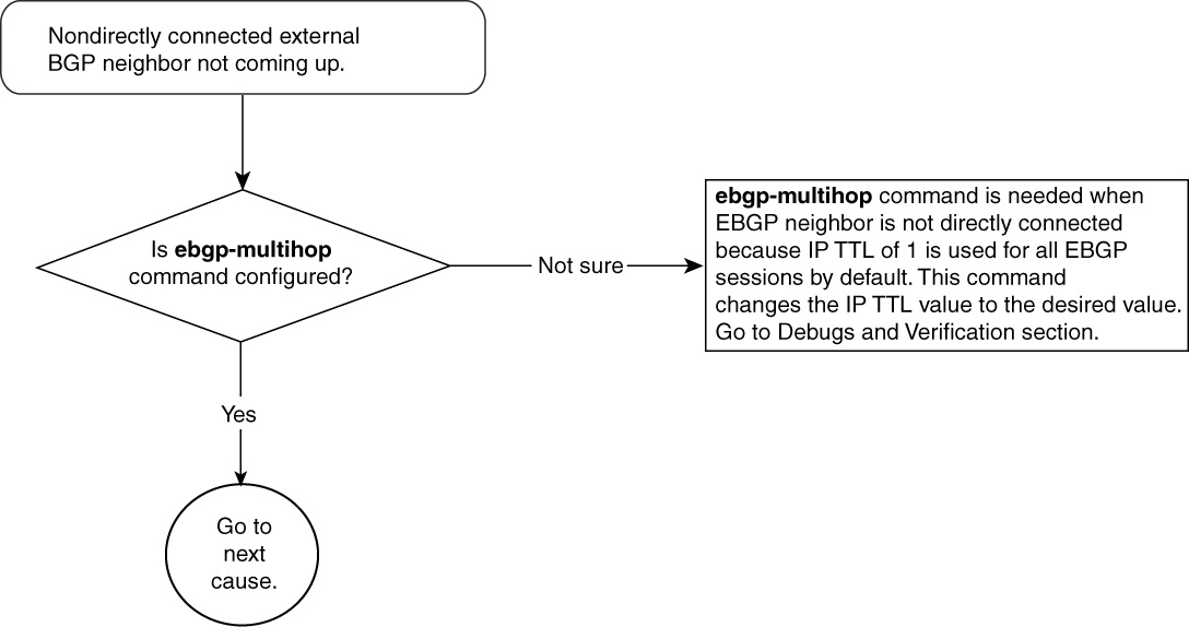
Figure 15-6 Problem-Resolution Flowchart
By default, in Cisco IOS Software, BGP packets sent to an external BGP neighbor have their IP Time To Live (TTL) set to 1. If an EBGP neighbor is not directly connected, the first device in the path will drop BGP packets with TTL equal to 1 to that EBGP neighbor.
Debugs and Verification
Returning to the network in Figure 15-4, R1 is trying to peer EBGP to R2’s Loopback 0 interface, which is considered more than one hop away. Example 15-11 shows the configuration of R1.
Example 15-11 R1’s Configuration to Form EBGP Multihop Neighbor Relationship
R1# router bgp 109
neighbor 131.108.10.2 remote-as 110
neighbor 131.108.10.2 update-source Loopback0
Example 15-12 shows the output to verify that nondirectly connected EBGP neighbors are either coming up or not coming up.
Example 15-12 show ip bgp Command Output Verifies if the EBGP Neighbors Are Coming Up
R1#show ip bgp summary
BGP router identifier 131.108.10.1, local AS number 109
BGP table version is 1, main routing table version 1
Neighbor V AS MsgRcvd MsgSent TblVer InQ OutQ Up/Down State/PfxRcd
131.108.10.2 4 110 25 25 0 0 0 00:00:51 Idle
R1#show ip bgp neighbors 131.108.10.2
BGP neighbor is 131.108.10.2, remote AS 110, external link
BGP version 4, remote router ID 0.0.0.0
BGP state = Idle
Last read 00:00:15, hold time is 180, keepalive interval is 60 seconds
Received 25 messages, 0 notifications, 0 in queue
Sent 25 messages, 0 notifications, 0 in queue
Route refresh request: received 0, sent 0
Minimum time between advertisement runs is 30 seconds
For address family: IPv4 Unicast
BGP table version 1, neighbor version 0
Index 2, Offset 0, Mask 0x4
0 accepted prefixes consume 0 bytes
Prefix advertised 0, suppressed 0, withdrawn 0
Connections established 4; dropped 4
Last reset 00:02:18, due to User reset
External BGP neighbor not directly connected.
No active TCP connection
The highlighted output shows that BGP neighbor is in the Idle state, in which no resources are allocated to BGP neighbor. This might be because the other side has not received any BGP negotiation from R1 or because R1 has not received anything from R2.
Solution
Use the ebgp-multihop command to increase the IP TTL value to the desired number. Example 15-13 shows the required configuration on R1 to bring up the EBGP neighbor R2.
Example 15-13 Using ebgp-multihop to Increase the IP TTL Value
R1# router bgp 109
neighbor 131.108.10.2 remote-as 110
neighbor 131.108.10.2 ebgp-multihop 2
neighbor 131.108.10.2 update-source Loopback0
The ebgp-multihop 2 command sets the IP TTL value to 2 rather than the default of 1. This way, if a BGP speaker is two hops away, the BGP packet will reach it; otherwise, it would have been dropped by the intermediate device because of the IP TTL expiration.
Example 15-15 shows the debug ip packet output and sniffer capture in R2 of BGP packets from R1 to R2. ebgp-multihop is set to 5, as shown in the configuration of Example 15-14.
Example 15-14 Setting ebgp-multihop to 5
R1# router bgp 109
neighbor 131.108.10.2 remote-as 110
neighbor 131.108.10.2 ebgp-multihop 5
neighbor 131.108.10.2 update-source Loopback0
Example 15-15 debug ip packet and Sniffer Capture in R2 of BGP Packets from R1 to R2
IP: s=131.108.10.1 (Ethernet0), d=131.108.10.2, len 59, rcvd 4
TCP src=179, dst=13589, seq=1287164041, ack=1254239588, win =16305 ACK
04009210: 0000 0C47B947 00000C09 ...G9G....
04009220: 9FEA0800 45C00028 00060000 04 069B2F .j..E@.(......./
04009230: 836C0A01 836C0A02 00B33515 4CB89089 .l...l...35.L8..
04009240: 4AC22D64 50103FB1 CA170000 00000000 JB-dP.?1J.......
04009250: 0000C8 ..H
The debug shows that R2 is receiving a BGP packet on TCP port 179 from source 131.108.10.1 (R1). In the sniffer capture, the highlighted hex value 04 is the IP TTL value of 4. The IP TTL value is 4 because R2 decremented the TTL by 1. This example of capturing packets through sniffer is shown to illustrate the use of the ebgp-multihop command in BGP to increase the IP TTL of a BGP packet.
Nondirectly Connected External BGP Neighbors Not Coming Up—Cause: update-source interface Command Is Missing
By default in Cisco IOS Software, the source of the BGP packet is the outgoing interface IP address as taken from the routing table.
In BGP, the neighbor’s IP address must be statically defined in configuration. If an EBGP speaker does not receive a BGP update from a IP source that is identical to what it has configured, it rejects that update. The update-source command in BGP changes the source address of the IP packet. Instead of picking the outgoing interface as a source IP address, BGP packets will be sourced with the interface IP address configured with the update-source command.
Figure 15-7 shows the flowchart to follow to fix this problem.
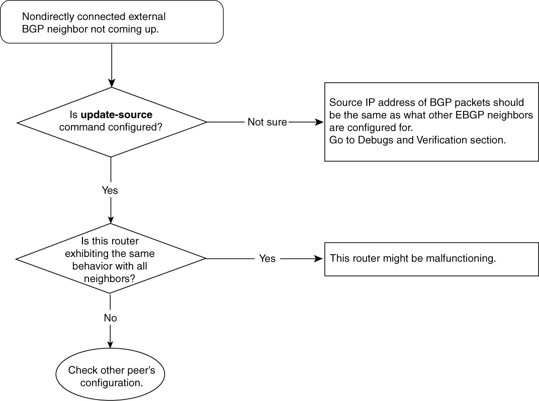
Figure 15-7 Problem-Resolution Flowchart
Debugs and Verification
Example 15-16 displays output from R1 to shows R1’s IP routing table entry for R2’s loopback 131.108.10.2 and R1’s outgoing interface address to reach R2’s loopback interface.
Example 15-16 R1 IP Routing Table Entry for R2’s Loopback Interface
R1#show ip route 131.108.10.2
Routing entry for 131.108.10.2/32
Known via "static", distance 1, metric 0
Routing Descriptor Blocks:
* 131.108.1.2
Route metric is 0, traffic share count is 1
R1#show ip route 131.108.1.2
Routing entry for 131.108.1.0/24
Known via "connected", distance 0, metric 0 (connected, via interface)
Routing Descriptor Blocks:
* directly connected, via Ethernet0
Route metric is 0, traffic share count is 1
R1#show interfaces ethernet 0
Ethernet0 is up, line protocol is up
Hardware is Lance, address is 0000.0c09.9fea (bia 0000.0c09.9fea)
Internet address is 131.108.1.1/24
All IP packets destined for 131.108.10.2 have a source address of 131.108.1.1, which is the outgoing interface address of R1, as shown in Example 15-16.
Example 15-17 shows a simple BGP configuration of R1 and R2 (as depicted in the network in Figure 15-4), peering with each other’s loopback. The configuration in Example 15-17 does not result in an EBGP neighbor relationship because the IP source address of BGP packets won’t be what R2 is configured to expect. The working configuration is shown in the “Solution” section.
Example 15-17 R1/R2 BGP Configuration with Peering with Loopback Interfaces
R1# router bgp 109
neighbor 131.108.10.2 remote-as 110
neighbor 131.108.10.2 ebgp-multihop 2
R2# router bgp 110
neighbor 131.108.10.1 remote-as 109
neighbor 131.108.10.1 ebgp-multihop 2
The problem comes in when R1 sends its BGP packets to its configured neighbor 131.108.10.2. The source IP address of those BGP packets will be 131.108.1.1, the outgoing interface address. R2 is expecting BGP packets from R1 with the source address of R1’s loopback 131.108.10.1, the peering address, so it will reject these BGP packets.
Example 15-18 shows the output of the debug ip bgp that shows how R2 rejects packets from R1.
Example 15-18 debug ip bgp Command Output Reveals R2 Rejecting Packets from R1
R1#debug ip bgp
04:42:10: BGP: 131.108.10.2 open active, local address 131.108.1.1
04:42:10: BGP: 131.108.10.2 open failed: Connection refused by remote host
Solution
R1 should be configured with the update-source command, using the neighbor statement for R2 to accept any BGP packets from R1. The update-source command ensures that the source address is that of Loopback 0, which R2 expects. Example 15-19 shows the necessary configuration addition in R1 and R2 to form an EBGP multihop neighbor relationship.
Example 15-19 Correct Configuration of R1 and R2 to Form EBGP Multihop Neighbor Relationship
R1# router bgp 109
neighbor 131.108.10.2 remote-as 110
neighbor 131.108.10.2 ebgp-multihop 2
neighbor 131.108.10.2 update-source Loopback0
R2# router bgp 110
neighbor 131.108.10.1 remote-as 109
neighbor 131.108.10.1 ebgp-multihop 2
neighbor 131.108.10.1 update-source Loopback0
Problem: Internal BGP Neighbors Not Coming Up
IBGP can experience issues similar to EBGP in neighbor relationship. IBGP is an important piece of overall BGP-running networks. Chapter 14 discusses the importance and usage of IBGP. This section addresses some commonly seen issues exclusive to IBGP neighbor relationship problems. The causes of this problem are identical to the previous problem of nondirectly connected external BGP neighbors not coming up:
• The route to the nondirectly connected IBGP neighbor address is missing.
• The update-source interface command is missing in BGP configuration.
You can use the same troubleshooting and configuration techniques as those used for the EBGP problem.
Problem: BGP Neighbors (External and Internal) Not Coming Up—Cause: Interface Access List Blocking BGP Packets
Interface access list/filters are another common cause of BGP neighbor activation problems. If an interface access list unintentionally blocks TCP packets that carry BGP protocol packets, the BGP neighbor will not come up.
Figure 15-8 shows the flowchart to follow to fix this problem.
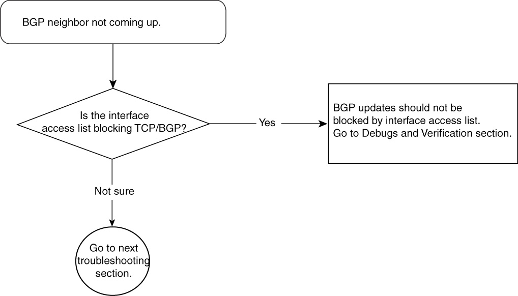
Figure 15-8 Problem-Resolution Flowchart
Debugs and Verification
Example 15-20 shows sample access list 101 that explicitly blocks TCP. Example 15-20 shows access list 102 that has an implicit deny of BGP because Cisco IOS Software has an implicit deny at the end of each access list.
Both access lists 101 and 102 will prevent a BGP neighbor relationship from coming up.
Example 15-20 Access List Configuration Blocking BGP Neighbors
R1#access-list 101 deny tcp any any
access-list 101 deny udp any any
access-list 101 permit ip any any
interface ethernet 0
ip access-group 101 in
access-list 102 permit udp any any
access-list 102 permit ospf any any
interface ethernet 0
ip access-group 102 in
Solution
An interface access list must permit the BGP port (TCP port 179) explicitly or implicitly to allow neighbor relationships.
Example 15-21 shows the revised access list configuration that allows BGP.
Example 15-21 Access List Configuration Permitting BGP
R1#no access-list 101
access-list 101 deny udp any any
access-list 101 permit tcp any any eq bgp
access-list 101 permit ip any any
All BGP packets will be permitted because of the second line in access list 101.
Troubleshooting BGP Route Advertisement/Origination and Receiving
Another common problem after neighbor relationship issues that BGP operators face occurs in BGP route advertisement/origination and receiving. BGP originates routes only by configuration. However, it needs no configuration in receiving routes.
Larger ISPs originate new BGP routes for their customers on a daily basis, whereas small-enterprise BGP networks mostly configure BGP route origination upon first setup. Problems in route originating can occur because of either configuration mistakes or a lack of BGP protocol understanding. This section addresses a mix of simple and complicated problems seen in BGP route advertisement/origination and receiving.
The following is a list of problems discussed in this section related to BGP route originating and advertisement:
• A BGP route not getting originated
• Problem in propagating/originating a BGP route to IBGP/EBGP neighbors
• Problem in propagating a BGP route to an IBGP neighbor but not to an EBGP neighbor
• Problem in propagating an IBGP route to an IBGP/EBGP neighbor
Problem: BGP Route Not Getting Originated
BGP originates IP prefixes and announces them to neighboring BGP speakers (IBGP and EBGP) so that the Internet can reach those prefixes. For example, if an IP address associated with www.cisco.com fails to originate because of a BGP configuration mistake or a lack of protocol requirements, the Internet will never know about the IP address of www.cisco.com, resulting in no connectivity to this web site. Therefore, it is essential to look at BGP route-origination issues in detail. Several causes in failure of BGP route origination exist, the most common of which are as follows:
• The IP routing table does not have a matching route.
• A configuration error has occurred.
• BGP is autosummarizing to a classful/network boundary.
BGP Route Not Getting Originated—Cause: IP Routing Table Does Not Have a Matching Route
BGP requires the IP routing table to have an exact matching entry for the prefix that BGP is trying to advertise using network and redistribute command. The prefix and mask of the network that BGP is trying to advertise must be identical in the IP routing table and in the BGP configuration. BGP will fail to originate any prefix related to this network if this discrepancy exists.
Figure 15-9 shows the flowchart to follow to fix this problem.
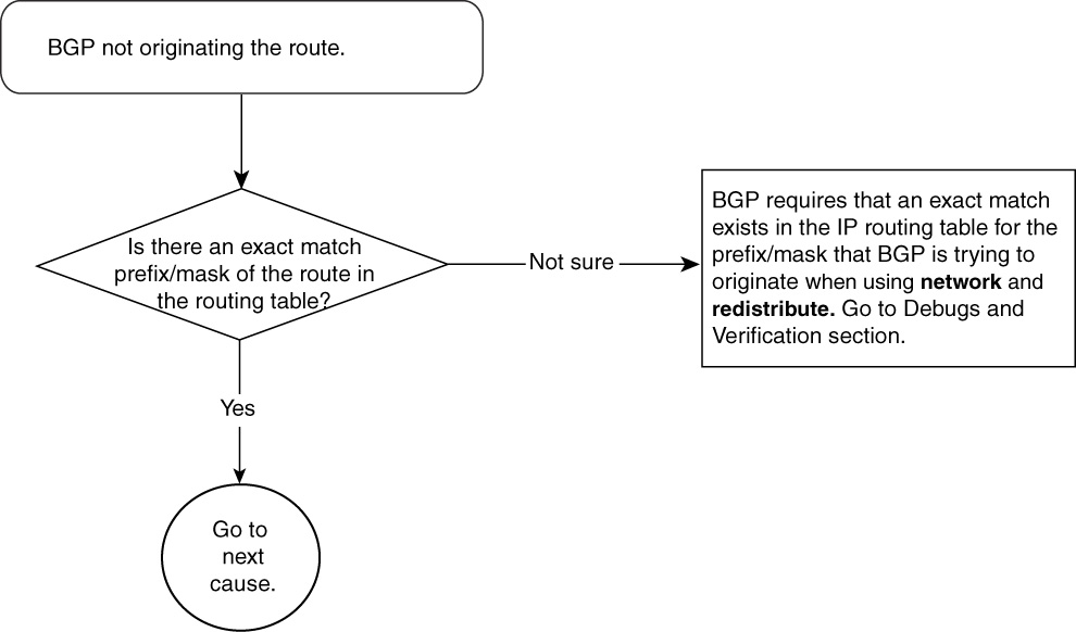
Figure 15-9 Problem-Resolution Flowchart
Debugs and Verification
This section assumes that there are no mistakes in BGP configuration.
Case 1: Matching Route Does Not Exist in the Routing Table
Example 15-22 shows that BGP is configured to advertise 100.100.100.0/24 but fails to do so because the routing table does not contain an exact match for the prefix advertised.
Example 15-22 Routing Table Lacks the Exact Prefix That BGP Is Trying to Advertise
router bgp 109
no synchronization
network 100.100.100.0 mask 255.255.255.0
neighbor 131.108.1.2 remote-as 109
R1#show ip route 100.100.100.0
% Network not in table
R1#show ip bgp 100.100.100.0
% Network not in table
BGP does not consider 100.100.100.0/24 as a candidate to advertise because its exact match does not exist in the IP routing table. The highlighted portion of Example 15-22 shows that the IP routing table does not have 100.100.100.0/24; therefore, BGP failed to create an entry even though it was properly configured.
Case 2: Route Exists in the IP Routing Table but Masks Differ from What Is in the IP Routing Table and What Is in the BGP Configuration
This is another scenario in which BGP fails to originate an IP prefix, even with proper configuration. The BGP configuration is the same as the configuration in Example 15-22. Example 15-23 shows a mismatch between the prefix mask in the IP routing table entry and the BGP configuration.
Example 15-23 Mismatch Between Prefix Mask in IP Routing Table Entry and BGP Configuration
R1#show ip route 100.100.100.0
Routing entry for 100.100.100.0/23
Known via "static", distance 1, metric 0 (connected) Routing Descriptor Blocks:
* directly connected, via Null0
Route metric is 0, traffic share count is 1
R1#show ip bgp 100.100.100.0
% Network not in table
Again, BGP does not consider 100.100.100.0/24 as a candidate to advertise. Although the route exists in the IP routing table, the mask differs. The IP routing table entry for 100.100.100.0 has a mask of /23, whereas BGP configuration has a mask of /24.
The advertised BGP route must appear in the BGP table of the originator router before receipt by BGP neighbors.
Solution
Identical advertising BGP routes must exist in the IP routing table when network and redistribute commands are used. The IP routing table learns such routes either dynamically through a routing protocol or by a static route.
Commonly, BGP operators define a static route for the prefix being advertised. This way, the IP routing table is guaranteed to have a valid IP routing table entry of the advertised prefix.
To advertise 100.100.100.0/24, for example, a sample static route and corresponding BGP would look like Example 15-24.
Example 15-24 Static Route Configuration to Match BGP Advertisement
ip route 100.100.100.0 255.255.255.0 null 0
router bgp 109
network 100.100.100.0 mask 255.255.255.0
As Example 15-24 demonstrates, null 0 is used as a next hop of the static route. No traffic should ever follow this static route because it will be sent to the bit bucket. It is assumed that a more specific route of 100.100.100.0/24 exists in the IP routing table.
BGP Route Not Getting Originated—Cause: Configuration Error
Configuration mistakes often cause BGP failure to advertise IP prefixes. Multiple ways to originate IP prefixes in BGP exist, and each method requires strict syntax in configuration. Therefore, it is essential that BGP operators thoroughly understand Cisco IOS Software configuration guidelines.
Figure 15-10 shows the flowchart to follow to fix this problem.
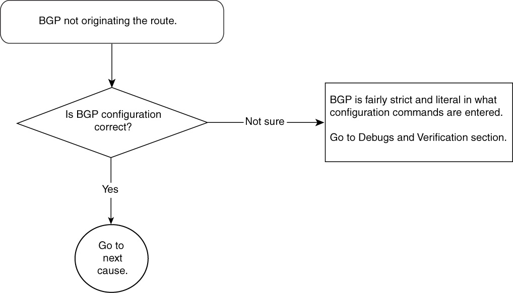
Figure 15-10 Problem-Resolution Flowchart
Debugs and Verification
Three ways exist to originate prefixes in BGP:
• Use a network statement.
• Use an aggregate statement.
• Redistribute other protocol/static routes in BGP.
In Cisco IOS Software, BGP requires the configuration to have proper BGP syntax and commands to advertise any route to IBGP/EBGP neighbors.
Cases 1, 2, and 3 that follow show misconfiguration of BGP in advertising 100.100.100.0/24 in all methods.
Case 1: BGP Prefix Origination with the network Statement
Example 15-25 shows a misconfiguration in BGP to advertise 100.100.100.0/24 using the network statement.
Example 15-25 Improperly Configuring BGP to Advertise 100.100.100.0/24 Using the network Statement
router bgp 109
no synchronization
network 100.100.100.0 mask 255.255.255.0
neighbor 131.108.1.2 remote-as 109
ip route 100.100.100.0 255.255.254.0 null 0
The static route for 100.100.100.0 has a mask of /23, whereas BGP is configured to advertise /24. Therefore, BGP will not consider /24 as a valid advertisement because an exact match does not exist in the routing table.
Case 2: BGP Prefix Origination with the aggregate-address Command
Example 15-26 shows the correct configuration of BGP to advertise 100.100.100.0/24, but this configuration fails to create an advertisement in BGP. The explanation behind this failure is that the aggregate-address configuration requires the BGP table to contain at least one route that is more specific than the aggregate.
Example 15-26 Configuring BGP to Advertise 100.100.100.0/24 Using the aggregate-address Statement
router bgp 109
no synchronization
aggregate-address 100.100.100.0 255.255.255.0
neighbor 131.108.1.2 remote-as 109
The configuration in Example 15-26 assumes that BGP already contains 100.100.100.0/24 or a higher mask in its table. The aggregate-address configuration will fail if this condition fails, resulting in the following output:
R1#show ip bgp 100.100.100.0
% Network not in table
The output in Example 15-27 reveals that a more specific route of 100.100.100.0/24 exists as 100.100.100.128/25 in the BGP table.
Example 15-27 A More Specific BGP Routing Table Entry Exists
R1#show ip bgp 100.100.100.128 255.255.255.128
BGP routing table entry for 100.100.100.128/25, version 4
Paths: (1 available, best #1)
Advertised to non peer-group peers:
172.16.126.2
Local
0.0.0.0 from 0.0.0.0 (172.21.53.142)
Origin IGP, metric 0, localpref 100, weight 32768, valid,sourced, local, best
The goal is to summarize all 100.100.100.x BGP advertisements into 100.100.100.0/24 and to advertise only this summarized route to BGP neighbors.
The configuration in Example 15-28 demonstrates how an aggregate address can be used to generate a summarized route of 100.100.100.0/24.
Example 15-28 Aggregate Address Creates a Summarized IP Prefix in BGP
R1# router bgp 109
network 100.100.100.128 mask 255.255.255.128
aggregate-address 100.100.100.0 255.255.255.0 summary-only
R1# show ip bgp 100.100.100.0
BGP routing table entry for 100.100.100.0/24, version 3
Paths: (1 available, best #1)
Advertised to non peer-group peers:
172.16.126.2
Local, (aggregated by 109 172.21.53.142)
0.0.0.0 from 0.0.0.0 (172.21.53.142)
Origin IGP, localpref 100, weight 32768, valid, aggregated, local,
atomic-aggregate,best
The highlighted portion shows that AS 109 is doing the aggregation of 100.100.100.0/24.
Case 3: BGP Prefix Origination by Redistributing Dynamic Protocols or Static Routes
You can configure BGP to redistribute any dynamic routing protocol, such as OSPF, or static routes to originate any route. Cisco IOS Software strictly checks such a configuration and expects configuration guidelines to be met for the advertisement of any redistributed route.
Example 15-29 shows a sample OSPF redistribution example.
Example 15-29 OSPF Redistribution Example in BGP
router bgp 109
no synchronization
redistribute ospf 100 metric 2 match internal external 1 external 2
The redistribution commands in Example 15-29 redistributes into BGP any OSPF route in the IP routing table that is internal (OSPF intra- or interarea), or external (OSPF E1 and E2) to any route with a MED of 2.
Solution
All three methods commonly are used, but Cases 1 and 2 offer the most stability in BGP advertisement. Case 3 requires redistribution of an IP routing table learned by some other IGP protocol or static routes in BGP. Any flapping in IGP or static routes results in BGP churn.
Typically, BGP operators create static routes for the network blocks that they intend to originate in BGP and use Case 1 or Case 2 to originate those routes.
BGP Route Not Getting Originated—Cause: BGP Is Autosummarizing to Classful/Network Boundary
Sometimes, classful networks are advertised in BGP when other routing protocols are redistributed in BGP. For example, BGP might be trying to redistribute 100.100.100.0/24, but only 100.0.0.0/8 gets advertised. Another example could be that 131.108.0.0/16 is advertised where 131.108.5.0/24 was redistributed.
BGP autosummarizes subnetted routes to their network boundaries when redistributed into BGP from any other routing protocol. For example, subnetted Class A routes automatically are summarized to the Class A mask /8 when redistributed in BGP from any other protocol.
Figure 15-11 shows the flowchart to follow to fix this problem.
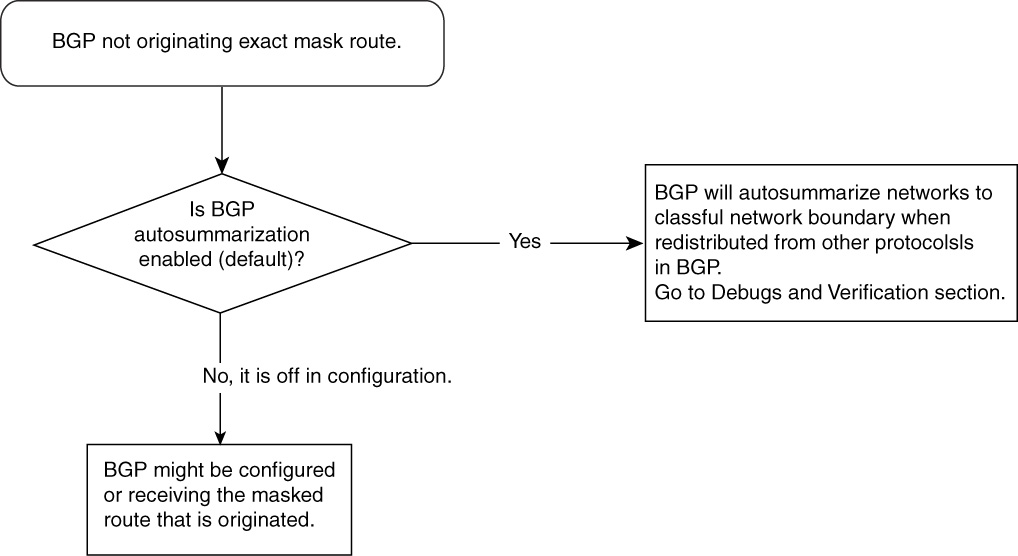
Figure 15-11 Problem-Resolution Flowchart
Debugs and Verification
Example 15-30 shows an example in which R1 has a static route for 100.100.100.0/24 and 131.108.5.0/24. Notice that these are subnetted Class A and B routes, respectively.
When these static routes are redistributed in BGP, BGP autosummarizes them to their natural class masks, which are /8 and /16 respectively.
Example 15-30 shows the relative configuration in R1 to redistribute these static routes in BGP; it also displays the BGP table output for these advertisements.
Example 15-30 Configuring Redistribution of Static Routes in BGP
R1# router bgp 109
no synchronization
redistribute static
neighbor 131.108.1.2 remote-as 109
ip route 100.100.100.0 255.255.255.0 Null0
ip route 131.108.5.0 255.255.255.0 Null0
R1#show ip bgp 100.100.100.0
BGP routing table entry for 100.0.0.0/8, version 2
Paths: (1 available, best #1, table Default-IP-Routing-Table)
Advertised to non peer-group peers:
131.108.1.2
Local
0.0.0.0 from 0.0.0.0 (1.1.1.1)
Origin incomplete, metric 0, localpref
100, weight 32768, valid, sourced, best
R1-2503#show ip bgp 131.108.5.0
BGP routing table entry for 131.108.0.0/16, version 3
Paths: (1 available, best #1, table Default-IP-Routing-Table)
Advertised to non peer-group peers:
131.108.1.2
Local
0.0.0.0 from 0.0.0.0 (1.1.1.1)
Origin incomplete, metric 0, localpref 100, weight 32768, valid, sourced, best
Note the mask in the output. /24 static routes are summarized to the network boundary of Class A and Class B, respectively.
Solution
IP prefixes need to be advertised with their original masks. One exception is when manual summarization is done. The problem of BGP advertising classful networks after redistribution can be overcome by disabling the autosummarization feature in BGP.
Example 15-31 shows the necessary configuration to achieve this; it also shows the BGP advertisement in the BGP table after this change.
Example 15-31 Disabling Autosummarization in BGP
R1# router bgp 109
no synchronization
redistribute static
no auto-summary
R1# show ip bgp 100.100.100.0
BGP routing table entry for 100.100.100.0/24, version 4
Paths: (1 available, best #1, table Default-IP-Routing-Table)
Flag: 0x208
Advertised to non peer-group peers:
131.108.1.2
Local
0.0.0.0 from 0.0.0.0 (1.1.1.1)
Origin incomplete, metric 0, localpref 100, weight 32768, valid, sourced, best
R1# show ip bgp 131.108.5.0
BGP routing table entry for 131.108.5.0/24, version 6
Paths: (1 available, best #1, table Default-IP-Routing-Table)
Flag: 0x208
Advertised to non peer-group peers:
131.108.1.2
Local
0.0.0.0 from 0.0.0.0 (1.1.1.1)
Origin incomplete, metric 0, localpref 100, weight 32768, valid, sourced, best
Note the masks in the output—they are exactly what there were configured originally.
In most cases, it would be desirable to turn off autosummarization so that proper mask routes can be advertised to BGP neighbors. Autosummarization plays a role only when any other protocol routes are redistributed into BGP. Because it is not common practice to redistribute other protocols into BGP, the autosummarization feature is not used much.
Problem in Propagating/Originating BGP Route to IBGP/EBGP Neighbors—Cause: Misconfigured Filters
A scenario might arise in which the BGP configuration to originate and propagate routes looks good, but BGP neighbors are not receiving the routes. The originator’s BGP table shows all the routes. There is a possibility that configured filters are the cause of the problem.
When implementing BGP in Cisco IOS Software, operators have many options to configure filters to control which routes to propagate to which neighbors. These filters could be fairly straightforward or could get very complex. Minor errors can result in undesirable route denial or advertisement to BGP speakers.
Figure 15-12 shows the flowchart to follow to fix this problem.
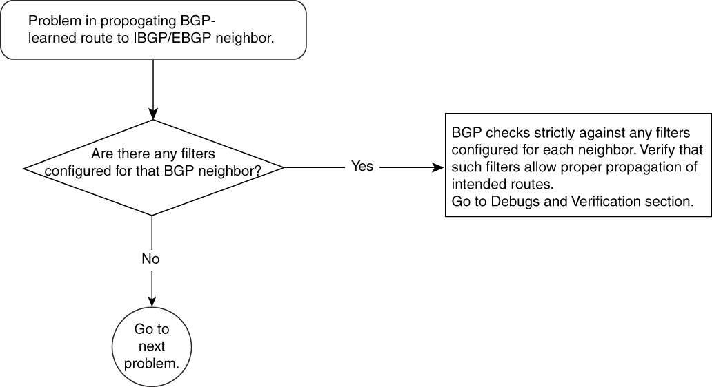
Figure 15-12 Problem-Resolution Flowchart
Debugs and Verification
Chapter 14 discusses using filters in BGP. Discussing every single filter is outside the scope of this book; however, some of most commonly seen real-world filtering mistakes and misconceptions are discussed.
Using a distribute list allows for standard access lists (1 to 99) and extended access lists (100 to 199). Example 15-32 gives a sample configuration of both.
Example 15-32 Sample Distribute List Configuration Using Standard and Extended Access Lists
R1# access-list 1 permit 100.100.100.0
router bgp 109
no synchronization
neighbor 131.108.1.2 remote-as 109
neighbor 131.108.1.2 distribute-list 1 out
R1# access-list 101 permit ip host 100.100.100.0 host 255.255.255.0
router bgp 109
no synchronization
neighbor 131.108.1.2 remote-as 109
neighbor 131.108.1.2 distribute-list 101 out
One common mistake that operators make is not realizing that there is an implicit deny at the end of each access list. All networks are denied except for those that are explicitly permitted in the access list. Also, standard and extended access lists are treated differently when it comes to BGP filters. In standard access lists, the mask portion is not checked and only the prefix portion is checked. For example, in the following access list, 100.100.100.0 could have any mask—/24, /26, and so on:
access-list 1 permit 100.100.100.0
In the following access list, on the other hand, the mask of 100.100.100.0 must be /24 and nothing else:
access-list 101 permit ip host 100.100.100.0 host 255.255.255.0
Similarly, when other methods are applied to filter BGP updates—namely, filter lists, prefix lists, route maps, distribute lists, and so on—care must be taken to understand the behavior of each method.
It is beyond the scope of this book to go over each filtering method that Cisco offers, but refer to the section, “Troubleshooting BGP Filtering.”
Solution
As discussed in Chapter 14, there are several other ways to filter BGP updates, and care must be taken in terms of what exactly is configured. Each kind of filter offers the power to control the BGP advertisement, but improper or incorrect use can result in incorrect or incomplete advertisements.
Problem in Propagating BGP Route to IBGP Neighbor but Not to EBGP Neighbor—Cause: BGP Route Was from Another IBGP Speaker
In some cases, certain routes are not propagated to IBGP neighbors but are propagated only to EBGP neighbors.
When IBGP speakers in an AS are not fully meshed and have no route reflector or confederation configuration, any route that is learned from an IBGP neighbor will not be given to any other IBGP neighbor. Such routes are advertised only to EBGP neighbors, as illustrated in Figure 15-13. Chapter 14 explains using route reflectors and confederations. You also can find information on this topic in the “Troubleshooting BGP When Route Reflectors Are Used” section, later in this chapter.

Figure 15-13 IBGP Network in Which IBGP Routes Are Not Propagated to Other IBGP Speakers
Figure 15-14 shows the flowchart to follow to fix this problem.
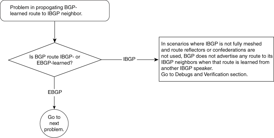
Figure 15-14 Problem-Resolution Flowchart
Debugs and Verification
Example 15-33 shows the necessary configuration to have an IBGP relationship between R8 to R1 and R1 to R2. This example also shows a sample configuration of R8 advertising 100.100.100.0/24 to R1.
Example 15-33 Configuring an IBGP Relationship Between R8/R1 and R1/R2
R8#
router bgp 109
no synchronization
network 100.100.100.0 mask 255.255.255.0
neighbor 206.56.89.2 remote-as 109
ip route 100.100.100.0 255.255.255.0 Null0
R1#
router bgp 109
no synchronization
neighbor 131.108.1.2 remote-as 109
neighbor 206.56.89.1 remote-as 109
R2#
router bgp 109
no synchronization
neighbor 131.108.1.1 remote-as 109
Example 15-33 shows that the IBGP network is not fully meshed and that the IBGP-learned route will not be given to any other IBGP neighbor.
Example 15-34 shows BGP table output from R8, R1, and R2, respectively. R8 is advertising 100.100.100.0/24, which shows up in its BGP table and in R1’s table. In the output of R1, notice the highlighted output “Not advertised to any peer.” Although R1 and R2 are IBGP neighbors, R1 does not advertise 100.100.100.0/24 to R2 and it is learned from another IBGP neighbor, R8.
Example 15-34 R8, R1, and R2 BGP Tables Show That an IBGP-Learned Route in R1 Will Not Be Given to IBGP Neighbor R2
R8#show ip bgp 100.100.100.0
BGP routing table entry for 100.100.100.0/24, version 3
Paths: (1 available, best #1, table Default-IP-Routing-Table)
Advertised to non peer-group peers:
206.56.89.2
Local
0.0.0.0 from 0.0.0.0 (8.8.8.8)
Origin IGP,metric 0,localpref 100,weight 32768,valid,sourced,local,best
R1#show ip bgp 100.100.100.0
BGP routing table entry for 100.100.100.0/24, version 9
Paths: (1 available, best #1, table Default-IP-Routing-Table)
Not advertised to any peer
Local
206.56.89.1 from 206.56.89.1 (8.8.8.8)
Origin IGP, metric 0, localpref 100, valid, internal, best
R1#show ip bgp summary
BGP router identifier 1.1.1.1, local AS number 109
BGP table version is 11, main routing table version 11
1 network entries and 1 paths using 133 bytes of memory
1 BGP path attribute entries using 52 bytes of memory
0 BGP route-map cache entries using 0 bytes of memory
0 BGP filter-list cache entries using 0 bytes of memory
BGP activity 24/237 prefixes, 35/34 paths, scan interval 15 secs
Neighbor V AS MsgRcvd MsgSent TblVer InQ OutQ Up/Down State/PfxRcd
131.108.1.2 4 109 4304 4319 11 0 0 1d20h 0
206.56.89.1 4 109 108 110 11 0 0 01:44:16 1
R2#show ip bgp 100.100.100.0
% Network not in table
In the output of R1, “Not advertised to any peer” means that even though R2 is the neighbor, it is an IBGP neighbor and 100.100.100.0/24 will not be advertised. This rule comes from RFC 1771 section 9.2.1, titled “Internal Updates”:
When a BGP speaker receives an UPDATE message from another BGP speaker located in its own autonomous system, the receiving BGP speaker shall not re-distribute the routing information contained in that UPDATE message to other BGP speakers located in its own autonomous system.
Solution
It is essential that IBGP-learned routes are propagated to other BGP speakers. BGP operators can use three methods to address this problem:
• Use IBGP full mesh.
• Design a route-reflector model.
• Design a confederation model.
IBGP Full Mesh
Having an IBGP full mesh is unacceptable even in a small ISP network.
For larger ISPs that maintain several hundred BGP speakers, IBGP full mesh would harm them more than providing benefit. Therefore, savvy BGP operators typically do not choose this method. Chapter 14 explains this is greater detail.
Designing a Route-Reflector Model
RFC 1966 discusses a model to avoid IBGP full mesh by introducing the concept of route-reflector servers and route-reflector clients.
Servers peer BGP with all clients in the cluster. A cluster is a set of servers and clients. Clients peer BGP only with servers. Clients advertise BGP updates to servers, and servers then reflect them to other clients. In Figure 15-15, R1 act as the server and R8 and R2 act as clients. R1, R2, and R8 form a cluster. Refer to Chapter 14 to undersatnd Route-Reflection in detail.

Figure 15-15 Route-Reflector Model to Avoid Full-Mesh IBGP
Example 15-35 shows the relevant configuration to make R1 the route-reflector. Route-reflector clients need no additional configuration other than what is already shown in Example 15-33.
Example 15-35 Configuring R1 as the Route Reflector and R2 and R8 as Route-Reflector Clients
R1# router bgp 109
no synchronization
neighbor 131.108.1.2 remote-as 109
neighbor 131.108.1.2 route-reflector-client
neighbor 206.56.89.1 remote-as 109
neighbor 206.56.89.1 route-reflector-client
The output in Example 15-36 shows that R1 receives 100.100.100.0/24 from R8 and advertises to R2 (131.108.1.2). Notice that this was not the case in the original problem in Figure 15-13. Example 15-36 also shows that R2 receives 100.100.100.0/24 from R1.
Example 15-36 BGP Table Output to Display How Route Reflectors Solved the IBGP Update Failure Problem
R1#show ip bgp 100.100.100.0
BGP routing table entry for 100.100.100.0/24, version 13
Paths: (1 available, best #1, table Default-IP-Routing-Table)
Flag: 0x208
Advertised to non peer-group peers:
131.108.1.2
Local, (Received from a RR-client)
206.56.89.1 from 206.56.89.1 (8.8.8.8)
Origin IGP, metric 0, localpref 100, valid, internal, best
R2#show ip bgp 100.100.100.0
BGP routing table entry for 100.100.100.0/24, version 35
Paths: (1 available, best #1, table Default-IP-Routing-Table)
Flag: 0x208
Not advertised to any peer
Local
206.56.89.1 from 131.108.1.1 (8.8.8.8)
Origin IGP, metric 0, localpref 100, valid, internal, best
Originator: 8.8.8.8, Cluster list: 1.1.1.1
The highlighted section in R1’s output shows that it is advertising 100.100.100.0/24 to R2, its IBGP neighbor, which was not the case in Example 15-34.
Designing a Confederation Model
RFC 1965 explains how an AS confederation for BGP can avoid full IBGP mesh. With confederations, the BGP network is divided into small sub–autonomous systems. These sub–autonomous systems are connected to other sub–autonomous systems. These sub–autonomous systems need not be fully meshed. BGP speakers within a sub–autonomous system must have a full mesh of IBGP. If the number of sub–autonomous systems grows to a large number of IBGP speakers, sub–autonomous system IBGP speakers use route reflectors. All routers take a configuration change when moved from an IBGP model to a confederation model. Refer to Chapter 14 to understand Confederation in detail.
Figure 15-16 shows that R1 and R2 are combined in a sub-AS and that R8 is in its own sub-AS.

Figure 15-16 Confederation Model
Example 15-37 highlights all the changes in the configuration of Routers R1, R2, and R8.
Example 15-37 Configuring the Network of R1, R2, and R8 as a Confederation Model
R8#
router bgp 65201
bgp confederation identifier 109
bgp confederation peers 65200 65201
network 100.100.100.0 mask 255.255.255.0
neighbor 206.56.89.2 remote-as 65200
ip route 100.100.100.0 255.255.255.0 Null0
R1# router bgp 65200
bgp confederation identifier 109
bgp confederation peers 65201 65200
neighbor 131.108.1.2 remote-as 65200
neighbor 206.56.89.1 remote-as 65201
R2# router bgp 65200
no synchronization
bgp confederation identifier 109
bgp confederation peers 65200 65201
neighbor 131.108.1.1 remote-as 65200
Example 15-37 shows a significant change in BGP configuration of Routers R1, R2, and R8. When a BGP network migrates to a confederation, all routers need configuration changes. In Example 15-37, confederation identifier represents that real AS of the network; the confederation peers command lists the peering confederation sub-AS in the BGP network. The confederation sub-AS is configured with the router bgp command. All BGP updates sent to other confederations are sent with a confederation sub-AS list similar to the AS_PATH list, but updates to EBGP neighbors are sent with the real AS number. A prefix received from the outside confederation sub-AS is advertised to all confederation neighbors, internal or external, resulting in prefix propagation—this was not possible in partially meshed IBGP. To the outside world, a confederation has no value because it is a technique used locally in the BGP network to reduce an IBGP mesh.
Example 15-38 shows the output of the BGP table from each router.
Example 15-38 BGP Tables from the Routers in a BGP Confederation
R8#show ip bgp 100.100.100.0
BGP routing table entry for 100.100.100.0/24, version 2
Paths: (1 available, best #1, table Default-IP-Routing-Table)
Advertised to non peer-group peers:
206.56.89.2
Local
0.0.0.0 from 0.0.0.0 (8.8.8.8)
Origin IGP, metric 0, localpref 100, weight 32768, valid, sourced, local,best
R1#show ip bgp 100.100.100.0
BGP routing table entry for 100.100.100.0/24, version 2
Paths: (1 available, best #1, table Default-IP-Routing-Table)
Advertised to non peer-group peers:
131.108.1.2
(65201)
206.56.89.1 from 206.56.89.1 (8.8.8.8)
Origin IGP, metric 0, localpref 100, valid, confed-external, best
R2#show ip bgp 100.100.100.0
BGP routing table entry for 100.100.100.0/24, version 2
Paths: (1 available, best #1, table Default-IP-Routing-Table)
Flag: 0x208
Not advertised to any peer
(65201)
206.56.89.1 from 131.108.1.1 (1.1.1.1)
Origin IGP, metric 0, localpref 100, valid, internal, best
R8 is advertising 100.100.100.0/24 to R1. In R1’s output, the highlighted line shows the confederation sub-AS, 65201, that 100.100.100.0/24 update has traversed. This is the sub-AS that has R8 in it. R1 advertises this update to R2 because this update came from another confederation sub-AS. This setup sidesteps the need for a full mesh of R1, R2, and R8, which otherwise was needed to propagate 100.100.100.0/24 from R8 to R2.
Problem in Propagating IBGP Route to IBGP/EBGP Neighbor—Cause: IBGP Route Was Not Synchronized
A scenario might arise in which an IBGP learned route is not propagated to any BGP neighbor, whether IBGP or EBGP. One case could be that when an IBGP-learned route is not synchronized, that route is not considered as a candidate to advertise to other BGP neighbors. As you remember from previous discussions in Chapter 14, a BGP route is synchronized only if it has been learned through an IGP or a static route first.
In Cisco IOS Software, BGP advertises only what it considers the best path to its neighbors. If an IBGP path is not synchronized, it is not included in the best path calculation.
Figure 15-17 shows the flowchart to follow to fix this problem.

Figure 15-17 Problem-Resolution Flowchart
Debugs and Verification
Refer back to Chapter 14 for details about the rules for synchronization.
Example 15-39 shows how an unsynchronized route would appear in BGP table.
Example 15-39 BGP Table with Unsynchronized Route
R2#show ip bgp 100.100.100.0
BGP routing table entry for 100.100.100.0/24, version 3
Paths: (1 available, no best path)
Flag: 0x208
Not advertised to any peer
(65201)
206.56.89.1 from 131.108.1.1 (1.1.1.1)
Origin IGP, metric 0, localpref 100, valid, internal, not synchronized
The highlighted output in Example 15-39 shows that R2 did not consider 100.100.100.0/24 as synchronized and failed to install it in the routing table; therefore, it did not advertise the route to any peer.
Solution
As discussed in Chapter 14, either turn off synchronization or make the routes synchronized by redistributing them in the IGP at the router that first introduced this route in IBGP domain. The following selection has an example to accomplish this.
Troubleshooting BGP Route Not Installing in Routing Table
This section discusses issues related to BGP routes not getting installed in the IP routing table. If a router must forward an IP packet by looking at the IP destination address in IP packet, the router must have an IP routing table entry for the subnet of the IP destination address.
If the BGP process fails to create an IP routing table entry, all traffic destined for missing IP subnets in the routing table will be dropped. This is a generic behavior of hop-by-hop IP packet forwarding done by routers.
Problems in this section assume that the BGP table has all the updates for IP prefixes but that BGP is not installing them in IP routing table.
Following is the list of all problems discussed in this section:
• An IBGP-learned route is not getting installed in the IP routing table.
• An EBGP-learned route is not getting installed in the IP routing table.
Problem: IBGP-Learned Route Not Getting Installed in IP Routing Table
The most common causes of this problem are as follows:
• IBGP routes are not synchronized.
• The BGP next hop is not reachable.
The sections that follow discuss these causes and how to resolve the problem based on the cause.
IBGP-Learned Route Not Getting Installed in IP Routing Table—Cause: IBGP Routes Are Not Synchronized
IBGP will not install or propagate a route to other BGP speakers unless IBGP-learned routes are synchronized. Synchronization means that for an IBGP-learned route, there must exist an identical route in the IP routing table provided by an IGP (OSPF, IS-IS, and so on).
This means that the IGP must hold all external BGP routing information. This can be accomplished by redistributing EBGP into an IGP at the border routers of an AS.
In Figure 15-18, R1 is originating 100.100.100.0/24 to its IBGP neighbor, R2 (13.108.10.2). R2 is configured to form IBGP neighbors with R1 and is originating nothing.

Figure 15-18 R1 Advertising 100.100.100.0/24 to IBGP Neighbor R2, Which Checks for Synchronization of BGP Routes
Figure 15-19 shows the flowchart to follow to resolve this problem.
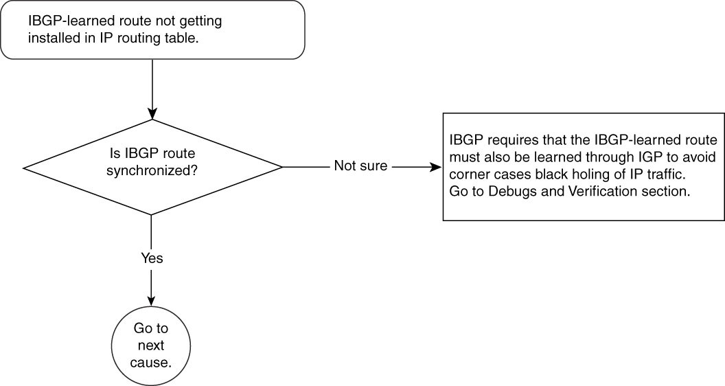
Figure 15-19 Problem-Resolution Flowchart
Debugs and Verification
Example 15-40 is the relevant BGP configuration needed in R1 and R2 to originate and receive 100.100.100.0/24 through IBGP.
Example 15-40 Configuring R1 and R2 to Originate and Receive 100.100.100.0/24 Through IBGP
R1# router bgp 109
network 100.100.100.0 mask 255.255.255.0
neighbor 131.108.10.2 remote-as 109
neighbor 131.108.10.2 update-source Loopback0
ip route 100.100.100.0 255.255.255.0 Null0
R2# router bgp 109
neighbor 131.108.10.1 remote-as 109
neighbor 131.108.10.1 update-source Loopback0
Example 15-41 shows that R2 has received an IBGP update for 100.100.100.0/24.
Example 15-41 R2’s BGP Routing Table Entry Indicates That an IBGP Update Was Received for 100.100.100.0/24
R2#show ip bgp 100.100.100.0
BGP routing table entry for 100.100.100.0/24, version 3
Paths: (1 available, no best path)
Flag: 0x208
Not advertised to any peer
Local
131.108.10.1 from 131.108.10.1 (131.108.10.1)
Origin IGP, metric 0, localpref 100, valid, internal, not synchronized
R2#show ip route 100.100.100.0
% Network not in table
The output in Example 15-41 also explains that BGP finds no best-path candidate to be installed in IP routing table. The reason is that this particular BGP update is not synchronized.
Solution
A network operator can choose to work around this problem in two ways:
• Synchronize all BGP routes.
• Turn off synchronization.
Synchronizing All IBGP Routes
The solution of turning off synchronization needs no further explanation. Synchronizing all BGP routes, however, requires some more detailed coverage.
To synchronize 100.100.100.0/24, R1 must advertise this route in its IGP so that R2 can receive it through both IBGP and IGP. Example 15-42 shows that R1 is advertising this route by redistributing static routes in OSPF, and R2 receives it as an external OSPF route and in normal IBGP as well.
Example 15-42 Configuration Needed to Advertise All Routes Advertised Through IBGP and IGP (OSPF)
R1# router ospf 1
redistribute static subnets
network 131.108.1.0 0.0.0.255 area 0
R1# router bgp 109
network 100.100.100.0 mask 255.255.255.0
neighbor 131.108.10.2 remote-as 109
neighbor 131.108.10.2 update-source Loopback0
ip route 100.100.100.0 255.255.255.0 Null0
The configuration in Example 15-42 shows that OSPF is redistributing static routes; the only static route shown is 100.100.100.0/24. BGP is also advertising the same prefix to R2, as demonstrated in Example 15-43.
Example 15-43 Output to Show R2 Is Receiving a Synchronized IBGP Route from R1
R2#show ip route 100.100.100.0
Routing entry for 100.100.100.0/24
Known via "ospf 1", distance 110, metric 20, type extern 2, forward metric 10
Redistributing via ospf 1
Last update from 131.108.1.1 on Ethernet0, 00:07:21 ago
Routing Descriptor Blocks:
* 131.108.1.1, from 131.108.10.1, 00:07:21 ago, via Ethernet0
Route metric is 20, traffic share count is 1
R2#show ip bgp 100.100.100.0
BGP routing table entry for 100.100.100.0/24, version 4
Paths: (1 available, best #1, table Default-IP-Routing-Table)
Flag: 0x208
Not advertised to any peer
Local
131.108.10.1 from 131.108.10.1 (131.108.10.1)
Origin IGP, metric 0, localpref 100, valid, internal, synchronized, best
In Example 15-43, BGP now marks this route as synchronized and will install this route in its IP routing table. It also will propagate this route to other BGP speakers. In Example 15-43, the routing table chooses the OSPF route instead of the IBGP route because of the lower administrative distance of 110 over 200.
Note
In the case of OSPF, Cisco IOS Software expects the OSPF router ID (RID) and the BGP RID for R1, the advertising router, to be identical for synchronization to work properly. There is no such restriction for any other IGPs.
Turning Off Synchronization
This method is widely used in almost all BGP networks.
Example 15-44 provides the necessary configuration to accomplish this.
Example 15-44 Turning Off Synchronization
R2#
router bgp 109
no synchronization
As seen in the previous section, all routes in BGP must also be redistributed in IGP to have synchronization in the IBGP network.
With the size of BGP tables these days (more than 110,000 entries), it is not recommended that you redistribute all BGP routes into an IGP. Therefore, it becomes common practice to turn off synchronization instead.
IBGP-Learned Route Not Getting Installed in IP Routing Table—Cause: IBGP Next Hop Not Reachable
The cause of this problem is most common in IBGP-learned routes where BGP next-hop address should have been learned through an Interior Gateway Protocol (IGP). Failure to reach the next hop is an IGP problem, and BGP is merely a victim. With BGP, when IP prefixes are advertised to an IBGP neighbor, the NEXT-HOP attribute of the prefix does not change. The IBGP receiver must have an IP route to reach this next hop.
Figure 15-20 shows the flowchart to follow to resolve this problem.

Figure 15-20 Problem-Resolution Flowchart
Figure 15-21 shows that NEXT-HOP of BGP routes advertised to IBGP neighbors are not changed and might result in route installation failure.
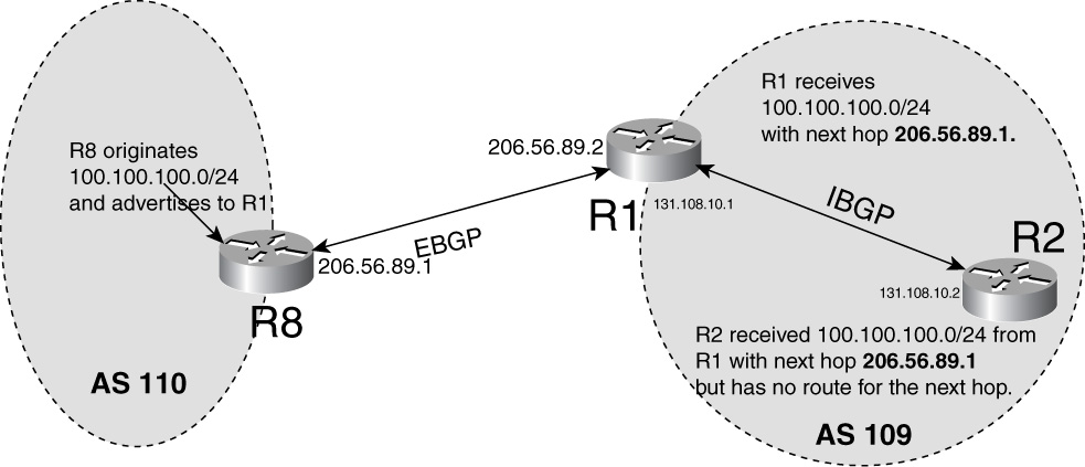
Figure 15-21 Next hop of BGP Routes Advertised to IBGP Neighbors Is Not Changed and Might Result in Route Installation Failure
Debugs and Verification
Example 15-45 shows that R8 is advertising the 100.100.100.0/24 route to its EBGP peer R1, which will advertise this route to R2. However, on R2, the problem of the next hop appears.
Example 15-45 shows the relevant configuration of R8, R1, and R2.
Example 15-45 Configuration Needed in R1, R2, and R8 to Form Neighbor Relationship and Originate and Propagate 100.100.100.0/24
R8# router bgp 110
no synchronization
network 100.100.100.0 mask 255.255.255.0
neighbor 206.56.89.2 remote-as 109
ip route 100.100.100.0 255.255.255.0 Null0
R1# router bgp 109
no synchronization
neighbor 131.108.10.2 remote-as 109
neighbor 131.108.10.2 update-source Loopback0
neighbor 206.56.89.1 remote-as 110
R2# router bgp 109
no synchronization
neighbor 131.108.10.1 remote-as 109
neighbor 131.108.10.1 update-source Loopback0
The configuration in Example 15-45 shows that R8 has one EBGP neighbor, R1, which has R8 and R2 as EBGP and IBGP neighbors, respectively. R2 has R1 as an IBGP neighbor.
R8 is advertising 100.100.100.0/24 to R1, and R1 will propagate that to R2 as an IBGP advertisement.
Example 15-46 shows that R1 receives this route, installs it in its routing table, and propagates it to R2 131.108.10.2.
Example 15-46 R1 Receives the Route and Propagates It to R2
R1#show ip bgp 100.100.100.0
BGP routing table entry for 100.100.100.0/24, version 2
Paths: (1 available, best #1, table Default-IP-Routing-Table)
Advertised to non peer-group peers:
131.108.10.2
110
206.56.89.1 from 206.56.89.1 (100.100.100.8)
Origin IGP, metric 0, localpref 100, valid, external, best
R1#show ip route 100.100.100.0
Routing entry for 100.100.100.0/24
Known via "bgp 109", distance 20, metric 0
Tag 110, type external
Last update from 206.56.89.1 00:04:50 ago
Routing Descriptor Blocks:
* 206.56.89.1, from 206.56.89.1, 00:04:50 ago
Route metric is 0, traffic share count is 1
AS Hops 1
The highlighted output shows that R1 is advertising 100.100.100.0/24 to 131.108.10.2, which is R2.
In Figure 15-21, R2 is an IBGP peer of R1, which advertises 100.100.100.0 /24 to R2. Then R2 receives this BGP route with a Next-hop of 206.56.89.1 but fails to install 100.100.100.0/24 in its routing table, as demonstrated in Example 15-47.
Example 15-47 R2 Fails to Install the 100.100.100.0 /24 Route in Its Routing Table
R2#show ip bgp 100.100.100.0
BGP routing table entry for 100.100.100.0/24, version 0
Paths: (1 available, no best path)
Not advertised to any peer
110
206.56.89.1 (inaccessible) from 131.108.10.1 (131.108.10.1)
Origin IGP, metric 0, localpref 100, valid, internal
R2#show ip route 100.100.100.0
% Network not in table
Notice that 206.56.89.1 is inaccessible because R2 does not have a route to reach it in its IP routing table, as confirmed by Example 15-48.
Example 15-48 R2’s IP Routing Table Confirms an Inaccessible Route
R2#show ip route 206.56.89.1
% Network not in table
This might be because R1 is not advertising 206.56.89.1 to R2 through its IGP (OSPF) or R2 is not installing 206.56.89.1 for any other reason.
Solution
BGP requires the next hop of any BGP route to resolve to a physical interface. This might or might not require multiple recursive lookups in the IP routing table. Two common solutions exist for addressing this problem:
• Announce the EBGP next hop through an IGP using a static route or redistribution.
• Change the next hop to an internal peering address.
Announce the EBGP Next Hop Through an IGP Using a Static Route or Redistribution
This solution simply requires that the subnet 206.56.89.0/30 be advertised by R1 in its IGP—OSPF, in this example.
Example 15-49 shows the necessary configuration in R1 to accomplish this and shows R2 receiving this route through an IGP.
Example 15-49 Configuring R1 to Advertise EBGP Next Hop Through OSPF
R1# router ospf 1
network 206.56.89.0 0.0.0.7 area 0
The output in Example 15-50 shows that R2 receives this route through OSPF.
Example 15-50 R2’s IP Route Table Confirms Receipt of the EBGP Next-Hop Route Advertisement Through OSPF
R2# show ip route 206.56.89.0 255.255.255.252
Routing entry for 206.56.89.0/30
Known via "ospf 1", distance 110, metric 74, type intra area
Redistributing via ospf 1
Last update from 131.108.1.1 on Ethernet0, 00:03:17 ago
Routing Descriptor Blocks:
* 131.108.1.1, from 1.1.1.1, 00:03:17 ago, via Ethernet0
Route metric is 74, traffic share count is 1
Note that 131.108.1.1 resolves to interface Ethernet0.
Change the Next Hop to an Internal Peering Address
This solution suggests that R1 change the BGP next hop to its loopback address when advertising IBGP routes to R2.
Example 15-51 shows that the configuration in R1 requires the BGP next hop to be changed to its own loopback address.
Example 15-51 Configuring R1 So That the BGP Next Hop Is Its Own Loopback Address
R1# router bgp 109
neighbor 131.108.10.2 remote-as 109
neighbor 131.108.10.2 update-source Loopback0
neighbor 131.108.10.2 next-hop-self
neighbor 206.56.89.1 remote-as 110
The command neighbor 131.108.10.2 next-hop-self changes the Next-hop to its own loop-back 0 (131.108.10.1). The neighbor-131.108.10.2 update-source loopback 0 command makes R1’s loopback 0 the source of all BGP packets sent to R2.
Example 15-52 shows this change reflected in R2.
Example 15-52 R2’s BGP Route Table Confirms That R1’s Loopback Address Is the Next Hop of All BGP Updates Sent to R2
R2#show ip bgp 100.100.100.0
BGP routing table entry for 100.100.100.0/24, version 2
Paths: (1 available, best #1, table Default-IP-Routing-Table)
Not advertised to any peer
110
131.108.10.1 from 131.108.10.1 (131.108.10.1)
Origin IGP, metric 0, localpref 100, valid, internal, best
R2#show ip route 100.100.100.0
Routing entry for 100.100.100.0/24
Known via "bgp 109", distance 200, metric 0
Tag 110, type internal
Last update from 131.108.10.1 00:00:25 ago
Routing Descriptor Blocks:
* 131.108.10.1, from 131.108.10.1, 00:00:25 ago
Route metric is 0, traffic share count is 1
AS Hops 1
The exterior Next-Hop changed to the loopback of R1, 131.108.10.1.
This solution is more widely used and is the preferred method of announcing the next hop to IBGP peer. In the simple example of Figure 15-21, the solution of changing the next hop to an internal peering address allows one less IP subnet to go in the IP routing table. In addition, it helps in troubleshooting because network operators recall their internal loopback addresses quicker than external IP subnets, such as that used in the EBGP connection.
Problem: EBGP-Learned Route Not Getting Installed in IP Routing Table
Just as with IBGP, EBGP routes might not get installed in the IP routing table, resulting in a lack of IP traffic reachability to those routes. Multiple causes of this problem might exist, depending on which EBGP scenario is being looked at.
The most common causes of EBGP routes not getting installed are as follows:
• The BGP next hop is not reachable in case of multihop EBGP.
• The multiexit discriminator (MED) value is infinite.
The sections that follow discuss these causes and how to resolve the problem based on the cause.
EBGP-Learned Route Not Getting Installed in IP Routing Table—Cause: BGP Routes Are Dampened
Dampening is the way to minimize instability in a local BGP network caused by unstable BGP routes from EBGP neighbors. RFC 2439, “BGP Route Flap Damping,” describes in detail how dampening works. In short, dampening is the way to assign a penalty for a flapping BGP route. A withdrawal of a prefix is considered a flap. A penalty of 1000 is assigned for each flap; if the flap penalty reaches the suppress limit because of continued flaps (default 2000), the BGP path is suppressed and is taken out of the routing table. This penalty is decayed exponentially based on the half-life time (default 15 minutes). When the penalty reaches the reuse value (default 750), the path is unsuppressed and is installed in the routing table and advertised to other BGP neighbors. Any dampened path can be suppressed only until the max suppress time (default 60 minutes). Dampening is applied only to EBGP neighbors, not to IBGP neighbors.
BGP dampening is off by default; the following BGP command turns on dampening:
router bgp 109
bgp dampening
Cisco IOS Software allows dampening parameters to be changed and are defined as follows:
router bgp 1009
bgp dampening half-life-time reuse suppress maximum-suppress-time
Here, the value range for the options is as follows:
• half-life-time—Range is 1 to 45 minutes. Current default is 15 minutes.
• reuse—Range is 1 to 20,000. Default is 750.
• suppress—Range is 1 to 20,000. Default is 2000.
• max-suppress-time—Maximum duration that a route can be suppressed. Range is 1 to 255. Default is four times half-life-time.
Figure 15-22 shows the flowchart to follow to resolve this problem.

Figure 15-22 Problem-Resolution Flowchart
Debugs and Verification
Figure 15-23 shows a simple EBGP setup between R1 and R2 in AS 109 and AS 110, respectively. R2 has advertised 100.100.100.0/24 to R1. To show how dampening works, R2 is made to flap 100.100.100.0/24 multiple times. Removing the route in R2’s routing table and putting it back can simulate flapping. R1 receives these flaps and, if configured with dampening, assigns penalties per flap.
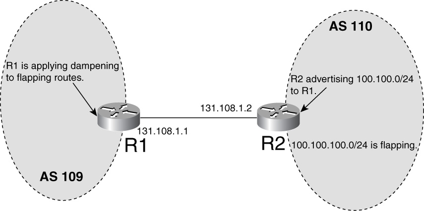
Figure 15-23 EBGP Setup to Demonstrate Route Dampening
Example 15-53 shows the necessary debugs run to observe the dampening feature in R1 running Cisco IOS Software.
Example 15-53 Observing the BGP Dampening Feature
R1#debug ip bgp dampening 1
R1#debug ip bgp updates 1
access-list 1 permit 100.100.100.0 0.0.0.0
Most of the BGP debugs can be run along with an access list to limit the output created by these debugs. Access list 1 is permitting only 100.100.100.0.
Example 15-54 shows the debug output and flap statistics in BGP output.
Example 15-54 Debugs to Verify Dampening of 100.100.100.0/24
Dec 13 03:33:57.966 MST: BGP(0): 131.108.1.2 rcv UPDATE about 100.100.100.0/24 --
withdrawn
Dec 13 03:33:57.966 MST: BGP(0): charge penalty for 100.100.100.0/24 path 110 with
halflife-time 15 reuse/suppress 750/2000
Dec 13 03:33:57.966 MST: BGP(0): flapped 4 times since 00:02:58. New penalty is 3838
R1#show ip bgp 100.100.100.0
BGP routing table entry for 100.100.100.0/24, version 17
Paths: (1 available, no best path)
Flag: 0x208
Not advertised to any peer
110, (suppressed due to dampening)
131.108.1.2 from 131.108.1.2 (10.0.0.3)
Origin IGP, metric 0, localpref 100, valid, external
Dampinfo: penalty 3793, flapped 4 times in 00:03:13, reuse in 00:35:00
Highlighted debug and show command output shows that 100.100.100.0/24 has flapped four times in 3 minutes and 13 seconds. For each flap, a penalty of 1000 is assigned; because the suppress limit of 2000 has been exceeded, 100.100.100.0/24 is suppressed and removed from the routing table.
Solution
If R1 wants to reinstall 100.100.100.0/24, it can do the following:
1 Wait for the penalty to go below the reuse limit (750).
2 Remove dampening altogether from the BGP configuration.
3 Clear the flap statistics.
Example 15-55 shows how the dampened path can be cleared and immediately get installed in the routing table. debug ip bgp update 1 is on to display the activity in the BGP process.
Example 15-55 Clearing BGP Dampening Through a Command Line with Debugs On
R1#clear ip bgp dampening 100.100.100.0
Dec 13 03:36:56.205 MST: BGP(0): Revise route installing 100.100.100.0/24 ->
131.108.1.2 to main IP table
The output in Example 15-55 came from debug ip bgp update 1 running to display activity of 100.100.100.0/24 going into the IP routing table. Example 15-56 shows the final BGP routing table entries.
Example 15-56 BGP Routing Table Entries
R1#show ip bgp 100.100.100.0
BGP routing table entry for 100.100.100.0/24, version 18
Paths: (1 available, best #1, table Default-IP-Routing-Table)
Flag: 0x208
Not advertised to any peer
110
131.108.1.2 from 131.108.1.2 (10.0.0.3)
Origin IGP, metric 0, localpref 100, valid, external, best
R1#show ip route 100.100.100.0
Routing entry for 100.100.100.0/24
Known via "bgp 109", distance 20, metric 0
Tag 110, type external
Last update from 131.108.1.2 00:02:45 ago
Routing Descriptor Blocks:
* 131.108.1.2, from 131.108.1.2, 00:02:45 ago
Route metric is 0, traffic share count is 1
AS Hops 1, BGP network version 0
EBGP-Learned Route Not Getting Installed in IP Routing Table—Cause: BGP Next Hop Not Reachable in Case of Multihop EBGP
In a multihop EBGP session, EBGP speakers are not directly connected. Peering between loopback addresses of adjacent routers also is considered multihop.
This problem of an EBGP multihop route not getting installed in an IP routing table is identical to the IBGP next hop issue; however, most of the commonly seen problems occur when the router fails to resolve the next-hop address to an interface.
In this problem, the multihop EBGP next hop is reachable through a BGP route whose next hop is again the original multihop BGP next hop. For example, to reach prefix A, the next hop is prefix B; to reach prefix B, the next hop is again B. This is considered a recursion problem in which a router cannot resolve to an interface to reach the next hop B.
Figure 15-24 shows how R2 will not install routes from R1 whose next hop cannot be resolved to an interface.

Figure 15-24 R2 Fails to Install Routes from R1 Because of Next Hop/Interface Resolution
Figure 15-25 shows the flowchart to follow to resolve this problem.

Figure 15-25 Problem-Resolution Flowchart
Debugs and Verification
R1 and R2 are peering to each other’s Loopback addresses. R1 is advertising 100.100.100.0/24 to its multihop EBGP neighbor R2 with a next hop of 131.108.10.1.
R2 has a default route that it uses to form a BGP neighbor relationship with R1, but failure to resolve the next hop to an interface results in routes not getting installed in the routing table.
Example 15-49 shows that R2 is receiving 100.100.100.0/24 from R1 with the next hop of 131.108.10.1. However, this next hop is advertised by R1 to R2 only through BGP. Notice in the output of Example 15-57 that the next hop for BGP update of 131.108.10.1/32 is 131.108.10.1. R2 can never resolve the reachability for 131.108.10.1 through any physical interface. In Cisco IOS Software, BGP can detect this behavior and marks 100.100.100.0/24 as an unacceptable route to go in Best Path calculation and thus never go in the IP routing table.
Example 15-57 EBGP Multihop Will Not Be Capable of Resolving the Next Hop
R2#show ip bgp 100.100.100.0
BGP routing table entry for 100.100.100.0/24, version 2
Paths: (1 available, best #1, table Default-IP-Routing-Table)
Flag: 0x208
Not advertised to any peer
109
131.108.10.1 from 131.108.10.1 (131.108.10.1)
Origin IGP, metric 0, localpref 100, valid, external, best
R2#show ip bgp 131.108.10.1
BGP routing table entry for 131.108.10.1/32, version 5
Paths: (1 available, no best path)
Flag: 0x208
Not advertised to any peer
109
131.108.10.1 (inaccessible) from 131.108.10.1 (131.108.10.1)
Origin IGP, metric 0, localpref 100, valid, external
R2#show ip route 131.108.10.1
Routing entry for 131.108.10.1/32
Known via "bgp 110", distance 20, metric 0
Tag 109, type external
Last update from 131.108.10.1 00:00:38 ago
Routing Descriptor Blocks:
* 131.108.10.1, from 131.108.10.1,00:00:38 ago
Route metric is 0, traffic share count is 1
AS Hops 1
R2#show ip route 131.108.10.1
Routing entry for 131.108.10.1/32
Known via "bgp 110", distance 20, metric 0
Tag 109, type external
Last update from 131.108.10.1 00:00:38 ago
Routing Descriptor Blocks:
* 131.108.10.1, from 131.108.10.1,00:00:04 ago
Route metric is 0, traffic share count is 1
AS Hops 1
Note the time stamp in IP route output; it is resetting every minute.
This route in Example 15-57 will keep coming and going every minute as the Cisco IOS Software BGP scanner process detects such inconsistencies in the BGP next hop and removes that route.
Solution
The solution to this problem based on this cause is to simply have a more specific route for the next-hop address. In the case of EBGP, this is commonly done by having a static route for the multihop EBGP peering address.
This instance is observed in the case of multihop EBGP sessions when the next-hop address is not directly connected and the IP routing table must have an explicit route to the next-hop address.
The simple solution lies in creating a static route from R2 to reach the R1 loopback, which is the next hop of all prefixes advertised by R1 to R2. This can be done with the following command on R2:
ip route 131.108.10.1 255.255.255.255 131.108.1.1
The static route 131.108.10.1 is the loopback address of R1, and 131.108.1.1 is the physical interface address of R1.
EBGP-Learned Route Not Getting Installed in the Routing Table—Cause: Multiexit Discriminator (MED) Value Is Infinite
In Cisco IOS Software, if a multiexit discriminator (MED) is set to infinite 4294967295, the router will not install this route in the routing table.
Figure 15-26 shows the flowchart to follow to resolve this problem.

Figure 15-26 Problem-Resolution Flowchart
Debugs and Verification
In Cisco IOS Software, an infinite MED in a BGP update makes it incapable of entering the routing table. This rare occurrence is typically the result of misconfiguration.
Example 15-58 shows the output of the BGP table for prefix 100.100.100.0/24. Notice the metric value of 4.29 billion, which Cisco IOS Software considers as infinite. Example 15-58 also shows how R2 can be configured to set the MED value equal to 4.29 billion. The infinite metric sometimes is used in route servers, which provide a mirror view of the Internet BGP table. Setting the metric to infinity prohibits such routes from going in the IP routing table, so no IP traffic will use those routes. This case is discussed here just to show a corner case of a BGP path not getting installed in the routing table. Such a configuration is not seen in real BGP networks.
Example 15-58 BGP Route Table for Prefix 100.100.100.0/24 Indicates a Metric Set to Infinity
R2#show ip bgp 100.100.100.0
BGP routing table entry for 100.100.100.0/24, version 0
Paths: (1 available, no best path)
Not advertised to any peer
1
172.16.126.1 from 172.16.126.1 (172.16.1.1)
Origin IGP, metric 4294967295, localpref 100, valid, external
R2#show ip route 100.100.100.0
% Network not in table
R2# router bgp 2
no synchronization
neighbor 172.16.126.1 remote-as 1
neighbor 172.16.126.1 route-map SET_MED in
R2#show route-map SET_MED
route-map SET_MED, permit, sequence 10
Match clauses:
Set clauses:
metric 4294967295
Policy routing matches: 0 packets, 0 bytes
Troubleshooting BGP Route-Reflection Issues
Route reflectors (RR), discussed in RFCs 1966 and 2796, are used to avoid IBGP full mesh in an AS, as required by RFC 1771. Route reflection ensures that all IBGP speakers in an AS receive BGP updates from all parts of the network without having to run IBGP between all the routers in the network. Route reflection reduces the number of required IBGP connections and also offers faster convergence in an IBGP network when compared with a full-mesh IBGP network.
Route-reflector clients (RRCs) typically peer IBGP with one or more RR, and they can have EBGP connections unconditionally. Logical BGP connections between RR and RRC typically follow the physical connection topology. These are some of the common rules that help BGP operators troubleshoot BGP route-reflector issues.
This section discusses various issues seen in BGP networks related to route reflection. The most common problems in route-reflection networks are as follows:
• An extra BGP updated stored by a route-reflector client
• Convergence time improvement for route reflectors and clients
• Loss of redundancy between route reflectors and route-reflector clients
Problem: Configuration Mistakes—Cause: Failed to Configure IBGP Neighbor as a Route-Reflector Client
Configuring route reflectors is fairly simple. In route-reflector BGP configuration, IBGP neighbors’ peering addresses are listed as route-reflector clients; however, a BGP operator inadvertently might configure an incorrect IBGP peering address as a route-reflector client.
Figure 15-27 shows that R1 is an RR. R8 and R2 are RRCs of R1.
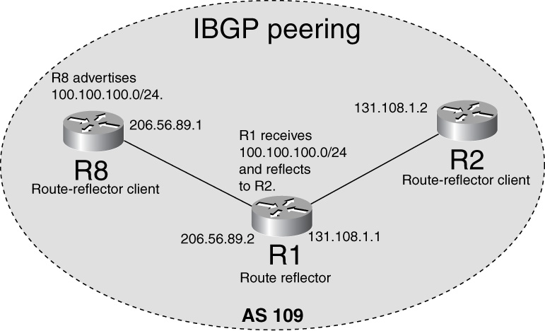
Figure 15-27 Simple Route-Reflection Environment
Debugs and Verification
Example 15-59 shows the required configuration needed to make R1 an RR for R8 and R2. No additional configuration is needed in R8 and R2 to become RRCs other than just the normal IBGP configuration to peer with R1.
Example 15-59 Configuring R1 as a Route Reflector with R8 and R2 as Clients
R1#router bgp 109
no synchronization
neighbor 131.108.1.2 remote-as 109
neighbor 131.108.1.2 route-reflector-client
neighbor 206.56.89.1 remote-as 109
neighbor 206.56.89.1 route-reflector-client
The neighbor IP address must be the same in the route-reflector-client statement as in the remote-as configuration. The Cisco IOS Software BGP parser detects the misconfigured RRC IP address if BGP does not have an IBGP neighbor configured with this address.
For example, if the BGP operator types in this command
R1#
router bgp 109
neighbor 131.108.1.8 route-reflector-client
Cisco IOS Software will immediately display an error:
% Specify remote-as or peer-group commands first
BGP detects that 131.108.1.8 is not configured as a neighbor, so it cannot be associated as an RRC.
Use the show ip bgp neighbor command, as demonstrated in Example 15-60, to verify that the neighbor is configured as an RRC.
Example 15-60 Verifying Neighbor Configuration as an RRC
R1# show ip bgp neighbor 131.108.1.2
BGP neighbor is 131.108.1.2, remote AS 1, internal link
Index 1, Offset 0, Mask 0x2
Route-Reflector Client
Solution
A BGP operator accidentally might configure a different IP address in the RRC than is configured in the neighbor statement where the remote AS is configured. If this problem is detected, the IP address must be corrected.
Problem: Route-Reflector Client Stores an Extra BGP Update—Cause: Client-to-Client Reflection
The problem here stems from RRCs receiving extra BGP updates, which consume extra memory and take up CPU to process them.
In Figure 15-28, RRC R8 peers IBGP with RR R1; R8 is peering IBGP with RRC R2 as well. Because of this peering relationship, R2 receives an extra BGP update for all the routes originated/propagated by R8. Such a setup typically is done when a physical circuit exists between RRCs and the BGP operator wants to run BGP directly over them. In standard network design, such BGP connections between RRCs do not exist, and all RRCs simply peer with their respective route reflector(s) only.

Figure 15-28 Client-to-Client IBGP Peering in Addition to Route Reflector Setup
Figure 15-29 shows the flowchart to follow to resolve this problem.

Figure 15-29 Problem-Resolution Flowchart
Debugs and Verification
The output in Example 15-61 shows that R2 is receiving two updates for 100.100.100.0, one from R8 and another reflected from R1.
Example 15-61 R2’s BGP Table Indicates Updates Received from Both the RR and Another RRC
R2#show ip bgp 100.100.100.0
BGP routing table entry for 100.100.100.0/24, version 3
Paths: (2 available, best #1, table Default-IP-Routing-Table)
Not advertised to any peer
Local
131.108.10.8 (metric 20) from 131.108.10.8 (131.108.10.8)
Origin IGP, metric 0, localpref 100, valid, internal, best
Local
131.108.10.8 (metric 20) from 131.108.10.1 (131.108.10.1)
Origin IGP, metric 0, localpref 100, valid, internal
Originator: 131.108.10.1, Cluster list: 0.0.0.109
Solution
Turning off client-to-client reflection solves this problem. This problem arises only when an RRC peers IBGP with another RRC. When an RRC peers only with the RR, BGP does not run into this issue. Example 15-62 shows the configuration needed on an RR to turn off client-to-client reflection.
Example 15-62 Disabling Client-to-Client Reflection
R1#router bgp 109
no bgp client-to-client reflection
After enabling this command, the RR does not reflect any update from one RRC to another RRC, but it does reflect to normal IBGP and EBGP neighbors. The BGP operator must be certain that RRCs are peering BGP with other RRCs to make this modification.
When R1 is configured in this manner, it does not advertise 100.100.100.0/24 to the other client, R8, but does advertise to other IBGP and EBGP neighbors. Example 15-63 shows that R1 is receiving 100.100.100.0/24 from R8 but is not propagating further to anyone.
Example 15-63 R1’s BGP Table Ensures That Disabling Client-to-Client Reflection Is Successful
R1#show ip bgp 100.100.100.0
BGP routing table entry for 100.100.100.0/24, version 2
Paths: (1 available, best #1, table Default-IP-Routing-Table)
Flag: 0x208
Not advertised to any peer
Local, (Received from a RR-client)
131.108.10.8 from 131.108.10.8 (131.108.10.8)
Origin IGP, metric 0, localpref 100, valid, internal, best
Problem: Convergence Time Improvement for RR and Clients—Cause: Use of Peer Groups
When an RR is serving many clients, any update that it receives from IBGP/EBGP peers must be generated and propagated as separate updates for each RRC. If the number of BGP updates and RRCs is large, this process could become CPU-intensive for the RR. This results in slower propagation of BGP updates and hence results in slower convergence in the network overall. Peer-group clubs configure BGP neighbors in one group. Any common update that needs to go to all members of the peer group are processed only once, and all members receive the copy of that processed update. A router that has a peer group does not process update for all members of the group, resulting in huge CPU processing savings. Overall convergence of the networks improves greatly.
Figure 15-30 shows a route-reflection environment in which peer groups can be used.

Figure 15-30 Peer Group Efficiency in Advertising Routes
Figure 15-31 shows the flowchart to follow to resolve this problem.
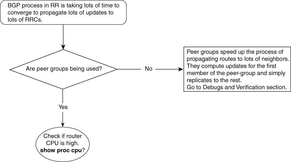
Figure 15-31 Problem-Resolution Flowchart
Debugs and Verification
Typically, peer groups contain several clients to explain the peer group usage. Example 15-64 shows the necessary configuration required by R1 to put R8 and R6 in a peer group named INTERNAL.
Example 15-64 Configuring R8 and R6 as Peer Group Members
R1#router bgp 109
no synchronization
neighbor INTERNAL peer-group
neighbor 131.108.10.8 remote-as 109
neighbor 131.108.10.8 update-source Loopback0
neighbor 131.108.10.8 peer-group INTERNAL
neighbor 131.108.10.6 remote-as 109
neighbor 131.108.10.6 update-source Loopback0
neighbor 131.108.10.6 peer-group INTERNAL
R1 calculates one update for the first member of the peer group INTERNAL and replicate to others. Output in Example 15-65 shows that 131.108.10.8 (R8) is the first member in the list; therefore, R1 calculates updates for R8 and replicates to the rest of the members in the list INTERNAL, to avoid calculating for the rest.
In Example 15-65, R6 is the other member in the list INTERNAL.
Example 15-65 Displaying Peer Group Members
R1#show ip bgp peer-group INTERNAL
BGP peer-group is INTERNAL
BGP version 4
Default minimum time between advertisement runs is 5 seconds
BGP neighbor is INTERNAL, peer-group internal, members:
131.108.10.8 131.108.10.6
Index 1, Offset 0, Mask 0x2
Update messages formatted 4, replicated 2
Solution
When peering to several neighbors, use the Cisco IOS Software BGP peer group feature to avoid the processing duplication required to generate the same update to every neighbor. In peer groups, BGP neighbors (in this case, all RRCs) are listed as members of a peer group that share the same outbound policy. RR computes an update for the first member of the peer group and simply replicates the same update to all members. This greatly reduces the number of CPU cycles that the RR has to spend to compute update for each RRC. In addition, using peer groups speeds up the process of propagating BGP updates to RRCs; therefore, RRCs converge faster in case of any churn. Peer groups can be used in normal IBGP and EBGP scenarios to get this benefit, with the condition that all peer-group members are configured with same outbound policy.
Problem: Loss of Redundancy Between Route Reflectors and Route-Reflector Client—Cause: Cluster List Check in RR Drops Redundant Route from Other RR
A cluster is made up of an RR and its clients. A cluster can have one or more RR and is identified by a cluster ID that is the router ID of the RR. Because each RR has a unique router ID, each cluster has only one RR by default. Network operators must manually configure identical cluster IDs on two or more RRs to configure them in the same cluster. When a BGP update traverses from an RR to other neighbors, RR adds its cluster ID in the list called the cluster list, which contains all cluster IDs that any BGP update has traversed. The cluster list is synonymous with the AS_PATH list, which contains AS lists that any update has traversed. Just as in AS_PATH loop detection, in which updates are dropped if the AS_PATH contains a local AS, the cluster list detects loops if they contain a local cluster ID.
When a route-reflector client is connected to two different RRs that are in the same cluster, chances are good that the RR will not see the redundant path to the clients.
Figure 15-32 shows two RRs configured in the same cluster. Any update one received from the other that has its own cluster ID in the cluster list will be dropped.
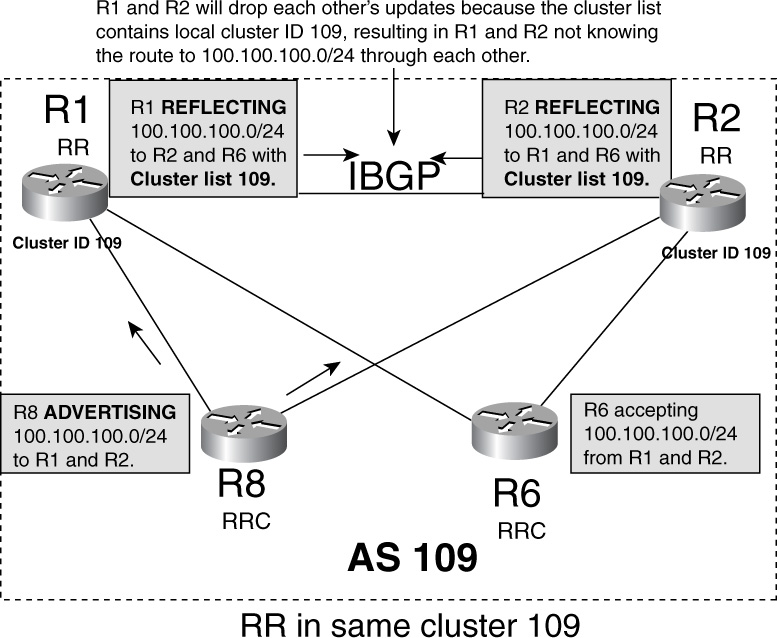
Figure 15-32 Route Reflectors Configured with the Same Cluster ID, Resulting in Loss of Redundancy
Figure 15-32 shows how an RR and an RRC are connected in a single cluster. Each RR must be configured with same cluster ID, as shown in the “Debugs and Verification” section. R8 is advertising 100.100.100.0/24 to its IBGP neighbors R1 and R2, which are RRs for R6 and R8, and reflects 100.100.100.0/24. R1 reflects to R6 and R2, whereas R2 reflects to R1 and R6. Because they both are configured with the same cluster ID 109, the cluster list from both RRs will contain cluster ID 109, represented as 0.0.0.109 in Cisco IOS Software output.
Figure 15-33 illustrates how the RR loses redundancy to the client.

Figure 15-33 How an RR Rejects Routes That Fail the Cluster ID Check
Debugs and Verification
Example 15-66 shows the configuration of the two RRs when they are configured with identical cluster IDs of 109.
Example 15-66 RRs Configured with Identical Cluster IDs
R1# router bgp 109
no synchronization
bgp cluster-id 109
neighbor 172.16.18.8 remote-as 109
neighbor 172.16.18.8 route-reflector-client
neighbor 172.16.126.2 remote-as 109
neighbor 172.16.126.6 remote-as 109
neighbor 172.16.126.6 route-reflector-client
R2# router bgp 109
no synchronization
bgp cluster-id 109
neighbor 172.10.28.8 remote-as 109
neighbor 172.10.28.8 route-reflector-client
neighbor 172.16.126.1 remote-as 109
neighbor 172.16.126.6 remote-as 109
neighbor 172.16.126.6 route-reflector-client
As depicted in Figure 15-33, R8, an RRC, advertises 100.100.100.0/24 to both of its RRs, R1 and R2. When R1 and R2 are configured with the same cluster ID, R1 and R2 have only a single update in their BGP table for 100.100.100.0/24, learned from the RRC itself.
Example 15-67 shows that the RRs have only a single entry in their BGP tables for network 100.100.100.0/24, and this entry is from the RRC.
Example 15-67 RRs R1 and R2 Have Only One Update for 100.100.100.0/24, Resulting in Loss of Redundancy
R1#show ip bgp 100.100.100.0
BGP routing table entry for 100.100.100.0/24, version 2
Paths: (1 available, best #1, table Default-IP-Routing-Table)
Flag: 0x208
Advertised to non peer-group peers:
131.108.10.2 131.108.10.6
Local, (Received from a RR-client)
131.108.10.8 from 131.108.10.8 (131.108.10.8)
Origin IGP, metric 0, localpref 100, valid, internal, best
R1#
R2#show ip bgp 100.100.100.0
BGP routing table entry for 100.100.100.0/24, version 2
Paths: (1 available, best #1, table Default-IP-Routing-Table)
Advertised to non peer-group peers:
131.108.10.1 131.108.10.6
Local, (Received from a RR-client)
131.108.10.8 from 131.108.10.8 (131.108.10.8)
Origin IGP, metric 0, localpref 100, valid, internal, best
Each RR has an update for 100.100.100.0/24 only from R8, not from the other RR.
Example 15-68 shows the output of debug ip bgp update from R2. Notice that R2 is dropping the update for 100.100.100.0/24 from R1 because it sees its own cluster ID, 109, (represented as 0.0.0.109) in the cluster list.
Example 15-68 debug ip bgp update Command Output from R2
R1# debug ip bgp update
*Mar 3 11:29:11: BGP(0): 172.16.10.8 rcvd UPDATE w/ attr: nexthop 172.16.10.8,
origin i, localpref 100, metric 0
*Mar 3 11:29:11: BGP(0): 172.16.10.8 rcvd 100.100.100.0/24
*Mar 3 11:29:11: BGP(0): Revise route installing 100.100.100.0/24 -> 172.16.10.
8 to main IP table
*Mar 3 11:29:11: BGP: 172.16.126.1 RR in same cluster. Reflected update dropped
*Mar 3 11:29:11: BGP(0): 172.16.126.1 rcv UPDATE w/ attr: nexthop 172.16.10.8,
origin i, localpref 100, metric 0, originator 172.16.8.8, clusterlist 0.0.0.109,
path , community , extended community
*Mar 3 11:29:11: BGP(0): 172.16.126.2 rcv UPDATE about 100.100.100.0/24-- DENIED
due to: reflected from the same cluster;
Solution
If a link or IBGP connection between R8 and R2 goes down, R2 has no way to reach 100.100.100.0/24. This is because R2 has rejected the 100.100.100.0/24 advertisement from R1 as a result of the cluster list check.
It is recommended that in cases similar to those depicted in Figure 15-33, RRs should not be put in the same cluster. The cluster ID will be picked as the router ID (RID) of each RR and is guaranteed to be unique because all RIDs are unique in any network.
Example 15-69 shows the configuration of all RRs and RRCs, which are in different clusters. Example 15-69 also shows the configuration in R8 to advertise 100.100.100.0/24 to R1 and R2. Example 15-69 displays the output from the BGP table. Output from R1 and R2 shows that each has a redundant path for 100.100.100.0/24, one directly to R8 and the other one through each other. If a link or BGP session between R1 and R8 is lost, R1 has a backup path through R2 to reach R8.
Example 15-69 Unique Router ID of Each RR Will Make Unique Cluster ID per RR
R1# router bgp 109
no synchronization
neighbor 131.108.10.8remote-as 109
neighbor 131.108.10.8route-reflector-client
neighbor 131.108.10.6remote-as 109
neighbor 131.108.10.6route-reflector-client
neighbor 131.108.10.2remote-as 109
R2# router bgp 109
no synchronization
neighbor 131.108.10.8remote-as 109
neighbor 131.108.10.8route-reflector-client
neighbor 131.108.10.6remote-as 109
neighbor 131.108.10.6route-reflector-client
neighbor 131.108.10.1remote-as 109
R8# router bgp 109
no synchronization
neighbor 131.108.10.1remote-as 109
neighbor 131.108.10.2remote-as 109
R6# router bgp 109
no synchronization
neighbor 131.108.10.1remote-as 109
neighbor 131.108.10.2remote-as 109
R8# router bgp 109
no synchronization
network 100.100.100.0 mask 255.255.255.0
neighbor 131.108.10.1 remote-as 109
neighbor 131.108.10.2remote-as 109
!
ip route 100.100.100.0 255.255.255.0 Null0
R8#show ip bgp 100.100.100.0
BGP routing table entry for 100.100.100.0/24, version 6
Paths: (1 available, best #1, table Default-IP-Routing-Table)
Flag: 0x208
Advertised to non peer-group peers:
131.108.10.1 131.108.10.2
Local
0.0.0.0 from 0.0.0.0 (131.108.10.8)
Origin IGP, metric 0, localpref 100, weight 32768, valid, sourced, local,Best
R1#show ip bgp 100.100.100.0
BGP routing table entry for 100.100.100.0/24, version 2
Paths: (2 available, best #2, table Default-IP-Routing-Table)
Advertised to non peer-group peers:
131.108.10.2 131.108.10.6 Local
131.108.10.8 (metric 20) from 131.108.10.2 (131.108.10.8)
Origin IGP, metric 0, localpref 100, valid, internal
Originator: 131.108.10.8, Cluster list: 131.108.10.2
Local, (Received from a RR-client)
131.108.10.8 from 131.108.10.8 (131.108.10.8)
Origin IGP, metric 0, localpref 100, valid, internal, best
R2#show ip bgp 100.100.100.0
BGP routing table entry for 100.100.100.0/24, version 2
Paths: (2 available, best #2, table Default-IP-Routing-Table)
Advertised to non peer-group peers:
172.16.126.1 172.16.126.6
Local
131.108.10.8 (metric 20) from 131.108.10.1 (131.108.10.8)
Origin IGP, metric 0, localpref 100, valid, internal
Originator: 131.108.10.8, Cluster list: 131.108.10.1 Local, (Received from a
RR-client)
131.108.10.8 from 131.108.10.8 (131.108.10.8)
Origin IGP, metric 0, localpref 100, valid, internal, best
Both R1 and R2 have a redundant path to reach 100.100.100.0/24 only because of a unique cluster ID. The example shows picking a unique cluster ID from a unique router ID; an alternate way to ensure cluster ID uniqueness would be to manually configure a unique cluster ID per RR.
Troubleshooting Outbound IP Traffic Flow Issues Because of BGP Policies
BGP’s real power is in managing IP traffic flows coming in and going out of the AS. BGP in general and Cisco IOS Software in particular offer a great deal of flexibility in manipulating BGP attributes LOCAL_PREFERENCE, MED, and so forth to control BGP best-path calculation. This best-path decision determines how traffic exits the AS. With the large size of BGP networks today, it is crucial that BGP operators understand how BGP attributes should be managed.
This section discusses what problems can arise while trying to manage traffic leaving the AS.
Here is the list of the most common problems encountered in managing outbound traffic flow:
• Multiple exit points exist, but traffic goes out through one or a few exit routers.
• Traffic takes a different interface from what is shown in the routing table.
• A multiple BGP connection exists to the same BGP neighbor, but traffic goes out through only one connection.
• Asymmetrical routing occurs and it causes a problem especially when NAT and time-sensitive applications are used.
Problem: Multiple Exit Points Exist but Traffic Goes Out Through One or Few Exit Routers—Cause: BGP Policy Definition Causes Traffic to Exit from One Place
This problem commonly is seen when an AS receives the same prefix announcements from multiple EBGP connections but traffic destined to those prefixes prefers only one or two exit points.
As illustrated by Figure 15-34, AS 109 has multiple connections to other autonomous systems. AS 109 has three EBGP connections with AS 110, two with AS 111, and one with AS 112. AS 111 is peering with AS 110 and AS 112.
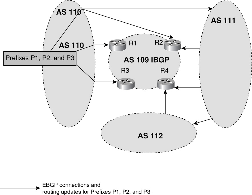
Figure 15-34 Autonomous System with Multiple Connections to Other Autonomous Systems with Multiple Exit Points
Prefixes P1, P2, and P3 are originated by AS 110 and are advertised to EBGP neighboring autonomous systems 109, 111, and 112. AS 109 receive updates for these prefixes from multiple locations—three updates from AS 110, two from AS 111, and one from AS 112. Even with such redundant BGP advertisements for Prefixes P1, P2, and P3, all the traffic for these prefixes from AS 110 might take only one or two exit points. The rest of the connections are underutilized. Such a scenario typically results in overutilized links because traffic tends to exit from one or two preferred paths, as governed by BGP policy of AS 109.
Figure 15-35 shows the flowchart to follow to resolve this problem.
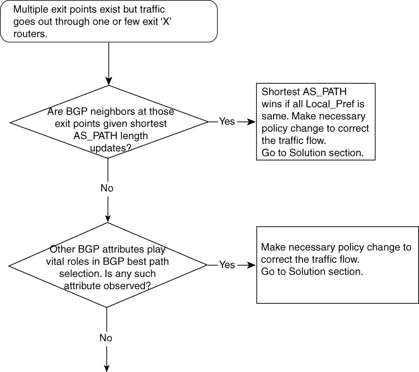
Figure 15-35 Problem-Resolution Flowchart
AS 109 BGP installs its best path for Prefixes P1, P2, and P3 in the IP routing table, and traffic destined for these prefixes will look in the routing tables for routers in AS 109. It is crucial to understand how BGP selects the best path; to do this, BGP operators must understand how BGP path attributes work. These attributes include AS_PATH, LOCAL_PREFERENCE, MED, ORIGIN, and so on, as discussed in detail in Chapter 14.
This section discusses how AS_PATH affects traffic patterns in AS 109 for Prefixes P1, P2, and P3. It is assumed that AS 109 is not configured with any additional BGP policies.
Recall that AS_PATH contains a list of autonomous systems that an update has traversed.
This section shows the AS_PATH list of R1 and R4 as an example; you are encouraged to come up with the AS_PATH list for R2 and R3 as an exercise.
R1 has two updates for Prefixes P1, P2, and P3 and the AS_PATH would like the following:
• 110—Path from a direct connection between R1 and AS 110. This would be an EBGP path with an AS_PATH length of 1.
• 110—Path from R2. This would be an IBGP path with an AS_PATH length of 1.
Out of these two paths, the first one will be selected as best because, with the same AS_PATH length, the EBGP path is better than the IBGP path.
R4 AS_PATH would like the following:
• 112 111 110—Path from R4 and AS 112 connection. This is an EBGP path with an AS_PATH length of 3.
• 111 110—Path from R4 and AS 111 connection. This is an EBGP path with an AS_PATH length of 2.
• 110—Path from R1. This would be an IBGP path with an AS_PATH length of 1.
• 110—Path from R2. This would be an IBGP path with an AS_PATH length of 1.
• 110—Path from R3. This would be an IBGP path with an AS_PATH length of 1.
The AS_PATH length of the third, fourth, and fifth paths is 1, and best-path selection will be based on IBGP next-hop cost through the IGP. If you assume that the third path from R1 wins, all traffic from R4 destined for Prefixes P1, P2, and P3 will exit from R1 and the AS 110 connection, leaving path 1, 2, 4, and 5 links not used at all for Prefixes P1, P2, and P3.
Refer back to Chapter 14 for the full description of how the best-path calculation method works.
This example could be a real-life one in which AS 110 is a big Tier 1 ISP that peers BGP with just about all other ISPs, big or small. Chances are, AS 110 will provide AS 109 with most of the BGP prefixes (P1, P2, and P3) with the shortest AS_PATH. This will influence AS 109’s BGP best-path procedure to pick AS 110 as the first preference to carry traffic for P1, P2, and P3, which, in turn, results in clogging links that connect AS 109 to AS 110 directly. Because AS 109 has not made any BGP policy change for P1, P2, and P3, AS 109 is at the mercy of BGP neighbors and is left with no control of traffic flow from its AS 109 to P1, P2, and P3. The links from AS 109 to AS 111, 112, and so forth are used minimally, resulting in wasted high-cost bandwidth.
Solution
If a situation arises in which one BGP neighbor (AS 110, in this example) is attracting all the traffic from AS 109 to Prefixes P1, P2, and P3, AS 109 BGP operators should define local policies within AS 109 to overcome this behavior.
Using the BGP attribute LOCAL_PREFERENCE is done commonly to predictably control the traffic leaving the local AS (AS 109, in this example). AS 109 can choose to make AS 111 and AS 112 carry traffic for Prefix P2 and P3, respectively, and can leave the rest for AS 110.
Example 15-70 shows an example of how R2 in AS 109 can change LOCAL_PREFERENCE on a per-prefix basis with a neighbor in AS 111 to make AS 111 attract all the traffic for P2.
Example 15-70 Implementing the LOCAL_PREFERENCE Attribute to Control the Traffic Flow
R2#
router bgp 109
neighbor 172.16.1.1 remote-as 111
neighbor 172.16.1.1 route-map influencing_traffic in
access-list 1 permit P2 wild_card
access-list 2 permit any
route-map influencing_traffic permit 10
match ip address 1
set local-preference 200
!
route-map influencing_traffic permit 20
match ip address 2
set local-preference 90
Access list 1 is permitting Prefix P2. The actual access list would have the real IP prefix; P2 is used just for illustration purposes. The first sequence 10 of route-map influencing_traffic allows P2 to be set with a LOCAL_PREFERENCE of 200, and sequence 20 of the same route map sets a LOCAL_PREFERENCE of 90 for the other prefixes (P1 and P3). This results in making P2’s LOCAL_PREF 200, thus making AS 111 path the best path for P2 only. Setting the P1 and P3 LOCAL_PREF attributes to 90 would have no effect because, in Cisco IOS Software, the default value for LOCAL_PREFERENCE is 100; AS 110 will be picked as the best path for P1 and P3.
With the size of the BGP routing table today, it is difficult to manage traffic on a prefix-by-prefix basis. Typically, BGP speakers change the LOCAL_PREFERENCE value based on the AS_PATH list. AS 109 might decide that all prefixes that come from AS 111 that have in the AS_PATH list either “111” or “111 and one more AS” should be selected as best paths through AS 111 neighbors. Therefore, AS 110 and AS 112 should not be the preferred carriers for prefixes that are originated by AS 111 or that are coming from an AS directly peering with AS 111.
Manipulating BGP attributes (LOCAL_PREFERENCE) based on AS_PATH list requires the use of the as_path access-list command, which uses UNIX-like regular expressions.
Example 15-71 shows a configuration example of Router R2 in AS 109 that changes the LOCAL_PREFERENCE of all the prefixes of those received from AS 111 that have in the AS_PATH list either “111” or “111 and one more AS.”
Example 15-71 LOCAL_PREFERENCE Manipulation Using AS_PATH List
R2#
router bgp 109
neighbor 172.16.1.1 remote-as 111
neighbor 172.16.1.1 route-map influencing_traffic in
!
ip as-path access-list 1 permit ^111$
ip as-path access-list 1 permit ^111 [0-9]+$
ip as-path access-list 2 permit .*
route-map influencing_traffic permit 10
match as-path 1
set local-preference 200
!
route-map influencing_traffic permit 20
match as-path 2
set local-preference 90
The first sequence number, 10, of route-map influencing_traffic looks at AS path 1, which permits any prefix that has in its AS_PATH list either “111” or “111 and one more AS”; it then sets the LOCAL_PREFERENCE to 200, making links to AS 111 the preferred path from the AS 109 BGP view. The regular expression ^111$ means that AS_PATH should contain only one AS, and that is AS 111.
The expression ^111 [0-9]+$ means that AS_PATH should contain two autonomous systems, but the first one must be AS 111; the second one can be any AS. The expression .* means any AS.
The second sequence number, 20, of route-map influencing_traffic looks at AS path 2, which permits everything and makes the LOCAL_PREFERENCE lower than the default of 100 so that other carriers can pick the rest of the traffic.
BGP attribute manipulation based on AS_PATH is a fairly common practice among savvy BGP operators because wildcard operations allow covering a larger number of prefixes to be checked in fewer lines of configuration.
In essence, it is crucial that BGP operators manage their traffic flow by making necessary BGP attribute changes to influence the BGP path-selection process. This ensures predictable traffic management within an AS and allows future upgrades in bandwidth to easily be judged.
Problem: Traffic Takes a Different Interface from What Shows in Routing Table—Cause: Next Hop of the Route Is Reachable Through Another Path
In some scenarios, BGP and the routing table path to a certain destination prefix show Exit A, but actual traffic leaves through Exit B. Packet forwarding to a destination takes place from the routing table, and network operators do expect to see this behavior. However, in most cases, the next hops of prefixes in the routing table are not directly connected and packet forwarding eventually takes place based on the next-hop path. Figure 15-36 tries to explain one such simple case.

Figure 15-36 Packet Might Take a Different Physical Path Than What the IP Routing Table Shows
Figure 15-36 shows that R1 and R2 are two route reflectors, with R6 and R8 as their clients. R6 is advertising 100.100.100.0/24 to R2 and R1, and both reflect this advertisement to R8 with a next hop of 172.16.126.6. Now, assume that R8 has a BGP policy that chooses the path for 100.100.100.0/24 from R2 (the upper path) as the best path that it will install in its routing table. However, in the same router, R8, the best IGP path to reach 172.16.126.6 (next hop of 100.100.100.0/24) is through R1 (the bottom path).
All traffic destined from or through R8 to 100.100.100.0/24 will take the bottom path; even though the best BGP-selected path in the routing table is the upper path, it will not be used.
Therefore, forwarding of IP packets in a router eventually happens by looking at the path for the next hop (172.16.126.6) of the actual path (100.100.100.0/24). In Cisco IOS Software, recursive lookup is the term used for finding out the path based on the next hop and the actual prefix. In some cases, more than one recursive lookup must be done to figure out the actual physical path that packets take to reach the destination.
Figure 15-37 shows the flowchart to follow to resolve this problem.

Figure 15-37 Problem-Resolution Flowchart
Debugs and Verification
Example 15-72 shows the output of 100.100.100.0/24 in R8. The next hop is 172.16.126.6. When traffic is sent to 100.100.100.0/24, it actually is sent to the interface that provides a better route for 172.16.126.6.
Example 15-72 BGP and Routing Table Output for 100.100.100.0/24 Shows Best Path Through R2
R8#show ip bgp 100.100.100.0
BGP routing table entry for 100.100.100.0/24, version 5870
Paths: (1 available, best #1, table Default-IP-Routing-Table)
Not advertised to any peer
Local
172.16.126.6 (metric 20) from 172.16.126.2 (172.16.126.2)
Origin IGP, metric 0, localpref 100, valid, internal, best
In R8, 172.16.126.6 is the next hop for 100.100.100.0/24 advertised by R2 and is considered the best route; therefore, it will be installed in the IP routing table.
Example 15-73 shows that the best way to reach 172.16.126.6, the next hop of 100.100.100.0/24, is through R1, not through R2.
Example 15-73 show ip route Command Output Shows the Best Route to Reach 172.16.126.6
R8#show ip route 172.16.126.6
Routing entry for 172.16.126.0/24
Known via "static", distance 1, metric 0
Routing Descriptor Blocks:
* 172.16.18.1
Route metric is 0, traffic share count is 1
The highlighted 172.16.18.1 is the next hop for 172.16.126.6 (next hop of 100.100.100.0/24).
Therefore, all traffic from or through R8 destined for 100.100.100.0/24 will go through 172.16.18.1 (R1).
Example 15-74 shows the output of a traceroute done from R8 to 100.100.100.1. The traffic flows through 172.16.18.1, which is R1.
Example 15-74 traceroute Command Output Shows Traffic Going from R1 Instead of R2
R8#traceroute 100.100.100.1
Type escape sequence to abort.
Tracing the route to 100.100.100.1
1 172.16.18.1 4 msec 4 msec 4 msec
2 172.16.126.6 4 msec 8 msec 8 msec
3 172.16.126.6 4 msec 8 msec 8 msec
Solution
A router might provide a route to BGP neighbor but might never be in a forwarding path to reach that route. This is because packets are forwarded to the next-hop address of the actual route, which might not be the same router that gave the route in the first place.
If routing and forwarding paths need to match, care must be taken in how next-hop addresses are learned through IGP. To fix the problem in Figure 15-36, R8 should have an IGP path for 172.16.126.6 (next hop of 100.100.100.0/24) through R2.
Problem: Multiple BGP Connections to the Same BGP Neighbor AS, but Traffic Goes Out Through Only One Connection—Cause: BGP Neighbor Is Influencing Outbound Traffic by Sending MED or Prepended AS_PATH
Typically, BGP networks are multihomed to different ISPs or the same ISP to provide redundancy or to load-share traffic. In some scenarios, the BGP network might be dual homed to the same ISP and might be running BGP with that ISP. Instead of load sharing traffic to the ISP over multiple connections, traffic might exit only from one connection.
These connections might be of equal bandwidth or might be different.
If the multiple EBGP connection links are of equal bandwidth and traffic exits from only one of those EBGP connections, this is not desirable and can lead to severe performance degradation because of packet loss and round-trip delays over the congested link. If the EBGP connections are of different bandwidth—say, T3 (45 Mbps) and T1 (1.5 Mbps)—it might be desirable for all traffic to go out through the T3 exit point. This section discusses the issue in which all EBGP connections going to the same ISP are of equal bandwidth but traffic goes out from only one of those links.
In the network illustrated in Figure 15-38, AS 109 has three EBGP peerings with AS 110, and AS 110 is advertising the same prefixes, P1, P2, P3, and so forth, at all peering points. However, all traffic from AS 109 destined for these prefixes uses a single exit point, X, with AS 110. This results in congestion at X and unnecessary usage of the AS 109 backbone.

Figure 15-38 BGP Network in Which Traffic Is Routed Inefficiently
Figure 15-39 shows the flowchart to follow to resolve this problem.

Figure 15-39 Problem-Resolution Flowchart
Typically, EBGP speakers agree on sending and accepting MEDs from each other. However, AS 110 might send a lower MED to AS 109 for all its prefixes at connection X. This would result in AS 109 choosing Exit X as a best path to reach Prefixes P1, P2, and P3. Throughout the BGP domain of AS 109, all BGP speakers install Exit X as a next hop for all routes, P1, P2, and P3. All traffic to these prefixes originating or traversing through AS 109 choose Exit X. This results in clogging Exit X, and traffic uses available bandwidth in the AS 109 backbone. Notice that exit points Y and Z are left unused for traffic destined for Prefixes P1, P2, and P3.
Solution
You can address this problem a number of ways:
• Request AS 110 to send the proper MED for each prefix.
• Don’t accept MED from AS 110.
• Manually change LOCAL_PREFERENCE for P1, P2, and P3 at all the exit points, X, Y, and Z.
Request AS 110 to Send the Proper MED for Each Prefix
MED exchange with an EBGP peer is a tricky and bilateral game. Typically, BGP carriers accept MEDs only on a mutual basis in a process in which both carriers accept each other’s MED. Accepting MED means that BGP carriers carry each other’s traffic through the backbone and try to route the traffic in an optimal fashion.
If this mutual agreement takes place between AS 109 and AS 110, AS 109 can request AS 110 to send proper MEDs for prefixes announced. For example, if Prefix P1 is closer to Exit X, AS 110 should send a MED for P1 at X. A similar process should take place for P2 at Y and P3 at Z, if they are closer there. Traffic destined for Prefixes P1, P2, and P3 will ride the AS 109 backbone the most and enter AS 110 at the optimal exit from the AS 109 BGP speaker’s view.
Don’t Accept MED from AS 110
Request AS 110 either to not send the MED or to manually set the MED to 0 at peering points X, Y, and Z and for all prefixes from AS 110. This results in AS 109 picking the closest exit point, X, Y, or Z, for Prefixes P1, P2, and P3 through the lowest IGP (OSPF, IS-IS, and so on) cost to reach these exit points. Manually setting the MED to 0 can be done through a route map, as demonstrated in Example 15-75.
Example 15-75 Manually Setting the MED to 0 to Override Any Advertised MED from AS 110
route-map influencing_traffic permit 10
set metric 0
!
R1# router BGP 109
neighbor 4.4.4.4 remote-as 110
neighbor 4.4.4.4 route-map influencing_traffic in
This route map should be applied at all EBGP connections between AS 109 and AS 110. Example 15-75 shows this route map applied only between R1 and R4.
The configuration in Example 15-75 sets the MED value for all the prefixes from AS 110 to 0. Now, BGP speakers in AS 109 use the IGP cost as a tiebreaker in the BGP best-path selection process. This results in traffic destined to Prefixes P1, P2, and P3 choosing the closest exit point.
Manually Change LOCAL_PREFERENCE for P1, P2, and P3 at All the Exit Points X, Y, and Z
To use this solution, AS 109 must know which exit point is closer to which prefix.
For example, if Prefix P1 is closer to exit point X, AS 109 should make the LOCAL_PREFERENCE higher for Prefix P1 at X. This method can be used for P2 and P3 if they are closer to Y and Z, respectively.
Example 15-76 shows a sample configuration at exit point X to change the LOCAL_PREFERENCE higher for P1 than the default value of 100.
Example 15-76 Setting the LOCAL_PREFERENCE Value Higher to Select the Best Exit Point
R1# router BGP 109
neighbor 4.4.4.4 remote-as 110
neighbor 4.4.4.4 route-map influencing_traffic in
route-map influencing_traffic permit 10
match ip address 1
set local-preference 200
!
route-map influencing_traffic permit 20
set local-preference 100
In Example 15-76, the route map influencing traffic is applied between R1 and R4. Access list 1, not shown, permits Prefix P1 only. Therefore, for P1, the LOCAL_PREF will be 200; for the rest of the prefixes, it will be the default, which is 100. A similar route map with proper prefix permitting in access list 1 needs to be applied at all EBGP connections between AS 109 and AS 110.
With the configuration addition in Example 15-76, Prefix P1 gets a LOCAL_PREF of 200 at R1, and all routers in AS 109 receive Prefix P1 with a LOCAL_PREF of 200. R1 and all routers in AS 109 select R1 as an exit point to reach P1 because of the higher LOCAL_PREFERENCE.
This method does not scale well in large BGP networks in which BGP speakers advertise and receive thousands of prefixes. Changing the LOCAL_PREFERENCE for each prefix could become cumbersome. A situation might arise in which AS 110 Prefixes P1, P2, and P3 also are advertised by another EBGP speaker—say, AS 111. AS 109 might set a higher LOCAL_PREFERENCE for AS 111 than from AS 110. In this situation, traffic from AS 109 destined for P1, P2, and P3 take AS 111 as an exit point, resulting in suboptimal routing. AS 109 must ensure that AS 110 Prefixes P1, P2, and P3 receive higher LOCAL_PREFERENCE from X, Y, and Z.
Problem: Asymmetrical Routing Occurs and Causes a Problem Especially When NAT and Time-Sensitive Applications Are Used—Cause: Outbound and Inbound Advertisement
Asymmetric routing means that packets flowing to a given destination don’t use the same exit point as the packets coming back from that same destination. This is not a problem in itself, but it can cause some issues when Network Address Translation (NAT) or a time-sensitive application is involved.
Symmetrical routing is probably one of hardest network policies to achieve. Figure 15-40 shows a network in which asymmetrical routing occurs.
Figure 15-40 shows a network setup composed of AS 109 and AS 110, and AS 110 has private IP addressing in the 10.0.0.0 network. AS 110 has two exit points, R1 and R2; however, R1 is the only router performing NAT for any packets sourcing from inside AS 110. In Figure 15-40, the 10.1.1.1 private IP address is translated to 131.108.1.1 at R1 when 10.1.1.1 is sending IP traffic to prefix P in AS 109. From the figure, it is obvious that this packet will enter AS 109 at Interface X of Router R3 and that this packet might exit from Interface Y of R4.

Figure 15-40 Network Vulnerable to Asymmetrical Routing
This might happen for multiple reasons and its results could be severe, the most common of which are listed here:
• AS 109 BGP policy might dictate that all AS 110 traffic should exit from Y.
• AS 110 might influence AS 109 by using MED or AS_PATH prepend to receive all traffic from AS 109 at Exit Y.
• AS 109 BGP policy might govern the closest exit policy for all AS 110 traffic. For Router R3 in AS 109, the closest exit is Y, regardless of where the destination, 131.108.1.1, is.
• When R2 receives the returned packet destined for 131.108.1.1, it has no NAT entry to translate back to 10.1.1.1 and it simply drops this packet.
• The link between R1 and R3 is of bigger bandwidth but the link between R2 and R4 has small bandwidth. The return traffic from R2 to R4 could add significant delays in the overall round-trip time of the packet from AS 109 to AS 110.
Debugs and Verification
Because packet drops and sluggish round-trip times are observed in AS 109, administrators in AS 109 must figure out a way to determine if asymmetrical routing is occurring. A simple ping from R1 to Prefix P in AS 110 will not help because reply packets will never arrive back at R1; instead, they will be coming back at R2. Administrators either would have to sniff the packets at R1 using sniffers or would run the debug ip packet command to observe whether the packets are going through R1 to reach Prefix P in AS 110 but are not coming back. Any debugs in Cisco IOS Software must be run with extreme caution because too much output can disturb the performance of the router. If such packet sniffing is done at R2 in AS 109, administrators can observe that packets are returning from Prefix P and are destined to addresses in AS 109. This can assure them that IP traffic is asymmetrical.
Another approach is to use traceroute; however, the problem with traceroute is that it provides the traffic path only in one direction—from source to destination (AS 109 to AS 110). In asymmetrical routing, administrators are more interested in the direction of traffic from destination to source (AS 110 to AS 109). This can be achieved only if AS 110 issues a traceroute to the destination in AS 109 and AS 109 administrators observe the output.
Solution
The asymmetrical routing issue is a fairly difficult problem to tackle and sometimes is unavoidable. Asymmetrical routing might be an issue in cases of NAT when only one device maintains the NAT table; therefore, packets must come in and out of the same device. Time-sensitive applications also might face problems when the exit path offers good throughput but the entry path is sluggish, making the overall round-trip time (RTT) bad.
Asymmetrical routing is easy to tackle in small networks, such as the one shown in Figure 15-40. To illustrate how AS 109 can avoid asymmetrical routing when peering only with AS 110, the following condition must be met:
If a packet leaves from R1 to outside AS 109, it must come back into AS 109 at R1.
How can AS 109 achieve this? AS 110 must know that to reach destinations (131.108.1.0/24) in AS 109, it must use the R3–R1 peering link. The following are viable solutions:
• In the BGP configuration of AS 109, only R1 advertises 131.108.1.0/24 to R3 in AS 110. AS 110 will have only one way to reach 131.108.1.0/24, and that is through the R3–R1 link, ensuring symmetrical routing.
• Both R1 and R2 are running EBGP with R3 and R4, respectively. From R1, advertise 131.108.1.0/24 to R3 with a MED of 1; from R2, advertise 131.108.1.0/24 to R4 with a MED of 20. AS 110 will have two advertisements, but the path from the lower MED (R1) will win and, in case the R1–R3 BGP connection fails, the path from R2 to R4 will be used. The use of the MED is discussed in detail in previous sections.
• Using the as-path prepend option in Cisco IOS Software, R2 advertises 131.108.1.0/24 with the AS_PATH list containing AS 109 several times.
Example 15-77 shows the configuration of R2 to advertise 131.108.1.0/24 with a prepended AS.
Example 15-77 Prepending AS Number to Make an AS_PATH Longer
R2# router bgp 109
network 131.108.1.0 mask 255.255.255.0
neighbor 4.4.4.4 remote-as 110
neighbor 4.4.4.4 route-map SYMMETRICAL out
route-map SYMMETRICAL permit 10
match ip address 1
set as-path prepend 109 109 109
route-map SYMMETRICAL permit 20
access-list 1 permit 131.108.1.0
In R2 using the route map SYMMETRICAL for neighbor R4, R2 is advertising 131.108.1.0/24 through access list 1 and adds in the AS_PATH AS 109 three additional times. When the advertisement goes to R4, the output of BGP is highlighted in Example 15-78.
Example 15-78 BGP Routing Table for R4
R4# show ip bgp 131.108.1.0
BGP routing table entry for 131.108.1.0/24, version 19
Paths: (2 available, best #1, table Default-IP-Routing-Table)
109
3.3.3.3 from 3.3.3.3 (3.3.3.3)
Origin IGP, metric 0, localpref 100, valid, internal, best
109 109 109 109
2.2.2.2 from 2.2.2.2 (2.2.2.2)
Origin IGP, metric 0, localpref 100, valid, external
The second path AS_PATH list contains AS 109 listed four times. One time is for the regular EBGP advertisement from R2, and the three additional paths to AS 109 are because of the AS_PATH prepend done in R2.
The best path is the first path, which came from R3 to R4. It is best because it has a shorter AS_PATH length.
R3 will have the regular single EBGP advertisement from R1, as shown in Example 15-79.
Example 15-79 EBGP Advertisement from R1 to R3
R3#show ip bgp 131.108.1.0
BGP routing table entry for 131.108.1.0/24, version 19
Paths: (1 available, best #1, table Default-IP-Routing-Table)
Advertised to non peer-group peers:
4.4.4.4
109
1.1.1.1 from 1.1.1.1 (1.1.1.1)
Origin IGP, metric 0, localpref 100, valid, external,best
This best path is advertise to R4(4.4.4.4) by R3.
In short, proper BGP announcements must be made at exit points and routes must be learned at the right place of the AS. Smaller enterprise networks can achieve this rather easily with the prepended AS path solution, but larger enterprise and ISP networks face a bigger challenge to ensure symmetrical routing. This is because ISPs have a larger number of prefixes to advertise, a larger number of exit points, and a larger number of BGP peering relationships. Unless symmetrical routing is not a must, especially in the case of NAT, most networks today run fine with asymmetrical routing.
Troubleshooting Load-Balancing Scenarios in Small BGP Networks
Problem: Load Balancing and Managing Outbound Traffic from a Single Router When Dual Homed to Same ISP—Cause: BGP Installs Only One Best Path in the Routing Table
In multihomed scenarios, a common concern that enterprise network operators face is improperly utilizing the external links going to the ISP. Typically, enterprise customers dual-home to either the same or different ISPs to load-share outgoing and incoming traffic.
Figure 15-41 shows a simple setup of R1 of AS 109 dual homed to same ISP AS 110 at R2 and R3. Both R2 and R3 are advertising prefix 100.100.100.0/24 to R1. Ideally, R1 should load-share traffic destined for prefix 100.100.100.0/24, but, by default, this does not happen and only one of the many paths available is used.

Figure 15-41 1AS Dual Homed to Same ISP AS
BGP selects only a single best route for a prefix out of many alternate paths. This is the default behavior governed by RFC 1771. R1 will have two paths for prefix 100.100.100.0/24—one from R2 and the other from R3. R1 will go through its BGP best-path calculation and will pick and install one route in the routing table.
Figure 15-42 shows the flowchart to follow to resolve this problem.

Figure 15-42 Problem-Resolution Flowchart
Debugs Verification
Example 15-80 shows output in R1 receiving two paths for prefix 100.100.100.0/24 but installing only one.
Example 15-80 Output of R1 Having Multiple Paths for 100.100.100.0/24 but Installing Only One in Its Routing Table
R1#show ip bgp 100.100.100.0
BGP routing table entry for 100.100.100.0/24, version 2
Paths: (2 available, best #2)
Not advertised to any peer
110
141.108.1.3 from 141.108.1.3 (1.2.1.1)
Origin IGP, metric 0, localpref 100, valid, external
110
141.108.1.1 from 141.108.1.1 (141.108.6.1)
Origin IGP, metric 0, localpref 100, valid, external, best
R1#show ip route 100.100.100.0
Routing entry for 100.100.100.0/24
Known via "bgp 109", distance 20, metric 0
Tag 110, type external
Last update from 141.108.1.1 00:32:25 ago
Routing Descriptor Blocks:
* 141.108.1.1, from 141.108.1.1, 00:32:25 ago
Route metric is 0, traffic share count is 1
AS Hops 1
Solution
Fortunately, Cisco IOS Software allows, by configuration, the installation of more than one route for the same prefix, as demonstrated in Example 15-81. This does come with a tight check: Multiple paths that are candidates to go in the routing table have the exact same BGP attribute except for the router ID (RID). If two or more paths have identical attributes except for the RID, they can go in the routing table and load sharing can be achieved for traffic going to that prefix.
Example 15-81 Configuration Addition in R1 to Allow Multiple Paths to Be Installed in the Routing Table for 100.100.100.0/24
R1# router bgp 109
neighbor 141.108.1.1 remote-as 110
neighbor 141.108.1.3 remote-as 110
maximum-paths 2
R1#show ip bgp 100.100.100.0
BGP routing table entry for 100.100.100.0/24, version 2
Paths: (2 available, best #2)
Not advertised to any peer
110
141.108.1.3 from 141.108.1.3 (1.2.1.1)
Origin IGP, metric 0, localpref 100, valid, external, multipath
110
141.108.1.1 from 141.108.1.1 (141.108.6.1)
Origin IGP, metric 0, localpref 100, valid, external, best, multipath
The maximum-path 2 command allows two equal BGP paths to be installed in the routing table. Cisco IOS Software allows a maximum of six equal paths. Notice that in the BGP output, only one path has “best” in its output, but both have “multipath” and thus both will be installed in the routing table, as shown in the output of Example 15-82.
Example 15-82 Multiple Paths for 100.100.100.0/24 in the Routing Table
R1# show ip route 100.100.100.0
Routing entry for 100.100.100.0/24
Known via "bgp 109", distance 20, metric 0
Tag 110, type external
Last update from 88.88.88.78 00:34:36 ago
Routing Descriptor Blocks:
* 141.108.1.1, from 141.108.1.1, 00:34:36 ago
Route metric is 0, traffic share count is 1
AS Hops 1
141.108.1.3, from 141.108.1.3, 00:34:36 ago
Route metric is 0, traffic share count is 1
AS Hops 1
Traffic from R1 sent to 100.100.100.0/24 will use both BGP connections, thus load sharing across dual-homed connections.
Problem: Load Balancing and Managing Outbound Traffic in an IBGP Network—Cause: By Default, IBGP in Cisco IOS Software Allows Only a Single Path to Get Installed in the Routing Table Even Though Multiple Equal BGP Paths Exist
If multiple paths are received from different IBGP neighbors for the same prefix, only one best path will be selected and installed in the routing table. This results in other alternate paths being unused.
Figure 15-43 shows a simple IBGP network in which R1 has an IBGP peering with R2 and R3. Both R2 and R3 are advertising 100.100.100.0/24 with next hops of 2.2.2.2 and 3.3.3.3, respectively, to R1. By default, R1 goes through its BGP best-path calculation and installs a single route for 100.100.100.0/24. Two paths exist, but only one sends traffic to 100.100.100.0/24.

Figure 15-43 IBGP Network with IBGP Peering to Two Routers
Figure 15-44 shows the flowchart to follow to resolve this problem.

Figure 15-44 Problem-Resolution Flowchart
Debugs and Verification
Example 15-83 shows output in R1 receiving two IBGP paths for prefix 100.100.100.0/24 but installing only one.
Example 15-83 Output of R1 Having Multiple IBGP Paths for 100.100.100.0/24 but Installing Only One in Its Routing Table
R1#show ip bgp 100.100.100.0
BGP routing table entry for 100.100.100.0/24, version 2
Paths: (2 available, best #1)
Not advertised to any peer
110
2.2.2.2(metric 11) from 2.2.2.2 (2.2.2.2)
Origin IGP, metric 0, localpref 100, valid, internal, best
110
3.3.3.3(metric 11) from 3.3.3.3 (3.3.3.3)
Origin IGP, metric 0, localpref 100, valid, internal
R1#show ip route 100.100.100.0
Routing entry for 100.100.100.0/24
Known via "bgp 109", distance 200, metric 0
Tag 110, type internal
Last update from 2.2.2.2 00:32:25 ago
Routing Descriptor Blocks:
2.2.2.2, from 2.2.2.2, 00:32:25 ago
Route metric is 0, traffic share count is 1
AS Hops 1
Solution
Cisco IOS Software allows, by configuration, the selection of multiple IBGP paths for the same prefix to go in the routing table, as demonstrated in Example 15-84.
Example 15-84 Configuration Addition in R1 to Allow Multiple IBGP Paths to Get Installed in the Routing Table for 100.100.100.0/24
R1# router bgp 109
neighbor 2.2.2.2 remote-as 109
neighbor 3.3.3.3 remote-as 109
neighbor 2.2.2.2 update-source loopback0
neighbor 3.3.3.3 update-source loopback0
maximum-paths ibgp 2
maximum-paths ibgp 2 allows two IBGP-learned paths to be installed in the routing table, and both paths are used in carrying traffic for 100.100.100.0/24. For maximum-paths ibgp to work, the following conditions must be met:
• In both paths, all BGP attributes—LOCAL_PREF, MED,ORIGIN, and AS_PATH (entire AS_PATH)—must be identical.
• Both paths must be learned through IBGP.
• Both paths must be synchronized.
• Both paths must have a reachable next hop.
• Both paths must have an EQUAL IGP cost to the next hop.
Example 15-85 shows the output of BGP table in R1 after applying the maximum-paths ibgp command.
Example 15-85 Effect of Applying maximum-paths ibgp Command in R1
R1#show ip bgp 100.100.100.0
BGP routing table entry for 100.100.100.0/24, version 2
Paths: (2 available, best #2)
Not advertised to any peer
110
2.2.2.2 from 2.2.2.2 (2.2.2.2)
Origin IGP, metric 0, localpref 100, valid, internal, best, multipath
110
3.3.3.3 from 3.3.3.3 (3.3.3.3)
Origin IGP, metric 0, localpref 100, valid, internal, multipath
Both of these paths are marked as “multipath” in the highlighted BGP output, and both will be installed in the routing table, as shown in Example 15-86.
Example 15-86 Multiple IBGP Paths for 100.100.100.0/24 in the Routing Table of R1
R1# show ip route 100.100.100.0
Routing entry for 100.100.100.0/24
Known via "bgp 109", distance 200, metric 0
Tag 109, type internal
Last update from 88.88.88.78 00:34:36 ago
Routing Descriptor Blocks:
* 2.2.2.2, from 2.2.2.2, 00:34:36 ago
Route metric is 0, traffic share count is 1
AS Hops 1
3.3.3.3, from 3.3.3.3 00:34:36 ago
Route metric is 0, traffic share count is 1
AS Hops 1
Traffic from R1 sent to 100.100.100.0/24 will use both IBGP connections, thus load sharing across multiple IBGP connections.
Troubleshooting Inbound IP Traffic Flow Issues Because of BGP Policies
Just as in managing outbound IP traffic from an AS, Cisco IOS Software offers BGP operators configuration options to manage inbound traffic in an AS. It is important that inbound traffic from other autonomous systems be managed well. If this does not happen, capacity of the network will not be fully utilized. This causes congestion in one part of the network while the other parts are underutilized. The end result of this mismanagement of inbound traffic flow is sluggish throughput, slow round-trip times, and delays in IP traffic. Therefore, it is essential that all inbound BGP policies are checked and configured correctly.
Some of the most common problems in managing inbound IP traffic in an AS using BGP are as follows:
• Multiple connections exist to an AS, but all the traffic comes in through one BGP neighbor, X, in the same AS.
• A BGP neighbor in AS 110 should just be a backup provider, but some traffic from Internet still comes through AS 110.
• Asymmetrical routing occurs.
• Traffic to a certain subnet should come through a particular connection, but it is coming from somewhere else.
Problem: Multiple Connections Exist to an AS, but All the Traffic Comes in Through One BGP Neighbor, X, in the same AS—Cause: Either BGP Neighbor at X Has a BGP Policy Configured to Make Itself Preferred over the Other Peering Points, or the Networks Are Advertised to Attract Traffic from Only X
As Figure 15-45 illustrates, AS 109 has multiple BGP connections to AS 110, and AS 109 is advertising prefix 100.100.100.0/24 to AS 110 at all locations. However, all the traffic from AS 110 to 100.100.100.0/24 comes through the connection at X. All other links between the two autonomous systems are underutilized.

Figure 15-45 Two EBGP Connections Between Two Autonomous Systems, and One Link Carries Traffic
There might be multiple reasons for this behavior, but two of the most common scenarios are as follows:
• AS 110 has the BGP policy configured so that all updates from AS 109 at location X get the LOCAL_PREFERENCE higher than at all other neighbors with AS 109. This results in making X the preferred exit point from AS 110 to AS 109 for 100.100.100.0/24.
In Figure 15-45, both R1 and R2 in AS 109 are advertising 100.100.100.0/24 to R6 and R8 in AS 110, respectively. R8 is changing the LOCAL_PREFERENCE of 100.100.100.0/24 so that R8 becomes the exit point from all BGP speakers in AS 110 to reach 100.100.100.0/24. This situation will make the link between R6 and R1 unutilized, and all the traffic to 100.100.100.0/24 will follow the R8–R2 link. The “Debugs and Verification” section explains how R8 can be configured to achieve this.
• AS 109 is influencing traffic by advertising different MED values for the prefix 100.100.100.0/24 at different locations.
In Figure 15-46, both R1 and R2 are advertising 100.100.100.0/24, but with different MEDs. R1 is advertising a MED of 20, while a MED of 1 comes from R2 at X. In AS 110 BGP best-path selection, the lowest MED can influence this decision. As described in Chapter 14 in detail, if BGP best-path selection breaks the tie between the two paths based on the MED, the path from R2 will win and make it the most attractive exit point from AS 110 to AS 109 to reach 100.100.100.0/24. The “Debugs and Verification” section explains how R2 can be configured to achieve this.

Figure 15-46 How Inbound Traffic Is Influenced by the MED
Figure 15-47 shows the flowchart to follow to resolve this problem.
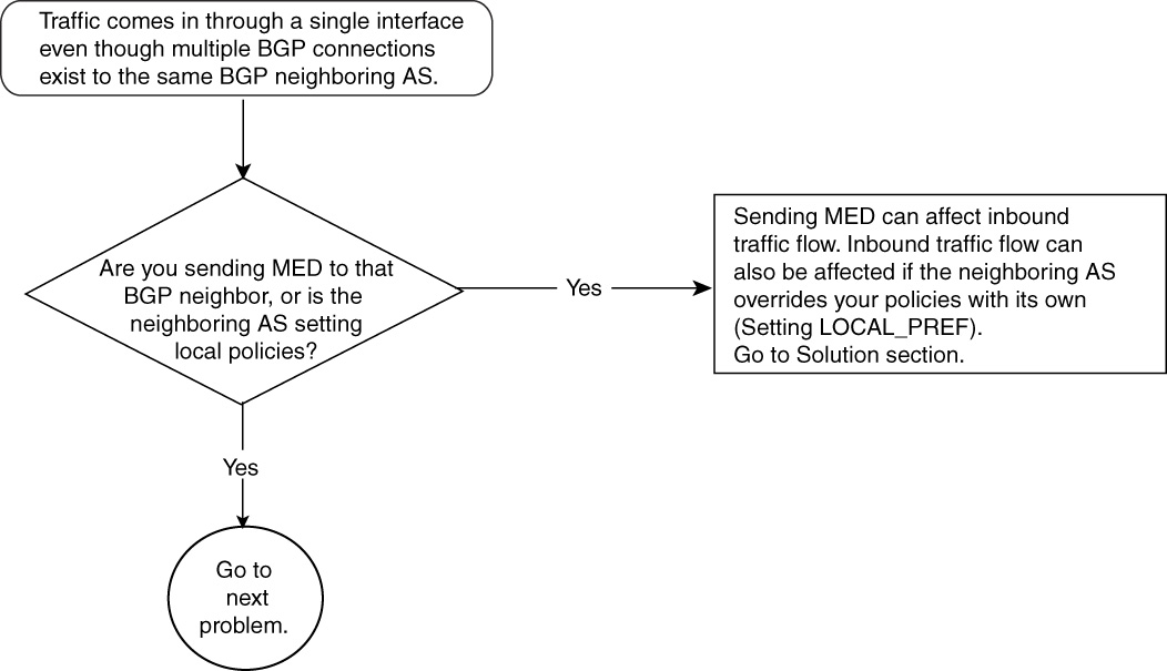
Figure 15-47 Problem-Resolution Flowchart
Debugs and Verification
This section discusses both cases of inbound traffic influence, discussed in the problem/cause presentation in the preceding section. Both necessary router configurations and show command outputs are displayed to examine the problem.
Case 1
This case is the one shown in Figure 15-45, in which R8 changed the LOCAL_PREFERENCE for 100.100.100.0/24. Example 15-87 shows the configuration in R8. The only significant con-figuration change is in R8, where route-map influencing_traffic is configured.
Example 15-87 R8 Configuration to Change LOCAL_PREFERENCE to Affect Best-Path Calculation of BGP
R8# router bgp 110
no synchronization
neighbor 172.16.28.2 remote-as 109
neighbor 172.16.28.2 route-map influencing_traffic in
neighbor 172.16.126.6 remote-as 110
!
access-list 1 permit 100.100.100.0
access-list 2 permit any
route-map influencing_traffic permit 10
match ip address 1
set local-preference 200
!
route-map influencing_traffic permit 20
match ip address 2
set local-preference 90
In Example 15-87, R8 is configured with route-map influencing_traffic sequence 10, which changes the LOCAL_PREFERENCE to 200 for prefix 100.100.100.0/24 permitted by access list 1. The highest LOCAL_PREFERENCE wins in BGP best-path calculation, which affects all IBGP speakers in AS 110 (R6, in this example) and makes the path from R8 the best exit point to reach 100.100.100.0/24. Sequence 20 of the route map influencing traffic changes the LOCAL_PREFERENCE attribute to 90 for all other routes learned from neighbor 172.16.28.2 (R2).
The output in Example 15-88 shows how BGP in R6 selects R8 as the best exit point. Notice that the first path (the best path) is an IBGP path from R6 to R8 with a LOCAL_PREFERENCE of 200. The second path is from the R1–R6 connection.
The output from R8 in Example 15-88 shows that it has only a path for 100.100.100.0/24 and that is from R2. LOCAL_PREFERENCE is shown as 200, making it a best path advertised to R6.
Example 15-88 show ip bgp Command Output Reveals the Best Exit Point
R6# show ip bgp 100.100.100.0
BGP routing table entry for 100.100.100.0/24, version 6
Paths: (2 available, best #1, table Default-IP-Routing-Table)
Advertised to non peer-group peers:
172.16.126.1
109
172.16.28.2 (metric 20) from 172.16.28.8 (172.16.8.8)
Origin IGP, metric 0, localpref 200, valid, internal, best
109
172.16.126.1 from 172.16.126.1 (172.16.1.1)
Origin IGP, metric 0, localpref 100, valid, external
R8#show ip bgp 100.100.100.0
BGP routing table entry for 100.100.100.0/24, version 2
Paths: (1 available, best #1, table Default-IP-Routing-Table)
Not advertised to any peer
109
172.16.28.2 from 172.16.28.2 (172.16.2.2)
Origin IGP, metric 0, localpref 200, valid, external, best
Case 2
This case is the one shown in Figure 15-46, in which R1 and R2 advertise different MEDs for 100.100.100.0/24 to R6 and R8, respectively.
Example 15-89 details the configuration needed in R1 and R2. R6 and R8 have the standard BGP configuration for a simple neighbor relationship, so it is not shown. R1 and R2 have route-map MED_advertisement that advertises MEDs to their EBGP neighbors R6 and R8, respectively.
Example 15-89 MED Advertisement from R1 and R2 to Influence Inbound Traffic for 100.100.100.0/24
R1# router bgp 109
no synchronization
bgp log-neighbor-changes
network 100.100.100.0 mask 255.255.255.0
network 200.100.100.0
neighbor 172.16.126.2 remote-as 109
neighbor 172.16.126.6 remote-as 110
neighbor 172.16.126.6 route-map MED_advertisement out
access-list 1 permit 100.100.100.0
access-list 2 permit any
!
route-map MED_advertisement permit 10
match ip address 1
set metric 20
!
route-map MED_advertisement permit 20
match ip address 2
set metric 100
R2# router bgp 109
no synchronization
network 100.100.100.0 mask 255.255.255.0
neighbor 172.16.28.8 remote-as 110
neighbor 172.16.28.8 route-map MED_advertisement out
neighbor 172.16.126.1 remote-as 109
!
!
access-list 1 permit 100.100.100.0
access-list 2 permit any
route-map MED_advertisement permit 10
match ip address 1
set metric 1
!
route-map MED_advertisement permit 20
match ip address 2
set metric 200
In Example 15-89, R1 and R2 have route-map MED_advertisement configured with neighbors R6 and R8, respectively. In the case of R1, sequence 10 of the route map sets MED of 20 for 100.100.100.0/24 by access list 1 and sets the rest of the prefix MED to 100 by sequence 20 of the route map.
R2 is configured in a similar manner to R1, but the MED of 1 is sent to R8 for 100.100.100.0/24 and a MED of 200 is sent for rest of the prefixes.
The output in Example 15-90 shows the BGP output of prefix 100.100.100.0/24. The MED value of 1 is learned from R2 at R8, making this route the best route in AS 110.
All traffic from AS 110 to prefix 100.100.100.0/24 will exit from X at R8. Notice the output in R6, which prefers the IBGP update from R8 because of a lower MED for prefix 100.100.100.0/24.
Example 15-90 BGP Output for Prefix 100.100.100.0/24 Reveals the Best Route
R8#show ip bgp 100.100.100.0
BGP routing table entry for 100.100.100.0/24, version 12
Paths: (1 available, best #1, table Default-IP-Routing-Table)
Advertised to non peer-group peers:
172.16.126.6
109
172.16.28.2 from 172.16.28.2 (172.16.2.2)
Origin IGP, metric 1, localpref 100, valid, external, best
R6#show ip bgp 100.100.100.0
BGP routing table entry for 100.100.100.0/24, version 13
Paths: (2 available, best #2, table Default-IP-Routing-Table)
Advertised to non peer-group peers:
172.16.126.1
109
172.16.126.1 from 172.16.126.1 (172.16.1.1)
Origin IGP, metric 20, localpref 100, valid, external
109
172.16.28.2 (metric 20) from 172.16.28.8 (172.16.8.8)
Origin IGP, metric 1, localpref 100, valid, internal, best
Solution
Return traffic influence can be desired as in Case 2, or it might happen as in Case 1. AS 109 BGP operators must understand what is causing this influence.
In Case 1, in which AS 110 changed its BGP policy by altering the LOCAL_PREFERENCE, BGP does not offer any commands for AS 109 to influence the AS 110 policy. Each AS can force its own policy, and the outside AS cannot change that. The solution for the Case 1 problem lies with the AS 109 administrator requesting AS 110 to remove any policy that affects AS 109.
In Case 2, AS 109 announced a MED and AS 110 was not configured to change LOCAL_PREFERENCE (as in Case 1).
If the MED announcement is not producing the desired behavior for AS 109 inbound traffic management, these MEDs should be removed, and the normal BGP policies of AS 110 should decide on the best entry into AS 109.
In larger BGP networks with numerous exit points and multiple BGP AS connections, traffic balance could become a challenge. Therefore, careful BGP policies and peering agreements must be created between BGP speakers, and traffic flow must be carefully observed.
Problem: Multiple Connections Exist to Several BGP Neighbors, but Most of the Traffic from Internet to 100.100.100.0/24 Always Comes in Through One BGP Neighbor from AS 110—Cause: Route Advertisements for 100.100.100.0/24 in AS 109 Attract Internet Traffic Through That BGP Neighbor in AS 110
When a BGP prefix is observed from a global Internet point-of-view, few BGP attributes stay intact from the originator of that prefix. For example, AS_PATH, ORIGIN_CODE and AGGREGATOR are the most common BGP attributes that get carried no matter how many autonomous systems a BGP update crosses. The most popular attributes, LOCAL_PREFERENCE and MED, do not cross an AS boundary. Therefore, they do not play any role in influencing return traffic from sources multiple autonomous systems away.
As discussed in Chapter 14, the most common BGP attributes that get used in the BGP best-path algorithm are LOCAL_PREFERENCE, AS_PATH and MED. Out of these, AS_PATH is the only attribute that stays intact from the originator of the prefix to any Internet BGP speaker.
Figure 15-48 shows the BGP update flow from AS 109 and also shows BGP best-path selection at each intermediate AS. AS 109 is originating AS 100.100.100.0/24, and its goal is to receive traffic from the Internet for 100.100.100.0/24 only through AS 110, not through AS 111.

Figure 15-48 BGP Update Flow from AS 109/Best-Path Selection at Intermediate Autonomous Systems
Solution
The following are two common practices that BGP administrators use to achieve the previously mentioned goal:
• AS 109 advertises network 100.100.100.0/24 with a much longer AS_PATH list to all BGP neighbors except AS 110. If autonomous systems 110, 112, and 113 do not make any additional changes in the BGP policy, autonomous systems 112 and 113 always go through AS 110 to reach 100.100.100.0/24.
This results in all traffic to network 100.100.100.0/24 entering AS 109 to traverse AS 110; the links between AS 109 and AS 111 for redundancy.
• AS 109 advertises 100.100.100.0/24 only to AS 110, not to BGP neighbor AS 111. Therefore, traffic from the Internet sees only one path to reach 100.100.100.0/24—through AS 110 to AS 109. However, this case loses redundancy if AS 109 loses its BGP session with AS 110.
Troubleshooting BGP Best-Path Calculation Issues
Chapter 14 discusses in detail how the BGP best-path algorithm works to select a single best route out of many to install in the IP routing table and to advertise to other BGP neighbors. This section discusses a few cases that deal with scenarios in which best-path selection does not work as intended.
The following are the cases discussed in this section:
• When the router ID (RID) selects the best path, BGP does not always select the lowest RID path as best, as described in the best-path algorithm.
• Two BGP neighbors in the same AS advertise a different MED for the same prefix, but the lowest MED is not selected as best, as described in the best-path algorithm.
Problem: Path with Lowest RID Is Not Chosen as Best
This is the scenario in which two or more paths from EBGP neighbors have identical BGP attributes and BGP best-path selection is done based on the RID. The BGP best-path selection rule states that, in case all other attributes are identical, the path with the lowest RID should be selected as best. In this case, the path with the highest RID is selected as best.
In Cisco IOS Software, if BGP selects a best path based on the RID and a new path comes in with a lower RID, with all other attributes being equal, the previously selected best path will not be toggled and will remain unchanged. This is done intentionally in Cisco IOS Software to maintain stability in BGP paths because newly selected paths must be advertised to all BGP neighbors, and the previous one must be withdrawn. To avoid this churn, BGP in Cisco IOS Software does not select a new best path if the previous path selected was done based on RID.
Figure 15-49 shows the flowchart to follow to resolve this problem.

Figure 15-49 Problem-Resolution Flowchart
Debugs and Verification
Figure 15-50 shows a network composed of R1 in AS 109, and R3 and R5 in AS 110. Both R3 and R5 are advertising 100.100.100.0/24. The RIDs of R3 and R5 are 3.3.3.3 and 5.5.5.5, respectively.

Figure 15-50 Network in Which Path with Lowest RID Is Not Chosen as Best
Example 15-91 shows the necessary configuration in R1, R3, and R5 to form a BGP neighbor relationship, and for R3 and R5 to advertise 100.100.100.0/24.
Example 15-91 Configuring R3 and R5 to Advertise 100.100.100.0/24 and to Form an EBGP Neighbor Relationship with R1
R1# router bgp 109
bgp router-id 1.1.1.1
neighbor 1.1.2.3 remote-as 110
neighbor 1.1.7.5 remote-as 110
R3# router bgp 110
bgp router-id 3.3.3.3
network 100.100.100.0 mask 255.255.255.0
neighbor 1.1.2.1 remote-as 109
neighbor 1.1.8.5 remote-as 110
R5# router bgp 110
bgp router-id 5.5.5.5
network 100.100.100.0 mask 255.255.255.0
neighbor 1.1.7.1 remote-as 109
neighbor 1.1.8.3 remote-as 110
The highlighted commands show how RID can be configured manually in BGP. Each router is configured with recognizable RIDs. This is done to ease in understanding BGP outputs later in this section.
Now, R1 will receive 100.100.100.0/24 from R3 and R5. The output in Example 15-92 shows that R1 is receiving both the updates and that it prefers the update from R5.
Example 15-92 BGP Output in R1 to Show the Best Path for 100.100.100.0/24
R1#show ip bgp 100.100.100.0
BGP routing table entry for 100.100.100.0/24, version 2
Paths: (2 available, best #2, table Default-IP-Routing-Table)
Advertised to non peer-group peers:
1.1.2.3
110
1.1.2.3 from 1.1.2.3 (3.3.3.3)
Origin IGP, metric 0, localpref 100, valid, external
110
1.1.7.5 from 1.1.7.5 (5.5.5.5)
Origin IGP, metric 0, localpref 100, valid, external, best
All BGP attributes (LOCAL_PREF, MED, ORIGIN CODE, and EXTERNAL versus INTERNAL) are identical. According to BGP best-path calculation rules, as described in Chapter 14, the best path should be the one with the lowest RID if all other attributes are identical. In this output, the path from RID 3.3.3.3 (R3) should have been the best, but the output in Example 15-92 shows that the best path is from 5.5.5.5 (R5).
To explain this problem, you must understand the sequence of events in R1. In R1, the path from R5 must have been received before the path from R3. If R1 has selected the path from R5 as best, when the path from R3 comes and the deciding factor for the best-path calculation is RID, R1 will keep R5 as the best even though R3 offered a lower RID.
Solution
If R1 wants the proper RID to be the deciding factor in best-path calculation, it must add a BGP knob in Cisco IOS Software, as shown in Example 15-93.
Example 15-93 BGP Knob to Compare RID in Best-Path Selection
R1# router bgp 109
bgp router-id 1.1.1.1
bgp bestpath compare-routerid
neighbor 1.1.2.3 remote-as 110
neighbor 1.1.7.5 remote-as 110
The highlighted command enables R1 to compare the RIDs of all the paths and pick the lowest RID as the best in BGP best-path calculation. The effect of this configuration change takes place when the BGP scanner runs. (It runs every minute in Cisco IOS Software.)
The output in Example 15-94 shows that R1 has selected the R3 path as best because the R3 path has a lower RID (3.3.3.3) than the R5 path (5.5.5.5).
Example 15-94 BGP Best-Path Selection Using RID
R1#show ip bgp 100.100.100.0
BGP routing table entry for 100.100.100.0/24, version 3
Paths: (2 available, best #1, table Default-IP-Routing-Table)
Advertised to non peer-group peers:
1.1.7.5
110
1.1.2.3 from 1.1.2.3 (3.3.3.3)
Origin IGP, metric 0, localpref 100, valid, external, best
110
1.1.7.5 from 1.1.7.5 (5.5.5.5)
Origin IGP, metric 0, localpref 100, valid, external
Problem: Lowest MED Not Selected as Best Path
In some scenarios, the router does not select the lowest MED advertised by neighbors as the best path.
Figure 15-51 shows a network setup that has AS 109 (R1) connected to AS 110 at two BGP peering points (R3 and R5); AS 109 has one connection with AS 111 (R4). R1 is receiving 100.100.100.0/24 from all three EBGP connections. All neighbors are advertising MEDs to influence return traffic from AS 109. R3 and R5 are advertising MEDs of 50 and 30, respectively, whereas R4 is sending a MED of 40.
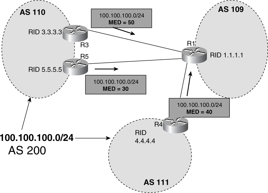
Figure 15-51 Network in Which Lowest MED Is Omitted from Selection of Best Path
R1 receives all three advertisements but failed to select the path from R5 (lowest MED) as the best path; instead, it selected the path from R3 (highest MED) as the best. This might cause traffic policy disturbance from the perspective of both AS 109 and AS 110 because the link between R1 and R3 could be smaller, and the link between R1 and R5 might be bigger; both autonomous systems want R1 and R5 to use for all traffic.
In Figure 15-51, both AS 109 and AS 110 expect that R1 will select the path from R5 as best because R5 clearly is advertising a MED of 30, as compared to a MED of 50 from R3. By BGP best-path calculation, the path from the lower MED should be selected as best. In addition, R4 is advertising 100.100.100.0/24 with a MED of 40.
One BGP rule that must be kept in mind is the rule of MED comparison. By default, Cisco IOS Software will not compare the MEDs if two paths came from different autonomous systems. R1 will ignore the MED when it is comparing the paths between R5 and R4. The tiebreaker in R1 to select a best path between R4 and R5 will be something other than the MED. If no other BGP attributes are used, the RID breaks the tie to select the best path. The “Debugs and Verification” section shows the sequence of events and output from the R1 BGP table to show that best path is indeed not the one that has the lowest MED (R5).
Figure 15-52 shows the flowchart to follow to resolve this problem.

Figure 15-52 Problem-Resolution Flowchart
Debugs and Verification
Example 15-95 shows the output from R1 for 100.100.100.0/24.
Example 15-95 Selection of Best Path, Ignoring Lowest MED
R1#show ip bgp 100.100.100.0
BGP routing table entry for 100.100.100.0/24, version 3
Paths: (3 available, best #1, table Default-IP-Routing-Table)
Advertised to non peer-group peers:
1.1.7.5 1.1.3.4
110 200
1.1.7.5 from 1.1.7.5 (5.5.5.5)
Origin IGP, metric 30, localpref 100, valid, external
111 200
1.1.3.4 from 1.1.3.4 (4.4.4.4)
Origin IGP, metric 40, localpref 100, valid, external
110 200
1.1.2.3 from 1.1.2.3 (3.3.3.3)
Origin IGP, metric 50, localpref 100, valid, external, best
The output in 15-95 shows that R1 has three paths in this order:
1 Path 1: This path is from R5 (RID 5.5.5.5), with a MED of 30.
2 Path 2: This path is from R4 (RID 4.4.4.4), with a MED of 40.
3 Path 3: This path is from R3 (RID 3.3.3.3) with a MED of 50.
If the best-path selection algorithm described in Chapter 14 were run, the following would be the selection process:
1 Path 1 is compared with Path 2. All BGP attributes are the same except for the MED. However, these two paths came from different autonomous systems—110 and 111, respectively—so the MED will not be the tiebreaker and will be ignored. The tiebreaker will be the RID. Based on the RID, path 2 has a lower RID (4.4.4.4) than path 1 (5.5.5.5). Therefore, path 2 is the winner.
2 The winner of Step 1, path 2, is compared with path 3. Again, the MED will be ignored because of a different AS_PATH. The lower RID of path 3 (3.3.3.3) will win again path 2’s RID (4.4.4.4).
Path 3 is selected as best even though it has a higher MED than any of the paths (MED 50).
Solution
To solve this problem, Cisco IOS Software must allow comparison of MEDs between different autonomous systems. Example 15-96 shows the configuration knob that can be added in R1 to achieve that.
Example 15-96 Knob to Compare MED from Different Autonomous Systems
R1#
router bgp 109
bgp router-id 1.1.1.1
bgp always-compare-med
neighbor 1.1.2.3 remote-as 110
neighbor 1.1.7.5 remote-as 110
neighbor 1.1.3.4 remote-as 111
The highlighted command enables R1 to compare MEDs in BGP best-path selection even though the paths came from different autonomous systems.
Example 15-97 shows the BGP table for 100.100.100.0/24 after the change.
Example 15-97 Desired BGP Path Selection After Comparing MEDs Between Different Autonomous Systems
R1#show ip bgp 100.100.100.0
BGP routing table entry for 100.100.100.0/24, version 3
Paths: (3 available, best #1, table Default-IP-Routing-Table)
Advertised to non peer-group peers:
1.1.3.4 1.1.2.3
110 200
1.1.7.5 from 1.1.7.5 ( 5.5.5.5 )
Origin IGP, metric 30, localpref 100, valid, external, best
111 200
1.1.3.4 from 1.1.3.4 ( 4.4.4.4 )
Origin IGP, metric 40, localpref 100, valid, external
110 200
1.1.2.3 from 1.1.2.3 ( 3.3.3.3 )
Origin IGP, metric 50, localpref 100, valid, external
The best path is the one that has the lowest MED. As stated earlier, choosing the path with the lowest MED could be crucial if links between autonomous systems are of different bandwidth and a path from a higher-bandwidth neighbor is sending a lower MED.
In addition, one important design recommendation is that the command bgp always-compare-med should be enabled on all the routes in an AS running BGP; otherwise, packet forwarding loops might occur. For example, Router A running this command might point its best path to Router B, whereas Router B without this command might point the best path back to Router A, resulting in a routing loop.
Troubleshooting BGP Filtering
BGP offers a powerful filtering mechanism when advertising or receiving BGP routes. Filtering rules are defined based on the BGP peering relationship. An ISP might want to exchange full BGP routes to another ISP but might want to give only partial routes to its enterprise customer. On the other hand, an enterprise customer might want to advertise IP blocks that run in its network only to its provider (say, ISP 1) and might want to filter advertisements from all other Internet routes received from another provider (say, ISP 2). Such requirement easily might be met by using powerful filtering options available in Cisco BGP, which can use access-list filters (both standard and extended), AS_PATH filtering, community filtering, and prefix-list filtering. All of these filtering methods can be applied modularly through Cisco IOS Software route maps on a per-neighbor basis or directly to the neighbors. The only exception is community-based filtering, which can be applied only through the route map. This section discusses issues related to access-list, prefix-list, and AS_PATH–based filtering.
Problem: Standard Access List Fails to Capture Subnets
In IP networks, IP prefixes are sliced in different subnets, and the subnet mask carried in the routing table does identification of these subnets. The current Internet BGP table has many IP prefixes with identical network numbers but different masks. Example 15-98 shows such an example in which R4 has three different masked prefixes of 13.13.0.0. To illustrate this point, static routes are created in R4, as shown by output in Example 15-98. Furthermore, these static routes are advertised in BGP by the highlighted redistribute static command.
Example 15-98 Three Different Masked Static Routes of Same Network and Their Advertisement in BGP
R4#show ip route static
13.0.0.0/8 is variably subnetted, 3 subnets, 3 masks
S 13.13.0.0/20 is directly connected, Serial 0
S 13.13.0.0/16 is directly connected, Serial 1
S 13.13.1.0/24 is directly connected, Serial 2
R4# router bgp 2
redistribute static
neighbor 131.108.1.1 remote-as 1
no auto-summary
R1 is an EBGP neighbor of R4. R1’s goal is to receive only 13.13.0.0/16 and to filter any more specific routes of 13.13.0.0. Typically, R1 would use some sort of filtering to block these unwanted, more specific routes. Distribute lists are used commonly to block or allow paths in BGP. A BGP operator might use a standard or extended access list in concert with distribute lists. Standard access list do not allow filtering based on the subnet mask of the route, and this is the most common mistake that BGP operators do when applying standard access lists in distribute lists. Chapter 14 describes in some detail the difference between standard and extended access lists when used with distribute lists or in route maps.
Figure 15-53 shows the flowchart to follow to resolve this problem.
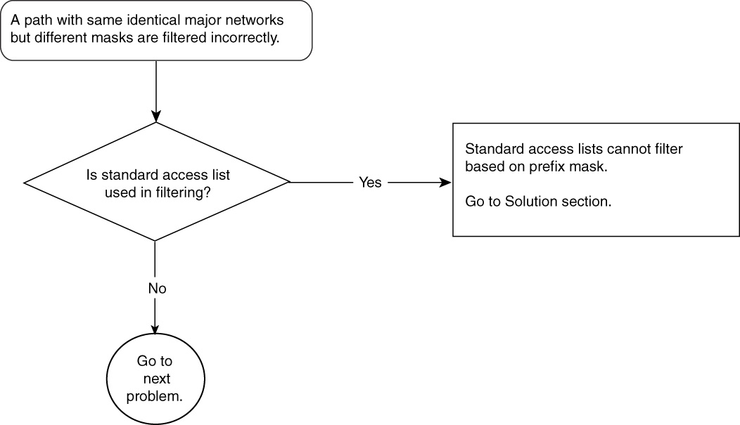
Figure 15-53 Problem-Resolution Flowchart
Debugs and Verification
Example 15-99 shows the BGP configuration of R1, with neighbor relationships and the distribute-list command using access list 1.
Example 15-99 BGP Configuration in R1 Using Standard Access List in distribute-list Command
R1# router bgp 1
neighbor 131.108.1.2 remote-as 2
neighbor 131.108.1.2 distribute-list 1 in
access-list 1 permit 13.13.0.0 0.0.255.255
distribute-list 1 means that any BGP updates that come from 131.108.1.2 will be examined by access list 1.
Access list 1 has a permit statement for 13.13.0.0 with an exact match of the first two octets (13.13); it doesn’t care about the last two octets (0.0).
Standard access list 1 has no mention of a mask of 13.13.0.0, so all masks are accepted. The output in Example 15-100 shows that the BGP table in R1 is receiving all three masks of 13.13.0.0.
Example 15-100 Mask of BGP Update Is Ignored When a Distribute List Uses a Standard Access List
R1# show ip bgp
BGP table version is 5, local router ID is 141.108.13.1
Status codes: s suppressed, d damped, h history, * valid, > best, i - internal
Origin codes: i - IGP, e - EGP, ? - incomplete
Network Next Hop Metric LocPrf Weight Path
*> 13.13.0.0/20 131.108.1.2 0 0 2 ?
*> 13.13.0.0/16 131.108.1.2 0 0 2 ?
*> 13.13.1.0/24 131.108.1.2 0 0 2 ?
Solution
Use extended access lists or prefix lists that support proper mask check of routes when received in BGP. Example 15-101 shows usage of extended access list 101, which checks not only the network number (13.13.0.0) but also the mask of the update.
Example 15-101 Extended Access List Checks the Subnet Mask of the Prefix
R1# router bgp 1
neighbor 131.108.1.2 remote-as 2
neighbor 131.108.1.2 distribute-list 101 in
access-list 101 permit ip 13.13.0.0 0.0.255.255 255.255.0.0 0.0.0.0
The extended access list has two parts:
• The network part—13.13.0.0 0.0.255.255, which allows 13.13.x.x, where x can any number between 0 and 255.
• The mask part—255.255.0.0 0.0.0.0. With all 0s in wildcard, the mask can only be 255.255.0.0, meaning /16.
The output in Example 15-102 shows that R1 is receiving only 13.13.0.0/16 after applying this change.
Example 15-102 Confirming Extended Access List Filters Routes Successfully
R1 #show ip bgp
BGP table version is 5, local router ID is 141.108.13.1
Status codes: s suppressed, d damped, h history, * valid, > best, i - internal
Origin codes: i - IGP, e - EGP, ? - incomplete
Network Next Hop Metric LocPrf Weight Path
*> 13.13.0.0/16 131.108.1.2 0 0 2 ?
Problem: Extended Access Lists Fails to Capture the Correct Masked Route
To reduce the size of Internet BGP/routing tables, BGP operators are forced to advertise aggregated prefixes and suppress subnetted IP blocks. To achieve this, almost all ISPs expect their peering ISPs and customers to advertise aggregated blocks of, say, /21 (255.255.248.0) of IP blocks and will refuse to accept any prefix with a mask greater than /21. Proper BGP filtering must be in place at peering points so that prefixes with masks greater than /21 can be filtered out and only prefixes with masks less than /21 are accepted.
Many times, use of extended access lists is not understood properly, resulting in failure to capture subnetted prefixes with masks greater than /21, for example.
Figure 15-54 shows a simple two-ISP network running EBGP. ISP AS 109 is supposed to be advertising only three prefixes to ISP 2 AS 110. The expected prefixes are 100.100.100.0/21, 99.99.99.0/21, and 89.89.89.0/21. However, AS 109 has subdivided these IP blocks into smaller subnets, to assign them internally in the network.
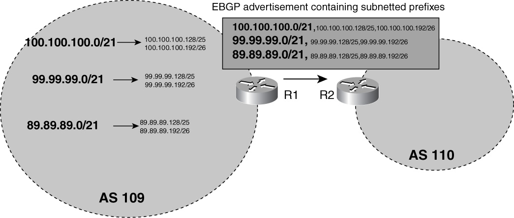
Figure 15-54 Two-ISP Network Running EBGP
Mistakenly, AS 109 is advertising all the tiny subnets to AS 110, resulting in its unnecessary increase in BGP and IP routing table size. This problem has two causes:
• AS 109 should filter subnets and advertise only the aggregated three prefixes.
• AS 110 should filter subnets and accept only the aggregated three prefixes.
Figure 15-55 shows the flowchart to follow to resolve this problem.

Figure 15-55 Problem-Resolution Flowchart
Debugs and Verification
Example 15-103 shows R1’s configuration to define static routes for subnetted blocks and BGP configuration to advertise these subnetted blocks to R2.
Example 15-103 Configuration in R1 to Create and Advertise Smaller Subnet Routes to R2
R1# ip route 100.100.100.0 255.255.248.0 Null0
ip route 100.100.100.128 255.255.255.128 serial 0
ip route 100.100.100.192 255.255.255.192 serial 1
ip route 99.99.99.0 255.255.248.0 Null 0
ip route 99.99.99.128 255.255.255.128 serial 2
ip route 99.99.99.192 255.255.255.192 serial 3
ip route 89.89.89.0 255.255.248.0 Null 0
ip route 89.89.89.128 255.255.255.128 serial 4
ip route 89.89.89.192 255.255.255.192 serial 5
router bgp 109
neighbor 131.108.1.2 remote-as 110
redistribute static
no auto-summary
The redistribute static command redistributes these subnets in BGP and advertises to only neighbor R2 (131.108.1.2) in AS 110.
Example 15-104 shows R2 receiving all the subnets in its BGP table.
Example 15-104 R2 BGP Table Shows All Subnets Received
R2# show ip bgp
BGP table version is 5, local router ID is 141.108.13.2
Status codes: s suppressed, d damped, h history, * valid, > best, i - internal
Origin codes: i - IGP, e - EGP, ? - incomplete
Network Next Hop Metric LocPrf Weight Path
*> 100.100.100.0/21 131.108.1.1 0 0 109 ?
*> 100.100.100.128/25 131.108.1.1 0 0 109 ?
*> 100.100.100.192/26 131.108.1.1 0 0 109 ?
*> 99.99.99.0/21 131.108.1.1 0 0 109 ?
*> 99.99.99.128/25 131.108.1.1 0 0 109 ?
*> 99.99.99.192/26 131.108.1.1 0 0 109 ?
*> 89.89.89.0/21 131.108.1.1 0 0 109 ?
*> 89.89.89.128/25 131.108.1.1 0 0 109 ?
*> 89.89.89.192/26 131.108.1.1 0 0 109 ?
The highlighted prefixes are the only prefixes that should have been accepted by R2. Moreover, those are only prefixes that R1 should have advertised to R2.
Solution
To solve this problem, either R1 should advertise only the /21s and block all the higher-mask prefixes, or R2 should block higher-mask prefixes and accept only /21s. This section discusses two methods to address this problem. Both solutions are generic enough for R1 and R2 to apply. If R1 uses the solution, it must apply the configuration on the outbound policy for R2; if R2 is applying the change, it must apply it as an inbound policy to R1.
The two solutions are as follows:
• Use an extended access list.
• Use a prefix list.
Extended Access List Solution
A generic filter needs to be created that can apply to any IP network but that has a tight filter for the mask of the prefix. With BGP filtering, you would use the following extended access list:
access-list 101 permit ip NETWORK WILD-CARD MASK WILD-CARD
A WILD-CARD of 0 means an exact match, whereas a WILD-CARD of 1 means “don’t care.”
An extended access list that would permit any IP network whose mask is /21 or lower (20, 19, and so on) is configured as follows:
access-list 101 permit ip 0.0.0.0 255.255.255.255 255.255.248.0 255.255.248.0
0.0.0.0 255.255.255.255 means any IP network.
255.255.248.0 255.255.248.0 means that a mask of this prefix can be only /21 or lower (/20, /19, and so on). Cisco IOS Software has an implicit deny at the end of each access list, so all prefixes whose masks are greater than 21 are denied.
Examples 15-105 and 15-106 demonstrate two methods in which access list 101 can be applied in R1.
Example 15-105 Applying Access List 101 with the distribute-list Command to the Neighbor
R1#
router bgp 109
neighbor 131.108.1.2 remote-as 110
neighbor 131.108.1.2 distribute-list 101 out
Example 15-106 Applying Access List 101 with the route-map Command to the Neighbor
router bgp 109
neighbor 131.108.1.2 remote-as 110
neighbor 131.108.1.2 route-map FILTERING out
route-map FILTERING permit 10
match ip address 101
Both commands have the same effect of blocking the advertisement of any prefix with a mask greater than /21.
Examples 15-107 and 15-108 demonstrate two methods in which access list 101 can be applied in R2.
Example 15-107 Applying Access List 101 with the distribute-list Command to the Neighbor
R2#
router bgp 110
neighbor 131.108.1.1 remote-as 109
neighbor 131.108.1.1 distribute-list 101 in
Example 15-108 Applying Access List 101 with the route-map Command to the Neighbor
R2#
router bgp 110
neighbor 131.108.1.1 remote-as 109
neighbor 131.108.1.1 route-map FILTERING in
route-map FILTERING permit 10
match ip address 101
Both commands have the same effect of blocking any prefix with a mask greater than /21.
Apart from distribute lists, prefix lists can be used to achieve the same goal.
You can apply the following prefix list to R1 and R2 in a similar fashion as a distribute list with both the neighbor statement and with a route map:
ip prefix-list FILTERING seq 5 permit 0.0.0.0/0 le 21
0.0.0.0 means any prefix, and /0 le 21 means that the mask of any prefix could be from 0 and less than or equal (le) to 21. All other higher-masked prefixes (/22, /25, /26, and so on) will be denied because of an implicit deny at the end of each Cisco IOS Software filter.
After applying the distribute list or prefix list in R1 or R2, Example 15-109 shows that the output of the BGP table in R2 is reduced to receiving just /21 prefixes.
Example 15-109 Proper Filtering Resulted in Reduction in BGP Table Size
R2 #show ip bgp
BGP table version is 5, local router ID is 141.108.13.2
Status codes: s suppressed, d damped, h history, * valid, > best, i - internal
Origin codes: i - IGP, e - EGP, ? - incomplete
Network Next Hop Metric LocPrf Weight Path
*> 100.100.100.0/21 131.108.1.1 0 0 109 ?
*> 99.99.99.0/21 131.108.1.1 0 0 109 ?
*> 89.89.89.0/21 131.108.1.1 0 0 109 ?
The distribute list and prefix list take effect when updates come from a neighbor. If BGP updates already have been received, applying the distribute list or prefix list will have no effect. To receive updates from neighbors, routers must restart the BGP session by using the commands clear ip bgp neighbor or clear ip bgp neighbor soft in, if soft reconfiguration is enabled. Refer to the Cisco IOS Software manual for more details on this command. A recent feature of Cisco IOS Software called route refresh automatically requests fresher updates from a neighbor when any policy, such as a distribute list or a prefix list, gets applied. This feature does not require clearing of the current BGP session.
Problem: AS_PATH Filtering Using Regular Expressions
All BGP updates that contain an announcement of IP prefixes have an AS_PATH field that lists all the autonomous systems that this update has traversed. BGP operators use filtering against this AS_PATH field to allow or deny IP prefixes and also to apply BGP policy based on AS_PATH filtering. This method offers greater flexibility in applying just a single line of filtering and not listing all IP prefixes, as in the case of distribute lists or prefix lists.
Commonly seen problems are mostly the result of a lack of understanding of UNIX-like BGP regular expressions. Chapter 14 sections on AS_PATH cover the most commonly used regular expression in AS_PATH filtering in Cisco.
Summary
Troubleshooting BGP problems should be addressed by keeping the OSI model in perspective. For example, if a BGP neighbor relationship is having a problem, physical connectivity to the neighbor should be examined before looking at TCP packets carrying BGP information.
The configuration to operate BGP in Cisco IOS Software is fairly static and simple, but the dynamics behind these simple configuration commands are fairly complex. Therefore, BGP standards as described in RFCs must be understood well before operating BGP in large IP networks. Operators of a BGP network must understand the proper use of Cisco IOS Software configuration commands. Any minor mistake can cause serious problems not only in an operator’s own network, but also to peering networks as well. These problems even can cascade into a worldwide BGP problem. For example, bogus static routes can be created for testing purposes in a router that has redistribute static configured in BGP configuration without any filters. This would result in accidentally announcing those bogus static routes to all BGP peers, which would further forward those bogus routes to their BGP peers. This would result in worldwide BGP announcement of fake routes and might wreak havoc in BGP networks. The dynamics behind the static configuration must be understood to troubleshoot problems in BGP.
Commonly, BGP operators face challenges in managing IP traffic flows coming in and going out of their IP networks running BGP. To obtain optimal utilization of network, BGP operators must understand how to use BGP to influence their desired traffic patterns in the network. Typically, tweaking BGP attributes such as LOCAL_PREFERENCE, AS_PATH, MED, and ORIGIN_CODE does this. Therefore, BGP network operators must master these attributes.
Problems might result from the configuration of BGP attributes or how BGP uses these attributes to compute the BGP best path from many paths to forward IP traffic. If proper preference of each attribute is not understood correctly, BGP operators might never influence traffic in their network correctly.
All sorts of problems come in different protocols for a variety of reasons, but a clear and logical approach should be taken to address those problems. This requires solid understanding of the protocols and an awareness of best-practice troubleshooting techniques. This book tries to offer fundamentals of each IP protocol and to provide enhanced troubleshooting techniques as seen in real-world IP networks.