Chapter 11. Troubleshooting IS-IS
This chapter covers the following key topics:
• Troubleshooting of IS-IS adjacency problems
• Troubleshooting of IS-IS routing update problems
• Case study: ISDN configuration problem
Chapter 10, “Understanding Intermediate System-to-Intermediate System (IS-IS),” provides an overview of the IS-IS routing protocol, covering IS-IS protocol concepts and basic con-figuration on Cisco routers. In line with the overall theme of this book, this chapter covers troubleshooting of IS-IS routing problems. Cisco routers and IOS Software provide the framework for the ensuing discussions, which focus on only IP-related issues. Two main categories of IS-IS routing problems exist:
• Misconfiguration and interoperability problems
• Problems caused by malfunctioning of software or hardware
In the absence of any obvious misconfiguration or interoperability issues, any operational issues most likely would be the result of malfunctioning hardware or software bugs. In most such cases, this can be discerned after confirming the configuration is okay or the problem seems to be limited to a particular interface. Problems caused by hardware- and software-related bugs are beyond the scope of this chapter and are not discussed further. Any such problems should be referred to the Cisco Technical Assistance Center for further diagnosis. The discussions in this chapter largely focus on troubleshooting problems caused by misconfiguration, interoperability, or inadequate network resource issues. Network resource issues are triggered when some or all of the routers in the network are low on CPU or memory resources required for storing and computing large amounts of routing information.
In general, however, IS-IS seems relatively easier to troubleshoot when compared to similarly complex routing protocols, such as OSPF. A major contributing factor to this is that IS-IS routers advertise routing information consolidated usually in single LSPs, which are easy to track throughout the network. LSPs can be fragmented, if necessary, but this is rare in today’s large IS-IS domains that connect to the Internet. In contrast, OSPF, for example, uses multiple LSA types for carrying different kinds of link-state information. The multiple individual LSAs advertised by each router create a complex environment tracking routing information and troubleshooting problems.
Another reason is that IS-IS has been deployed in some of the largest service-provider networks, even though in single-area topologies, for reasonably long enough to enable the Cisco implementation to be mature and stable. Additionally, inherent attributes of the IS-IS protocol allow for deployment in a large, flat network design with remarkable stability. In contrast, OSPF requires hierarchical deployment in large networks, for constraining areas into manageable sizes. In general, hierarchy is necessary for scaling any network, yet it undoubtedly introduces sophistication into the design, which, in turn, complicates troubleshooting.
In summary, it is significantly easier to troubleshoot a large, flat IS-IS network by tracking a single LSP for each router than it is to track multiple OSPF LSAs for each router in a hierarchical topology. This foregoing observation is not intended to pitch one protocol against the other. For the most part, IS-IS and OSPF are identical in functionality and demonstrate similar capabilities in a well-designed network.
Probably the most challenging thing about IS-IS for the newly initiated is having to deal with two independent addressing schemes—IP addressing and ISO CLNP addressing. In most cases, there is less familiarity with CLNP addresses, which are also known as NSAPs. The rather long NSAP addresses (up to 160 bits) can be daunting for many who are less exposed to them. On the other hand, IP addresses have a maximum size of 32 bits, with another 32 bits for the mask. CLNP addressing is covered as part of the introduction to IS-IS in Chapter 10. As pointed out in that chapter, even though IS-IS is used for IP routing, it operates within the framework of the ISO connectionless network protocol requiring the need for NSAPs to be configured on routers for node identification. As already indicated, Integrated IS-IS can be used for routing CLNP and IP simultaneously. In general, CLNP addressing is not as complicated as it might seem. Understanding the structure of NSAPs should help alleviate any potential discomfort working with them. Additionally, familiarity with the NSAP format can provide significant advantages in troubleshooting some IS-IS problems—in particular, adjacency-formation problems.
Because of the complicity of CLNP in the IS-IS framework, you must be familiar with CLNP-specific show commands as well as IS-IS-specific commands, in addition to the generic IP commands for troubleshooting routing problems. Cisco IOS Software also features debugging commands for CLNP and IS-IS that you should become familiar with. As you might recall, CLNP is the Layer 3 protocol within the ISO connectionless network services (CLNS) framework. For historical reasons, the keyword clns is used in place of the more appropriate clnp in CLNP-related commands. This misnomer, however, has been retained in the Cisco IOS command line interface (CLI) for backward compatibility.
The following key show commands commonly are used for troubleshooting IS-IS routing problems:
• show clns neighbors—Verifies the status of adjacencies
• show clns interface—Verifies configuration of an active CLNS interface
• show isis database—Lists LSPs in the link-state database
• show isis topology—Lists the system IDs of known IS-IS routers
• show isis spf-log—Displays logged SPF-related events
The following IS-IS debugging commands provide useful output and frequently are used in addition to show commands for troubleshooting complicated problems:
• debug isis adj-packets
• debug isis update-packets
• debug isis spf-events
Unlike the show and debug commands, which are used reactively for troubleshooting problems, the log-adjacency-changes command, which is an IOS router-level configuration command, proactively enables logging of IS-IS adjacency changes. Any such logged information can be an indication of flaky links and potential connectivity problems.
Sometimes, a simple reset of IS-IS–related data structures with the command clear isis * can help save the day. In this case, the problem obviously might be caused by buggy code. Infrequently, a network operator could get temporary relief from a problem by restarting the IS-IS process—that is, removing the IS-IS router configuration and re-entering it. Problems resolved that way are the result of bugs and would always come back to haunt you.
You might run into many problems that are caused by misconfiguration and malfunction of software and hardware. This chapter covers the following generic problem categories in detail and elaborates on the steps needed to troubleshoot them:
• IS-IS adjacency problems
• Route advertisement problems
• Route installation problems
• Route redistribution and summarization problems
• Route flaps
• IS-IS error messages
• Interoperability issues
The rest of the chapter tackles these problems.
Troubleshooting IS-IS Adjacency Problems
IS-IS adjacency-related problems normally are caused by link failures and configuration errors. On Cisco routers, link failures easily can be identified by inspection of a show interface command output. Also, because IS-IS routing is not required to establish IP connectivity to directly attached routers, it is easy to discern whether the problem is media-related or specific to the IS-IS configuration.
The show clns neighbors command is usually the starting point for troubleshooting IS-IS adjacency problems. Chapter 10 provides a preview of this command in the coverage of basic configuration and verification of IS-IS operation. The output of this command should list all neighbors expected to be adjacent to the router being investigated. The command show clns is-neighbors provides similar output, but it is intended to list only neighbor routers or IS-IS adjacencies; the previous command lists all types of adjacencies, both for IS-IS and for ES-IS.
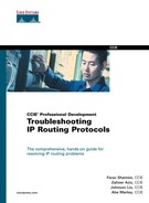
Before proceeding with the troubleshooting scenarios, take a look at this command again. The output in Example 11-1 was obtained from RT1, which is connected, as shown in Figure 11-1. Also shown in Example 11-1 is a variation of this command with an additional keyword, detail.

Figure 11-1 Network Diagram for Example 11-1
Example 11-1 show clns neighbors Command Output
RT1#show clns neighbors
System Id Interface SNPA State Holdtime Type Protocol
RT2 Se0/0 *HDLC* Up 27 L2 IS-IS
RT5 Et0/0 00d0.58eb.ff01 Up 25 L1 IS-IS
RT1#show clns neighbors detail
System Id Interface SNPA State Holdtime Type Protocol
RT2 Se0/0 *HDLC* Up 24 L2 IS-IS
Area Address(es): 49.0002
IP Address(es): 192.168.1.2*
Uptime: 02:15:11
RT5 Et0/0 00d0.58eb.ff01 Up 23 L1 IS-IS
Area Address(es): 49.0001
IP Address(es): 10.1.1.5*
Uptime: 02:15:11
The show clns neighbors command provides a summary of known neighbors, the connecting interface, and the state of the adjacency. The show clns neighbors detail command provides more information about each neighbor, such as the area that it belongs to and how long it has been known (uptime). Explanation of the fields in this output is as follows:
• System ID—System identifier of the neighbor.
• Interface—Physical interface where the neighbor is connected.
• SNPA—Subnetwork point of attachment. This is the data link type or address (HDLC or PPP for serial, and MAC address for LANs).
• State—State of the adjacency—up, down, or init.
• Holdtime—The time interval until expiration of the adjacency. The holdtime is reset to the product of the hello interval and hello multiplier for corresponding neighbors every time that a hello is received from them. The default values of the hello interval and the hello multiplier are 10 seconds and 3, respectively; hence, the holdtime is reset to 30 seconds on receipt of a hello packet under default conditions of operation.
• Type—Type of adjacency—Level 1, Level 2, or both.
• Protocol—The type of adjacency—IS-IS, ISO IGRP, or ES-IS.
Problems with IS-IS adjacency formation can be registered by the presence of fewer neighbors than are expected or a situation in which the status of an expected adjacency is not up. Another symptom could be that the neighbor is known through the ES-IS protocol instead of IS-IS.
You might recall from Chapter 10 that the ES-IS protocol is one of three protocols that supports the ISO CLNS environment. All ISO devices run the ES-IS protocol to facilitate mutual discovery and communication between end systems and routers in the CLNS environment. End systems and routers exchange end-system hellos (ESHs) and intermediate-system hellos (ISHs) within the ES-IS framework. Connected routers also receive each other’s ISHs and form ES-IS adjacencies. Therefore, it is possible that ES-IS adjacencies might still be formed between two routers even if there are problems with the IS-IS adjacency.
In the output of show clns displayed in Example 11-1, RT1 has properly formed adjacencies with its directly connected neighbors, RT2 (over Serial 0/0) and RT5 (over Ethernet 0/0). By using a three-way handshake to complete the adjacency process, RT1 can be certain that both RT2 and RT5 also have normally established corresponding adjacencies in the reverse direction. Example 11-2 shows similar output from RT1 featuring problems with the adjacencies formed with RT2 and RT5.
Example 11-2 show clns neighbors Command Output
RT1#show clns neighbors
System Id Interface SNPA State Holdtime Type Protocol
RT2 Se0/0 *HDLC* Init 27 L2 IS-IS
RT5 Et0/0 00d0.58eb.ff01 Up 25 L1 ES-IS
In this example, the IS-IS adjacency with RT2 is in INIT state instead of UP. The protocol is correctly shown as IS-IS. However, the adjacency with RT5 is in UP state; however, the protocol is ES-IS instead of IS-IS. As explained previously, the ES-IS protocol runs independently of IS-IS; therefore, the ES-IS adjacency formed between RT1 and RT5 has nothing to do with IS-IS. These routers cannot form an IS-IS adjacency with each other, apparently because of a problem in the configuration or the IS-IS environment. When you determine that an IS-IS adjacency problem is not the result of link problems, you can use the show clns interface command to display anomalies, such as contention over the role of designated intermediate system (DIS). Most adjacency problems related to the IS-IS environment can be debugged with the debug isis adj-packets command. The output of this command can be daunting if the router under inspection has many neighbors because the display shows all the hellos transmitted and received by the local routers. Consecutive hellos sent and received between two stations are spaced at approximately 10 seconds, in the default setting, so information fills the screen quickly.
The objective of the sections that follow is to assist you in understanding the nature of adjacency problems, uncover the causes, and correct them. Networks are critical in today’s business environment, and the ability to troubleshoot problems quickly is a virtue that helps save businesses from the high costs associated with network outages and earns the network operator years of employability and accompanying benefits.
The following sections discuss adjacency problems and suggest possible causes.
Table 11-1 summarizes the adjacency problems and possible causes covered in this section. This abbreviated representation is designed to facilitate reference to the material. Each problem listed is subsequently elaborated, and pointers are provided on how to identify the symptoms and the necessary actions required to correct a specific problem.
Table 11-1 IS-IS Adjacency Problems/Causes

Problem 1: Some or All of the Adjacencies Are Not Coming Up
The absence of some expected IS-IS adjacencies means that the affected routers will not be capable of exchanging routing information, effectively creating reachability problems to certain destinations in the network.
Figure 11-2 shows a simple network in which four daisy-chained routers are grouped in twos and placed in separate areas.

Figure 11-2 Simple Network Diagram for Illustrating Adjacency Problems
The output of the show clns neighbors command captured on RT1 and shown in Example 11-3 displays only one neighbor instead of the expected two. RT2 is listed, but RT5 is missing. Because RT5 also is expected to be adjacent, this signals an adjacency problem that needs to be further investigated.
Example 11-3 show clns neighbors Command Output Reveals a Missing Neighbor
RT1#show clns neighbors
System Id Interface SNPA State Holdtime Type Protocol
RT2 Se0/0 *HDLC* UP 27 L2 IS-IS
The flowchart in Figure 11-3 illustrates the logical steps for troubleshooting the problem. These steps also are elaborated in the text that follows.

Figure 11-3 Flowchart for Resolving Missing IS-IS Adjacencies
Step 1: Checking for Link Failures
The first step toward addressing this problem is to make sure that all the interfaces on which adjacencies should be formed are in the up/up state. On Cisco routers, this can be done quickly with the show ip interfaces brief command, which displays a summary of all the interfaces, as shown in Example 11-4. The example is based on Figure 11-2.
Example 11-4 show ip interfaces brief Command Output Displays Physical State of Interfaces
RT1#show ip interface brief
Interface IP-Address OK? Method Status Protocol
Ethernet0/0 10.1.1.1 YES NVRAM administratively down down
Serial0/0 192.168.1.1 YES NVRAM up up
FastEthernet1/0 unassigned YES unset administratively down down
Loopback0 11.1.1.1 YES NVRAM up up
The Status column of the show ip interfaces brief command tells whether an interface is up, down, or administratively down at the physical level. The Protocol column also needs to be up in order to confirm normal operation at the data link. Verify that the interface is working by pinging across to the other end, as demonstrated on Example 11-5. From Figure 11-2, you know that RT2 is on the other end of serial0/0 and has an IP address of 192.168.1.2 on the corresponding interface. Therefore, a ping to this interface will verify whether packets can go over the link. A successful ping test is confirmed by exclamations, as shown in Example 11-5. When the ping test fails, dots instead of exclamations are displayed. If the ping fails, the physical connectivity problem first must be resolved before IS-IS operation is checked any further.
Example 11-5 Using ping to verify connectivity
RT1#ping 192.168.1.2
Type escape sequence to abort.
Sending 5, 100-byte ICMP Echos to 192.168.1.2, timeout is 2 seconds:
!!!!!
Success rate is 100 percent (5/5), round-trip min/avg/max = 1/2/4 ms
Step 2: Verifying Basic Configuration
If the link is fine, the next step involves verifying the IS-IS configuration. In general, IS-IS is enabled in two steps. First, the IS-IS process is configured, as shown in Example 11-6. Make sure that the IS-IS process is defined and that an NSAP or NET is configured.
Example 11-6 IS-IS Process Configuration
router isis
net 49.0001.0000.0000.0001.00
Unlike other IP routing protocols, such as RIP and OSPF, the IS-IS configuration doesn’t use network statements to enable IS-IS routing on the router’s interfaces. For example, in OSPF, if the IP subnet configured on an interface falls in the range of a network statement, OSPF will send Hellos over that interface to form adjacencies and therefore exchange IP routing information over that interface.
To enable IS-IS routing for IP on a Cisco router, you must configure the ip router isis command on the appropriate interfaces. The IP subnets on interfaces enabled for IS-IS routing in this manner automatically are put into the locally generated LSP. The only network statement required in IS-IS is the ISO NSAP, which also commonly is referred to as the network entity title (NET). However, it should be noted that misconfigured NETs are a common cause of IS-IS adjacency problems. This is further described later in Step 4, “Checking for Area Misconfiguration.”
For interfaces on which the ip router isis command is missing, make sure that the router-level passive-interface command is not being used to disable IS-IS routing on them. When an interface is made passive, the ip router isis command automatically is removed from the interface. An interface is made passive if it is desirable to advertise its associated IP subnet without forming any adjacencies over it. Loopback interfaces normally are configured this way.
Step 3: Checking for Mismatched Level 1 and Level 2 Interfaces
IS-IS supports a two-level routing hierarchy in which routing within an area is designated as Level 1 and routing between areas is designated as Level 2. An IS-IS router can be configured to participate in Level 1 routing only (Level 1 router), Level 2 routing only (Level 2 router), or both (Level 1–2 router). Level 1–2 routers act as border routers between IS-IS areas and facilitate interarea communication.
In the default mode of operation, Cisco routers have Level 1–2 capability. Two directly connected routers with a common area ID will form a Level 1–2 adjacency by default, even though only a Level 1 adjacency is necessary for them to communicate. You can use the router-level is-type command to change this behavior.
Using Figure 11-2 as an example, it might be desirable to make RT5 a Level 1–only router while RT1 remains capable of Level 1–2. This requires RT5 to be configured with the is-type level-1 command, but nothing needs to be done on RT1. If RT1 is made a Level 2–only router with the command is-type level-2-only, it will not be capable of forming a Level 1 adjacency with RT5. As shown in Figure 11-2, the proper setup is to make RT5 a Level 1 router only if it has limited resources (memory and CPU capacity); RT1 should be a Level 1–2 router for it to communicate with RT5 at Level 1 and with RT2 at Level 2 because RT2 is in another area. Just as with RT5, RT6 can be a Level 1–only router, if necessary.
Step 4: Checking for Area Misconfiguration
In the CLNP addressing overview provided in Chapter 10, the three main components of an NSAP address are discussed. With 1 byte at the farthest right end of the NSAP reserved for the NSEL and the following 6 bytes for the system ID, the rest of the address defines the area ID (see Figure 10-8 in Chapter 10).
Just as in the case of Step 3, two routers in different areas with different area IDs consequently are assigned to different areas and, therefore, form only a Level 2 adjacency. Using Figure 11-2 as an example, if RT5 is configured as Level 1 only but its area ID is misconfigured to be different from the area ID of RT1, these two routers will not form any adjacency. The configuration in Example 11-7, even though RT1 is expected to be in area 49.0001, has been configured with an area ID of 49.0005 placing it in a different area from RT5. Therefore, RT5 must be Level 2–capable to form adjacencies with RT1. However, it has been made a Level 1–only router with the command is-type level-1. Therefore, no IS-IS adjacency will be formed between RT1 and RT5.
Example 11-7 RT1 and RT5 Configurations Show Area IDs and Adjacency Capabilities
hostname RT1
!
interface Ethernet 0/0
ip address 10.1.1.1 255.255.255.0
ip router isis
!
router isis
net 49.0001.0000.0000.0001.00
hostname RT5
!
interface Ethernet0/0
ip address 10.1.1.5 255.255.255.0
ip router isis
!
router isis
net 49.0005.0000.0000.0005.00
is-type level-1
Step 5: Checking for Misconfigured IP Subnets
In recent releases of Cisco IOS Software, particularly in 12.0S, 12.0ST, and 12.0T release trains, adjacencies will not be formed between two neighbors if their directly connected interfaces are not in the same IP subnet. In Example 11-8, the address of RT1 is changed to that of another subnet. Again using Figure 11-2 for illustration, Example 11-9 shows RT1 rejecting the hello received from RT5 because the interface address 10.1.1.5 advertised by the latter is not on subnet 10.1.8.0/24.
Example 11-8 Verifying the Effect of an IP Subnet Mismatch on IS-IS Adjacencies
RT1#show interface Ethernet 0/0
Ethernet0/0 is up, line protocol is up
Hardware is AmdP2, address is 00d0.58f7.8941 (bia 00d0.58f7.8941)
Internet address is 10.1.1.1/24
RT1#conf t
Enter configuration commands, one per line. End with CNTL/Z.
RT1(config)#int e 0/0
RT1(config-if)#ip address 10.1.8.1 255.255.255.0
RT1(config-if)#^Z
Example 11-9 Debugging Adjacency Problems Caused by an IP Subnet Mismatch
RT1#debug isis adj-packet
IS-IS Adjacency related packets debugging is on
Apr 21 21:55:39: ISIS-Adj: Rec L1 IIH from 00d0.58eb.ff01 (Ethernet0/0), cir ty7
Apr 21 21:55:39: ISIS-Adj: No usable IP interface addresses in LAN IIH from Eth0
Apr 21 21:55:40: ISIS-Adj: Sending L1 IIH on Ethernet0/0, length 1497
Apr 21 21:55:41: ISIS-Adj: Sending serial IIH on Serial0/0, length 1499
Apr 21 21:55:42: ISIS-Adj: Rec L1 IIH from 00d0.58eb.ff01 (Ethernet0/0), cir ty7
Apr 21 21:55:42: ISIS-Adj: No usable IP interface addresses in LAN IIH from Eth0
Apr 21 21:55:43: %CLNS-5-ADJCHANGE: ISIS: Adjacency to RT5 (Ethernet0/0) Down,
Apr 21 21:55:43: ISIS-Adj: L1 adj count 0
In earlier Cisco IOS Software releases, it did not matter whether the routers belonged to different IP subnets because IS-IS adjacency formation occurs primarily within the CLNP framework, where IP addresses are irrelevant. However, in IP applications, directly connected routers must be on the same subnet, except when IP unnumbered is used. Therefore, the recent behavior provides an extra check for the IP configuration while introducing sanity into IS-IS data structures for tracking IP information.
In summary, it is important to make sure that directly connected routers that need to form IS-IS adjacencies for IP routing are on the same IP subnet.
Step 6: Check for Duplicate System IDs
If the previous steps checked out okay but a specific neighbor is not in the show clns neighbor output, it is possible that adjacency is not being formed because that neighbor has a duplicate system ID with the local router. An IS-IS router will not form an adjacency with a router in the same area that has a duplicate system ID. It also logs a duplicate system ID error, as shown in Example 11-10. Use the show logging command to display entries in the log. If duplicate system ID errors are found, the source of the conflict can be determined from the output of debug adj-packets, which points to the interface where the hellos with the duplicate system ID are coming from. See Example 11-11.
Example 11-10 Duplicate System ID Error Logs
RT1#show logging
Apr 21 16:30:59: %CLNS-3-BADPACKET: ISIS: LAN L1 hello, Duplicate system ID det)
Apr 21 16:31:59: %CLNS-3-BADPACKET: ISIS: LAN L1 hello, Duplicate system ID det)
Apr 21 16:33:00: %CLNS-3-BADPACKET: ISIS: LAN L1 hello, Duplicate system ID det)
Example 11-11 Detecting Duplicate System IDs with debug isis adj-packet
RT1#debug isis adj-packet
IS-IS Adjacency related packets debugging is on
RT1#
Apr 21 21:43:08: ISIS-Adj: Sending L2 IIH on Ethernet0/0, length 1497
Apr 21 21:43:09: ISIS-Adj: Sending L1 IIH on Ethernet0/0, length 1497
Apr 21 21:43:09: ISIS-Adj: Rec L1 IIH from 00d0.58eb.ff01 (Ethernet0/0), cir ty7
Apr 21 21:43:09: ISIS-Adj: Duplicate system id
Apr 21 21:43:12: ISIS-Adj: Sending L1 IIH on Ethernet0/0, length 1497
Apr 21 21:43:12: ISIS-Adj: Sending L2 IIH on Ethernet0/0, length 1497
Apr 21 21:43:12: ISIS-Adj: Rec L1 IIH from 00d0.58eb.ff01 (Ethernet0/0), cir ty7
Apr 21 21:43:12: ISIS-Adj: Duplicate system id
Problem 2: Adjacency in INIT State
The most common causes for an adjacency getting stuck in INIT state are mismatched interface MTU and misconfigured authentication parameters. The output in Example 11-12 shows what an adjacency would look like when stuck in INIT.
Example 11-12 IS-IS Adjacency Stuck in an INIT State
RT2#show clns neighbors
System Id Interface SNPA State Holdtime Type Protocol
RT1 Se0/0 *HDLC* Init 29 L2 IS-IS
To guarantee that adjacent IS-IS routers can receive and process LSPs of manageable sizes from each other, ISO 10589 specifies that hellos, which are used to form and maintain adjacencies, should be padded up to maxsize – 1, where maxsize is the maximum LSP buffer size or the MTU of the outgoing interface of the source node. The objective of this requirement is to ensure that an adjacency will be formed only between routers capable of handling all IS-IS packets sent to each other. The maximum LSP buffer size is specified as 1492 bytes; however, Cisco IOS Software defaults to the MTU, meaning that hellos are padded to MTU – 1 bytes. Therefore for Cisco routers, everything being equal, adjacencies are formed only when MTUs of directly connected interfaces match.
Figure 11-4 illustrates a situation for normal adjacency formation.
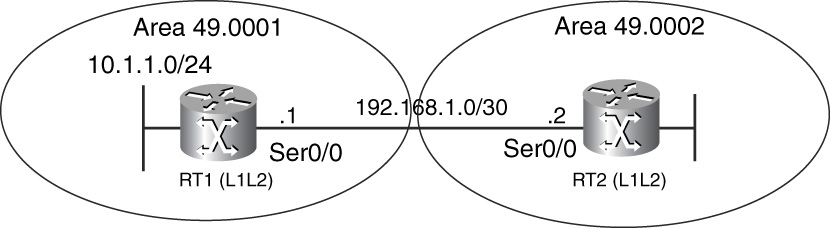
Figure 11-4 Investigating IS-IS Adjacencies—A Simple Network
In Example 11-13, the output of show clns neighbors from RT1 shows that the adjacency state is up and that the protocol type is IS-IS. Example 11-13 also shows excerpts of the show clns interface command from the two routers involved, RT1 and RT2. The MTU is 1500 bytes on either side.
Example 11-13 Correctly Formed IS-IS Adjacency
RT1#show clns neighbors
System Id Interface SNPA State Holdtime Type Protocol
RT2 Se0/0 *HDLC* Up 250 IS IS-IS
RT1#show clns interface s 0/0
Serial0/0 is up, line protocol is up
Checksums enabled, MTU 1500, Encapsulation HDLC
RT2#show clns int s 0/0
Serial0/0 is up, line protocol is up
Checksums enabled, MTU 1500, Encapsulation HDLC
Often, an adjacency will be stuck in INIT because only one side is enabled for authentication. For example, when basic IS-IS authentication is enabled, a simple clear-text password is carried in a Type Length Value (TLV) field (Type 10) in the hello packets. If the hello received by a peer does not contain the authentication TLV or the password in the TLV is not as expected, the peer ignores the hello. On the other hand, if a router is not enabled for authentication, it doesn’t care about the existence of the authentication TLV in a neighbor’s hello. This latter situation leads to a router processing a neighbor’s hellos, registering that neighbor, advancing the status of the adjacency to INIT, and not going further. This is because the other router ignores any received hellos from the first and, therefore, never lists the first router as a detected IS neighbor. Therefore, the two routers are unable to complete the three-way adjacency process to form a complete adjacency. This is further elaborated later in this chapter, in the “Misconfigured Authentication” section. Another reason why an adjacency might be stuck in INIT is that the local routers’ hello might not be getting corrupted before reaching the other end.
Figure 11-5 is a flowchart representing troubleshooting steps for problems in which an IS-IS adjacency is stuck in INIT.

Figure 11-5 Flowchart to Resolve IS-IS Adjacencies Stuck in INIT
Step 1 If IS-IS authentication is configured, the first step in tackling this problem is to address any potential issues in this area. If no authentication is in use, the potential cause of the problem could be mismatched MTUs.
Step 2 In this step, the configuration for authentication is verified. The Cisco implementation allows authentication to be configured in three ways: at the domain, area, or interface levels. Make sure that the appropriate method is properly configured and that the passwords used are consistent. Authentication is further elaborated in a subsequent section, “Misconfigured Authentication.”
Step 3 In this step, it is assumed that there are no authentication issues. Hence, the next possibility is mismatched MTUs. The show clns interface command can quickly verify the MTUs on either side of the link. The “Mismatched MTU” section provides further details on debugging and verification procedures for troubleshooting MTU mismatched problems.
Step 4 Recent 12.0S and 12.0ST Cisco IOS Software releases allow hello padding to be disabled to reduce significant and unnecessary bandwidth consumption in some network environments. Hello padding is disabled with the assumption that the MTUs match. This step suggests making sure that hello padding is configured consistently on either side. If the MTUs match on either side, disabling hello padding on only one side will not have any operational con-sequences. Issues relating to the disabling of hello padding are explored further in the later section “IS-IS Hello Padding.”
Step 5 If no issues are found with authentication and MTUs also match, debugging of the IS-IS adjacency-formation process should be enabled with the command debug isis adj-packets. The output should be scrutinized for clues that could provide more insight into the init state of the adjacency. Debugging should be enabled at both ends with timestamps to help correlate events at both sides.
Step 6 In this decision step, you determine whether you have enough information to diagnose the problem and implement a solution, or whether you need to ask for expert assistance.
Step 7 If nothing can be discerned about the problem at this time, it most likely is caused by a software malfunction and should be turned over for technical assistance.
Step 8 This step is the solution stage. The troubleshooting process ends at this step if the problem is figured out. If it is determined that the problem is with authentication, the necessary configuration changes can be made to enable the adjacency to complete. On the other hand, if there is an MTU mismatch, the MTU must be changed on one side to match the other. Disabling the hello padding does not remove MTU verification at either end; it just allows smaller hellos to be advertised to save bandwidth.
As mentioned previously, a possible cause of the adjacency getting stuck in INIT is when one side’s hellos are reaching the other side but corrupted in transition. This situation is comparable to the misconfigured adjacency scenario. To determine if packet corruption might be the cause, you need to check for packet corruption errors in the logs of the remote router.
Mismatched MTU
Examples 11-14 and 11-15 demonstrate the effect of the default behavior of mismatched MTUs. The demonstration is based on Figure 11-4.
Example 11-14 Debugging MTU Mismatch on RT2
RT2(config)#interface s 0/0
RT2(config-if)#mtu 2000
RT2#debug isis adj-packets
IS-IS Adjacency related packets debugging is on
RT2#
Apr 20 19:56:23: ISIS-Adj: Sending serial IIH on Serial0/0, length 1999
Apr 20 19:56:23: ISIS-Adj: Rec serial IIH from *HDLC* (Serial0/0), cir type L1L2
Apr 20 19:56:23: ISIS-Adj: rcvd state UP, old state UP, new state UP
Apr 20 19:56:23: ISIS-Adj: Action = ACCEPT
Apr 20 19:56:31: ISIS-Adj: Sending serial IIH on Serial0/0, length 1999
Apr 20 19:56:33: ISIS-Adj: Rec serial IIH from *HDLC* (Serial0/0), cir type L1L2
Apr 20 19:56:33: ISIS-Adj: rcvd state UP, old state UP, new state UP
Apr 20 19:56:33: ISIS-Adj: Action = ACCEPT
Apr 20 19:56:39: ISIS-Adj: Rec serial IIH from *HDLC* (Serial0/0), cir type L1L2
Apr 20 19:56:39: ISIS-Adj: rcvd state DOWN, old state UP, new state INIT
Apr 20 19:56:39: ISIS-Adj: Action = GOING DOWN
Apr 20 19:56:39: %CLNS-5-ADJCHANGE: ISIS: Adjacency to RT1 (Serial0/0) Down, nes
Apr 20 19:56:39: ISIS-Adj: L2 adj count 0
Apr 20 19:56:39: ISIS-Adj: Sending serial IIH on Serial0/0, length 1999
Apr 20 19:56:40: ISIS-Adj: Sending serial IIH on Serial0/0, length 1999
Apr 20 19:56:42: ISIS-Adj: Rec serial IIH from *HDLC* (Serial0/0), cir type L1L2
Apr 20 19:56:42: ISIS-Adj: rcvd state DOWN, old state DOWN, new state INIT
Apr 20 19:56:42: ISIS-Adj: Action = GOING UP, new type = L2
Apr 20 19:56:42: ISIS-Adj: New serial adjacency
Apr 20 19:56:42: ISIS-Adj: Sending serial IIH on Serial0/0, length 1999
Apr 20 19:56:50: ISIS-Adj: Rec serial IIH from *HDLC* (Serial0/0), cir type L1L2
Apr 20 19:56:50: ISIS-Adj: rcvd state DOWN, old state INIT, new state INIT
Apr 20 19:56:50: ISIS-Adj: Action = GOING UP, new type = L2
Apr 20 19:56:51: ISIS-Adj: Sending serial IIH on Serial0/0, length 1999
As shown in Example 11-14, the MTU on RT2 is changed to 2000 bytes, and the debug isis adj-packet command is enabled to observe what goes on in the background. Notice that because the MTU on the serial interface is now 2000 bytes, the hello packets are padded to 1999 bytes. The debug output shows RT2 sending out serial IIHs of 1999 bytes.
This output also shows that RT2 continues to receive and process IIHs from RT1. However, at this time, RT1 cannot accept and process the 1999-byte IIHs from RT2 and, therefore, deletes the adjacency, removing RT2 from the list of known IS neighbors advertised in its hello. Consequently, RT2 changes the state of the adjacency to INIT and logs an adjacency change error. From this time on, the adjacency gets stuck in INIT. RT2 receives 1499-byte hellos from RT1, which are not larger than the 1999 bytes expected. However, the IS-IS adjacency is stuck in INIT state because RT1 cannot complete the three-way adjacency process.
Example 11-15 features show clns neighbors command output from RT2, confirming the debugging output.
Example 11-15 Init State Confirmed on RT2
RT2#show clns neighbors
System Id Interface SNPA State Holdtime Type Protocol
RT1 Se0/0 *HDLC* Init 29 L2 IS-IS
Example 11-16 features the corresponding debugging output on RT1.
Example 11-16 Debugging MTU Mismatch on RT1
RT1#debug isis adj-packets
IS-IS Adjacency related packets debugging is on
Apr 20 19:55:52: ISIS-Adj: Rec serial IIH from *HDLC* (Serial0/0), cir type L1L2
Apr 20 19:55:52: ISIS-Adj: rcvd state UP, old state UP, new state UP
Apr 20 19:55:52: ISIS-Adj: Action = ACCEPT
Apr 20 19:55:52: ISIS-Adj: Sending serial IIH on Serial0/0, length 1499
Apr 20 19:56:00: ISIS-Adj: Rec serial IIH from *HDLC* (Serial0/0), cir type L1L2
Apr 20 19:56:00: ISIS-Adj: rcvd state UP, old state UP, new state UP
Apr 20 19:56:00: ISIS-Adj: Action = ACCEPT
Apr 20 19:56:01: ISIS-Adj: Sending serial IIH on Serial0/0, length 1499
Apr 20 19:56:10: ISIS-Adj: Sending serial IIH on Serial0/0, length 1499
Apr 20 19:56:18: ISIS-Adj: Sending serial IIH on Serial0/0, length 1499
Apr 20 19:56:28: ISIS-Adj: Sending serial IIH on Serial0/0, length 1499
Apr 20 19:56:30: %CLNS-5-ADJCHANGE: ISIS: Adjacency to RT2 (Serial0/0) Down, hod
Apr 20 19:56:30: ISIS-Adj: L2 adj count 0
Apr 20 19:56:34: ISIS-Adj: Sending serial IIH on Serial0/0, length 1499
Apr 20 19:56:37: ISIS-Adj: Sending serial IIH on Serial0/0, length 1499
Apr 20 19:56:45: ISIS-Adj: Sending serial IIH on Serial0/0, length 1499
The logging timestamps are almost synchronized to match related events as they occur on the separate routers. RT1 does not report receipt of any corresponding hellos from RT2 for the three highlighted consecutive hellos that it advertises; consequently, it drops the adjacency to RT2 and also logs an adjacency change error. RT1 silently discards the hellos from RT2 and doesn’t log any corresponding errors until it drops the adjacency. Even though RT1 does not process any of the IIHs from RT2 because they are larger than expected, resulting in deletion of the IS-IS adjacency, it retains an ES-IS adjacency to RT2. The ES-IS adjacency is sustained independently by ISHs under the ES-IS protocol.
Example 11-17 shows the corresponding output of show clns neighbors on RT1 after the IS-IS adjacency is dropped.
Example 11-17 ES-IS Adjacency Retained on RT1 Without IS-IS Adjacency
RT1#show clns neighbors
System Id Interface SNPA State Holdtime Type Protocol
RT2 Se0/0 *HDLC* Up 250 IS ES-IS
Example 11-18 demonstrates reinstatement of the adjacency after the MTU is corrected on RT2. As highlighted in the debugging output, RT2 begins to send 1499-byte IIHs to RT1. These obviously are accepted and processed by RT1, which then sends IIHs with RT2 listed as an IS nieghbor to complete the three-way handshake, thus restoring the adjacency.
Example 11-18 Correcting the MTU Mismatch Restores IS-IS Adjacency Between RT1 and RT2
RT2(config-if)#mtu 1500
RT2(config-if)#^Z
RT2#
RT2#debug isis adj-packets
Apr 20 20:09:15: ISIS-Adj: Sending serial IIH on Serial0/0, length 1499
Apr 20 20:09:15: ISIS-Adj: Rec serial IIH from *HDLC* (Serial0/0), cir type L1L2
Apr 20 20:09:15: ISIS-Adj: rcvd state DOWN, old state INIT, new state INIT
Apr 20 20:09:15: ISIS-Adj: Action = GOING UP, new type = L2
Apr 20 20:09:18: ISIS-Adj: Sending serial IIH on Serial0/0, length 1499
Apr 20 20:09:18: ISIS-Adj: Rec serial IIH from *HDLC* (Serial0/0), cir type L1L2
Apr 20 20:09:18: ISIS-Adj: rcvd state INIT, old state INIT, new state UP
Apr 20 20:09:18: ISIS-Adj: Action = GOING UP, new type = L2
Apr 20 20:09:18: %CLNS-5-ADJCHANGE: ISIS: Adjacency to RT1 (Serial0/0) Up, new y
Apr 20 20:09:18: ISIS-Adj: L2 adj count 1
Apr 20 20:09:19: ISIS-Adj: Sending serial IIH on Serial0/0, length 1499
Apr 20 20:09:19: ISIS-Adj: Rec serial IIH from *HDLC* (Serial0/0), cir type L1L2
Apr 20 20:09:19: ISIS-Adj: rcvd state UP, old state UP, new state UP
Apr 20 20:09:19: ISIS-Adj: Action = ACCEPT
Apr 20 20:09:27: ISIS-Adj: Sending serial IIH on Serial0/0, length 1499
IS-IS Hello Padding
Recent releases of Cisco IOS Software from the 12.0S and 12.0ST trains allow padding of hellos to be disabled. Older releases follow ISO 10589, which requires hellos to be padded automatically, as described earlier. The motivation behind disabling hello padding is based on the notion that this process is effectively not an MTU discovery mechanism and designed to check only MTU consistency between adjacent neighbors. Because most media have default MTUs, this check is, therefore, redundant and costly. Network operators are also well aware of their networking environments, so padding hellos to the MTU size of outgoing interfaces results in unnecessary waste of network bandwidth.
A couple of commands exist for disabling and re-enabling IS-IS hello padding. Hellos are padded by default on Cisco routers.
The following is a router-level command and applies globally to all IS-IS–enabled interfaces. The multipoint and point-to-point keywords restrict the effect of the command to only multipoint or point-to-point interfaces, respectively:
[no] hello padding [multipoint | point-to-point]
The following is an interface-level command that can be applied to disable padding on a specific interface:
[no] isis hello padding
The status of hello padding on an interface can be verified with the show clns interface command, as shown in Example 11-19. Examples 11-20 and 11-21 display debug isis adj-packet outputs for RT1 and RT2, respectively (see Figure 11-4). Example 11-20 shows RT1 sending hellos of only 38 bytes because padding has been disabled. On the other hand, RT2 is sending 1499 bytes, 1 byte short of the MTU on Serial 0/0, because hello padding is still enabled. Because the MTU on RT2 has not changed, its expected maximum hello size from RT1 remains 1499. The adjacency will fail if RT1 is configured with an MTU of 2000, for example, and starts sending hellos of 1999.
In general, suppressing hello padding only should not affect the adjacency, as long as the hellos sent out on the transmitting side are smaller than the MTU on the receiving side. Also, disabling hello padding does not disable verification of the maximum acceptable size of received hello packets.
Example 11-19 Verifying Status of Hello Padding on an Interface
RT1#show clns interface Serial0/0
Serial0/0 is up, line protocol is up
Checksums enabled, MTU 1500, Encapsulation HDLC
ERPDUs enabled, min. interval 10 msec.
RDPDUs enabled, min. interval 100 msec., Addr Mask enabled
Congestion Experienced bit set at 4 packets
CLNS fast switching enabled
CLNS SSE switching disabled
DEC compatibility mode OFF for this interface
Next ESH/ISH in 40 seconds
Routing Protocol: IS-IS
Circuit Type: level-1-2
Interface number 0x1, local circuit ID 0x100
Level-1 Metric: 10, Priority: 64, Circuit ID: RT2.00
Number of active level-1 adjacencies: 0
Level-2 Metric: 10, Priority: 64, Circuit ID: 0000.0000.0000.00
Number of active level-2 adjacencies: 1
Next IS-IS Hello in 3 seconds
No hello padding
Example 11-20 Debugging IS-IS Hello Packets on RT1
RT1#debug isis adj-packets
Apr 29 14:34:22: ISIS-Adj: Rec serial IIH from *HDLC* (Serial0/0), cir type L1L2
Apr 29 14:34:22: ISIS-Adj: rcvd state UP, old state UP, new state UP
Apr 29 14:34:22: ISIS-Adj: Action = ACCEPT
Apr 29 14:34:25: ISIS-Adj: Sending serial IIH on Serial0/0, length 38
Apr 29 14:34:32: ISIS-Adj: Rec serial IIH from *HDLC* (Serial0/0), cir type L1L2
Apr 29 14:34:32: ISIS-Adj: rcvd state UP, old state UP, new state UP
Apr 29 14:34:32: ISIS-Adj: Action = ACCEPT
Apr 29 14:34:38: ISIS-Adj: Sending serial IIH on Serial0/0, length 38
Example 11-21 Debugging IS-IS Hello Packets on RT2
RT2#debug isis adj-packets
Apr 29 14:34:15: ISIS-Adj: Sending serial IIH on Serial0/0, length 1499
Apr 29 14:34:17: ISIS-Adj: Rec serial IIH from *HDLC* (Serial0/0), cir type L1L2
Apr 29 14:34:17: ISIS-Adj: rcvd state UP, old state UP, new state UP
Apr 29 14:34:17: ISIS-Adj: Action = ACCEPT
Apr 29 14:34:23: ISIS-Adj: Sending serial IIH on Serial0/0, length 1499
Apr 29 14:34:26: ISIS-Adj: Rec serial IIH from *HDLC* (Serial0/0), cir type L1L2
Apr 29 14:34:26: ISIS-Adj: rcvd state UP, old state UP, new state UP
Apr 29 14:34:26: ISIS-Adj: Action = ACCEPT
The no hello padding command is effective only after the adjacency is activated (see Example 11-22). Therefore, before adjacency is formed, the size of hello packets transmitted to solicit adjacencies is MTU – 1. This also implies that an adjacency stays up when the MTU size is changed to a larger value after the hello padding is disabled; the hello packets transmitted are deceptively small. However, if packets larger than the MTU on the receiving side are transmitted, they are dropped. In this situation, if the link flaps, the adjacency fails be-cause the MTU mismatch is detected during the initial exchange of hellos after the flap.
Example 11-22 shows that RT1 stops sending 38-byte unpadded hellos and starts sending 1499-byte hellos after the interface is shut down to deactivate the IS-IS adjacency.
Example 11-22 Debugging Hello Packets with Interface Shut Down
RT1(config-if)#interface serial0/0
RT1(config-if)#shutdown
RT1(config-if)#^Z
RT1#
RT1#debug isis adj-packets
Apr 29 15:18:43: ISIS-Adj: Sending serial IIH on Serial0/0, length 38
Apr 29 15:18:46: %CLNS-5-ADJCHANGE: ISIS: Adjacency to RT1 (Serial0/0) Down, hod
Apr 29 15:18:46: ISIS-Adj: L2 adj count 0
Apr 29 15:18:49: ISIS-Adj: Sending serial IIH on Serial0/0, length 1499
Apr 29 15:18:52: ISIS-Adj: Sending serial IIH on Serial0/0, length 1499
Apr 29 15:19:02: ISIS-Adj: Sending serial IIH on Serial0/0, length 1499
Apr 29 15:19:11: ISIS-Adj: Sending serial IIH on Serial0/0, length 1499
Misconfigured Authentication
Authentication can be misconfigured in two situations, resulting in incomplete adjacencies:
• Authentication passwords on either side of the adjacency do not match.
• One side of the adjacency is not enabled for authentication.
Recall from Chapter 10 that currently (at the time of writing) only simple passwords are supported on Cisco routers. Three methods exist for enabling IS-IS authentication:
• The first method is at the interface level with the isis password command. This configuration can be for routing at Level 1 or Level 2 or both.
• The second method uses the router-level area-password command and applies to only Level 1 routing on all active IS-IS interfaces on the router.
• The third method is for Level 2 only and uses the domain-password command at the router level.
When there is a password mismatch, the IS-IS adjacency does not come up at all for the applicable level of routing on either side of the connection, and the show clns neighbors command displays only ES-IS adjacency, as shown in Example 11-17.
When only one side is enabled for authentication, that side does not process hellos from a neighbor that does not contain the appropriate passwords. The side without authentication does not check for passwords, so it receives and processes hellos as usual; however, the adjacency will not advance beyond INIT because the local side is never listed in the IS neighbor’s TLV of the remote router. The output of show clns neighbors looks like the output in Example 11-15. The router configured for authentication does not process IS-IS hellos from the remote side, so IS-IS adjacency is not formed, even though ES-IS adjacencies are formed, as shown in Example 11-17.
Example 11-23 shows the debugging output from the debug isis adj-packets command, providing an indication of authentication problems. The authentication errors are highlighted.
Example 11-23 Debugging Authentication Problems
RT1#debug isis adj-packets
Apr 29 17:09:46: ISIS-Adj: Rec serial IIH from *HDLC* (Serial0/0), cir type L1L9
Apr 29 17:09:46: ISIS-Adj: Authentication failed
Apr 29 17:09:48: ISIS-Adj: Sending serial IIH on Serial0/0, length 1499
Apr 29 17:09:54: ISIS-Adj: Rec serial IIH from *HDLC* (Serial0/0), cir type L1L9
Apr 29 17:09:54: ISIS-Adj: Authentication failed
Apr 29 17:09:56: ISIS-Adj: Sending serial IIH on Serial0/0, length 1499
Apr 29 17:10:03: ISIS-Adj: Rec serial IIH from *HDLC* (Serial0/0), cir type L1L9
Apr 29 17:10:03: ISIS-Adj: Authentication failed
Apr 29 17:10:05: ISIS-Adj: Sending serial IIH on Serial0/0, length 1499
Problem 3: Only ES-IS Adjacency Instead of IS-IS Adjacency Formed
Cisco routers running IS-IS in IP environments still listen to ISHs generated by ES-IS protocol, in conformance with ISO 10589 requirements. Hence, when the physical and data link layers are operational, an ES-IS adjacency can be formed even if appropriate conditions do not exist for establishing an IS-IS adjacency. Example 11-24 shows what the output for the show clns neighbors command looks like when an ES-IS adjacency is formed instead of an IS-IS adjacency. This is most likely because IS-IS hellos are not being processed, as a result of interface MTU mismatch or misconfigured authentication. Both of these causes are covered extensively in the previous section.
Example 11-24 Forming an ES-IS Adjacency
RT1#show clns neighbors
System Id Interface SNPA State Holdtime Type Protocol
RT2 Se0/0 *HDLC* Up 250 IS ES-IS
Troubleshooting IS-IS Routing Update Problems
Configuration in IS-IS is fairly simple and straightforward. In the two-stage process discussed in Chapter 10, the routing process is enabled globally, and IS-IS adjacency formation and LSP flooding is enabled on an interface by applying the command ip router isis. This command also puts the IP subnet information of the interface into the router’s LSP that is generated and flooded to adjacent neighbors. This section covers IS-IS routing update problems on the premise that there are no adjacency problems. This essentially implies that troubleshooting any routing update problems should start with verifying the appropriate adjacencies. Adjacency problems and related troubleshooting methodology are discussed extensively in the previous sections.
The following routing update problems are covered in this section:
• Route advertisement problems
• Route redistribution problems
One important method for troubleshooting routing problems in IS-IS is by direct inspection of the contents of link-state packets (LSPs). Depending on its configuration, an IS-IS router generates an LSP for each of the levels of routing that it participates in—Level 1 LSP, Level 2 LSP, or both. Inspection of the LSP contents of the expected source of a route can help diagnose routing advertisement problems in cases when no obvious adjacency problems exist. The show isis database detail command displays the contents of a specific LSP. Example 11-25 shows sample output from this command.
Example 11-25 Displaying the Routing Information in an LSP
RT1#show isis database level-1 RT2.00-00 detail
IS-IS Level-2 LSP RT2.00-00
LSPID LSP Seq Num LSP Checksum LSP Holdtime ATT/P/OL
RT2.00-00 0x00001C9C 0x5F3E 1015 0/0/0
Area Address: 49.0002
NLPID: 0xCC
Hostname: RT2
IP Address: 11.1.1.2
Metric: 10 IS-Extended RT1.00
Metric: 10 IP 10.1.2.0/24
Metric: 0 IP 11.1.1.2/32
Metric: 10 IP 11.1.1.6/32
Metric: 10 IP 192.168.1.0/30
RT2.00-00 is the LSP ID of RT2. Detail output of the LSP, with ID RT2.00-00, shows the IP subnets for directly connected links, together with their metric information.
Another interesting command is show isis topology, which displays a list of all known routers. For example, Example 11-26 shows the IS-IS topology for Figure 11-6 as captured on RT1.

Figure 11-6 A Simple IS-IS Network Topology
The backbone (Level 2) is the shaded area. Example 11-26 shows the Level 1 and Level 2 databases of RT1. The Level 1 database features RT3 and RT5, confirming that these routers are indeed in the same area as RT1. The Level 2 database describes the backbone, which features RT2 and RT3. RT2 is not in the same area as RT1, but it is connected to the backbone, whereas RT3 is a Level 1–2 router in the same area as RT1.
All this information gleaned from Example 11-26 agrees with the layout in Figure 11-6; this makes the show isis topology command an invaluable command for troubleshooting routing-related problems.
Example 11-26 Obtaining IS-IS Topology Information
RT1#show isis topology
IS-IS paths to level-1 routers
System Id Metric Next-Hop Interface SNPA
RT1 --
RT3 10 RT3 Et0/0 00d0.58eb.f841
RT5 10 RT5 Et0/0 00d0.58eb.ff01
IS-IS paths to level-2 routers
System Id Metric Next-Hop Interface SNPA
RT1 --
RT2 10 RT2 Se0/0 *HDLC*
RT3 10 RT3 Et0/0 00d0.58eb.f841
Route Advertisement Problems
Most route advertisement problems can be narrowed down to configuration problems at the source or LSP propagation issues.
Suppose that there is concern that a specific route is missing on RT5 (see Figure 11-6). You can start troubleshooting the problem by obtaining more information on the topology of the network. This should help you determine which router is the original source of the route. Suppose that the route 11.1.1.2/32 turns out to be the loopback address of RT2; the flowchart in Figure 11-7 can be followed to narrow the cause of the problem.

Figure 11-7 Flowchart for Troubleshooting Missing Routes
Using knowledge about the topology, you know that RT2 and RT5 are not in the same area. In this case, if route leaking is not enabled in the network, RT5, which is a Level 1–only router, should not see any route from RT2. Hence, tracking the problem takes you along the flowchart through boxes 0-1-7-10-5, where you determine that this is normal behavior. As a Level 1–only router, RT5 should follow a default router to the nearest Level 1 router to get to remote areas.
If you end up in Box 9 or Box 11 along the flowchart, the next case studies and flowcharts might help narrow the problem.
The procedure covered by the flowchart in Figure 11-7 provides a generic method for troubleshooting missing route problems. The following sections discuss procedures for specific scenarios.
Local Routes Not Being Advertised to Remote
Because IS-IS is a link-state protocol, IS-IS routers depend on LSP flooding to obtain topology and routing information. For example, during stable conditions, each IS-IS router in an area will have the same Level 1 link-state database, which contains the LSPs generated by every router in the area. Dijkstra’s algorithm is run over the LS database to obtain the best path to every advertised route. Therefore, if a route is missing at a section of the area, it’s because the routers in that section did not receive the original LSP, or the LSP was received corrupted and, therefore, was purged. An even simpler reason could be that the route was not even put into the LSP at the source. The flowchart in Figure 11-8 provides the troubleshooting methodology for such problems. The output of debug isis update-packets and debug isis snp-packets, as demonstrated in Example 11-27, could help decipher this sort of problem if it is related to LSP flooding or issues with link-state database synchronization.
Figure 11-8 Flowchart for Troubleshooting Route Advertisement Problems
Step 8 of the flowchart for troubleshooting route advertisement problems calls for enabling the debugging of LSP updates if it is determined that an LSP is not making it to certain remote locations of the IS-IS domain. Example 11-27 shows an output of the debug isis update-packets command. The highlighted lines show RT1 flooding its LSP and also receiving an LSP from RT2. Because the adjacency was just brought up, the output also shows the one-time exchange of CSNPs on point-to-point links between RT1 and RT2.
Example 11-27 Debugging IS-IS Routing Update Problems
RT1#debug isis update-packets
Mar 2 23:25:02: %LINEPROTO-5-UPDOWN: Line protocol on Interface Serial0/0, chp
Mar 2 23:25:02: ISIS-Update: Building L2 LSP
Mar 2 23:25:02: ISIS-Update: No change, suppress L2 LSP 0000.0000.0001.00-00,0
Mar 2 23:25:03: %CLNS-5-ADJCHANGE: ISIS: Adjacency to RT2 (Serial0/0) Up, newy
Mar 2 23:25:07: ISIS-Update: Building L2 LSP
Mar 2 23:25:07: ISIS-Update: TLV contents different, code 16
Mar 2 23:25:07: ISIS-Update: Full SPF required
Mar 2 23:25:07: ISIS-Update: Sending L2 LSP 0000.0000.0001.00-00, seq 160, ht0
Mar 2 23:25:07: ISIS-Update: Rec L2 LSP 0000.0000.0002.00-00, seq 1D16, ht 11,
Mar 2 23:25:07: ISIS-Update: from SNPA *HDLC* (Serial0/0)
Mar 2 23:25:07: ISIS-Update: LSP newer than database copy
Mar 2 23:25:07: ISIS-Update: No change
Mar 2 23:25:08: ISIS-SNP: Rec L2 CSNP from 0000.0000.0002 (Serial0/0)
Mar 2 23:25:08: ISIS-SNP: Rec L2 PSNP from 0000.0000.0002 (Serial0/0)
Mar 2 23:25:08: ISIS-SNP: PSNP entry 0000.0000.0001.00-00, seq 160, ht 1197
Mar 2 23:25:08: ISIS-Update: Sending L2 CSNP on Serial0/0
Mar 2 23:25:08: ISIS-Update: Build L2 PSNP entry for 0000.0000.0002.00-00, se6
Mar 2 23:25:08: ISIS-Update: Build L2 PSNP entry for 0000.0000.0006.00-00, se2
Mar 2 23:25:08: ISIS-Update: Sending L2 PSNP on Serial0/0
Mar 2 23:25:09: ISIS-Update: Building L1 LSP
Mar 2 23:25:09: ISIS-Update: Important fields changed
Mar 2 23:25:09: ISIS-Update: Important fields changed
Mar 2 23:25:09: ISIS-Update: Full SPF required
Mar 2 23:25:09: ISIS-Update: Sending L1 LSP 0000.0000.0001.00-00, seq 15A, ht0
Mar 2 23:25:09: ISIS-Update: Sending L1 CSNP on Ethernet0/0
RT5#debug isis snp-packets
IS-IS CSNP/PSNP packets debugging is on
RT5#
Mar 6 20:02:28: ISIS-SNP: Rec L1 CSNP from 0000.0000.0001 (Ethernet0/0)
Mar 6 20:02:28: ISIS-SNP: CSNP range 0000.0000.0000.00-00 to FFFF.FFFF.FFFF.FFF
Mar 6 20:02:28: ISIS-SNP: Same entry 0000.0000.0001.00-00, seq 15D
Mar 6 20:02:28: ISIS-SNP: Same entry 0000.0000.0001.01-00, seq 104
Mar 6 20:02:28: ISIS-SNP: Same entry 0000.0000.0005.00-00, seq FEA
The debug isis snp-packets command enables debugging of database synchronization on broadcast interfaces and can troubleshoot route update problems over media such as LANs.
The highlighted line indicates receipt of a CSNP by RT5 from the DIS (RT1). By comparing the contents of the CSNP with the local Level 1 database, RT5 determines that no changes occurred in all known LSPs.
Solution Summary
As depicted by the flowchart in Figure 11-8, there could be many potential causes for problems in which routes are not reaching remote locations in the network. In the extreme case, the route might not be making it into the routing table because of a software glitch relating to IS-IS data structures (Steps 4 and 5). Such situations might need to be reported to the Cisco Technical Assistance Center (TAC) for further assistance.
In other cases, the LSPs might not be reaching some parts of the network because they are getting corrupted in flight (Step 9). Such problems can be determined by a combination of activities, such as debugging the update process and monitoring router logs for LSP errors. If the culprit device is located, it can be isolated or replaced to address the problem.
In most cases, however, the problem could be caused by a trivial configuration error, such as IS-IS not being enabled on an interface (Step 11). Applying the appropriate interface command (ip router isis) to the interface should be sufficient to address the problem.
Situations involving route redistribution or route-leaking problems are addressed in the next section.
Route Redistribution and Level 2-to-Level 1 Route-Leaking Problems
Cisco IOS Software allows routes from other routing sources, such as static, connected interfaces, and other routing protocols, to be redistributed into IS-IS Level 1 routing, Level 2 routing, or both as external routes. Technically, external routes should exist only in the Level 2 routing environment, but Cisco provides a configuration attribute that allows redistribution into Level 1 for practical operational purposes. For example, service providers using IS-IS as IGP with flat Level 1-only domains might need this capability. The existence of the IP External Reachability TLV in a Level 1 LSP should not pose any interoperability issues because IS-IS routers are required to skip TLVs that they don’t understand when they parse an IS-IS packet.
Redistribution in IS-IS is straightforward with hardly any potential pitfalls except occasional, unexpected software bugs. Sometimes, effective metric assignment becomes a challenge in redistribution scenarios. When configuring redistribution, the operator is asked to specify internal or external metrics. The default is the external metric type, which bumps up the metric by 128 on Cisco routers. The increase by 128 instead of 64 is the result of an incorrect bit setting in the default metric field when using narrow metrics. This issue is discussed in the configuration section as a Cisco IOS Software implementation issue that has been retained for backward compatibility.
The rather simple flowchart in Figure 11-9 should provide guidance for troubleshooting redistribution problems.

Figure 11-9 Flowchart to Resolve Redistribution Problems
Route-Flapping Problem
Route flaps normally are caused by unstable links between the source of the route and the location where the flap is being observed. Typically, multiple routes are impacted at the same time because of an adjacency change affecting many LSPs, all of which might carry numerous IP prefixes. Also, route flaps could induce consistent running of the SPF process, causing potentially dangerous high CPU utilization on route processors that might crash affected routers. If the advertised LSP changes affect only IP prefixes, only partial route calculation (PRC) is run instead of full SPF calculations. PRC is less costly in terms of CPU cycles than full SPF runs. The flowchart in Figure 11-10 provides guidance for troubleshooting route-flapping problems.

Figure 11-10 Flowchart for Troubleshooting Route-Flapping Problems
Apart from certain destinations not being reachable—obviously implying routing problems—high CPU utilization by the SPF process certainly should flag instabilities in the network. High CPU utilization can be observed through the IOS command line interface (CLI), network-management applications, or special network-performance analysis tools, such as CiscoWorks 2000, HP Openview, and so on.
From the Cisco IOS Software CLI, the show process cpu command can obtain CPU utilization information. If any indication of high CPU utilization caused by the SPF process is determined, the show isis spf-log command can determine SPF-related events that might cause the high CPU utilization. Example 11-28 provides sample output of this command.
Example 11-28 Tracking SPF Process-Related Events
RT1#show isis spf-log
Level 1 SPF log
When Duration Nodes Count Last trigger LSP Triggers
03:40:08 0 3 1 PERIODIC
03:25:08 0 3 1 PERIODIC
03:10:07 0 3 1 PERIODIC
02:55:07 0 3 1 PERIODIC
02:40:07 0 3 1 PERIODIC
02:25:06 0 3 1 PERIODIC
02:10:06 0 3 1 PERIODIC
01:56:08 0 2 1 RT1.01-00 TLVCONTENT
01:55:06 0 2 1 PERIODIC
01:40:06 0 2 1 PERIODIC
01:36:31 0 2 1 RT5.00-00 LSPEXPIRED
01:28:31 0 2 2 RT1.01-00 NEWADJ TLVCONTENT
01:28:25 0 3 1 RT5.00-00 NEWLSP
01:25:06 0 3 1 PERIODIC
01:10:06 0 3 1 PERIODIC
The output in Example 11-28 lists SPF process runs by time, trigger, and duration. You might recall that LSPs are refreshed every 15 minutes, triggering periodic SPF calculations. Such events are labeled periodic in the show isis spf-log output. It also shows that at 01:25:25, the process was run over an insignificant period of time because of receipt of a new LSP from RT5. Table 11-2 lists and describes common SPF triggers.
Table 11-2 SPF Process Triggers

The following IS-IS debugging commands also can narrow SPF-related problems:
• debug isis spf-events
• debug isis spf-triggers
• debug isis spf-statistics
• debug isis update-packets
• debug isis adj-packets
Use caution when enabling debugging in situations in which the route processor’s CPU already is overtaxed. Example 11-29 provides sample output of the debug isis spf-events command, which displays the events following an interface shut to simulate a link flap. Lines indicating LSPs flagged for recalculation as a result of this event are highlighted. Also, events flagging computation of the Level 1 and Level 2 SPF trees are highlighted.
Example 11-29 debug isis spf-events Command Output Displays Events Following an Interface Shut
RT1(config-if)#debug isis spf-events
Mar 6 20:17:26: ISIS-SPF: L1 LSP 1 (0000.0000.0001.00-00) flagged for recalculC
Mar 6 20:17:26: ISIS-SPF: L1 LSP 5 (0000.0000.0005.00-00) flagged for recalculC
Mar 6 20:17:28: %LINK-5-CHANGED: Interface Ethernet0/0, changed state to admin down
Mar 6 20:17:28: ISIS-SPF: Compute L1 SPT
Mar 6 20:17:28: ISIS-SPF: 3 nodes for level-1
Mar 6 20:17:28: ISIS-SPF: Move 0000.0000.0001.00-00 to PATHS, metric 0
Mar 6 20:17:28: ISIS-SPF: Add 0000.0000.0001.01-00 to TENT, metric 10
Mar 6 20:17:28: ISIS-SPF: Add 0000.0000.0001 to L1 route table, metric 0
Mar 6 20:17:28: ISIS-SPF: Move 0000.0000.0001.01-00 to PATHS, metric 10
Mar 6 20:17:28: ISIS-SPF: Aging L1 LSP 1 (0000.0000.0001.00-00), version 214
Mar 6 20:17:28: ISIS-SPF: Aging L2 LSP 2 (0000.0000.0001.00-00), version 208
Mar 6 20:17:28: ISIS-SPF: Aging L1 LSP 3 (0000.0000.0001.01-00), version 207
Mar 6 20:17:28: ISIS-SPF: Aging L2 LSP 4 (0000.0000.0002.00-00), version 209
Mar 6 20:17:28: ISIS-SPF: Aging L1 LSP 5 (0000.0000.0005.00-00), version 207
Mar 6 20:17:28: ISIS-SPF: Aging L2 LSP 6 (0000.0000.0006.01-00), version 112
Mar 6 20:17:28: ISIS-SPF: Aging L2 LSP 7 (0000.0000.0006.00-00), version 114
Mar 6 20:17:28: ISIS-SPF: Aging L2 LSP 8 (0000.0000.0001.01-00), version 1
Mar 6 20:17:29: %LINEPROTO-5-UPDOWN: Line protocol on Interface Ethernet0/0
Mar 6 20:17:33: ISIS-SPF: Compute L2 SPT
Mar 6 20:17:33: ISIS-SPF: 5 nodes for level-2
Mar 6 20:17:33: ISIS-SPF: Move 0000.0000.0001.00-00 to PATHS, metric 0
Mar 6 20:17:33: ISIS-SPF: Add 49.0001 to L2 route table, metric 0
Mar 6 20:17:33: ISIS-SPF: Add 0000.0000.0001.01-00 to TENT, metric 10
Mar 6 20:17:33: ISIS-SPF: considering adj to 0000.0000.0002 (Serial0/0) metric
Mar 6 20:17:33: ISIS-SPF: (accepted)
Mar 6 20:17:33: ISIS-SPF: Add 0000.0000.0002.00-00 to TENT, metric 10
Mar 6 20:17:33: ISIS-SPF: Next hop 0000.0000.0002 (Serial0/0)
Mar 6 20:17:33: ISIS-SPF: Move 0000.0000.0001.01-00 to PATHS, metric 10
Mar 6 20:17:33: ISIS-SPF: Move 0000.0000.0002.00-00 to PATHS, metric 10
Mar 6 20:17:33: ISIS-SPF: Add 49.0002 to L2 route table, metric 10
Mar 6 20:17:33: ISIS-SPF: Redundant IP route 10.1.2.0/255.255.255.0, metric 20d
Mar 6 20:17:33: ISIS-SPF: Redundant IP route 11.1.1.2/255.255.255.255, metric d
Mar 6 20:17:33: ISIS-SPF: Redundant IP route 11.1.1.6/255.255.255.255, metric d
Mar 6 20:17:33: ISIS-SPF: Add 192.168.1.0/255.255.255.252 to IP route table, m0
Mar 6 20:17:33: ISIS-SPF: Next hop 0000.0000.0002/192.168.1.2 (Serial0/0) (rej)
Solution Summary
As shown in the flowchart for troubleshooting route flapping problems (see Figure 11-10), most route-flapping problems can be traced to unstable links in the network (see Step 2). Physical connectivity problems are addressed by troubleshooting the physical and data link layers.
In more complicated scenarios, however, the flaps could be caused by LSP corruption storms or even a routing loop. This might be the case when there are no unstable links in the network but CPU utilization is high, indicating continuous running of the SPF process (see Step 4). The show isis spf-log command can provide indication of which LSPs are changing the most frequently and are triggering the SPF calculations. Similar clues can be gleaned by enabling debugging of the update process with debug isis update-packets. This should be done with care so that the CPU is not overloaded. The logs also can be observed for LSP error loggings, which could give an indication of packet corruption by a culprit device (see Step 7). Zeroing in on any continuously changing LSPs is critical for determining and addressing the problem.
IS-IS Errors
This section reviews just a couple of typical errors encountered in IS-IS routing environments. Example 11-30 describes a situation in which the IS-IS process receives a hello packet that is only 51 bytes instead of the expected 53 bytes ATM cell. This is caused by packet corruption most likely because of malfunction of some interface hardware. This might result in adjacency failures if too many consecutive hellos are corrupted in this manner.
Example 11-30 Unexpected Hello Packet Size
Nov 16 02:18:04.848 EDT: %CLNS-4-BADPACKET: ISIS: P2P hello, option 8 length 53
remaining bytes (51) from VC 2 (ATM4/0.2)
Example 11-31 indicates an incorrectly formatted link-state packet in which an NSAP address length appears longer than expected. This could be caused by software implementation bugs and might have an effect on the dissemination of routing information.
Example 11-31 Unexpected NSAP Address Length in Incorrectly Formatted LSP
Mar 10 11:59:46.171: %CLNS-3-BADPACKET: ISIS: L1 LSP, option 1 address prefix length
135 > max NSAP length (21), ID 0000.0000.04B7.00-00, seq 25948, ht 1115 from
*PPP* (POS6/0).
The router-level command log-adjacency-changes causes logging of adjacency changes, as shown in Example 11-32.
Example 11-32 Tracking Adjacency Changes
RT1#show logging
%CLNS-5-ADJCHANGE: ISIS: Adjacency to 0000.0000.0001 (ethernet 0)
%CLNS-5-ADJCHANGE: ISIS: Adjacency to 0000.0000.0002 (ethernet 0)
Example 11-33 shows the type of message logged when a router determines that there is another router in the same area or backbone with a duplicate of its system ID.
Example 11-33 Duplicate System ID Message
RT1#show logging
%CLNS-4-DUPSYSTEM: ISIS: possible duplicate system ID 0000.0000.0002 detected
CLNS ping and traceroute
Cisco IOS Software provides ping and traceroute tools for ISO CLNP, which are analogous to the all-too-familiar IP version. ping clns and traceroute clns apparently were designed for use in ISO CLNP environments, yet they can be useful for troubleshooting IS-IS operation problems in IP environments. Contrary to popular belief, the clns router isis command is not required to enable the ping clns and traceroute clns commands to work. You might recall that, in addition to the IS-IS process, only the ip router isis command is required to activate IS-IS routing for IP only on a router’s interface. Examples 11-34 through 11-38 demonstrate the operation of the CLNS-based ping clns and traceroute clns commands. These examples are based on Figure 11-11. There is an extended option for each of these commands, just as in the case of the corresponding IP versions.

Figure 11-11 Basic Network for Testing Operation of the ping clns and traceroute clns Commands
Example 11-34 Operation of the ping clns Command
RT5#ping clns 49.0002.0000.0000.0006.00
Type escape sequence to abort.
Sending 5, 100-byte CLNS Echos with timeout 2 seconds
!!!!!
Success rate is 100 percent (5/5), round-trip min/avg/max = 4/4/4 ms
Example 11-35 Operation of the ping clns Command in Extended Mode
RT5#ping
Protocol [ip]: clns
Target CLNS address: 49.0002.0000.0000.0006.00
Repeat count [5]: 2
Datagram size [100]:
Timeout in seconds [2]:
Extended commands [n]: y
Source CLNS address [49.0001.0000.0000.0005.00]:
Include global QOS option? [yes]:
Pad packet? [no]:
Validate reply data? [no]:
Data pattern [0xABCD]:
Sweep range of sizes [n]:
Verbose reply? [no]:
Type escape sequence to abort.
Sending 2, 100-byte CLNS Echos with timeout 2 seconds
!!
Success rate is 100 percent (2/2), round-trip min/avg/max = 4/4/4 ms
Example 11-36 shows the packet debugs during operation of the ping clns command (see Examples 11-34 and 11-35). The debugs show the source and destination NSAPs, as well as the outgoing interface for each outgoing packet.
Example 11-36 CLNS Packet Debugs During CLNS pings
RT5#debug clns packets
Mar 10 07:50:43: CLNS: Originating packet, size 100
Mar 10 07:50:43: from 49.0001.0000.0000.0005.00
to 49.0002.0000.0000.0006.00
via 0000.0000.0001 (Ethernet0/0 00d0.58f7.8941)
Mar 10 07:50:43: CLNS: Echo Reply PDU received on Ethernet0/0!
Mar 10 07:50:43: CLNS: Originating packet, size 100
Mar 10 07:50:43: from 49.0001.0000.0000.0005.00
to 49.0002.0000.0000.0006.00
via 0000.0000.0001 (Ethernet0/0 00d0.58f7.8941)
Mar 10 07:50:43: CLNS: Echo Reply PDU received on Ethernet0/0!
Examples 11-37 and 11-38 illustrate the operation of the traceroute clns command in standard and extended modes from RT5 to RT6. As in the case of the ping clns command, operation in extended mode allows customization of the command, including explicit specification of the source NSAP address of the traceroute packets.
Example 11-37 Operation of traceroute clns Command
RT5#traceroute clns 49.0002.0000.0000.0006.00
Type escape sequence to abort.
Tracing the route to 49.0002.0000.0000.0006.00
1 49.0001.0000.0000.0001.00 0 msec ! 0 msec ! 0 msec !
2 49.0002.0000.0000.0002.00 0 msec ! 0 msec ! 0 msec !
3 49.0002.0000.0000.0006.00 0 msec ! 0 msec ! 0 msec !
Example 11-38 Operation of traceroute clns Command in Extended Mode
RT5#traceroute
Protocol [ip]: clns
Target CLNS address: 49.0002.0000.0000.0006.00
Timeout in seconds [3]:
Probe count [3]:
Minimum Time to Live [1]:
Maximum Time to Live [30]:
Extended commands [n]: y
Source CLNS address [49.0001.0000.0000.0005.00]:
Include global QOS option? [yes]:
Pad packet? [no]:
Validate reply data? [no]:
Data pattern [0x60CD]:
Sweep range of sizes [n]:
Verbose reply? [no]:
Type escape sequence to abort.
Tracing the route to 49.0002.0000.0000.0006.00
1 49.0001.0000.0000.0001.00 4 msec ! 0 msec ! 0 msec !
2 49.0002.0000.0000.0002.00 0 msec ! 0 msec ! 0 msec !
3 49.0002.0000.0000.0006.00 0 msec ! 0 msec ! 0 msec !
Case Study: ISDN Configuration Problem
This case study explores a problem that involves setting up IS-IS routing over an ISDN link. The objective is to put the troubleshooting knowledge acquired in this chapter to immediate use by trying to figure out any potential problems in the setup.
RTA and RTB are connected over an ISDN link, as shown in Figure 11-12. Standard configuration is employed, as demonstrated in Example 11-39.

Figure 11-12 Network Topology for ISDN Configuration Problem
Example 11-39 Configurations for RTA and RTB in Figure 11-12
RTA#
interface BRI1/0
ip address 192.168.31.1 255.255.255.0
ip router isis
encapsulation ppp
bandwidth 56000
isdn spid1 91947209980101 4720998
isdn spid2 91947209990101 4720999
dialer idle-timeout 1200
dialer map clns 49.0040.0000.0000.3200.00 name RTB broadcast 4723074
dialer map ip 192.168.31.3 name RTB broadcast 4723074
dialer hold-queue 10
dialer load-threshold 100
dialer-group 1
ppp authentication chap
clns router isis
!
router isis
passive-interface Loopback0
net 49.0040.0000.0000.3100.00
is-type level-1
!
clns route 49.0040.0000.0000.3200.00 BRI1/0
dialer-list 1 protocol ip permit
dialer-list 1 protocol clns permit
RTB#
interface BRI1/0
ip address 192.168.31.3 255.255.255.0
ip router isis
encapsulation ppp
bandwidth 56000
isdn spid1 91947230740101 4723074
isdn spid2 91947230750101 4723075
dialer idle-timeout 1200
dialer map clns 49.0040.0000.0000.3100.00 name RTA broadcast 4720998
dialer map ip 192.168.31.1 name RTA broadcast 4720998
dialer hold-queue 20
dialer load-threshold 200
dialer-group 1
ppp authentication chap
clns router isis
router isis
passive-interface Loopback0
net 49.0040.0000.0000.3200.00
is-type level-1
!
clns route 49.0040.0000.0000.3100.00 BRI1/0
dialer-list 1 protocol ip permit
dialer-list 1 protocol clns permit
In the configurations in Example 11-39, the dialer-list command is used to specify “interesting” packets, which could force a connection setup and bring up the ISDN link. Both ip and clns keywords are specified on either side of the link; however, as shown in Example 11-40 and the corresponding debugs in Example 11-41, using CLNS ping from RTB cannot bring up the circuit.
Example 11-40 Attempting to Bring Up the ISDN Connection with CLNS ping from RTB
RTB#ping clns 49.0040.0000.0000.3100.00
Type escape sequence to abort.
Sending 5, 100-byte CLNS Echos with timeout 2 seconds
CLNS: cannot send ECHO.
CLNS: cannot send ECHO.
CLNS: cannot send ECHO.
CLNS: cannot send ECHO.
CLNS: cannot send ECHO.
Success rate is 0 percent (0/5)
Example 11-41 shows how debugging of CLNs packets determines the root cause of the problem. The highlighted text indicates encapsulation failure because the BRI interface is an unknown data link type.
Example 11-41 Using debugs clns packets to Troubleshoot the Problem
RTB#debug clns packets
CLNS packets debugging is on
Aug 9 09:35:17: CLNS: Originating packet, size 100
Aug 9 09:35:17: from 49.0040.0000.0000.3200.00
to 49.0040.0000.0000.3100.00
via 49.0040.0000.0000.3100.00 (BRI1/0 **Unknown SNPA type**)
Aug 9 09:35:17: CLNS encaps failed on BRI1/0 for dst= 49.0040.0000.0000.3100.00
Aug 9 09:35:17: CLNS: Originating packet, size 100
Aug 9 09:35:17: from 49.0040.0000.0000.3200.00
to 49.0040.0000.0000.3100.00
via 49.0040.0000.0000.3100.00 (BRI1/0 **Unknown SNPA type**)
Aug 9 09:35:17: CLNS encaps failed on BRI1/0 for dst= 49.0040.0000.0000.3100.00
Aug 9 09:35:17: CLNS: Originating packet, size 100
Aug 9 09:35:17: from 49.0040.0000.0000.3200.00
to 49.0040.0000.0000.3100.00
via 49.0040.0000.0000.3100.00 (BRI1/0 **Unknown SNPA type**)
Aug 9 09:35:17: CLNS encaps failed on BRI1/0 for dst= 49.0040.0000.0000.3100.00
Aug 9 09:35:17: CLNS: Originating packet, size 100
Aug 9 09:35:17: from 49.0040.0000.0000.3200.00
to 49.0040.0000.0000.3100.00
via 49.0040.0000.0000.3100.00 (BRI1/0 **Unknown SNPA type**)
Aug 9 09:35:17: CLNS encaps failed on BRI1/0 for dst= 49.0040.0000.0000.3100.00
Aug 9 09:35:17: CLNS: Originating packet, size 100
Aug 9 09:35:17: from 49.0040.0000.0000.3200.00
to 49.0040.0000.0000.3100.00
via 49.0040.0000.0000.3100.00 (BRI1/0 **Unknown SNPA type**)
Aug 9 09:35:17: CLNS encaps failed on BRI1/0 for dst= 49.0040.0000.0000.3100.00
Experimentation with the various options in the dialer-list command, however, confirms that the appropriate keyword required is clns_is instead of clns, as demonstrated in Example 11-42.
Example 11-42 CLNS Related Keyword Options for the dialer-list Command
RTB(config)#dialer-list 1 protocol?
clns OSI Connectionless Network Service
clns_es CLNS End System
clns_is CLNS Intermediate System
RTB(config)#dialer-list 1 protocol clns_is permit
Example 11-43 shows that the ping clns can now bring up the links after appropriate change is made in the dialer list configuration.
This case study elaborates how the ping clns command is combined with CLNP packet debugging to troubleshoot a basic connectivity problem.
Example 11-43 Retesting the Connection with the clns is option in the dialer-list statement
RTB#ping clns 49.0040.0000.0000.3100.00
Type escape sequence to abort.
Sending 5, 100-byte CLNS Echos with timeout 2 seconds
!!!!!
Success rate is 100 percent (5/5), round-trip min/avg/max = 40/42/44 ms
IS-IS Troubleshooting Command Summary
Table 11-3 IS-IS Troubleshooting Commands

Summary
This chapter focuses on troubleshooting methodology for common IS-IS problems. Two broad classes of troubleshooting problems are identified at the start of the chapter:
• Misconfiguration and interoperability problems
• Problems caused by malfunctioning of software or hardware
The primary objectives of the troubleshooting techniques discussed involve identifying both categories of problems. However, problems that seem to fall in the later class normally require special tools and deeper understanding of the Cisco IOS implementation and should, therefore, be referred to Cisco for further diagnosis.
Misconfiguration and interoperability issues are broken down into adjacency formation problems and routing update problems.
Table 11-1 provides a summary of adjacency problems and lists possible causes. Subsequent coverage on adjacency problems provides detailed descriptions of troubleshooting methodology and flowcharts, along with show commands and debugging examples.
Later sections of the chapter are dedicated to reviewing routing update problems and flowcharts; relevant debugging information for troubleshooting such problems is also provided.
The final sections review some common IS-IS errors that are logged to flag potential problems. The ping clns and traceroute clns commands are also discussed.
At the end of the chapter, a case study for troubleshooting a basic setup of IS-IS routing over an ISDN connection is discussed.