

Infrastructure and scalability
This chapter describes the infrastructure used with IBM FileNet P8 and how a solution can be scaled to respond to increasing demand. Also discussed is how a hub and spoke architecture can extend IBM FileNet P8 to satellite offices or support a world-wide distribution.
This chapter covers the following topics:
|
Disclaimer: This chapter is not an exhaustive exploration of every possible install scenario. Consult a certified IBM FileNet professional when planning a production architecture.
|
9.1 Overview
IBM FIleNet P8 is a flexible platform supporting multiple operating systems, databases, user directories, and storage technologies. This gives organizations the freedom to choose the supporting products which fit within their IT strategy. This section explores the infrastructure of a FileNet solution and how it can be scaled to meet user demand.
Table 9-1 lists some of the terms used throughout this chapter.
Table 9-1 Terms and acronyms used in this chapter
|
Term
|
Definition
|
|
DMZ
|
Demilitarized zone
An area that is normally enclosed by two firewalls to secure internal servers from any harm that originates from potentially insecure external networks that need access to resources in the internal servers. |
|
CORBA
|
Common Object Request Broker Architecture
An architecture that the Object Management Group (OMG) manages that allows implementing distributed applications.
|
|
RMI-IIOP
|
Remote Method Invocation over Internet Inter ORB Protocol
A communication method that CORBA frequently uses. |
|
JAAS
|
Java Authentication and Authorization Service
A standard to implement authentication and authorization in the context of a J2EE application.
|
|
Content Engine or Process Engine API
|
The application programming interface that the respective IBM FileNet P8 engines provide.
|
|
EJB transport
|
Enterprise Java Bean transport
Communication mechanism that the Content Engine clients use to directly communicate with the Content Engine server EJBs. |
|
WSI transport
|
Web service interface transport
Communication mechanism that the Content Engine clients use to communicate with the Content Engine server through the web services listener. |
|
WORM
|
Write Once Read Many
Ensures that data written one time cannot be altered afterwards. |
9.2 Supporting technologies
The IBM FileNet P8 software platform is not intended to run as an independent application. Instead the software is designed to be open and integrate well with pre-existing infrastructure. An IBM FileNet P8 solution is supported by several technologies:
•A database, such as IBM DB2
•An LDAP directory server such as IBM Tivoli Directory Server
•An application server such IBM WebSphere Application Server
•A storage platform such as IBM System Storage® N-Series
•Optionally an archival platform such as IBM System Storage N-Series Snaplock or IBM Information Archive
•In most cases a hardware load balancer such F5 Networks BIG-IP Local Traffic Manager or Citrix Netscaler
These products contribute to the ability to scale P8.
9.3 Horizontal versus vertical scalability
Organizations using IBM FileNet P8 need the ability to match system performance with application demand. Demand for an ECM application is driven by organic factors such as increasing adoption by existing users or growth of the organization itself. Growth is also driven by new applications and work functions migrating to P8.
IBM FileNet P8 capacity can be increased by adding servers or moving to a larger server. The larger server method is known scaling vertically whereas the add server method is known as scaling horizontally. Historically speaking, the vertical method was relied on almost exclusively. To scale vertically an application is migrated from a smaller server to a larger server which can accommodate additional processors, memory and other components to improve performance. The drawback to this approach is the expense of migrating the application.
The vertical methodology remained popular until the network industry began to develop specialized switching hardware which can distribute user traffic to multiple systems, As a result, more recently developed applications support horizontally scaling where servers running like software share the workload. The drawback to the horizontal method is the complexity of the design (in this example, stovepipe or bowtie design methodologies), lack of universal adoption, the number of horizontal scaling technologies, and the presumption that the capacity to server relationship scales linearly.
Horizontal scaling is becoming the standard for enterprise applications, but software not initially designed to scale horizontally will usually scale in a vertical fashion only. Table 9-2 is a typical IBM FIleNet BPM stack running IBM Enterprise Records and how each component is able to scale.
Table 9-2 Scaling Methodologies
|
|
Horizontal scaling
|
Vertical scaling
|
|
Scale using hardware only
|
IBM DB2 for z/OS (using Sysplex)
Workplace / Workplace XT (using load balancer)
Process Engine (using load balancer)
ECM Widgets (through load balancer)
IBM Enterprise Records (through load balancer)
Content Engine (WSI using load balancer)
IBM Tivoli Directory Server (using load balancer)
IBM System Storage N-Series
|
•IBM DB2 for z/OS
•IBM DB2 for Midrange
•Workplace / Workplace XT
•Process Engine
•Content Engine
•Content Search Services
•Rendition Engine
•Case Analyzer
•Process Simulator
•ECM Widgets
•IBM Enterprise Records
•IBM Content Collector
•IBM Tivoli Directory Server
|
|
Scale using software only
|
IBM DB2 for Midrange (using pureScale™)
Workplace / Workplace XT (using IBM HTTP Server)
ECM Widgets (using IBM HTTP Server)
IBM Enterprise Records through IBM HTTP Server)
Content Engine (WSI using IBM HTTP Server)
Content Engine (IIOP using WebSphere)
IBM FileNet Content Search Services (using product feature)
IBM Content Collector (using product feature)
|
N/A
|
|
Scale using software and hardware in tandem
|
Workplace / Workplace XT
IBM Enterprise Content Management Widgets
IBM Enterprise Records
IBM FileNet Content Engine (WSI only)
|
N/A
|
9.3.1 Horizontal scaling: Scale out
Horizontal scaling, also referred to as scaling out, is based upon the principle that the performance and throughput of the total system can be increased by adding physical servers.
Depending on the internal architecture of the application, it might be possible to implement horizontal scaling just by installing the appropriate software components on the additional machine and configuring the application to use them. Commonly this concept is used when the application consists of several components and these components can either be run on a single machine or distributed over several servers.
The development goal of IBM FileNet P8 components is to support horizontal scaling. The method by which this is achieved varies depending on the component involved, and the method of communication used. As a result, the application delivery and load distribution design can be differ from component to component.
Load distribution
Load distribution, in the context of IBM FileNet P8, is an aspect of horizontal system design allowing load to be evenly distributed to two or more instances of a piece of software. The software instances might reside on a single server or multiple servers or both depending on the needs of the design.
Load balancers are a commonly used method for application delivery and most are suitable for use with IBM FileNet P8. A load balancer is a dedicated piece of hardware or software which inspects incoming traffic and routes it to the appropriate software instance. All of the services in P8 which rely on the HTTP protocol will use either hardware or software load balancer. For reasons beyond the scope of this book, the most common configuration is use both to manage HTTP traffic.
Some applications support load distribution in software only. Often referred to as a request broker design, this method is used when the decision to distribute the load is based on context or state of the traffic. A load balancer, which cannot interpret the content of a request intended for a broker, must not be used for services designed for a broker, and in some cases might not be supported.
Approach
Horizontal applications are scaled using one of two methodologies which describe how traffic moves though the application tiers.
Stovepipe design
The stovepipe design is the simplest way to distribute load but is less reliable than the bowtie design. A client application makes a connection to a distribution component which routes the request to a presentation layer. The presentation layer communicates directly with a predefined service component which in turn communicates with a pre-determined data component.
This methodology is simple to implement and easy to trouble shoot as the communication paths are known, but the design sacrifices reliability. As each component communicates with the next, the risk of one server failing is cumulative because the design does not allow a different component in the same tier to respond instead. The Component Manager of the Process Engine uses a stovepipe methodology, but because the communication path involves only the Process Engine and the Component Manager, the cumulative risk factor is avoided.
Figure 9-1 shows the horizontal stovepipe scaling.

Figure 9-1 Horizontal stovepipe scaling
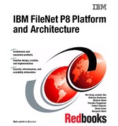
Bowtie design
The bowtie design improves upon the reliability of the stovepipe design but is more complicated to set up and maintain because it adds distribution steps between every component. The additional distribution steps allow components in each tier to be used in a utility fashion. Thus as long as sufficient capacity is available, a bowtie design can withstand many more failures than a stovepipe design.
While the reliability is high, a sacrifice simplicity is caused by having to configure multiple distribution technologies and requires an understanding of how each technology functions to properly troubleshoot problems. An additional complication is managing application state. If a component fails, the component taking over needs to know where the last component left off. Content Engine and Workplace/Workplace XT are typically scaled using the bowtie method and use persistence and transactions to avoid the component state problem. Figure 9-2 on page 283 shows horizontal bowtie scaling.

Figure 9-2 Horizontal bowtie scaling
Transactions and persistence
The bowtie scaling methodology requires the solution to maintain state between unlike components and prevent partially completed tasks from harming the integrity of the information. IBM FIleNet P8 uses transactions to prevent cases where a task is only partially completed due to a failure. In some cases P8 implements persistence internally, but because some components are designed to work in conjunction with third party software, such as the application server, persistence is sometimes managed by external mechanisms.
Connection persistence
Connection persistence ensures an established communication path is maintained between the client and the server for the duration of the TCP connection between the client and the load balancer.
Connection persistence maintains the progression of a multi stage communication by knowing the server behind the distribution layer will always be the same until a new connection is established. The connection is defined by the TCP connection from the client to the load balancer. The load balancer impersonates the server by rewriting the network addresses of the packets between the source and destination.
Connection persistence however depends on the communication occurring over a single connection, that the state does not depend on subsequent connections, and that the communication is not arrive over multiple connection streams. Session persistence is more sophisticated method which addresses these limitations. Though it is unnecessary, Process Engine Internet Inter-ORB Protocol (IIOP) traffic will work with connection persistence.
Session persistence
In the context of P8, session persistence is used to ensure a web session started on one client (web browser) maintains state with the server which started the session. Modern web browsers use multiple streams, multiple connection sequences and protocol specific behaviors which make session persistence necessary for P8 user interfaces and web services to function optimally.
Session persistence in an a J2EE application is managed using a JSESSIONID cookie which is created when a browser first connects to a Java servlet or JSP. This key can be used to identify a users session and allows the load balancer to send traffic with the same JSESSIONID to the same server.
9.3.2 Vertical scaling: Scale up
Vertical scaling, or scaling up, is achieved by moving an application to a more powerful server. Vertical solutions require fewer machines than horizontal solutions because each server manages more traffic, making the day to day maintenance easier. The drawback to this approach is the server upgrade process when application binaries and data are moved to the larger server. Moreover, if demand outpaces the planned capacity an early upgrade will be required. The risk can be minimized if processor cores and memory can be added to an existing server, as this does not require a re-installation of the application.
An application might or might not take full advantage of the server it runs on and can require tuning the application or the operating system. Most commercial software is designed to require administrative intervention to scale vertically. The application servers supported by P8 require changes to the Java Virtual Machine configuration to scale to the capabilities of the server. Application tuning is explored in greater detail in 9.5, “Tuning the IBM FileNet P8 Platform for performance” on page 313.
9.3.3 Server virtualization
Server virtualization allows multiple instances of an operating system to run concurrently on a single physical server. There are many competing technologies for server virtualization, each with different capabilities and strengths. Virtualization methodologies usually fall into one of two categories, hardware isolation or software abstraction.
Software abstraction
Software abstraction is the most common form of server virtualization and is implemented in one of two ways. Full virtualization where the hardware is emulated using software and paravirtulization where the virtualized operating system has more direct access to hardware.
As with most computer technologies, software virtualization is implemented in layers. In an unvirtualized server, the operating system kernel runs directly on the hardware and programs communicate with the kernel to access memory, cpu, and peripherals. Software abstraction de couples the operating system from the hardware and provides great flexibility and granularity. The abstraction layer however adds overhead and imposes a performance penalty. The implementation of the virtualized infrastructure heavily influences the performance of the virtualized operating system.
In a fully virtualized server, a second operating system kernel runs in a program called a hypervisor, emulating the hardware. The operating system running in the hypervisor interacts with a virtual machine in the same way it does with a physical machine. The hypervisor translates requests from the virtual machine to the hardware. Fully virtualized operating systems run natively and only interact with the virtual machine and not the hypervisor directly.
In a para-virtualized design the operating system still runs in a virtual machine that has direct access to the hypervisor, and sometimes the hardware. By bypassing the emulation layer, a paravirtualized operating system will usually outperform an equally configured fully virtualized operating system. The drawback to a para-virtualized machine is having to run an operating system designed to support the calls to the hypervisor.
Hardware isolation
Hardware virtualization divides the resources of the server at the hardware level, thus eliminating the need for a hypervisor. Without the overhead of hypervisor, each virtual machine can run a native version of the operating system at full speed. Although hardware isolation has performance benefits over software isolation, it does not support the ability to share a resource, such as a processor core, between virtual machines. Hardware isolation is found only on the higher-end server hardware.
Virtualization is used to address the following challenges:
•Allows applications that are not supported to run on one server to be co-located on the same physical machine by separating them on individual virtual servers.
•Improves the flexibility in provisioning hardware resources to applications. Components that run in a virtualized environment can more easily be moved to a new server.
•Provides a shared platform using fewer physical servers. Use virtualization to partition the servers into logical units into which the individual applications are installed, thus providing data segregation comparable to a scenario where dedicated physical servers are used.
•More effectively utilizes processor and memory resources, for example two physical servers which run at 25% capacity collectively leave 150% of the available processing power unused. If the two workloads when virtualized on a single server use 50-60% of the available processing power leaving only 40%.
Although IBM supports running IBM FileNet P8 in a virtualized environment, organizations pursuing a virtualization strategy are strongly urged to load test virtualized infrastructure intended for production. The liabilities of some virtual infrastructure designs impose significant performance penalties.
9.3.4 Load balancing
P8 is designed to take advantage of several different load-balancing technologies. Load-balancing is a term to describe the distribution of traffic to more than one instance of an application. Load-balancing is necessary when throughput requirements exceed the capability of a single server.
|
Note: Most load balancers support connection or session persistence. Vendors however have different terms to describe this feature and might refer to the capability as sticky sessions or session affinity.
|
This section describes various load-balancing methodologies which can be used with IBM FileNet P8.
Hardware load balancer
A hardware load balancer is an appliance specifically designed to distribute network traffic to more than one instance of an application. The term hardware load balancer can also be used to describe load balancers implemented in software but implemented on a closed platform, not intended for general purpose computing.
In a typical configuration, a load balancer will distribute traffic to multiple servers and functions by impersonating a single server. Network traffic directed to a load balancer is inspected and a load-balancing decision is made based upon the content of the traffic in the status of the servers the load balancer is impersonating. A load balancer uses a singular IP address to accept traffic which is sometimes called a virtual server or virtual IP (VIP). The systems the load balancer accepts traffic for are collectively referred to as a resource pool or server pool. Each resource in the resource pool is monitored to ensure the load balancer is not direct traffic to an unavailable service.
All hardware load balancers can inspect traffic at the transport layer or layer 4, also called the transmission control protocol (TCP) layer. The layer 4 rule makes balancing decisions based upon the status of the inbound connection. More sophisticated load balancers support routing decisions based upon application layer code, with the broadest support being available for the HTTP protocol. At this layer, a load balancer can enforce session persistence by inspecting the JSESSIONID cookie in the HTTP header. when the load balancer encounters a JSESSIONID it compares the value against previous routing decisions, and sends the traffic to the resource initially chosen to receive the traffic.
When choosing a hardware load balancer for an IBM FileNet P8 system, it must be guaranteed that it meets at least the following criteria:
•Support for TCP and UDP
•Support multiple virtual IP addresses with different rules
•Support session persistence, (session affinity or sticky sessions)
Load balancers typically sold in pairs and installed in a cluster configuration to ensure the load balancer does not become a single point of failure.
Software load balancer
A software load balancer is an application, with similar capabilities to a hardware load balancer, but installable on a general-purpose server. This must not be confused as a web server plug-in or proxy.
Web server plug-in
An application server is often implemented in conjunction with a web server. A specialized plug-in written to support a specific application server works similar to a load balancer. However, plug-ins are restricted to HTTP. The plug-in is configured to be aware of the applications deployed in the application server environment and can make fine grained balancing decisions.
An additional benefit provided by the web server plug-in is the ability to off load functions which do not perform well in Java. The Java language reclaims memory by identifying objects which are no longer in use. This process is called garbage collection. During garbage collection, Java halts all processing and begins reclaiming memory. Every time a client connects a new object which manages the network traffic is created. A web browser will make several socket connections to the application server, transfer some information, and after a period of time, disconnect. because this process repeats itself often it places the burden on the garbage collector. When a web server plug-in is used the burden of managing the socket connections is off loaded to the web server. By reducing the object turnover, the garbage collector runs less often resulting in fewer application pauses.
Java object load balancing
Routing EJB requests across a load balancer might cause undesired results and will behave differently depending upon the choice of application server. Figure 9-3 on page 289 illustrates an IP packet containing a Java object. The frame at the bottom represents the data payload containing the object.
A load balancer works by making changes to the packet and forwarding it to an available server based on rules defined by an administrator. Rules are defined by layers which correspond to the Open Systems Interconnection model. A layer 4 operates at the network layer by changing the Source IP and Destination IP of packets as they arrive at the load balancer. The change causes the client to believe the load balancer is the server, and the server believes the load balancer is the client. Some load balancers have the ability to inspect deeper into the packet and make more intelligent balancing decisions.
From a network perspective, the data layer, or payload, contains application-specific information, for example, a packet from a web server will contain information about HTTP in the data layer. Load balancer can inspect improperly interpreted HTTP and can make decisions based on the state of the protocol. However, the payload of an EJB packet is a binary representation of a Java Object. Java has the ability to transmit a binary image an object over a network, but it requires the class file used to generate the object to interpret the data. The design and intent of a load balancer prevents it from making routing decisions based upon information in the EJB payload.
While the initial connection request can be load balanced, only the port used to negotiate the initial context (the lookup of the content engine server) must be configured in this way. The advantage of this configuration is allowing the EJB communication to function as designed, and simplify the configuration of naming lookups, process which occurs before an EJB connection is established.

Figure 9-3 Packet structure
9.4 Scaling the IBM FileNet P8 core engines
This section illustrates the options for scaling the core engines of IBM FileNet P8.
9.4.1 Workplace/Workplace XT
Workplace includes the Workplace web interface and the Component Manager. You can optionally install Workplace XT which is the preferred user interface. Note, Component Manager is installed with Workplace or Workplace XT.
Workplace/Workplace XT includes:
•Workplace/Workplace XT web application interface
•WebDav servlet
•Process Orchestration Web Service servlet (P8BPMWSBroker)
•Process Engine REST Web Service servlet
The scaling of Workplace XT is described in the following section. The scaling of Workplace is not discussed because it is similar to that of Workplace XT.
|
Application Engine and Workplace naming convention: Application Engine is the official name for Workplace. Application Engine does not equate to Workplace XT. Both Workplace and Workplace XT support a common set of functions but differ in other areas. For consistency of the terminology used in the book, we use Workplace instead of Application Engine throughout the book.
|
Workplace XT web application
Workplace XT and the WebDav, Process Orchestration Web Service, and Process Engine REST Web Service servlets are deployed as a WAR file to an application server and accessed over HTTP. These service can scale vertically, provided the application server is tuned to do so. These components are most commonly scaled horizontally between two or more servers.
|
Note: For availability reasons, avoid the stovepipe approach. A stovepipe configuration will cause a single failure to cut the throughput to the entire application and not just the failed component. Additionally the number of servers required must assume one or more of them will offline. In a two server configuration for example, a single system must be sized to provide acceptable throughput when only one server is active.
|
Workplace XT requires the use of session persistence, also known as sticky sessions. This term refers to a load balancer behavior which causes traffic having a JSESSIONID to always be routed to the same application server. the application server uses the JSESSIONID to match the inbound request to an active HTTP session object. The HTTP session object contains information pertinent to the user which must survive between page loads. This must not be confused connection persistence which will only route based upon the originating IP and the destination port.
Most application servers offer a feature which replicates the HTTP session object to a predefined set of application servers. When a failure occurs, the session object replicated from the failed node is used to maintain state as the user navigates the web application. WorkplaceXT and its associated servlets contain logic which maintains session information without needing to rely on session object replication. As such, this feature does not benefit Workplace XT or the system servlets deployed with it.
Hardware load balancer
Figure 9-4 on page 291 illustrates using a hardware load balancer to distribute the load across a farm of Workplace XT instances.
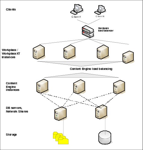
Figure 9-4 Hardware load balancing for Workplace/Workplace XT web application farm
A file system accessible to each instance of Workplace XT is needed for storing configuration data. This is most typically implemented as an NFS or CIFS share. This share must not be provided by any of the Workplace XT servers as this represents a single point of failure. It is advisable to use a highly available NAS device for the purpose. This device need not be a stand-alone device, and the same NAS used to the content provided by the Content Engine can also provide the share.
Web server plug-in
A web server plug-in can also be used to load balance Workplace/Workplace XT. This configuration is useful for incorporating static content, server side includes, or languages other than Java such as Perl, PHP, or Python. Production installations of Workplace/Workplace XT rarely implement load-balancing using a web server plug-in alone, and instead commonly take advantage of both the web server plug-in and a hardware load balancer to simplify the load balancer rules, and shield the application server frequent socket turnover.
Component Manager
The Component Manager runs on the same server as Workplace or Workplace XT, but in a stand-alone Java Virtual Machine. The Component Manager provides the following functionality:
•Dispatches work requests in Component Manager queues to the configured Java classes.
•Allows interaction with configured Java Messaging System (JMS) queues to write JMS messages from within a workflow.
•Performs outgoing web services calls, which are requested by processes that are executed on the Process Engine using system steps with Invoke and Reply instructions.
A single instance of the Component Manager is always bound to one Process Engine-isolated region; therefore, a separate Component Manager instance must be started for each isolated region that the Process Engine uses, in case component integration or process orchestration is used in the processes for that region. Multiple Component Manager instances can be configured using the Process Engine Task Manager.
By default, the Component Manager uses the Content Engine Java API and the WSI transport to connect to the Content Engine and the Process Engine Java API to communicate with the Process Engine. It is supported to configure the Component Manager to use the EJB transport for the Content Engine communication. This is the preferred setup when JMS message queues or if components are used that use client transactions based on the Java Transaction API (JTA) or must get passed the JAAS security context. In this case, we recommend using a separate instance of the Component Manager for each queue using the EJB transport to allow for fine-grained security control.
Using multi threading for components
In the Process Task Manager, you can define how many simultaneous execution threads are used for the component. A thread-safe implementation of the component is required if more than one thread is configured. If thread safety cannot be ensured, it is possible to execute another instance of this component in a separate Component Manager entity.
It is also possible to define multiple Component Manager queues for the same Java Component. However, if these queues are configured to be processed by a single instance of the Component Manager, they are all executed as separate threads in the same Java process by the Component Manager. Thus, defining multiple queues for the same component and executing them in a single instance of the Component Manager does not avoid problems regarding thread safety.
Running multiple instances of Component Manager
Each Java component configured in the Component Manager is executed in a separate Java process spawned by the Component Manager. The Process Task Manager allows the configuration of multiple Component Manager instances on the same server. For each instance, it can be configured which component queues that processes, which is the preferred approach if components are not thread safe and must be executed in separate Java processes.
Scaling web service call requests by processes
If process orchestration is used heavily, running multiple instances of the Component Manager allows you to scale the throughput for outgoing web service calls that active process instances initiate. Each Component Manager instance can be configured to process the outgoing web services queue (WSRequest). If required, different filter patterns can be defined, for example to ensure that high-priority web service requests are exclusively processed by certain Component Manager instances.
Because incoming web service requests for processes are managed by the P8BPMWSBroker, which is part of the web application (Workplace XT), the throughput for processing incoming web service requests can be increased by farming the web application.
In both cases, verify the Process Engine can handle the additional load caused by the increased web service requests using the Scout sizing tool
Workload distribution
In general, the Component Manager instances poll their work from the configured component queues rather than pushing out requests. An exception to this rule applies when Process Engine notifies a Component Manager instance that new work arrived over the Component Manager event port. This feature can be used to configure a large polling interval for the Component Manager and ensures that new work items are nevertheless processed quickly by the Process Engine notifying the Component Manager. In terms of scaling, it is not required to implement a load management for this notification. It is more efficient to use a smaller polling interval if a large amount of work for the Component Manager is expected, which must be the reason why this component is supposed to be scaled; otherwise, Component Manger instances can run in parallel to increase the number of requests that are processed.
The Component Manager configuration includes the link to the Workplace/Workplace XT web application, which communicates with the Process Orchestration web services servlet. Therefore, in a farmed environment, the virtual address of the load balancer or the http proxy must be configured for the Component Manager instances.
9.4.2 Content Engine
The Content Engine is deployed in a J2EE application server as an EAR file. The EAR file contains the Content Engine EJB, the IBM Axis2 Web Service stack for for the Content Engine (CEWS) and for the Process Engine (PEWS). Content Engine supports the same approach for scaling J2EE applications.
Like the Workplace/Workplace XT, horizontal scaling is the preferred option for applications that run in the context of a J2EE application server because it also provides high availability.
Content Engine, being an EAR, has several components, each with a different load balancing methodology. Figure 9-5 on page 295 shows how hardware and EJB load balancing are used to scale the Content Engine.

Figure 9-5 Recommended load balancing configuration
Content Engine EJB
The Content Engine EJB is implemented as a set of stateless session beans. A stateless session bean performs work on behalf of a client and relies upon services provided by the application server. A client application using the Content Engine API specifies a URI which indicates to the API how to connect to the Content Engine server. Within the API the client creates an instance of a Content Engine Java object and transmits it to the Content Engine server to be processed. This process requires a TCP connection from the client and server for the duration of the time needed for the object be created, sent to Content Engine, the work performed, and the results returned. Session beans are stateless but only on a per connection basis. This requires that after an object is sent to the server the methods of that object must run, must run on the same server.
The load distribution for EJB traffic is a function of the application server. Thus the use a hardware load balancer is not necessary. Content Engine servers are deployed in groups called clusters. The cluster is responsible for workload distribution. The EJB communication process differs between application server vendors, but they all follow the same basic procedure. A specialized URI is used by the EJB client containing the host names and addresses of the EJB servers. Upon reply, a member of the EJB cluster is elected to handle communication until the network connection from a client terminates.
In the case of IBM WebSphere Application Server, EJB communication occurs over IIOP which is an implementation of General Inter-ORB Protocol (GIOP) over TCP. In cases where Content Engine is scaled horizontally using a cluster, the communication begins when the client causes the Content Engine API to create the initial context (the initial context provides a Context object which is used to perform a JNDI lookup for the Content Engine EJB using the “/FileNet/Engine” context name). The corbaloc URI, runs on a dedicated port and is used to locate a resource which can respond on behalf of the cluster. The sequence completes when the properties needed to locate a Content Engine instance are returned. Several sources can be used for the corbaloc URI, including WebSphere deployment manager, or an available WebSphere node agent. In most cases it is best to use the host and IP addresses of application servers where Content Engine is deployed. After the location of the Content Engine service is established communication occurs over a different port called the ORB_LISTENER_ADDRESS. The ORB_LISTENER_ADDRESS is dynamically assigned by the application server. The client will maintain the TCP connection to this address for as long as the client is alive but there’s no guarantee the address will be the same on subsequent connections.
While a load balancer can be used to simplify the URI and load balance the initial context creation process, ultimately the ORB_LISTENER_ADDRESS will be used from that point forward and bypass the load balancer completely.
|
Note: In cases where a firewall must be installed between the Content Engine and the Workplace/Workplace XT, the ORB_LISTENER_ADDRESS can be fixed to a specific address and port. Additionally the firewall administrator must ensure the firewall is configured to allow connections to be persisted from the Content Engine client to the Content Engine server. Most firewalls are configured to break these connections by default.
|
Web Services Servlet
Web services servlet provides access to web services API for Process Engine and Content Engine. It is important to recognize the distinction between the Process Engine web service and the Process Engine Orchestration web service which is provided by the Workplace/Workplace XT. The Process Engine and Content Engine web services are implemented over HTTP and can be scaled using multiple instances and the load balancer implemented either in hardware, a web server plug-in, or both. It is highly advisable to protect all web services with the web server plug-in. There is no guarantee a client implementing a web services API call avoids performance impacting behavior, such as frequently connecting and disconnecting.
Content storage
Table 9-3 shows the options for storing content elements with the Content Engine. See 2.2.5, “Content storage” on page 31 for more information.
Table 9-3 Storage options for Content Engine
|
Storage area
|
Description
|
|
File storage area
|
Content stored in a folder hierarchy on a shared file system
|
|
Database storage area
|
Content stored as binary object (BLOB) in the object store database
|
|
Fixed storage area
|
Content stored on a supported fixed content device such as FileNet Image Services, IBM N-Series SnapLock, or IBM Information Archive)
|
A storage subsystem can become a throughput bottleneck affecting ingestion or retrieval rates. This is particularly important for functions outside the context of the application and inside.
|
Note: Always assign document classes a storage policy and not a storage area. A storage policy allows an administrator to mark storage areas read only for archival purposes. Storage areas assigned directly to a document class can be marked read-only, but subsequent check in and check out of content of the same class will never be routed to a new storage area.
|
File storage area
A file storage area must be considered as a first choice for storing content if business requirements allow:
•Storage of the content itself represents the largest investment of storage required in a FileNet system. A file storage area offers the broadest choice of storage offerings to keep cost low.
•Storage policies can point to several storage areas and balance the distribution of content to them. Doing so reduces the risk of congesting a storage area’s inbound folder into which each content element is placed prior to being moved into the final location. A file storage area allows an administrator to control directories where content is stored and masks changes made to the underlying storage infrastructure from the FileNet application. For details about this process, refer to IBM FileNet Content Manager Implementation Best Practices and Recommendations, SG24-7547.
•File storage areas can be implemented on NAS storage, such as IBM N-Series to take advantage of advanced features, such as snapshots, replication, and data cloning.
|
Note: Some file systems are designed to perform well for small files where others are designed to perform well for large files. ECM applications store many small files which are accessed randomly. File systems not designed for small file storage will demonstrate performance problems as the number of files increase.
|
Database storage area
Using a database storage area requires that all content is transferred into a single object store database. Whereas it is possible to scale the uploading units by adding Content Engine servers, all content elements must be received and stored by the database engine. This traffic uses the same infrastructure components of the J2EE server, such as the metadata, for example the JDBC connection pool to the database. Compared to the file store example previously discussed, there are fewer options to establish parallel communication channels. Thus scaling relies heavily on the capability of the underlying database system.
A database storage area delivers the benefit that content and metadata is stored in a single database, which makes backup and restore scenarios easier because there is no need to ensure synchronization between a file system or fixed content device and the metadata database. Organizations that choose to use the database as the storage area must configure the database so that the content is stored separately from the metadata.
Fixed storage area
Fixed storage areas are often used if the system must meet data retention requirements. In many cases, it is easier to ensure, on the level of the storage device, that content that is written one time cannot be changed later on for a defined period of time (referred to as the retention period). Based on the concept of the content life cycle (refer to 7.2.2, “Document life cycle” on page 173), the Content Engine allows the content to be moved to such a device, for example when a status is reached where content is archived for a certain retention period.
Fixed storage areas, require a staging area accessible to every instance of Content Engine. New content elements are placed into this staging area before they are moved to their final destination on the fixed content device. For high ingestion rates, multiple staging areas can be load balanced using a storage policy, although this does not change the fact that a single fixed-content device finally stores all of the content elements.
Benchmark
In various benchmarks, the Content Engine delivers excellent performance and scales extraordinarily well. Content Engine demonstrates near-linear growth in throughput when additional instances were added to the Content Engine farm. Refer to the white paper IBM FileNet P8 4.0: Content Engine Performance and Scalability1 for details.
A cluster of 16 Content Engine servers was benchmarked using a single object store. Results indicate that the performance of the database becomes a bottleneck before Content Engine demonstrates nonlinear scalability. Database technologies such as IBM DB2 pureScale, and using multiple object stores on different databases, can be used to scale Content Engine even further.
9.4.3 Full-text indexing
The P8 Platform provides the ability for full-text indexing on documents and their metadata through Content Search Services and the Legacy Content Search Engine.
Two major functions of the Content Search Engine are:
•Create full-text index information
•Execute content based retrieval (CBR) queries utilizing the fulltext index
Content Search Services
This section discusses Content Search Services (CSS)
Indexing scalability
The Content Engine allows for multiple CSS servers to be configured for a P8 site. A CSS server might be configured in index, search, or index and search mode. Only CSS servers configured in index or index and search mode can perform full text indexing. CSS natively supports farming of index servers to allow for greater throughput of indexing requests. To enable farming, all index servers in the site must have access to the index areas. An index area consists of index files that contain index information for the objects that belong to the same indexable base class or subclass of the base class. An index area begins life with one index file and create indexes until the index file’s capacity is reached and will consequently create another index file for additional indexes. An index file can only be accessed by only one index server at a time. The performance benefit of multiple index servers will be seen when there are multiple index files. The way to ensure multiples index files is to either use multiple index areas or to implement index partitioning.
Index partitioning is the grouping of index information into separate indexes based on object property values. CSS allows for index partitioning using a maximum of two properties, one string property and one date property. If an object contains is partitioned using a string property, all objects that have the same value for the property will be stored in the same index. For example, objects containing the string property Department with the value Legal will be grouped together in as separate index. This will result in multiple index files for a given index area based on the different values of the Department property. On creation of the index, an index server is assigned to the index given a lease time for exclusive write access to the index. The index server will relinquish those rights only if the following conditions occur:
1. The index server becomes unavailable and remains unavailable past the expiration of the lease time.
2. The index server’s lease time has expired and the index server has been deemed unfit to maintain ownership based on the total number of indexes owned compared to other index servers in the farm.
The second condition helps with balancing the load across all the registered index servers in the farm. In either instance, a new index server is assigned and given a new lease time and exclusive write access to the index. Potentially, every index file in the index area can be maintained by a separate index server.
Search scalability
Only Content Search Services (CSS) servers configured in search or index and search mode can be used to search indexes. Multiple CSS servers can be registered with a P8 domain to form a farm of search servers. When a Content Based Retrieval (CBR) query is submitted, the Content Engine selects the dual-mode (index and search) server that most recently updated the index as the default search server. If the server is unavailable or is not configured in dual- mode, a random search server is selected and the query is executed with the selected server. As with indexing, all search servers need to have access to the index areas in their P8 site to perform searches.
Legacy Content Search Engine
This section discusses the Legacy Content Search Engine.
Indexing scalability
Autonomy K2 allows you to configure multiple K2 servers to work as a cluster to provide high availability and scaling. This configuration improves the throughput for indexing requests at the level of Autonomy K2 because multiple indexer processes can work in parallel on the different nodes of the Autonomy K2 cluster. Figure 9-6 illustrates the Scaling out Content Search Engine indexing.
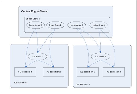
Figure 9-6 Scaling out Content Search Engine indexing
Each server in the Autonomy K2 cluster is configured to handle one or more Index Areas. Using at least two Index Areas on each Autonomy K2 server improves the throughput due to an increase in concurrent writes. Figure 9-6 illustrates a configuration with multiple Autonomy K2 servers and index areas. Each search server handles two search areas in this example.
The Content Engine CBR Executor hands over an indexing request to any of the servers that are configured for the appropriate Index Area in a random fashion, thus distributing the load.
|
Note: Currently, only one CBR dispatcher process can be active for an IBM FileNet Content Manager site. Content Manager provides a feature such that for each site, only one Content Engine server runs the CBR dispatcher process. If one is down, it automatically launches a dispatcher from another server to perform the task.
|
Search scalability
To raise the number of search requests that can be handled simultaneously, the number of Autonomy K2 search servers must be increased. If multiple Autonomy K2 search servers are available, the Autonomy K2 broker process issues the incoming requests to all search servers simultaneously where they get processed concurrently. The Autonomy K2 broker gathers the results that the search servers deliver and returns them to the Content Engine.
Figure 9-7 illustrates the use of multiple Autonomy K2 search servers to scale out content-based retrievals. There is only one Autonomy K2 broker process required (on Autonomy server 1) that accepts the search requests that the Content Engine executes and dispatches them to the search servers.

Figure 9-7 Scaling out Content Search Engine retrievals
We recommend using advanced technologies, such as the classification module, to extract useful metadata from document fulltext instead of purely relying on a fulltext search engine. The availability of such metadata is key in an Enterprise Content Management strategy because it is the fastest way to make content accessible for a wider audience of users. Being able to use metadata, sometimes in conjunction with fulltext information, is the superior concept of relying on the fulltext information as the primary source for finding content.
9.4.4 Process Engine
The Process Engine is a Java application, but it does not run in the context of a J2EE application server. Nevertheless it supports both horizontal and vertical scaling to respond to increasing system demands. The recommended configuration for Process Engine is horizontal scaling. This section highlights the options available for scaling Process Engine:
Single Process Engine server
If the Process Engine system consists only of a single server, scaling vertically is the only available option. The Process Engine functions are executed by worker threads that are controlled by a central broker. This broker manages worker threads that dispatch the process instances (work objects) and the background threads, which manage the email notification and similar tasks.
If additional CPU cores and memory are available, it is possible to increase the number of parallel threads, which enables the Process Engine server to handle an increasing number of work objects.
Farming Process Engine servers
The Process Engine supports farming of Process Engine servers. In such a configuration, multiple Process Engine servers access a shared database that stores the information, such as work objects and queues.
Figure 9-8 on page 304 shows a configuration where two separate applications access a shared Process Engine farm, which is a common configuration because both applications can use different isolated regions, which ensures that work objects do not interfere.
The farming capability introduced IBM FileNet P8 4.0 allows organizations to implement the same concept of scaling horizontally across all core engines of the Platform. In addition, it provides high availability without the need for spare servers running idle.
Figure 9-8 Two node Process Engine server farm with multi-tenancy
Farming the Process Engine servers requires a load balancer to distribute the incoming requests. Because the connections are stateless, connection affinity is not required. Details about the installation and configuration are in the IBM FileNet P8 High Availability Technical Notice.
Using the Process Engine Task Manager, all servers in the Process Engine system can be managed from a central location. This central management includes starting and stopping the Process Engine software on single nodes and removing nodes from or adding nodes to a farm.
Farming is also the preferred way to scale the Process Engine. This concept delivers high availability because the remaining servers continue to deliver the Process Engine functionality if a single node in the farm fails.
IBM conducted benchmark tests that proved a near-linear growth on transactions handled by a Process Engine Farm when additional servers were added to the farm. Because the Process Engine scales extremely well, the database that is the Process Engine farm uses might become the bottleneck when scaling horizontally.
Independent Process Engine servers
The Process Engine system can also be scaled by using independent servers or independent instances. As Figure 9-8 on page 304 illustrates, each Process Engine server uses its own database, which can be hosted on an individual database server. The same configuration is possible for Process Engine instances using independent Process Stores (databases).
Scaling with independent servers is an option to scale when the overall architecture is geographically distributed and work is mainly done locally, for example, the server for application 1, the left Process Engine server, and the left database server can be in Los Angeles; whereas, the servers on the right are located in New York to support another application that is used there. The fact that users in each location always work with local servers and a local database delivers optimal performance.
|
Note: It is recommended that this methodology is used in conjunction with load-balancing. Having singular independent instances or servers without redundancy will mean having to maintain a system with multiple single points of failure.
|
Two alternatives exist regarding the Content Engine for storing the process-related content objects. Both applications can use a shared Content Engine server farm, or both applications can use separate Content Engine servers. In the example of the distributed environment, separate Content Engine servers are configured, one for each location to ensure that the application can locally retrieve the content.
9.4.5 Summary
The IBM FileNet P8 architecture supports horizontal and vertical scaling for all core platform components to respond to increasing system demand. Benchmarks show that IBM FileNet P8 shows nearly-linear scaling over a wide range for both the Content and Process Engine.
Using the approach of farming, the layers for the Workplace/Workplace XT, Content Engine, and Process Engine, IBM FileNet P8 provides a solution that makes it easy to add resources to a given system. The only thing that you must do is provision additional servers (or additional instances on existing servers, where applicable) with the corresponding platform server component, and reconfigure the workload management component to actively use this component.
9.4.6 Scaling add-on products
There are many products that are IBM FileNet P8 based. In this section, we discuss scaling of some of these add-on (expansion) products and modules:
For an introduction to these add-on products, refer to Chapter 2, “Core component architecture” on page 19.
Business Process Framework
The Business Process Framework (BPF) can scale in the same way that the Workplace scales because it has a similar structure. The core components of BPF are:
•The web application that is deployed on a J2EE server
•A Component Manager queue for BPF-related operations that can be triggered by a process executing on the Process Engine
The scaling options for the Workplace found in section in 9.4.1, “Workplace/Workplace XT” on page 289 also apply for BPF. Similarly, we recommend farming the web application to gain benefit from the high availability, which is automatically introduced by this architecture. For the Component Manager that hosts the BPF operations, the best practice is to configure additional instances to handle an increasing number of requests. However, because the BPF operations components are implemented thread safe, it is also possible to configure multiple threads for a single BPF operations queue.
It is important to remember that one BPF application, just like Workplace, can only be configured to use one isolated region. This is no restriction in flexibility, and for the sake of data segregation work objects cannot cross the border between isolated regions. Therefore, it makes sense to implement individual BPF applications for each isolated region.
FileNet eForms
Electronic Forms (eForms) for IBM FileNet P8 is an extension to an Workplace/Workplace XT installation. As such, eForms can be scaled in the same way as a client web application is scaled. Scaling the Workplace/Workplace XT automatically takes care of eForms.
eForms provide several options to integrate with external systems, for example: databases by taking advantage of JDBC lookups or arbitrary systems by using HTTP calls to lookup data. You must ensure that the system that eForms integrates with and the intermediate piece that facilitates this communication (for example, a servlet performing a lookup against a host system) are designed accordingly so that they can handle the increased load that originates from scaling the eForms and the Workplace/Workplace XT.
IBM FileNet Capture
IBM FileNet Capture enables capturing of paper-based documents and faxes and storing them as electronic images in the IBM FileNet Content Manager repository. Capture offers various options to provide metadata for the content, such as automatic extraction, using the ADR module or by manual keying using the indexing application.
Capture was designed to run as a distributed application and supports horizontal and vertical scaling for the different building blocks. Capturing images, performing quality checks, combining images into documents, and adding metadata to the documents before committing them to the repositories can include various steps. The sequence of this capturing process can be expressed as a Capture Path, which describes how the images flow through the different processing steps until they are committed as a part of the document. Capture does not require that a Capture Path is set up, but you can work with the different modules in an ad-hoc mode. To ensure that all steps are executed in the desired sequence, we recommend that you define a Capture Path for this purpose.
The approach to scaling Capture to process a larger amount of documents differs for the components that are used. Modules that require manual interaction by a person, such as the scan operation itself, the quality review, indexing, or indexing review steps, can be scaled horizontally by adding additional PC workstations to the installation. Images are scanned in parallel by the scan stations into separate batches that are managed in a database, and the Capture Path ensures that indexing and review stations pull images from these batches for further processing. By adding PC workstations, more people can work in parallel on the different batches.
Modules that perform automated tasks, especially ADR recognition components that extract data from the images using statistical methods can be scaled vertically, and adding processing power to an ADR server improves its performance and increases the throughput. Scaling horizontally by increasing the number of ADR servers is the other option that is available for these parts of the ADR installation.
IBM Content Collector
IBM Content Collector consists of three major building blocks:
•An archiving engine
•Web applications and configuration service running on an embedded IBM WebSphere Application Server
•Legacy access components
Content Collector supports horizontal scaling for all components to increase the throughput for archiving new content and for serving a larger amount of users.
A horizontal form of Content Collector servers is called a Content Collector cluster. Because Content Collector runs on Windows operating systems only, there is no option to scale Content Collector vertically, except for using virtualization. Content Collector is a component that heavily uses the network to connect to the Content Engine for storing content. Therefore, we do not recommend using virtualization to run multiple instances of Content Collector on a single physical server.
Figure 9-9 on page 309 illustrates the setup of an Content Collector cluster. The (primary) Content Collector server runs the core components. In addition, the configuration manager and the initial configuration template are hosted on this system. When additional servers are installed to form the cluster, they use the installation procedure for the expansion server, which only runs the core components.
All configuration for the Content Collector system is stored in a central configuration database that all servers in the Content Collector cluster access.
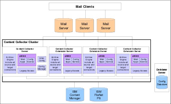
Figure 9-9 Horizontal scaling for Content Collector
|
Scaling Content Collector: Content Collector performs retrieval by communicating directly with Content Engine; therefore, Content Collector must be scaled as utilization grows. This approach is different from its predecessor IBM FileNet E-mail Manager, which uses the Workplace/Workplace XT to retrieve and display content and thus relies on scaling the Workplace/Workplace XT to ensure speedy retrieval.
|
Connectors for Quickr, SharePoint, and SAP
The connectors for Quickr, SharePoint, and SAP consist of a repository connector component (the connector for SharePoint document libraries) that transfers content from the collaboration environment into the ECM system and extensions for the collaboration web portal application, which allow direct access objects in the Content and Process Engine from the collaboration environment. These extensions are only used for retrieval purposes from the collaborative web portal.
Collecting and transferring content
The connector for document libraries collects the content from the document libraries in the collaboration environment, transfers it into the Content Engine, and (depending on the configuration) performs other tasks, such as creating a stub. The connector for Quickr document libraries currently allows you to collect content manually, not based on business rules, such as the SharePoint connector. For that reason, scaling mainly refers to the SharePoint connector. This component can be scaled vertically on a single server because the number of threads can be adjusted to the processing power of the underlying server hardware.
Additionally, if multiple Quickr or SharePoint instances are connected to the ECM repository, it is possible to distribute the overall load by installing and configuring individual instances of the connectors for a dedicated set of Quickr or SharePoint instances.
Retrieving content
The connector for SharePoint Web parts or Quickr Web portal forms the component that is used for retrieval purposes. From a technical point-of-view, it uses the Content Engine and Process Engine APIs to connect to the back end. Content retrievals are executed by calling the appropriate functions of the Workplace UI Service.
The retrieval part can be scaled horizontally using a farm of SharePoint servers, for example. The web parts are then installed on each server of the SharePoint farm, and therefore an increasing number of users and requests can be handled. Because the retrievals are triggered by persons working with the collaborative environment, increasing retrievals from the ECM system is typically seen if more users are working with the collaborative environment, so that a farmed environment might already be in place.
Because the content retrieval uses the Workplace/Workplace XT functionality, you must consider the impact of increasing retrievals on the Workplace/Workplace XT load. As illustrated earlier, the Workplace/Workplace XT can easily be scaled horizontally.
Case Analyzer
The Case Analyzer extracts data from the Process Engine event log tables and feeds them into its internal data warehouse. On a scheduled time interval, the data is aggregated into an internal data mart and from this representation OLAP cubes are derived, which can then be analyzed further by OLAP-aware tools, such as Cognos or Microsoft Excel. Converting data from the warehouse into the data mart and calculating the OLAP cubes is a labor-intensive job.
With IBM FileNet P8 release 5.0, the Case Analyzer can be scaled horizontally to deliver higher throughput and faster calculation times. Case Analyzer is a J2EE application which uses IBM Mashup Center and is deployable to a supported application server. Case Analyzer is scaled using the same methodology as IBM Mashup Center.
Process Simulator
The Process Simulator uses a process definition, arrival and work shift patterns, and probabilities for conditional routes to predict the flow of process instances, thus enabling it to perform what-if assessments to eliminate bottlenecks in existing processes or avoid them for planned processes.
The Process Simulator can be scaled vertically by adding additional CPU and RAM to the server on which this component is installed. Because the process simulator does not have to process items on the magnitude level of a production system, it is most likely that this component will not become a bottleneck.
9.4.7 IBM FileNet Image Services
IBM FileNet Image Services is an image management repository that was designed to efficiently handle large amounts of electronic images. The Image Services architecture is optimized to deliver world-class storage and retrieval performance while managing billions of image documents. Content Engine uses Content Federation Services (CFS) to utilize Image Services as a repository for IBM FileNet P8. Figure 9-10 illustrates the basic layers of the Image Services architecture.

Figure 9-10 Image Services architecture
In Figure 9-10 on page 311, the lower layer is the data tier that Image Services use to store the images that are managed and the data that is related to them. Some important building blocks are:
•The relational database that holds the metadata for the images.
•The multi key file (MKF) database that stores the location for each image on the storage media.
•The magnetic cache regions that provide efficient batch document ingestion and speed up retrieval times, especially for documents that are stored on optical media.
•The optical and magnetic storage and retrieval systems.
Image Services supports a large variety of storage subsystem that can be used to store the images, such as Jukeboxes (optical storage), and several magnetic storage systems, such as disk, IBM DR-550 compliance storage, IBM N-Series with SnapLock, and EMC Centera. For a complete list of supported systems, refer to the Image Services Hardware and Software Guide:
In Figure 9-10 on page 311, the services layer provides the services that are required to manage the stored documents. It consists of:
•Document storage and retrieval services that write and retrieve the objects to the storage system
•Indexing services that manage the associated metadata
•Cache services that manage the cache regions that are used
•Security services that provide access control to documents
•Search services that allow you to quickly locate documents based on their metadata
Image Services are designed to work as a distributed application and are implemented as a set of logical services, which means that many of the components that are listed in Figure 9-10 on page 311 can be spread over different servers. In earlier times, when only optical media was used as long term storage, multiple OSAR servers where frequently used because they provided the required number of SCSI ports to connect a larger number of optical jukebox libraries. It is also possible to off load components, such as the indexing services or cache services, to one or more dedicated servers. Therefore, Image Services supports horizontal scaling.
Image Services is also optimized to effectively use the resources that the host server provides. As such, all Image Services component can be executed on a single system that provides vertical scaling. However, for systems that must connect to a large number of optical jukeboxes, the required number of SCSI controllers can be a limiting factor for pure vertical scaling.
9.5 Tuning the IBM FileNet P8 Platform for performance
For the IBM FileNet P8 infrastructure components that run in the context of a J2EE application server, at first glance, there is only a limited difference between the approach of scaling vertically versus horizontally because in both cases a farm of application server nodes is created. However, both alternatives show significant differences in that a hardware resource, such as memory or an I/O subsystem, must be shared between the different entities in the case of vertical scaling (comparable to virtualization).
There can be a benefit for vertical scaling because any communication between the components that run on the same physical machine do not have to travel over the wire. However, this does not apply if all Content Engine instances run on server1 and all Workplace/Workplace XT instances run on a different server2 because there will be no direct communication between the Content Engine nodes but instead the majority of the traffic is seen either between Content Engine and the database and the storage subsystem and between the Content Engine and the Workplace/Workplace XT. Therefore, vertical scaling can show performance benefits if the IBM FileNet P8 core server components Workplace/Workplace XT, Content Engine, and Process Engine are running on the same physical machine, thus providing minimum latency and maximum bandwidth for the communication path. For installations that make no or only limited use of the Process Engine, this concept might be applied to the Application and Content Engine only.
Refer to the IBM FileNet P8 4.0 Performance Tuning Guide for additional information and recommendations:
9.5.1 J2EE Application Server
J2EE Application Server performance can be optimized in Java Virtual Machine and through connection pooling.
Java Virtual Machine
The Content Engine and the web application of the Workplace/Workplace XT are deployed into separate instances of a J2EE application server.
One critical aspect regarding performance is the garbage collection (GC). Garbage collection refers to an activity where the Java Virtual Machine (JVM) re-organizes its memory heap, deletes all references to objects that are no longer used, and frees this memory for new objects. The larger the amount of memory that was configured for the JVM, the longer this garbage collection cycle takes and the more server resources are used for the garbage collection. The important point is that during the full garbage collection cycle of the JVM, all applications that run in the JVM do not respond. With 2 GB of memory, the garbage collection cycle can take 30 seconds or longer, depending on the resources that are available for the JVM.
On the other hand, the JVM needs a certain amount of memory to run the application. If there is a small amount of memory available, the JVM either often undergoes garbage collection cycles or throws an out of memory exception and eventually crash the application.
In general, the memory requirements of the Content Engine, and especially the Workplace/Workplace XT, strongly depend on the usage pattern. We recommend starting with a configuration of 1 GB of memory for the JVM of each Workplace/Workplace XT and web application and 2 GB of memory for the JVM of each Content Engine.
To speed up the GC process, we recommend that you configure the generational concurrent GC strategy to reduce to the minimum the pauses that the GC cycles cause. On the downside, this strategy reduces the memory throughput to accomplish the improved GC cycles.
|
Note: For high-ingestion scenarios, which create a large amount of
short-living objects in the Content Engine, it can be beneficial to provide additional space in the tenured generations of the JVM heap by adjusting the ratios accordingly. |
It is important to understand that different load patterns might require different JVM tuning to achieve optimal performance, for instance, it can be helpful to configure dedicated Content Engine instances for import purposes that run on J2EE application server instances that are optimized for high-ingestion performance; whereas, other Content Engine instances that are primarily used for retrieval use a different JVM configuration. If high volume ingestion is primarily performed over night, it can be beneficial to use scripts to shutdown the J2EE application server, change the JVM configuration accordingly, and then start the import jobs and switch back to an alternative JVM configuration for the daytime operations.
We highly recommend that you validate and monitor the effectiveness of the JVM performance tuning by using the appropriate tools, such as Tivoli Performance Monitoring (TPM) or similar.
Connection pools
The Content Engine uses the configured connection pools to communicate with the GCD and the object store databases. It is mandatory to adjust the maximum connections parameter for the data sources to the expected number of client connections. Refer to the IBM FileNet P8 Performance Tuning guide for detailed formulas to calculate the connection pool size dependant of the client connections expected.
9.5.2 Database
Content Engine and Process Engine use databases to store and retrieve information about content and process objects. It is important to configure the database accordingly to achieve optimum performance.
Database indexes
As a general guideline, it is important to know which queries are performed against the databases to create the required database indexes for preventing full table scans. Both Content Engine and Process Engine support the creation of database indexes through the administrative tools Enterprise Manager and the Process Configuration Console. In many situations, simple database indexes are not sufficient because the queries that the API creates only benefits from complex indexes, such as a combined index. IBM FileNet P8 supports the creation of combined indexes for the Content Engine using the tools provided by the database vendor and for the Process Engine by using the Process Configuration Console.
Index skew
The distribution of values in an index might become uneven, for instance if half of the objects have the same value for an indexed metadata property. This situation is described as index skew and results in the database not using the index anymore and performing a full table scan instead, even for searches that actually benefit from the index. By changing the query optimizer statistics strategy, as described in detail in the Performance Tuning Guide, the database can be instructed to use the index for those queries that refer to values in the index that are used only for a few objects.
Statistics collection
It is important to ensure that the statistics collection for the database query optimizer is run periodically and that the tools supplied by the database vendor are utilized, which helps to identify long running queries and suggest additional indexes to remedy these situations. In case the query optimizer is tuned manually, it is important to update the job profiles for the statistics collection on the database accordingly so that the changes are reflected and not overwritten with a default statistics job.
In high ingestion scenarios, using multiple object stores is beneficial because it allows you, at least, to address different tablespaces (DB2 or Oracle) or different databases (MSSQL) that can be physically located on different disks on the database server. Object store databases can also reside on different database instances or database servers that offer an additional degree of freedom for distributing the load.
9.5.3 Application design
Any performance optimization at the level of the IBM FileNet P8 Platform servers cannot remedy severe flaws in the application design or the data model of a custom implementation. The Performance Tuning Guide lists important recommendations to remember when designing individual applications. The Content Engine can effectively manage billions of objects. However, to ensure proper response times, the application must avoid critical queries or design patterns.
The Content Engine data model does not restrict the number of objects or subfolders that can be filed into a single folder. Retrieving all content for a given folder is a memory-intensive operation, if many objects are filed into this folder because the Content Engine stores the result set in memory to perform additional operations, such as access control. Therefore we recommend either limiting the number of objects (folders, documents, custom objects) that are filed into a single folder to a number of 200 maximum or ensuring, by application design, that retrievals to the content of folders that have to contain a much larger number of objects are properly filtered so that the retrieval does not return more than 100-200 hits.
|
Index skew: A single folder that contains a large number of objects (subfolders, documents, custom objects) is subject to cause index skew, as described in section 9.5.2, “Database” on page 315, because all objects have the same value for the indexed attribute tail_id in the containment relationship table.
|
The Content Engine API version 4.0 supports a paging parameter (continuable flag), which allows you to subsequently retrieve chunks of result sets. We recommend that you use this option carefully because it might negatively impact the performance. Let us assume a query that returns 10,000 objects. If this query is executed with the continuable flag set to true and a paging size of 50 objects, the database is still treated to retrieval all 10,000 objects and then sort the top 50 results for the first page. In such a situation, it is significantly faster to execute the query to the Content Engine using a select top 50 ... clause and turning the continuable flag off.
For performance reasons, we recommend cleaning up the Content Engine Audit Event table and the Process Engine Event Log tables on a regular basis. A best practice approach is to export all data that is related to work objects that were terminated and for content objects, which are linked to terminated workflows, if this data is needed for audit or compliance purposes and delete them from the corresponding tables afterwards. Again, the event-based architecture of the IBM FileNet P8 Platform helps to identify the correct objects for exporting and deleting.
9.6 Distributing an IBM FileNet P8 system
The modular nature of the IBM FileNet P8 Platform and its scalability are important benefits when designing ECM solutions. Using IBM FileNet P8 Platform you can install components of the complete system at different locations to address given infrastructure restrictions (networks) and to improve the overall performance that the users experience. Throughout this section, we discuss how to approach the design of a distributed IBM FileNet P8 system.
9.6.1 Geographically dispersed users
Large organizations must support content management and content-centric processes over a large variety of geographical locations.
IBM FileNet P8 Platform offers a lot of configuration options that support the design of a distributed ECM system, and we briefly highlight the most important architectural building in this section. Refer to the IBM FileNet P8 Distributed Deployment White Paper2 for a detailed treatment of the best practices for distributing an IBM FileNet P8 system.
Centralized IBM FileNet P8 system
In some cases a central IBM FileNet P8 system that clients access from different locations might be a valid solution. Alternatively, desktop virtualization technologies, such as Citrix or Windows Terminal Services, can also help to make applications available in various branch offices without installing servers locally.
Figure 9-11 on page 319 illustrates the architecture of a central IBM FileNet P8 system. All components are hosted at the central site, and the client at the remote site uses a wide area network (WAN) connection to communicate with the Workplace/Workplace XT.
The benefit of this configuration is the short distance between all of the core components, namely the Workplace/Workplace XT, Content Engine, Process Engine, and the storage layer (file systems for File Stores and databases). Additionally, managing a centralized system is easier compared to dealing with a distributed installation and its added complexity, especially backing up the data in a distributed topology can become a challenge.

Figure 9-11 Central IBM FileNet P8 system
However, use cases remain that cannot be addressed by a centralized approach, for instance, in some countries legal rules exist that require that certain content must only be stored in the boundaries of the country itself. Another example is the work with large content objects, where a distributed storage is desirable to reduce the need to download the content from the central system to the remote location.
In general, we recommend starting with a central system and adding components at larger remote sites, if required.
Distributing Workplace/Workplace XT and Content Engine
The centralized approach can be easily extended by adding Workplace/Workplace XT and Content Engine servers at a remote location, which is illustrated in Figure 9-12.

Figure 9-12 IBM FileNet P8 system with remote Workplace/Workplace XT and Content Engine
In Figure 9-12, the client at the remote site communicates with the Workplace at the same location. The Workplace connects to the local Content Engine and the remote Process Engine. This configuration benefits from the Content Engine cache so that content objects that are created at the remote site automatically remain in the local cache.
Content objects can also be preloaded to the cache at the remote site if they are created at the central site. For this purpose, either the event-based architecture of the Content Engine is used or the prefetch can be initiated from a workflow by using an appropriate Java component. The preferred method depends on the question, when the decision can be made, and if the content object is processed at the remote site and a prefetch is required.
In addition, a feature called request forwarding can be exploited to improve the performance at the remote site. Request forwarding allows the Content Engine that is at the remote location to forward queries to the central Content Engine for processing. The idea is that processing the request might include several round trips between the Content Engine and the object store database. By forwarding this request to the Content Engine that is located closely to the database server and only getting back the result set, there is less communication over the WAN connection.
Remote Workplace only
It is also an option to only deploy the Workplace at the remote site. In this configuration, the remote client benefits from a close proximity to the Workplace, but the downside is the WAN connection between the Workplace and the back end servers Content and Process Engine.
Because the Workplace does not provide content caching, content objects might travel several times to the remote location, for instance, if they are requested more than one time, which can be a problem, especially when working with large content objects.
Deploying only the Workplace at the remote site has advantages, mainly for applications where the client and the Workplace heavily communicate with each other and where latencies between the client and the Workplace are significantly reducing the response times that the users experience.
Process Engine
Distributing the Process Engine is significantly more complex because of the nature of data that this component processes. Process Engine work objects are typically much smaller in size compared to the content objects, so that limited bandwidth between the remote location and the Process Engine Server does not impact the performance too much. However, the effect of latencies on the WAN is still encountered. Furthermore, for content-centric processes, the work objects are not only processed by human participants, but there are also interactions with external systems that, in most cases, also were not distributed.
Also, take into account that the Process Engine’s high transaction nature results in a large number of communications between the Process Engine Server and the Process Engine database because all work objects that are handled are managed in the database. Thus, a distributed Process Engine requires a Process Engine database at that location, too. It is important to understand, that the caching concept for Content Engine also stores the content objects locally only, not the metadata information, which is because the information in a database is subject to change more frequently than the content itself. For the Process Engine, this distinction cannot occur because the process instances that are managed are typically small in size and underlie frequent updates.
We recommend using a central Process Engine and distributed Application and Content Engines for most scenarios, as shown in Figure 9-12 on page 320. This topology benefits from the number of communications between the Workplace and the Content Engine towards the Process Engine. The Process Engine APIs are significantly less than the number of individual transactions that the Process Engine executes on the database.
Alternatively, if the process instances primarily remain in geographical regions, for example, when processing customer requests in North America and Europe, setting up different Process Engine systems for each region improves the performance, as illustrated in Figure 9-13 on page 323.
In Figure 9-13 on page 323, the master system is located in North America and consists of the Workplace (WP NA), Content Engine (CE NA), and Process Engine (PE NA). A database server at this location (DB NA) hosts the Content Engine GCD and object store databases for North America and the Process Engine database for North America. A file server (FS NA) provides the storage areas for content in this location.
The other system is located in Europe and also consists of the Workplace (WP EU), Content Engine (CE EU), and Process Engine (PE EU). Content is stored locally on a file server (FS EU), which either works as a pure content cache or also provides local file storage areas, depending on the detailed requirements. The process instances are managed in a local database (DB EU). European Object Stores are hosted on the database DB EU. However, the GCD information is always stored at one location only, in this case in North America. Access to content metadata for the remote location can benefit from request forwarding between the two Content Engines.
The downside of this approach is that work items cannot be transferred between both systems. Nevertheless, a client at one location can access the applications at both locations and can thus process the work items at the remote location (dotted line). However, when working with the remote Process Engine system, the access is over the WAN.

Figure 9-13 Distributed Process Engines
9.6.2 Disaster recovery
Disaster recovery (DR) addresses the loss of a complete data center or a complete site due to natural or man made disasters, such as fire, floods, or terrorist attacks. The goal of a disaster recovery strategy is to achieve business continuity with minimum interruption and data loss.
We do not want to go into the details of DR options for the IBM FileNet P8 Platform in this book because more details on this topic are discussed in the IBM FileNet P8 Disaster Recovery Technical Note3. We want to point out that disaster recovery and distributing IBM FileNet P8 systems are essentially two separate aspects. However, there are some interesting common aspects.
With the support of horizontal farming for all core components of the IBM FileNet P8 Platform, you might consider stretching the nodes server farms over a wider geographic area, for instance, in a metropolitan area network (MAN) with distances of up to 100 kilometers. Combined with mirroring the data layer (databases and file stores) such a configuration might theoretically address high availability and disaster recovery without the costs that are involved in implementing a dedicated disaster recovery infrastructure.
We do not recommend this simple approach because stretching the nodes of the farm introduces additional latencies for signals that travel over the wire and also introduce a new point-of-failure into the system topology, namely the MAN network. Typically this network is provided by an external service provider and is not as much inter control like the local area network (LAN), for instance, network lines might become interrupted by construction work, thus it will be required to implement redundancy by using multiple MAN connections, in the best case using different physical paths.
In addition, the MAN introduces additional latencies that are experienced in the communication between the different engines. We recommend that the distance between the two locations that are supposed to host the stretched farm be small (for example, 1-5 km) so that the impact of latencies is neglected, when considering the approach of a starched farm. On the other side, such a close proximity might not be able to address full disaster recovery needs.
As described in the Technical Note3, the best practice approach for an IBM FileNet P8 system is to implement high availability using locally redundant components, such as a farm of servers, and to address disaster recovery by setting up a dedicated infrastructure at a secondary data center.
|
Note: By combining the capabilities of modern load balancing devices and a sophisticated configuration, it is possible to reuse the disaster recovery hardware, for example, as a test or QA platform, and reconfigure it in case a disaster occurs.
|
9.7 IBM FileNet P8 in a DMZ environment
There are several use cases where an IBM FileNet P8 system is accessed not only internally by persons that are part of the organization, but also externally, for example by business partners or by customers, especially deployments that use business process management might incorporate access from external participants, for instance, a claim process might be started by a customer using a web based self service portal. The customer is supposed to be able to track the progress of his or her cases based on a portal application. External experts can be part of the process, and they might upload content, such as pictures of the damage or reports into the case management system. Typically, organizations allow access for external participants to their internal systems only through a demilitarized zone (DMZ).
As described in Table 9-1 on page 278, a DMZ is typically an area that is secured and separated from the outside word (the Internet) and from the internal network by two different firewall systems. The aim is to reduce the risk that intruders from the Internet can get unauthorized access to the internal IT systems. To achieve the optimum protection, the protocols and ports that the firewalls route are restricted as much as possible.

Figure 9-14 DMZ with dual firewalls
The internal clients can access the internal servers directly or through a separate firewall.
Web server with http proxy in the DMZ
The best practice approach for a DMZ deployment is to implement a clear separation between the IBM FileNet P8 servers in the internal network and the external clients outside of the DMZ by web servers with http proxy capabilities. This reverse proxy must be transparent for both the external clients and for the IBM FileNet P8 servers.
In a typical scenario, the web servers in the DMZ host some (in most cases) static external web applications and also perform some sort of load balancing in the way that they distribute incoming request to the internal servers. These web servers are typically not only used by the IBM FileNet P8 applications, but also by other applications that need access from external clients. The web servers are configured to forward incoming requests based on the URL to the appropriate internal servers. Figure 9-15 on page 327 illustrates this scenario.
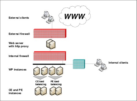
Figure 9-15 IBM FileNet P8 DMZ deployment best practice
For the external clients, the reverse proxy acts as the application server, and for the application server, the reverse proxy acts as the client. Therefore the reverse proxy must rewrite any packets that come from the external client in a way that they seem to originate from the reverse proxy server instead, which ensures that the application server passes the response to the reverse proxy server instead of trying to directly contact the client. Conversely, the reverse proxy must rewrite any response that it receives from the application server in a way that it seems to originate from the reverse proxy. This setup ensures that the client who evaluates the response reconnects to the reverse proxy for subsequent requests instead of directly trying to access the application server, which fail because the application server is behind the internal firewall.
Workplace in the DMZ
Under certain conditions, it is beneficial to put the Workplace for external users into the DMZ. In this scenario, the Workplace, or a farm of Workplace servers, are installed at the level of the DMZ to serve the clients in the external network. Typically, there is another set of Workplace Servers that run in the internal network that serve the internal clients and that also run the Component Manager instances. Figure 9-16 on page 328 illustrates this configuration. The other internal servers, such as Content Engine and Process Engine, are not shown.

Figure 9-16 Workplace (WP) in the DMZ
This architecture, in Figure 9-16, delivers the benefit that clients can directly access the Workplace, which can be mandatory, for example, if HTTPS communication between the client and the Workplace is intended to be used for external clients, and the HTTPS protocol cannot be routed across the DMZ.
9.8 Sample deployment
When designing an IBM FileNet P8 system, architects are not limited to exclusively adhering to only one of the concepts that we mentioned in 9.4.2, “Content Engine” on page 294, for scaling the Content Engine and managing the workload. Instead, in most cases we see a combination of different approaches to cover the full spectrum of applications. Typically, this involves application server work management for applications using the Java API and the EJB transport and hardware load balancing or an http plug-in for web services clients.
In this section, for a sample deployment, we describe how virtualization can be used to effectively take advantage of hardware resources for a shared platform.
We assume that the following requirements are given for the sample deployment:
•Implementation of a shared infrastructure that serves multiple IBM FileNet P8 based projects.
•Template-style approach for using cloning to create the environment for a new application.
•Implementation of high availability for each application.
•Use AIX as the operating system, and limit the number of LPARs.
Based on the requirements, the following system architecture is derived:
•For each application, a separate set of the three IBM FileNet P8 core engines are installed into one separate LPAR.
•Use another LPAR for each application that runs the database and the storage for this application.
•Use farming for the IBM FileNet P8 core engines (Workplace, Content Engine, Process Engine) to ensure high availability.
•Use a traditional active passive HA cluster for the database and the NFS server (refer to the IBM FileNet Content Manager Implementation Best Practices IBM Redbooks publication4 for a detail description of HA clusters).
•Use two separate IBM p570 servers to achieve redundancy at hardware level and distribute the nodes of each farm across both servers.
•Use a set of two redundant hardware load balancers to distribute the load across the Workplace and Process Engine farms and for the Content Engine WSI transport.
•Use application server-based work management for the Content Engine farms for the EJB transport.
Figure 9-17 on page 330 illustrates the basic idea of installing an IBM FileNet P8 domain into two LPARs. The LPAR named “LPAR application” hosts the IBM FileNet P8 core engines and is accompanied by a second LPAR (LPAR storage) on the same physical machine that provides the database and content storage.

Figure 9-17 Design pattern for a clonable IBM FileNet P8 domain
The configuration in Figure 9-17 delivers the benefit of having building blocks that are fairly easy to clone to set up the environment for a new application. One central LPAR is used to host the GCD database for the domain.
By enhancing this approach with another LPAR application on the second server that hosts a second set of the IBM FileNet P8 core engines and configuring them as a farm for Application, Content Engine, and Process Engine, the requirement for high availability can be addressed on the application and engine level.
Introducing another LPAR storage on the second server and implementing the database and NFS server as HA clusters across both storage LPARs ensures that high availability is also considered at the level of the storage layer.
Figure 9-18 on page 331 illustrates these architectural considerations for an example of three different applications that run on the two servers (Server A and Server B) and are fully segregated from each other.

Figure 9-18 Virtualization used to implement high availability on a shared infrastructure
The application that is used by Client 1 uses the farms that are established by WP1a/WP1b, CE1a/CE1b and PE1a/PE1b. Client 2 uses WP2a/WP2b and so forth. In Figure 9-18, only the hardware load balancer is explicitly drawn. For the Content Engine Java API clients that run the EJB protocol, application server based load balancing is implemented across the Content Engine farms. Also, the HA clustering is only shown explicitly for the GCD database, even though it is also applied to any database that the applications use and for the servers that provide the NFS shares for the applications.
Refer to the solution templates that we describe in Chapter 10, “Architecting an IBM FileNet P8 solution” on page 333 for more information about typical IBM FileNet P8 deployments.
1 Available on request. Contact your IBM representative for information.
2 Available on request
3 ftp://ftp.software.ibm.com/software/data/cm/filenet/docs/p8doc/40x/p8_400_disaster_recovery.pdf
4 IBM FileNet Content Manager Implementation Best Practices and Recommendations, SG24-7547
..................Content has been hidden....................
You can't read the all page of ebook, please click here login for view all page.