
The Virtual File System in the last chapter depends on lower-level functions to carry out each read, write, or other operation in a manner suited to each device. The previous chapter included a brief discussion of how operations are handled by different filesystems. In this chapter, we look at how the kernel invokes the operations on actual devices.
In Section 13.1, we give a brief survey of the 80 × 86 I/O architecture. In Section 13.2, we show how the VFS associates a special file called “device file” with each different hardware device so that application programs can use all kinds of devices in the same way. Finally, in Section 13.3, we illustrate the overall organization of device drivers in Linux. Readers interested in developing device drivers on their own may want to refer to Alessandro Rubini and Jonathan Corbet’s Linux Device Drivers (O’Reilly).
To make a computer work properly, data paths must be provided that let information flow between CPU(s), RAM, and the score of I/O devices that can be connected to a personal computer. These data paths, which are denoted collectively as the bus , act as the primary communication channel inside the computer.
Several types of buses, such as the ISA, EISA, PCI, and MCA, are currently in use. In this section, we discuss the functional characteristics common to all PC architectures, without giving details about a specific bus type.
In fact, what is commonly denoted as a bus consists of three specialized buses:
- Data bus
A group of lines that transfer data in parallel. The Pentium has a 64-bit-wide data bus.
- Address bus
A group of lines that transmits an address in parallel. The Pentium has a 32-bit-wide address bus.
- Control bus
A group of lines that transmits control information to the connected circuits. The Pentium uses control lines to specify, for instance, whether the bus is used to allow data transfers between a processor and the RAM, or alternatively, between a processor and an I/O device. Control lines also determine whether a read or a write transfer must be performed.
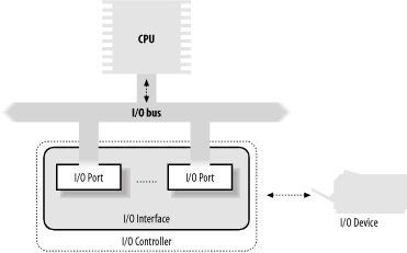
When the bus connects the CPU to an I/O device, it is called an I/O bus . In this case, 80 × 86 microprocessors use 16 out of the 32 address lines to address I/O devices and 8, 16, or 32 out of the 64 data lines to transfer data. The I/O bus, in turn, is connected to each I/O device by means of a hierarchy of hardware components including up to three elements: I/O ports, interfaces, and device controllers. Figure 13-1 shows the components of the I/O architecture.
Each device connected to the I/O bus has its own set of I/O
addresses, which are usually called I/O ports
. In the IBM PC architecture, the I/O
address space provides up to 65,536 8-bit I/O ports. Two consecutive
8-bit ports may be regarded as a single 16-bit port, which must start
on an even address. Similarly, two consecutive 16-bit ports may be
regarded as a single 32-bit port, which must start on an address that
is a multiple of 4. Four special assembly language instructions
called in, ins,
out, and outs allow the CPU to
read from and write into an I/O port. While executing one of these
instructions, the CPU uses the address bus to select the required I/O
port and of the data bus to transfer data between a CPU register and
the port.
I/O ports may also be mapped into addresses of the physical address
space. The processor is then able to communicate with an I/O device
by issuing assembly language instructions that operate directly on
memory (for instance, mov, and,
or, and so on). Modern hardware devices are more
suited to mapped I/O, since it is faster and can be combined with
DMA.
An important objective for system designers is to offer a unified approach to I/O programming without sacrificing performance. Toward that end, the I/O ports of each device are structured into a set of specialized registers, as shown in Figure 13-2. The CPU writes the commands to be sent to the device into the control register and reads a value that represents the internal state of the device from the status register . The CPU also fetches data from the device by reading bytes from the input register and pushes data to the device by writing bytes into the output register .

To lower costs, the same I/O port is often used for different purposes. For instance, some bits describe the device state, while others specify the command to be issued to the device. Similarly, the same I/O port may be used as an input register or an output register.
The in, out,
ins, and outs assembly language
instructions access I/O ports. The following auxiliary functions are
included in the kernel to simplify such accesses:
-
inb( ),inw( ),inl( ) Read 1, 2, or 4 consecutive bytes, respectively, from an I/O port. The suffix “b,” “w,” or “l” refers, respectively, to a byte (8 bits), a word (16 bits), and a long (32 bits).
-
inb_p( )inw_p( ),inl_p( ) Read 1, 2, or 4 consecutive bytes, respectively, from an I/O port, and then execute a “dummy” instruction to introduce a pause.
-
outb( ),outw( ),outl( ) Write 1, 2, or 4 consecutive bytes, respectively, to an I/O port.
-
outb_p( ),outw_p( ),outl_p( ) Write 1, 2, and 4 consecutive bytes, respectively, to an I/O port, and then execute a “dummy” instruction to introduce a pause.
-
insb( ),insw( ),insl( ) Read sequences of consecutive bytes in groups of 1, 2, or 4, respectively, from an I/O port. The length of the sequence is specified as a parameter of the functions.
-
outsb( ),outsw( ),outsl( ) Write sequences of consecutive bytes, in groups of 1, 2, or 4, respectively, to an I/O port.
While accessing I/O ports is simple, detecting which I/O ports have been assigned to I/O devices may not be easy, in particular, for systems based on an ISA bus. Often a device driver must blindly write into some I/O port to probe the hardware device; if, however, this I/O port is already used by some other hardware device, a system crash could occur. To prevent such situations, the kernel keeps track of I/O ports assigned to each hardware device by means of “resources.”
A resource
represents a portion of some entity that can be exclusively assigned
to a device driver. In our case, a resource represents a range of I/O
port addresses. The information relative to each resource is stored
in a resource data structure, whose fields are
shown in Table 13-1. All resources of the same kind
are inserted in a tree-like data structure; for instance, all
resources representing I/O port address ranges are included in a tree
rooted at the node ioport_resource.
Table 13-1. The fields of the resource data structure
|
Type |
Field |
Description |
|---|---|---|
|
|
|
Description of owner of the resource |
|
|
|
Start of the resource range |
|
|
|
End of the resource range |
|
|
|
Various flags |
|
|
|
Pointer to parent in the resource tree |
|
|
|
Pointer to a sibling in the resource tree |
|
|
|
Pointer to first child in the resource tree |
The children of a node are collected in a list whose first element is
pointed to by the child field. The
sibling field points to the next node in the list.
Why use a tree? Well, consider, for instance, the I/O port addresses
used by an IDE hard disk interface—let’s say
from 0xf000 to 0xf00f. A
resource with the start field set to
0xf000 and the end field set to
0xf00f is then included in the tree, and the
conventional name of the controller is stored in the
name field. However, the IDE device driver needs
to remember another bit of information, namely that the subrange from
0xf000 to 0xf007 is used for
the master disk of the IDE chain, while the subrange from
0xf008 to 0xf00f is used for
the slave disk. To do this, the device driver inserts two children
below the resource corresponding to the whole range from
0xf000 to 0xf00f, one child for
each subrange of I/O ports. As a general rule, each node of the tree
must correspond to a subrange of the range associated with the
parent.
Any device driver may use the following three functions, passing to them the root node of the resource tree and the address of a resource data structure of interest:
-
request_resource( ) Assigns a given range to an I/O device.
-
check_resource( ) Checks whether a given range is free or whether some subrange has already been assigned to an I/O device
-
release_resource( ) Releases a given range previously assigned to an I/O device.
The kernel also defines some shortcuts to the above functions that
apply to I/O ports: request_region( ) assigns a
given interval of I/O ports, check_region( )
verifies whether a given interval of I/O ports is free or (even
partially) busy, and release_region( ) releases a
previously assigned interval of I/O ports. The tree of all I/O
addresses currently assigned to I/O devices can be obtained from the
/proc/ioports file.
An I/O interface is a hardware circuit inserted between a group of I/O ports and the corresponding device controller. It acts as an interpreter that translates the values in the I/O ports into commands and data for the device. In the opposite direction, it detects changes in the device state and correspondingly updates the I/O port that plays the role of status register. This circuit can also be connected through an IRQ line to a Programmable Interrupt Controller, so that it issues interrupt requests on behalf of the device.
There are two types of interfaces:
- Custom I/O interfaces
Devoted to one specific hardware device. In some cases, the device controller is located in the same card [89] that contains the I/O interface. The devices attached to a custom I/O interface can be either internal devices (devices located inside the PC’s cabinet) or external devices (devices located outside the PC’s cabinet).
- General-purpose I/O interfaces
Used to connect several different hardware devices. Devices attached to a general-purpose I/O interface are always external devices.
Just to give an idea of how much variety is encompassed by custom I/O interfaces — thus by the devices currently installed in a PC — we’ll list some of the most commonly found:
- Keyboard interface
Connected to a keyboard controller that includes a dedicated microprocessor. This microprocessor decodes the combination of pressed keys, generates an interrupt, and puts the corresponding scan code in an input register.
- Graphic interface
Packed together with the corresponding controller in a graphic card that has its own frame buffer , as well as a specialized processor and some code stored in a Read-Only Memory chip (ROM). The frame buffer is an on-board memory containing a description of the current screen contents.
- Disk interface
Connected by a cable to the disk controller, which is usually integrated with the disk. For instance, the IDE interface is connected by a 40-wire flat conductor cable to an intelligent disk controller that can be found on the disk itself.
- Bus mouse interface
Connected by a cable to the corresponding controller, which is included in the mouse.
- Network interface
Packed together with the corresponding controller in a network card used to receive or transmit network packets. Although there are several widely adopted network standards, Ethernet (IEEE 802.3) is the most common.
Modern PCs include several general-purpose I/O interfaces, which connect a wide range of external devices. The most common interfaces are:
- Parallel port
Traditionally used to connect printers, it can also be used to connect removable disks, scanners, backup units, and other computers. The data is transferred 1 byte (8 bits) at a time.
- Serial port
Like the parallel port, but the data is transferred 1 bit at a time. It includes a Universal Asynchronous Receiver and Transmitter (UART) chip to string out the bytes to be sent into a sequence of bits and to reassemble the received bits into bytes. Since it is intrinsically slower than the parallel port, this interface is mainly used to connect external devices that do not operate at a high speed, like modems, mouses, and printers.
- Universal serial bus (USB)
A recent general-purpose I/O interface that is quickly gaining popularity. It operates at a high speed, and may be used for the external devices traditionally connected to the parallel port and the serial port.
- PCMCIA interface
Included mostly on portable computers. The external device, which has the shape of a credit card, can be inserted into and removed from a slot without rebooting the system. The most common PCMCIA devices are hard disks, modems, network cards, and RAM expansions.
- SCSI (Small Computer System Interface) interface
A circuit that connects the main PC bus to a secondary bus called the SCSI bus . The SCSI-2 bus allows up to eight PCs and external devices—hard disks, scanners, CD-ROM writers, and so on—to be connected. Wide SCSI-2 and the recent SCSI-3 interfaces allow you to connect 16 devices or more if additional interfaces are present. The SCSI standard is the communication protocol used to connect devices via the SCSI bus.
A complex device may require a device controller to drive it. Essentially, the controller plays two important roles:
It interprets the high-level commands received from the I/O interface and forces the device to execute specific actions by sending proper sequences of electrical signals to it.
It converts and properly interprets the electrical signals received from the device and modifies (through the I/O interface) the value of the status register.
A typical device controller is the disk controller , which receives high-level commands such as a “write this block of data” from the microprocessor (through the I/O interface) and converts them into low-level disk operations such as “position the disk head on the right track” and “write the data inside the track.” Modern disk controllers are very sophisticated, since they can keep the disk data in fast memory caches and can reorder the CPU high-level requests optimized for the actual disk geometry.
Simpler devices do not have a device controller; examples include the Programmable Interrupt Controller (see Section 4.2) and the Programmable Interval Timer (see Section 6.1.3).
Several hardware devices include their own memory, which is often called I/O shared memory . For instance, all recent graphic cards include a few megabytes of RAM in the frame buffer, which is used to store the screen image to be displayed on the monitor.
Depending on the device and on the bus type, I/O shared memory in the PC’s architecture may be mapped within three different physical address ranges:
- For most devices connected to the ISA bus
The I/O shared memory is usually mapped into the physical addresses ranging from
0xa0000to0xfffff; this gives rise to the “hole” between 640 KB and 1 MB mentioned in Section 2.5.3.- For some old devices using the VESA Local Bus (VLB)
This is a specialized bus mainly used by graphic cards: the I/O shared memory is mapped into the physical addresses ranging from
0xe00000to0xffffff—that is, between 14 MB and 16 MB. These devices, which further complicate the initialization of the paging tables, are going out of production.- For devices connected to the PCI bus
The I/O shared memory is mapped into very large physical addresses, well above the end of RAM’s physical addresses. This kind of device is much simpler to handle.
Recently, Intel introduced the Accelerated Graphics Port (AGP) standard, which is an enhancement of PCI for high-performance graphic cards. Beside having its own I/O shared memory, this kind of card is capable of directly addressing portions of the motherboard’s RAM by means of a special hardware circuit named Graphics Address Remapping Table (GART). The GART circuitry enables AGP cards to sustain much higher data transfer rates than older PCI cards. From the kernel’s point of view, however, it doesn’t really matter where the physical memory is located, and GART-mapped memory is handled like the other kinds of I/O shared memory.
How does the kernel access an I/O shared memory location? Let’s start with the PC’s architecture, which is relatively simple to handle, and then extend the discussion to other architectures.
Remember that kernel programs act on linear addresses, so the I/O
shared memory locations must be expressed as addresses greater than
PAGE_OFFSET. In the following discussion, we
assume that PAGE_OFFSET is equal to
0xc0000000 — that is, that the kernel linear
addresses are in the fourth gigabyte.
Kernel drivers must translate I/O physical addresses of I/O shared
memory locations into linear addresses in kernel space. In the PC
architecture, this can be achieved simply by ORing the 32-bit
physical address with the 0xc0000000 constant. For
instance, suppose the kernel needs to store the value in the I/O
location at physical address 0x000b0fe4 in
t1 and the value in the I/O location at physical
address 0xfc000000 in t2 . One
might think that the following statements could do the job:
t1 = *((unsigned char *)(0xc00b0fe4));
t2 = *((unsigned char *)(0xfc000000));
During the initialization phase, the kernel maps the available
RAM’s physical addresses into the initial portion of
the fourth gigabyte of the linear address space. Therefore, the
Paging Unit maps the 0xc00b0fe4 linear address
appearing in the first statement back to the original I/O physical
address 0x000b0fe4, which falls inside the
“ISA hole” between 640 KB and 1 MB
(see Section 2.5). This works fine.
There is a problem, however, for the second statement because the I/O
physical address is greater than the last physical address of the
system RAM. Therefore, the 0xfc000000 linear
address does not necessarily correspond to the
0xfc000000 physical address. In such cases, the
kernel Page Tables must be modified to include a linear address that
maps the I/O physical address. This can be done by invoking the
ioremap( ) or ioremap_nocache( ) functions. These functions, which are similar to
vmalloc( ), invoke get_vm_area( ) to create a new vm_struct descriptor
(see Section 7.3.2) for a linear address
interval that has the size of the required I/O shared memory area.
The functions then updates the corresponding Page Table entries of
the canonical kernel Page Tables appropriately.
ioremap_nocache( ) differs from ioremap( ) in that it also disables the hardware cache when
referencing the remapped linear addresses properly.
The correct form for the second statement might therefore look like:
io_mem = ioremap(0xfb000000, 0x200000);
t2 = *((unsigned char *)(io_mem + 0x100000));
The first statement creates a new 2 MB linear address interval, which
maps physical addresses starting from 0xfb000000;
the second one reads the memory location that has the
0xfc000000 address. To remove the mapping later,
the device driver must use the iounmap( )
function.
On some architectures other than the PC, I/O shared memory cannot be accessed by simply dereferencing the linear address pointing to the physical memory location. Therefore, Linux defines the following architecture-dependent macros, which should be used when accessing I/O shared memory:
-
readb,readw,readl Reads 1, 2, or 4 bytes, respectively, from an I/O shared memory location
-
writeb,writew,writel Writes 1, 2, or 4 bytes, respectively, into an I/O shared memory location
-
memcpy_fromio,memcpy_toio Copies a block of data from an I/O shared memory location to dynamic memory and vice versa
-
memset_io Fills an I/O shared memory area with a fixed value
The recommended way to access the 0xfc000000 I/O
location is thus:
io_mem = ioremap(0xfb000000, 0x200000);
t2 = readb(io_mem + 0x100000);
Thanks to these macros, all dependencies on platform-specific ways of accessing the I/O shared memory can be hidden.
All PCs include an auxiliary processor called the Direct Memory Access Controller (DMAC), which can be instructed to transfer data between the RAM and an I/O device. Once activated by the CPU, the DMAC is able to continue the data transfer on its own; when the data transfer is completed, the DMAC issues an interrupt request. The conflicts that occur when both CPU and DMAC need to access the same memory location at the same time are resolved by a hardware circuit called a memory arbiter (see Section 5.3.1).
The DMAC is mostly used by disk drivers and other slow devices that transfer a large number of bytes at once. Because setup time for the DMAC is relatively high, it is more efficient to directly use the CPU for the data transfer when the number of bytes is small.
The first DMACs for the old ISA buses were complex, hard to program, and limited to the lower 16 MB of physical memory. More recent DMACs for the PCI and SCSI buses rely on dedicated hardware circuits in the buses and make life easier for device driver developers.
Until now we have distinguished three kinds of memory addresses: logical and linear addresses, which are used internally by the CPU, and physical addresses, which are the memory addresses used by the CPU to physically drive the data bus. However, there is a fourth kind of memory address: the so-called bus address . It corresponds to the memory addresses used by all hardware devices except the CPU to drive the data bus. In the PC architecture, bus addresses coincide with physical addresses; however, in other architectures (like Sun’s SPARC and Hewlett-Packard’s Alpha), these two kinds of addresses differ.
Why should the kernel be concerned at all about bus addresses? Well, in a DMA operation, the data transfer takes place without CPU intervention; the data bus is driven directly by the I/O device and the DMAC. Therefore, when the kernel sets up a DMA operation, it must write the bus address of the memory buffer involved in the proper I/O ports of the DMAC or I/O device.
Several I/O drivers use the Direct Memory Access Controller (DMAC) to speed up operations. The DMAC interacts with the device’s I/O controller to perform a data transfer and the kernel includes an easy-to-use set of routines to program the DMAC. The I/O controller signals to the CPU, via an IRQ, when the data transfer has finished.
When a device driver sets up a DMA operation for some I/O device, it
must specify the memory buffer involved by using bus addresses. The
kernel provides the virt_to_bus and
bus_to_virt macros, respectively, to translate a
linear address into a bus address and vice versa.
As with IRQ lines, the DMAC is a resource that must be assigned dynamically to the drivers that need it. The way the driver starts and ends DMA operations depends on the type of bus.
For recent buses, such as PCI or SCSI, there are two main steps to
perform: allocating an IRQ line and triggering the DMA transfer. The
IRQ line used for signaling the termination of the DMA operation is
allocated when opening the device file (see the later section Section 13.3.4). To start a DMA operation,
the device driver simply writes the bus address of the DMA buffer,
the transfer direction, and the size of the data in an I/O port of
the hardware device; the driver then suspends the current process.
When the DMA transfer ends, the hardware device raises an interrupt
that wakes the device driver. The release method
of the device file releases the IRQ line when the file object is
closed by the last process.
[89] Each card must be inserted in one of the available free bus slots of the PC. If the card can be connected to an external device through an external cable, the card sports a suitable connector in the rear panel of the PC.