
Microemulsions for Cleaning Applications
Lirio Quintero, Baker Hughes, Houston, TX, USA
Norman F. Carnahan, Carnahan Corporation, Houston, TX, USA
Chapter Outline
2. Types of Microemulsions, Formulations and Properties
2.1.1. Selection of Surfactant
2.2. Properties of Microemulsions
2.2.3. Contact Angle and Wettability
3. Basic Process and Principles of Cleaning Surfaces
4. Surface Cleaning and Contaminant Removal with Microemulsions
5. Design of Microemulsion Cleaners and Evaluation Techniques
6. Microemulsion Cleaning Applications
6.1. Cleaning of Oil-Contaminated Drill Cuttings
6.2. Wellbore Cleanup During Displacement of Oil-Based Drilling Fluids to Water-Based Fluid
6.3. Near-Wellbore Cleaning in Oil and Gas Wells
6.3.1. Removal of Oil-Based Fluid Filter Cake in OH Completion Wells
6.3.2. Removal of Formation Damage in CH Completion Wells
6.4. Other Cleaning Applications
6.4.1. Wastewater Cleaning and Microemulsion Froth Flotation
6.4.2. Microemulsion Cleaning of Contaminated Soil and Groundwater
6.4.3. Microemulsion Cleaning of Textiles
6.4.4. Microemulsion Cleaning Using Nonaqueous Solvents
6.4.5. Microemulsion Cleaning of Building Exteriors
6.4.6. Microemulsion Cleaning of Frescoes and Artwork
6.4.7. Microemulsion Cleaning of Crude Oil Reservoirs
6.4.8. Microemulsion Cleaning of Fracturing Gels from Shale and Other Rock Formations
1 Introduction
Since microemulsions were first described by Schulman et al. [1,2], the interest of researchers in studying their phase behavior, formulations, properties, fundamental mechanisms and applications has progressively grown. Salager reported that an exponential growth in microemulsion publications surpassed 1000 in 2003 [3]. This number keeps growing, with a considerable number of publications on microemulsion applications in recent years. Projecting the Salager-Schulman estimate, the number of microemulsion publications would be about 3200 in 2013, and around 7000 in 2020.
Microemulsions are thermodynamically stable, translucent fluids consisting of microdomains of oil and/or water stabilized by an interfacial film of surfactant molecules [4–8]. These systems may include optional additives such as cosurfactants, acids, lipophilic and hydrophilic linkers. Due to the importance of microemulsions in cleaning applications for various industries, their phase behavior and properties have been and continue to be studied extensively.
The ultralow interfacial tensions (IFTs) between oil and aqueous phases and the solubilization characteristics encountered in microemulsion systems make them useful for a wide variety of applications. Microemulsions are used in applications such as cleaning of surfaces, detergent applications, improved crude oil recovery, liquid–liquid extractions, pharmaceuticals and cosmetic formulations.
This chapter presents a comprehensive discussion on microemulsions for surface cleaning.
2 Types of Microemulsions, Formulations and Properties
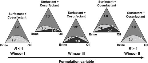
Microemulsions are classified into three categories according to Winsor’s phase behavior studies [9]. Winsor I microemulsion systems consist of oil-swollen micelles in a water phase in equilibrium with excess oil. Winsor II microemulsion systems consist of water-swollen reverse micelles in an oil phase in equilibrium with excess water. Winsor III systems are a middle-phase bicontinuous microemulsion in equilibrium with excess water and oil. The surfactant(s) in the bicontinuous microemulsions have equal affinity for the water phase and the oil phase. A single-phase microemulsion (Winsor IV) is obtained when a sufficient amount of surfactant is added to a Winsor III system to solubilize the excess oil and water into the microemulsion [4,5].
2.1 Formulations
The success of microemulsions as cleaners depends on the proper selection of additives in formulating the microemulsion fluid. Selection of the best fluid formulations requires systematic studies of phase behavior of the microemulsion systems. These studies include variables such as the type and concentration of surfactant, cosurfactant, salt, lipophilic linker, hydrophilic linker and solvent or oil, as well as temperature. Pressure has minimal or no effect except in cases where one of the components is compressible, e.g. systems involving supercritical fluids.
The phase behavior of water–surfactant–oil systems is typically studied by preparing a series of vials in which only one variable is progressively changed. For example, in a phase behavior study as a function of the concentration of sodium chloride (NaCl) salt, the percentage of NaCl is increased in each vial and the proportions of the remaining components of the system (surfactant, cosurfactant, aqueous phase, and oil) are maintained constant.
Figure 2.1 shows an example of Winsor phase behavior that could be obtained for oil–water–surfactant systems when the aforementioned variables are systematically changed. The phase behavior shows the characteristic progression from two-phase to three-phase to two-phase coexistence of an oil–water–surfactant system with the oil/water ratio, surfactant and cosurfactant concentrations constant and progressive increase of the salinity of the aqueous phase. At low salinity, a microemulsion coexists with an excess of oil (Winsor I). At high salinity, a microemulsion coexists with an excess of brine (Winsor II). At intermediate salinities, a bicontinuous microemulsion coexists with an excess of water phase and oil phase [9–12].

The data obtained from phase behavior studies are used to build the phase diagrams, enabling better understanding of capabilities and possible performance of the fluid formulated with a particular brine–surfactant–oil system.
Winsor introduced the concept of ratio of interactions (R) between the surfactant, oil, and water phases to determine the convexity of the interface and the resulting phase behavior [13].
![]() (2.1)
(2.1)
The term ASO represents the interaction energy between the surfactant and the oil. ASW is the interaction energy between the surfactant and the aqueous phase, AOO, the interaction energy between oil molecules, AWW, the interaction energy between water molecules, ATT, the interaction energy between the tails of the surfactant molecules, and AHH, the interaction energy between the surfactant heads.
If the surfactant molecules at the interface have stronger interactions with the water phase than the oil phase, ASW is greater than ASO and the term R is less than one. In this case, the interface shows a curvature toward the oil. The reverse effect (where R is greater than one) is observed when ASO is greater than ASW. In the case of equal interaction, R is equal to one. This means the interfacial curvature is near zero, which corresponds to the bicontinuous microemulsion structure described by various authors. Figure 2.2 shows an example of phase diagrams obtained with the phase behavior data of a brine–surfactant–oil system, as the ratio of interactions changes from R < 1 to R > 1.
There are various empirical correlations used to explain the physical chemistry of the formulations prepared in a phase behavior study. Salager et al. [14] described the experimental technique to identify the optimal formulation in a phase behavior or formulation scan study. The optimum formulation in a series of vials of the phase behavior evaluation corresponds to the value of the variable with the three phases (Winsor III) that show equal volumes of oil and water solubilized. Equations (2.2) and (2.3) show the empirical correlation for the optimum formulation obtained for anionic surfactants and nonionic surfactants, respectively [14–20].
![]() (2.2)
(2.2)
![]() (2.3)
(2.3)
where,
S is the optimum salinity of the microemulsion system, expressed in wt% NaCl with respect to the aqueous phase
K is a constant for a given surfactant that depends on the type of surfactant head group
ACN is the linear alkane carbon number of the oil (for a nonlinear hydrocarbon oil or for a nonhydrocarbon oil it becomes the equivalent alkane carbon number, EACN)
f(A) and ϕ(A) are functions of the alcohol/cosurfactant type and concentration
σ and α are the parameters that are functions of surfactant structure
aT is a constant (∼0.01 when temperature is in Celsius)
T is the temperature of evaluation
Tref is a reference temperature
EON is the average number of ethylene oxide group per molecule of nonionic surfactant
b, k, aT and cT are the empirical constants that depend on the type of system.
These empirical correlations are actually numerical expressions of the surfactant affinity difference (SAD) used to interpret the formulation parameters of microemulsions [5,21,22]. The SAD expression represents the difference between the chemical potential of the surfactant in the aqueous phase and the oil phase as a function of different formulation parameters, as follows in Eqns (2.4) and (2.5) for anionic surfactants and for nonionic surfactants, respectively.
![]() (2.4)
(2.4)
![]() (2.5)
(2.5)
SAD can be negative, zero or positive. The optimum formulation is found where SAD is equal to zero. When the formulation has a deviation from the SAD = 0 condition, it can be modified to reach the optimum formulation by changing the physicochemical conditions (change the variables). Similar to the Winsor R ratio, the magnitude of the SAD value measures the departure from the optimum formulation. SAD < 1, SAD = 0 or SAD > 1 suggest the formation of Winsor Type I, Type III or Type II microemulsions, respectively.
Salager et al. proposed an empirical correlation known as the hydrophilic–lipophilic deviation (HLD) as a dimensionless form of the thermodynamically derived SAD equation to describe microemulsion systems [23,24]. In this case, negative-, zero-, or positive-HLD values suggest the formation of Winsor Type I, Type III or Type II microemulsions, respectively.
The general HLD equations for anionic and nonionic surfactants are Eqns (2.6) and (2.7), respectively [20,23]:
![]() (2.6)
(2.6)
![]() (2.7)
(2.7)
HLD is equal to zero at the optimum formulation because there is no difference between the hydrophilic and lipophilic interaction energies.
2.1.1 Selection of Surfactant
The selection of surfactant(s) for microemulsions depends on the requirements of specific applications. Microemulsions for cleaning applications (where variables such as temperature, type and density of brine, type of surface, and type of dirt or contaminant to be cleaned are considered in the design) usually require combinations of surfactants. The selection includes surfactants that provide very low IFT, surfactants that act as hydrotopes to improve solubilization, and surfactant molecules for cleaning product uses at high or low temperature. In some cases, surfactants for formulations containing acids or alkali substances are needed.
2.1.2 Effect of Salinity
Scans of formulations are carried out using salts (e.g. potassium chloride, sodium chloride, calcium chloride, or calcium bromide) for the specific oil–water–surfactant systems used in microemulsion formulations. Studies of systems formulated with anionic surfactants exhibit a more significant salinity effect than systems formulated with nonionic surfactants. However, salinity also has an effect on nonionic surfactants. In the case of microemulsion systems with anionic surfactants, the addition of salts causes significant changes in the phase behavior of water–surfactant and oil–water–surfactant with addition of salts. The “optimal salinity” in the phase behavior of these systems is defined as the salinity at which a middle-phase microemulsion solubilizes equal amounts of oil and brine [25–27]. However, solubilization decreases for salinities higher than optimal salinity due to increased interfacial rigidity and curvature [28,29]. The existence of middle-phase microemulsions in equilibrium with excess oil and brine has been attributed to attractive interdroplet interaction and interfacial bending stress [28,30–32]. The highest efficiency of the microemulsion systems used to clean oily or dirty surfaces occurs at the salinity where the system reaches the minimum IFT and maximum solubilization.
2.1.3 Effect of Cosurfactant
In addition to the surfactants, substances such as alcohols can be used to act as cosurfactants to fine-tune or adjust the phase behavior of the brine–surfactant–oil systems to bring the microemulsion into the required experimental window of composition and temperature.
Addition of a short-chain alcohol (e.g. isopropanol and n-butanol) as a cosurfactant can increase the total interfacial area at low alcohol concentrations, thus increasing the solubilization [10,33] and decreasing the IFT. Figure 2.3(a) shows the dynamic IFT between the aqueous and oil phases used in a microemulsion formulation. One formulation is without alcohol and two formulations have a short-chain alcohol as cosurfactant. The results show that the IFT decreases with increasing length of the alcohol chain for this particular microemulsion system. The two formulations with cosurfactants show very low IFT from the initial contact with oil. The increase in short-chain alcohol concentration in the microemulsion system also reduce the IFT with time, as is shown in Fig. 2.3(b). Conversely, at high alcohol concentrations, phase separation occurs due to the increase in attractive interdroplet interaction. For this reason, only an optimal amount of alcohol is desired to formulate a microemulsion with maximum solubilization capacity. Increase of the alcohol chain length makes the system more lipophilic and reduces the attractive interdroplet interaction. The addition of an optimal amount of alcohol and salinity, together with the effect of the composition of the oil phase, may lead to the highest possible solubilization capacity of a given microemulsion.

2.1.4 Effect of Linkers
Lipophilic and/or hydrophilic linker additives could be used to increase the solubilization and modify the interfacial properties of the microemulsion [34–39]. These are amphiphilic molecules that segregate near the oil/water interface, near the hydrophobic surfactant tail (lipophilic linkers) or the surfactant head group (hydrophilic linkers) [34].
The lipophilic linkers are defined as molecules that, while present in the oil phase, orient along the surfactant tails and promote orientation of oil molecules further into the oil phase. The addition of a hydrophilic linker increases the space between surfactant molecules, a enabling flexible surfactant membrane, that leads to faster coalescence and solubilization kinetics [3]. Lipophilic linkers thus serve as a link between oil molecules and the surfactant tails [3,35,36]. Examples of lipophilic linkers are long-chain alcohols, such as alcohols with more than eight carbons. These molecules act as lipophilic linkers in microemulsion systems because they have an increased interaction with the oil molecules but do not adsorb at the interface. For alcohols having between four and eight carbons, the alcohols behave as cosurfactants because they interact strongly with the oil but retain their adsorption at the oil–water interface. Small alcohols with less than four carbons show a cosolvent effect that helps decrease the surfactant–surfactant interaction.
The concept of hydrophilic linker was introduced later by adding a surfactant-like molecule that segregates near or at the oil/water interface, but due to its short tail offers little interaction with the oil phase [38].
Combinations of hydrophilic and lipophilic linkers can produce a surfactant-like system. The proper combination of lipophilic and hydrophilic linkers has been found to significantly increase the solubilization capacity for different oils [34,38,40]. The linker approach has been used to formulate microemulsions in applications such as environmental remediation and detergent formulations [41,42].
The linker molecules tend to extend the thickness of the interfacial zone over which the transition from polar to nonpolar phase takes place. The problem of the linker additives is that there is sometimes a need to add a large excess in order to have enough of it at the right place. This is a fractionation effect that results from the fact that very different molecules are likely to move where they find a better physicochemical environment [3,43].
Once the solubilization enhancement with linkers was understood, researchers started to work on synthesizing surfactants with spacer arms between the hydrophilic head and lipophilic chain to produce similar solubilization behavior compared with the combination of surfactants with linkers. These surfactants are called extended surfactants. In general, these molecules are longer than conventional surfactants and exhibit increased contact on both sides of the interface. However, if these molecules are too long, precipitation could occur. Examples of these molecules are alcohol ethoxylated propoxylated sulfates and alcohol ethoxylated propoxylated carboxylates [43–47].
2.1.5 Type of Oil or Solvent
The type and chemical composition of the oil and/or solvent used in microemulsion systems considerably influence their phase behavior and properties. When the oil molecules are solubilized in the aggregated core of the micelles, the micelles become swollen and their surface curvature tends to decrease, producing changes in the phase behavior [4,20]. The interaction between the oil molecules and the surfactant hydrophobic tail is a key parameter that must be considered in the selection of appropriate surfactants to obtain the desired microemulsion formulation.
In general, the oil and/or solvents are not alkanes composed of a single type of molecule. They are blends of molecules with a distribution of molecular weights and molecular configurations. Additionally, the oil and/or solvent can have a variety of chemical compositions that can be used in formulation and applications of microemulsions. In this case the EACN is used instead [15]. The EACN of an oil mixture can be deduced from its composition by a linear mixing rule based on molar fraction. The EACN of many oils has been measured [20]. The EACN concept is a very useful tool in the studies of microemulsion formulations. The EACN of an oil is a dimensionless number that reflects the “hydrophobicity” of oil. It is determined experimentally by comparing its phase behavior with that of a well-defined linear hydrocarbon in the same surfactant–oil–water system [5,14–16,48]. The EACN of a linear alkane is simply its carbon number. For example, the EACN of n-heptane and n-decane and n-dodecane are 7, 10 and 12, respectively. Oil molecules containing polar groups have low EACN because the presence of a polar group in the oil molecule reduces its EACN. Examples are ethyl oleate and C16–C18 triglyceride that have EACN of around 6 [5].
2.1.6 Temperature Effect
Temperature is an important variable that affects the performance of systems containing surfactants. The effect of changes in temperature on the phase behavior of surfactants in solution is very complex. The size of the micelles and the type of surfactant association change with temperature and affect the phase behavior of surfactant–water or surfactant–oil–water systems. Anionic surfactants typically become more hydrophilic as temperature increases, whereas nonionic surfactants present the opposite trend [49]. In the case of microemulsion systems formulated with only nonionic surfactants, the interaction between the hydrophilic part of the molecule and water increases as temperature decreases. For example, an increase in temperature or a decrease in ethylene oxide composition of the surfactant molecule has similar effects on formulations. In formulations with nonionic surfactants, their temperature effect is explained by the fact that the solubility of nonionic surfactants in water is due to hydrogen bonding, which is a very sensitive function of the temperature. Thus, increasing temperature may be expected to have a similar effect as increasing salinity [19,50,51].
To overcome the thermal sensitivity of the microemulsion formulations with either nonionic or anionic surfactants, a proper blend of anionic and nonionic surfactants could produce formulations with minimum sensitivity to temperature [49,51].
Another option to obtain thermally stable microemulsion formulations for applications at elevated temperatures, especially for temperatures higher than 150 °C, is to blend cationic surfactants with nonionic surfactants because some of these combinations exhibit excellent synergistic effects.
2.2 Properties of Microemulsions
2.2.1 Solubilization
Microemulsions solubilize immiscible water and oil systems. Solubilization in microemulsions results from the equilibrium coexistence of oil and water in the presence of surfactants and cosurfactants that form swollen micelles.
The increase of interactions between surfactant and oil and surfactant in water in a microemulsion system increases their solubilization. This can be quantified by obtaining the solubilization parameter (SP). The solubilization parameter is the amount of oil solubilized in the core of the swollen micelles per unit mass of surfactant [3]. An alternative option to measure solubilization is to measure the minimum amount of surfactant necessary to produce a single phase in a surfactant–oil–water system. The curvature of the micelles decreases as the oil solubilization in the core of the micelles increases, up to a point where the HLD is zero or Winsor R is equal to one [3,20].
The solubilization capacity of microemulsion systems could be increased by using lipophilic linkers, hydrophilic linkers and/or extended surfactant molecules [3]. This approach is very attractive for many applications, including surface cleaning applications.
2.2.2 Interfacial Tension
The reduction of IFT between the aqueous phase and the oil phase is important in the selection of additives to formulate the aqueous solution to maximize cleaning and water-wetting efficiency. The magnitude of IFT will be dictated by the addition of surfactant(s), cosurfactants and linkers over a range of compositions and temperatures corresponding to expected application conditions.
It is well established that very low IFT plays an important role in the cleaning efficiency and in oil removal from solid surfaces [52–54]. Selection of proper surfactants that reduce the IFT between the aqueous and oil phases plays a significant role in the overall effectiveness and ability of any fluid system to clean and perform in a prescribed environment [30].
Figure 2.4 shows an example of the dynamic IFT between mineral oil and the aqueous phase used in a microemulsion formulation for cleaning oil-based drilling fluids measured at 60 °C with a spinning drop tensiometer. The results presented in Fig. 2.4 show that when the surfactant–water system contacted the oil phase, the IFT dropped to 0.5 mN/m. Figure 2.4 also shows the IFT between the same oil and water as a point of comparison.

FIGURE 2.4 Interfacial tension of system used in microemulsion formulations for cleaning oily surfaces contaminated with oil-based drilling fluids.
Another way to obtain the IFT is by using the theoretical relationship between solubilization ratios and IFT derived by Huh [55], which predicts that the IFT is inversely proportional to the square of the solubilization ratio at equilibrium. This approach enables the determination of the IFT without the need to measure IFT experimentally.
In a surfactant–water–oil system, IFT passes through a minimum and the solubilization parameter reaches a maximum at the optimum formulation condition. The minimum value of IFT and maximum value of SP define the characteristics of an optimum system. These enable one to compare different systems from an overall point of view [5,21].
2.2.3 Contact Angle and Wettability
The wettability of a surface is a characteristic that affects cleaning effectiveness, fluid displacement and solids mobilization. The contact angle of a water droplet on a surface, before and after exposure to different fluids, is an important consideration in evaluating a microemulsion cleaning fluid. When a liquid droplet is placed in contact with a flat solid surface, two distinct equilibrium regimes may occur: partial wetting with a finite contact angle (θ) and complete wetting (θ = 0) [56]. Contact angle measurements are used to evaluate the ability of the fluids to change the surface wettability from oil-wet to water-wet and vice versa.
The determination of the equilibrium contact angle, described in Young’s equation [57], requires very clean experimental conditions and depends on the liquid surface tension, the surface free energy of the solid and the interaction between the solid and liquid materials [56–58]. A deviation from the thermodynamic equilibrium condition results in contact angle hysteresis, which is observed by an advancing angle when the solid/liquid contact area increases and a receding angle when the contact area shrinks [56].
When microemulsion fluids contact solid surfaces, the interfacial free energy of the liquid–solid interface decreases, resulting in a reduction of the contact angle between the solid surface and the microemulsion. Figure 2.5(a) and (b) is the schematic description of this phenomenon showing the contact angles encountered in an oil-wet surface and a water-wet surface, respectively. If the oil-wet surface is exposed to a microemulsion cleaning fluid, the oily material is removed and the wettability changes from oil-wet to water-wet (the contact angle for the water is significantly reduced).

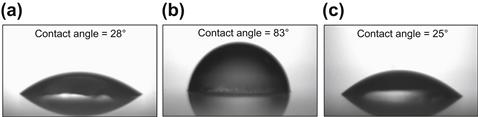
For practical applications, it is recommended that the contact angle measurement should be analyzed as a relative measurement compared to a baseline. One practical test procedure is to analyze the measured contact angle data as a measurement relative to a baseline of a clean, untreated glass slide. Figure 2.6(a) shows that the clean glass slide has a contact angle of 28° with the water. Then, to simulate contact of oily material or other nonaqueous fluid, the glass slide is exposed to oil containing oil-wetting surfactants for 10 minutes. The contact angle of the water, now 83° (Fig. 2.6(b)), is much higher than the native surface, thus proving that the previously water-wet surface has been transformed to an oil-wet state after exposure to the oil-based fluid. Finally, the oil-wet surface is exposed to the microemulsion cleaner fluid for 10 minutes, resulting in a water contact angle of 25° as observed in Fig. 2.6(c). The surface has returned to its initial water-wet state. These results demonstrate that microemulsion formulation restores the wettability of the glass slide, as observed in this test.
3 Basic Process and Principles of Cleaning Surfaces
The process of cleaning rigid surfaces composed of metallic or inorganic solids or “soft” materials, such as cloth or other flexible materials, begins with understanding the process of contamination of the surface, which involves the knowledge of the contaminating substance, the nature of the clean surface, and the contaminated surface.
The process of contamination, as discussed in this work, involves essentially the same principles as the process of wetting or coating of clean surfaces. Characterization of the physicochemical nature of the surface and of the contaminant(s) helps to understand the fundamental forces that hold or bind the contaminant to the surface [58].
Contaminated surfaces typically have forces of adhesion between the clean surface and the contaminant particles, and among the contaminant particles, which may appear to exist as a uniform fine layer or coating of the substance onto the clean surface. The forces that bond the clean surface and the contaminating substance may involve chemical adsorption and/or physical adsorption. The contamination process may have occurred over a long time scale (eons, as in the example of contamination of petroleum reservoir surfaces) or a relatively short time scale (years, months, weeks, days, or hours, as in contamination of wellbores by components of the fluid systems used in drilling operations). Examples of contamination of clean surfaces are found in the electronics industry, petroleum industry, environmental chemical and oil spills, food preparation, etc.
Many contaminants fall into the class of “oils” and/or organic substances that may exhibit amphiphilic, hydrophilic, hydrophobic, negatively, neutrally, or positively charged physicochemical properties. Interactions between contaminants and surfaces involve enthalpy contributions from intermolecular forces and entropy contributions related to steric ordering of particles or molecules at the surface or interface. In the process of contamination, these two contributions result in a lowering of the free energy of the system. The result is a surface with an adsorbed organic layer.
Thermodynamically, the process of adsorption of contaminants onto a clean surface involves a negative change in entropy (particles of the contaminant in the bulk fluid in contact with the surface are more randomly distributed and free to move about than the particles adsorbed onto the surface), and a negative change in enthalpy of the system, as shown in Eqns (2.8) and (2.9). The free-energy change for this process is also negative (Eqn (2.10)), indicating that the final state (oil-wet or contaminated surface) is favored over the initial state of the clean surface and contaminant particles randomly distributed in the fluid environment in contact with the clean surface.
![]() (2.8)
(2.8)
![]() (2.9)
(2.9)
![]() (2.10)
(2.10)
One can view the process of cleaning of contaminated surfaces from a macroscopic perspective, in which we define macroscopic physical and/or chemical forces between the surface and the contaminating substance. One can also view the process from a microscopic or molecular perspective, in which we define microscopic physical and/or chemical forces between molecules on the surface or substrate and molecules (molecular assemblies or particles) of the contaminating substance.
The following discussion provides a visualization of the overall nature of the process of cleaning of contaminated surfaces, in general, and serves as a basis for thermodynamic analysis in terms of free energies and phase equilibrium of the system. The cleaning process necessarily involves thermodynamic equilibrium concepts and kinetic phenomena. The process of cleaning of a surface must occur within an acceptably short time frame, for practical and economic reasons.
Typically, forces of adhesion involve (1) electrostatic forces between the contaminant particles and the surface and/or (2) strong van der Waals forces between the contaminant particles and the surface and between contaminant particles/molecules in the layer(s) adsorbed onto the substrate.
To clean such surfaces one needs to overcome and neutralize the physical and/or chemical forces that bind the contaminant to the surface. There are essentially two types of methods: (1) use of mechanical energy (e.g. scraping, brushing, stirring, pressure washing, jetting, etc.) and (2) use of chemical solutions and/or solubilization agents (e.g. dissolving, solubilizing, etc.).
Mechanical options for removal of the contaminants may include shear (e.g. stirring) and/or introduction of fluid energy to dislodge the adhered particles (washing or jetting).
Chemical options include use of chemical substances that alter the balance of forces and cause the adhered particles to dislodge from the surface and become dissolved, dispersed and/or solubilized in a fluid phase.
Many cleaning processes involve combinations of mechanical energy and physicochemical methods, as in processes of washing clothes, automobiles, or other processes in which solvents or solutions of detergents are used in combination with mechanical agitation or pressure washing to effectively remove contaminants from the substrate material.
Each of those methods involves some amount and form of mechanical energy to improve the effectiveness of the cleaning process, to overcome surface-contaminant bonding forces, and/or to speed up the process.
The approach of using microemulsions as a cleaner has gained popularity, as their properties and formulation have been intensively studied in the last decades. The science of thermodynamically stable microemulsions has found a wide range of applications in cleaning processes, ranging from cleaning of soft materials to cleaning of rigid metallic surfaces and porous media in petroleum reservoirs. The special physicochemical nature of microemulsion systems, especially their quasi-zero IFT, enables these solutions to remove contaminants from surfaces essentially spontaneously, without the need for mechanical energy.
Thermodynamically, the process of cleaning a contaminated surface is essentially the reverse of the process by which the surface became contaminated. The free energy of the system after the cleaning process must be less than the free energy of the contaminated system. The entropy of the contaminant particles goes from the adsorbed state to a state in which they are incorporated into the microemulsion environment that is placed in contact with the contaminated surface. The entropy of the contaminant changes from a lower value (ordered state) to a higher value (randomly distributed within the microemulsion). In order for the free energy change to be negative for the process, Eqn (2.11) shows that the enthalpy change must be less than TΔS. Equation (2.12) defines the main contribution to enthalpy change as the energy required to produce a large increase in surface area of the contaminant, going from an adsorbed layer on the surface to a multitude of very small, quasi-molecular scale droplets or assemblies incorporated into the microemulsion environment.
Thermodynamics of this spontaneous cleaning process is such that the free energy of the system is negative, i.e.
![]() (2.11)
(2.11)
which implies
![]() (2.12)
(2.12)
And, because the enthalpy change is mainly from energy to increase surface area,
![]() (2.13)
(2.13)
where
ΔA∗ = increase in surface area of the adsorbed contaminant, going from “flat sheet” adsorbed state to the state of many small particles or assemblies of contaminant molecules incorporated into the microemulsion.
γ = IFT between the contaminant substance and the bulk microemulsion fluid in contact with the substrate.
The surface area of the contaminant cannot be negative. The surface area actually increases greatly as the “flat sheet” of adsorbed contaminant breaks down into many small molecular-scale assemblies incorporated in the microemulsion. Therefore, the minimum free energy of the system corresponds to the condition where the IFT approaches zero, i.e. γ ≈ 0.
To visualize the process, Fig. 2.7 shows a progression from a clean surface to a surface that has adhered particles contaminating it, and then to the same surface upon contact with a microemulsion, with following steps in which the contaminant is spontaneously incorporated into the microemulsion, with no addition of mechanical energy. For our purposes, we will consider the contaminant particles to be of an oily nature that adhere to the surface via van der Waals forces.
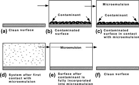
FIGURE 2.7 Progression from a clean surface to a surface with adhered contaminant to the same surface upon contact with a microemulsion.
The contaminant material is spontaneously drawn into and incorporated with the microemulsion phase with no addition of shear or mechanical energy. This makes “spontaneous” microemulsion cleaning a very useful method for cleaning of surfaces in which it would be difficult or impossible to provide mechanical energy, e.g. in cleaning of porous media in petroleum reservoirs and wellbores.
4 Surface Cleaning and Contaminant Removal with Microemulsions
Cleaning of surfaces with microemulsions is a complex process that depends on several factors, including the concentration and composition of the wash solution, temperature, mechanical energy, and the nature of the substrate to be cleaned [59].
The substrates could be either (1) hydrophobic surfaces (oil-wet) such as polypropylene, polyethylene and polystyrene that have contact angle to water in the range of 90–100° or (2) hydrophilic (water-wet) surfaces such as glass surfaces that have contact angles to water in the range of 20–30°. Surfaces such as heterogeneous rock formations present mixed wettability. The surface contaminants could be liquids or solid particles and can have different degrees of adhesion to the surface, depending on their composition and properties.
Key aspects that determine the reduction of the adhesion between the soil and the substrate are the particle and/or liquid–substrate interactions, cleaner–contaminant interactions, and cleaner–substrate interactions. Mechanical energy and flow dynamics are additional aspects that play an important role in the cleaning process.
The primary mechanism involved in the cleaning process with microemulsions is solubilization of oily materials into the core of the micelles to form swollen micelles. Another mechanism that is also observed is soil roll-up and microemulsification of the oily material [52]. The IFT between the oily material and the washing or cleaning fluid plays an important role in the cleaning process. Microemulsion systems that exhibit ultralow IFT in the Winsor III phase region, passing through a minimum at the washing condition of the surfactant–soil–water system, may be excellent cleaners.
5 Design of Microemulsion Cleaners and Evaluation Techniques
The design criteria of microemulsion fluids depend on the specific application. Some of the requirements that determine the design of a microemulsion include the cleaning time, solubilization or removal of the oil from the surface, and resulting wettability of the surface. Depending on these requirements, the design could be an optimum formulation or a Winsor III, Winsor IV or a Winsor I on the borderline of Winsor III. This last system could be designed to form an in-situ microemulsion during the cleaning procedure.
Formulation of microemulsions with these desired characteristics requires proper choice of a surfactant blend plus other additives, such as cosurfactant(s) and linkers to form the appropriate fluid mixture that is most efficient for a broad range of conditions (types of oily material to be cleaned, salinities, O/W ratio, temperatures, etc.). The formulation studies that can be used to select the best microemulsion for cleaning applications include a solvent or an oil with EACN similar to the material to be cleaned, together with freshwater or brines (NaCl, CaCl2, NaBr, and CaBr2), and surfactant blends over a temperature range that covers the application conditions. Short-chain alcohols and linkers are optional additives in the formulation.
The physicochemical characterization of the microemulsion systems includes studies of phase stability, phase behavior, and molecular interaction [60]. The mechanism of micellar solubilization and microemulsion characterization can be studied by methods such as nuclear magnetic resonance (NMR), ultracentrifugation, X-ray diffraction, small-angle neutron scattering, and differential scanning calorimetry [60–63]. NMR is a very useful technique in the studies of phase behavior and microstructure. Formulation scan is a practical way to study the phase behavior of the surfactant–water–oil microemulsion systems. In addition to the formulation scans, the IFT, wettability and laboratory procedures adapted for the specific applications are used to evaluate the effectiveness of these microemulsion systems.
IFT between liquids can be measured by a number of methods [64]. Dynamic IFT measurements have been recognized to be important for understanding interfacial processes in industrial operations that involve multiphase systems [65], such as microemulsion cleaning processes. In industrial operations that involve liquid–fluid interfaces, the composition of the fluid at the interface is constantly refreshed and does not reach equilibrium.
Techniques for measurement of the dynamic IFT include the maximum bubble pressure, growing drop (bubble), oscillating jet, and pulsating bubble methods. If the IFT of the measured system reaches ultralow values such as those encountered in microemulsions used for drilling fluid removal (lower than 10−2 mN/m) from rock and metal surfaces, the most appropriate techniques are spinning drop tensiometry and surface light scattering [64–66].
The maximum bubble pressure technique is useful for measuring IFT between fluids that have similar density. Under these conditions commonly used techniques for measuring IFT fail, because they depend on the existence of a significant density difference. An example where this technique has been used is the measurement of IFT between bitumen and water which have an extremely small (<0.001 g/cm3) density difference [67].
6 Microemulsion Cleaning Applications
The distinctive properties of microemulsions (high solubilization of oil, low IFTs, and spontaneous formation) make these fluids very attractive for a variety of cleaning applications. Microemulsions have been used in industrial cleaning processes and household cleaning applications. Some of the applications include domestic and industrial laundry, cleanup of wastewater, cleaning of contaminated soil and various applications in the oil and gas industry.
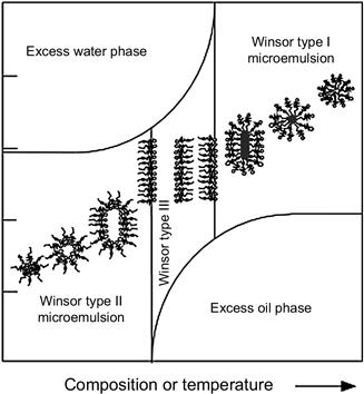
In each of the following examples of microemulsion cleaning applications, the hydrocarbon or oily materials are solubilized in the aggregated cores of the micelles, producing swollen micelles and, as a consequence, its surface curvature tends to decrease, producing changes in the phase behavior, as shown in Fig. 2.8. Depending on the application conditions, phase changes can be triggered by temperature or by composition changes. In some applications, the treatment solution is designed to be a microemulsion system with the phase behavior bordering between Winsor I and Winsor III, such that when the solution contacts the oily contaminant, the oil is solubilized into the micelles by a diffusion mechanism and the system transitions to the Winsor III-type microemulsion. In other applications, the treatment solution may be designed as an oil-based Winsor II-type microemulsion system on the borderline of the Winsor III system. When the solutions are in the Winsor III condition (or optimum formulation), the IFT drops very dramatically to near zero, which facilitates incorporation of oil or water into the amphiphilic structures.
The use of microemulsion fluids is an emerging technology for cleaning synthetic and hydrocarbon material in the oil and gas industry. Applications range from surface to downhole applications and from static conditions to dynamic displacement in the turbulent flow. Some of the microemulsion cleaning applications include the following:
• Removing oily material from oil-contaminated drilling cuttings brought to the surface during the drilling operation of the well.
• Cleaning metal surfaces of the pipes and rock surfaces of the wellbore during the displacement of brine-in-oil emulsion drilling fluids (typically called oil-based mud (OBM) or synthetic-based mud) to water-based fluids during the wellbore construction of the well.
• Cleaning wellbores and removing the filter cake formed by the brine-in-oil emulsion drilling fluids at the surface wall of the wellbore after the drilling process to assure the well produces the expected crude oil production.
• Removing hydrocarbon deposits, sludge or viscous crude oil emulsion, and formation damage due to drilling fluid invasion in the near-wellbore region of the production zone of oil and gas wells.
The following discussion focuses on the detailed mechanisms and examples of the aforementioned applications.
6.1 Cleaning of Oil-Contaminated Drill Cuttings
Drilling fluids are specialized fluids that are circulated down the well during the rotary drilling operation to perform various functions, such as cooling and lubricating the drilling bit and flushing the rock cuttings (drill cuttings) to the surface. Offshore and onshore disposal of drill cuttings generated from wellbores while drilling with oil-based or synthetic-based muds is still an expensive and challenging process. In some areas, such as the North Sea, legislation established a maximum allowable discharge of <1% oil. This regulatory action is a consequence of the environmental impact of oil-wet drill cutting accumulations on the ocean floor ecosystem, even with synthetic-based drilling fluids that pass all required environmental tests.
Drill cuttings are typically agglomerates of rock fragments, crude oil and drilling mud. In general, oil is either coated onto the drill cutting surfaces (surface oil) or trapped/occluded inside the porous drill cuttings clusters due to high capillary forces, as shown in Fig. 2.9. To decontaminate these drill cuttings, surface oil and trapped oil must be thoroughly removed.

Various mechanical and chemical processes, including microemulsions, could be applied to convert these oil-contaminated drill cuttings to an acceptable clean form. Microemulsions could treat oil-contaminated drilling cuttings simply by mixing the solids to be treated with an aqueous wash solution that is a highly diluted microemulsion. This type of wash could offer high cleaning efficiency while requiring minimum energy and mechanical input. The oil is liberated from the drill cuttings into the wash solution by the reduction of the oil/wash solution IFT.
Microemulsion formulations that include surfactants, freshwater or seawater, base-oils used in drilling fluids, and water softener are studied with the object of formulating wash solutions for treating oil-contaminated drill cuttings. For this particular application, surfactant blends formulated with anionic–nonionic surfactant mixtures and with commonly known water softeners, such as sodium silicate, were used.
Table 2.1 presents the IFT measured between various oils and a wash solution selected from studies that included a number of surfactant mixtures formulated with seawater. The tests were performed with common base-oils used in drilling fluids. According to Table 2.1, the surfactant mixture used produced low IFT in a range of 10−3 and 10−4 mN/m with surfactant concentration between 0.5 and 2 wt% in the wash solution. Studies of the phase behavior performed with this oil–water–surfactant system formed a Winsor III microemulsion.
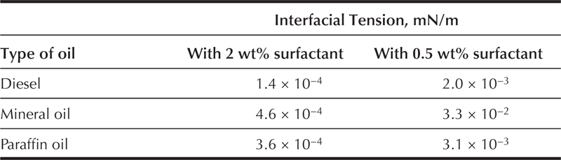
The wash solution used in the tests shown in Table 2.1 was used to treat various oil-contaminated cuttings with oil content ranging between 10 and 13 wt%. The results of the wash process showed a reduction of oil retention on the cuttings (ROC) to the order of 3 wt%. The same formulation with the addition of a cosolvent reduces the ROC to around 1 wt% (Fig. 2.10).

6.2 Wellbore Cleanup During Displacement of Oil-Based Drilling Fluids to Water-Based Fluid
When displacing and completing oil and gas wells, contaminants, such as oil-based drilling fluids, drilled solids, and other debris found in casing and risers, should be removed quickly and efficiently. Fluids incompatibility is a major issue when oil and gas operators have directly displaced the oil-based drilling fluid from a wellbore with an aqueous fluid such as brine and/or cement after running a casing string.
The vast chemical dissimilarity between the oil- and water-based fluid systems could produce a highly viscous fluid–fluid mixture when oil-based drilling fluids and water-based fluids come into contact with each other. This can result in spikes in viscosity, fluids channeling, poor cleaning, settling of solids, insufficient water-wetting, etc., decreasing the displacement efficiency. These inefficient displacements could lead to poor cement bonding, squeeze jobs, communication between zones and, in some cases, blowouts [68–71].
Microemulsion technology has been used as a spacer fluid between the oil-based drilling fluids and brine completion or between the oil-based drilling fluids and cement slurry to resolve this problem. This type of spacer prevents the aforementioned problem and cleans the oily debris from the casing and water-wets the metal surfaces and rock formation to promote good cement bonding [72,73].
Selecting the proper composition of the microemulsion spacer that meets the requirements of oil-based drilling fluid displacement efficiency and changes the wettability of the surface casing from oil-wet to water-wet is typically dependent on the drilling fluid type, composition, and wellbore conditions [73,74]. Efficient displacement is defined as the complete removal of the oil-based drilling fluid from the wellbore and from the metal surfaces, as illustrated in Fig. 2.11. Figure 2.11 shows a metal sleeve surface exposed to the oil-based drilling fluid for 15 min at 100 rpm and at 65 °C, and the same sleeve after exposure for a few minutes to an efficient microemulsion spacer. The metal sleeve coated with drilling fluid formulated with synthetic oil is shown below in Fig. 2.11(a). Visual inspection of the sleeve in Fig. 2.11(b) provides an indication of the cleaning effectiveness of microemulsion spacers. The results indicate >99.5% of the drilling fluids were removed and the metal surface is rendered water-wet.

FIGURE 2.11 The stainless steel sleeve after (a) exposure to synthetic-based mud (SBM) and (b) treatment with the microemulsion spacer.
Similar cleaning efficiency was obtained when this microemulsion formulation was used to displace oil-based fluid and to clean the casing, riser and drill pipe during the wellbore construction of oil wells. Figure 2.12 shows a drill pipe covered in drilling fluids before displacement in an oil well. This closely resembles the situation of the metal surface prepared in Fig. 2.11(a). Figure 2.12 also shows the drill pipe after a single displacement using the microemulsion formulation. Observation reveals results very similar to those obtained in the laboratory.
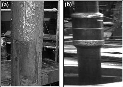
FIGURE 2.12 Photographs of a drill pipe (a) before and (b) after displacement with the microemulsion spacers.
To avoid channeling problems and to remove a majority of the debris from the rock and metal surfaces during the fluids displacement, the spacer that contacts the oil-based fluids must have rheological properties, such as viscosity, relatively higher than those found in the drilling fluids. This is achieved by adding a viscosifier substance to the spacer microemulsion fluid. To assure total removal of the oil and to completely water-wet the surfaces, the viscosified spacer is followed by a second microemulsion spacer formulated in brine that completes the cleaning and renders the surfaces water-wet.
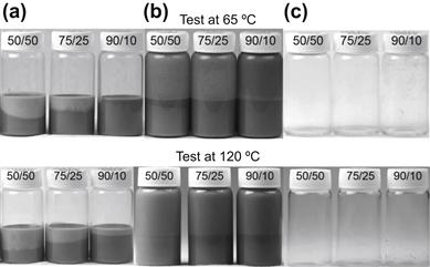
A number of tests are used to evaluate the cleaning efficiency of the microemulsion systems, including rheology of spacer/drilling fluid blends, sleeve cleaning tests and vial cleaning tests. Figure 2.13 shows an example of vial tests where a viscosified microemulsion spacer is used to remove oil-based drilling fluid from glass surfaces. A series of vial tests that simulate the drilling fluid/spacer interface are carefully prepared with oil-based drilling fluid and the spacer fluid at ratios between 50/50 and 90/10. Figure 2.13 shows the appearance of the vials after completing the test procedure that involves mixing, aging for 16 hours at selected temperature, pouring out and a slight rinsing with water. The appearance of the vials reveals the cleaning and water-wetting effectiveness of the microemulsion spacer fluid for cleaning of surfaces wetted with oil-based drilling fluid. The results of the tests at 65 and 120 °C were very similar, because the formulation studies defined a surfactant blend–water–oil system that maintains useful properties in a broad range of temperature.
6.3 Near-Wellbore Cleaning in Oil and Gas Wells
Microemulsion fluids have been successfully used to effectively resolve the persistent problem of near-wellbore formation damage. The term “formation damage” in the oil and gas industry refers to any process that causes a reduction in the natural productivity of hydrocarbons in the porous media in an oil and/or gas well. This is a by-product of the drilling, completion, and production process and can be attributed to many factors. In open-hole (OH) and cased-hole (CH) wells, hydrocarbon flow may be impeded by various formation damage mechanisms caused during the drilling and completion process and/or the production phase of the well. Formation damage may originate from fluid invasion into the surrounding rock during the drilling operations, organic deposition from the reservoir hydrocarbon system, oily debris left downhole, adsorption of additives such as surfactants and polymers used as operation fluids, and/or fluids incompatibility. The damage caused from incompatibility between in-situ reservoir fluids and any of the operation fluids typically results in in-situ water-in-crude oil emulsions or sludge formation. These fluids include drilling fluids, completion fluids and stimulation fluids.
The high oil solubilization, high diffusion through porous media, and the reduction of IFT between organic and aqueous phases to near zero make microemulsions excellent candidates for removing formation damage. These systems are excellent choices for cleanup and removal of synthetic or oil-based drilling fluids filter cake in OH completion applications. Formulations have also been developed for CH perforation applications, as well as for postdrilling remediation treatments to remove formation damage around the perforation or fracture zones.
The selection of the microemulsion fluid technology for near-wellbore cleaning depends on the specific application. For example, in a CH completion well, for either prevention or remediation of formation damage, a Winsor IV-type microemulsion performs best. In OH wells, where a uniform filter cake cleanup is required, the best solution is to pump downhole a Winsor I system approaching the transition to optimum formulation that will form an in-situ microemulsion when it contacts the filter cake. This is considered to be the best method to achieve effective OBM filter cake removal throughout the hole section.
6.3.1 Removal of Oil-Based Fluid Filter Cake in OH Completion Wells
Oil-based drilling fluids are emulsions formulated with various additives that include emulsifiers, viscosifiers, lubricants, and solids (e.g. calcium carbonate and barium sulfate) to adjust the fluid density. During circulation of the drilling fluids under pressure from surface to downhole, leak-off or a small volume of filtrate of drilling fluids is expected to pass through the porous medium, leaving a filter cake around the wellbore wall of the porous medium. The filter cake includes a combination of the drilled solids, the solids that have been added to the drilling fluid, chemical additives, brine and/or oil. The formation of a filter cake (typically a few millimeters in thickness) is extremely important for controlling fluid losses to the rock formation during the drilling process; however, the filter cake must be removed after the drilling process is finished. Failure to remove the filter cake impedes the expected hydrocarbon production. An additional near-wellbore damage (reduction of hydrocarbon production) could result when poor filter cake formation allows filtrate invasion deep into the rock formation.
The cleaning time required to affect good wellbore cleanup depends on the filter cake properties, such as cake thickness, toughness, slickness and permeability, as well as the downhole temperature. In the case of oil-based filter cake, the cleaning fluid is pumped and allowed to soak for a minimum of 24 or 48 hours, and sometimes longer, because it is difficult to predict the exact properties of the filter cake.
One-step oil-based filter cake cleanup technology uses a single-phase microemulsion and conventional acids, in a single blend, to solubilize the oil into the microemulsion, reverse the wettability of the filter-cake solids, and simultaneously decompose its acid-soluble components [75,76]. Reversing the wettability of the filter cake, using surface-active chemistry, facilitates acidizing by preventing a sludge that could form between the acid and the emulsified cake and by making acid-soluble particles unavailable to unspent acid. Besides the advantage of reduced skin damage in the well, increased hydrocarbon recovery and/or increased water injection rates, a “one-step” near-wellbore cleanup method could save an operator oil company valuable rig time.
To select an efficient formulation for filter-cake cleanup, phase behavior studies that include a solvent or base oil used in oil-based drilling fluids, together with brines (NaCl, CaCl2, NaBr, and CaBr2), and surfactant blends were evaluated over a temperature range of 25–90 °C. Short-chain alcohols and acids are optional additives in the formulation and were evaluated in the phase diagrams. Phase behavior was studied using an oil/aqueous phase ratio of 1–4. The oil phase used in the studies includes solvents and base-oils used for oil-based drilling fluids. The data obtained from the phase behavior studies were used to build phase diagrams, allowing better understanding of capabilities and possible performance of the fluid formulated with a particular surfactant–oil–brine system.
Figure 2.14(a) shows an example of phase behavior of a system used for filter-cake cleanup. In this particular case, the oil–water–surfactant phase behavior study used the same type oil found in the oil-based drilling fluids, to assure good oil solubilization when the cleanup fluid contacts the filter cake. The example shows a system that is very sensitive to changes in salinity, such as the systems formulated with only anionic surfactants. The phase behavior shows that the increase in salt concentration in the fluid formulations causes the fluids to approach close to the boundary of WI–WIII. Based on this observation, two formulations from the same system would perform very differently, insofar as cleaning the same material, if they are formulated at very different salinities. Figure 2.14 shows photographs of the discs with an oil-based filter cake before (Fig. 2.14(b)) and after the cleaning tests with Formulation 1 (Fig. 2.14(c)) and Formulation 2 (Fig. 2.14(d)). Formulation 2, formulated in 15% CaCl2, has much better cleaning efficiency than the Formulation 1 with 3% CaCl2, which is located much farther away from the transition from Winsor I to Winsor III-type microemulsion than is Formulation 2. The clean state of the disc indicates that the oil of the filter cake was solubilized, turning the solids water-wet. Once the calcium carbonate solids used in the fluids became water-wet, they were dissolved by the acid (around 10% by weight in the fluid).
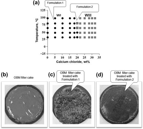
FIGURE 2.14 Cleaning performance of two fluids selected from the surfactant–oil–brine system presented in Fig. 2.14(a).
Regain permeability tests are performed to evaluate the ability of the microemulsion treatment fluid to remove oil-based filter cake and to remove damage caused by wettability changes and in-situ water-in-crude oil emulsion formation. Figure 2.15(a) shows a schematic of a permeability test setup in a permeameter equipment. The tests are run using ceramic discs as porous media. The test procedure begins with measurement of the initial permeability (Ki) to the brine. The following step is the formation of a filter cake on a ceramic disc, followed by treatment with the microemulsion soak solution for a specified period of time at a specific temperature. After the soak period, the final permeability (Kf) was measured at various flow rates. Then, the cell is opened and the residual filter-cake solids are assessed for water-wetness and dispersion ability.
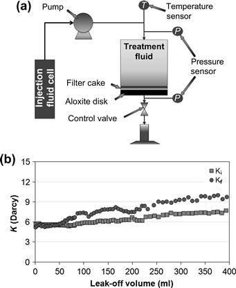
FIGURE 2.15 Regain permeability test (a) schematic of permeability tests setup, and (b) regain permeability results.
Figure 2.15(b) shows the permeability data recorded during the tests using the formulation selected from a point in the phase diagram (Fig. 2.14(a)) that corresponds to a borderline transition from Winsor I to Winsor III. The results show that the final permeability, measured after the soaking, was even higher than the initial permeability, which is a desirable result. The formulation removed the oil and acid-soluble solids of the nonaqueous fluid filter cake, turned the residual solids from oil-wet to water-wet condition, and cleaned the porous media (ceramic disc). These results are an indication of hydrocarbon production enhancement that could be obtained by using microemulsion cleaning fluids in oil and gas wells.
6.3.2 Removal of Formation Damage in CH Completion Wells
Other downhole cleaning application of microemulsion fluids is in CH wells where the crude oil production may be impeded by formation damage. Some of the causes of formation damage or reduction of crude oil production encountered in wells completed with CH include wettability changes, in-situ emulsion formation or sludge, and water blockage [77,78].
An approach to treat these wells is to use a microemulsion fluid that removes formation damage in the near-wellbore region [78]. The treatment fluids diffuse into the perforated rock matrix and spontaneously solubilize oil and remove the blocking material in the pore rock. The fluid simultaneously water-wets and fluidizes solids in the damaged porous media to prepare them for easy removal during production operations. For this particular application the Winsor IV-type systems are used to have a fast cleaning action. In addition to the ultralow IFT, low contact angle, and good cleaning requirements, the system used for this particular application needs to provide a fast separation when evaluated in emulsion tests with crude oil. This type of test is performed by evaluating the treatment fluid in emulsion risk tests.
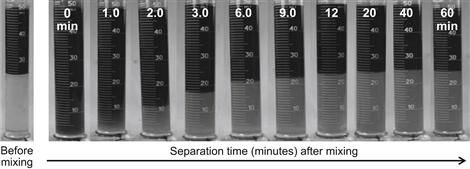
The risk of water-in-oil emulsion formation in porous media is evaluated using classical bottle tests. These tests are performed using a 50/50 blend of crude oil/microemulsion fluid at the required temperature for applications. The mixtures are vigorously mixed by hand-shaking in a graduated cylinder. The cylinder is then allowed to rest at a predetermined temperature while separation of the fluids is observed.
Figure 2.16 shows the results of an emulsion test using crude oil and the microemulsion fluid treatment. A total separation of the fluids was achieved in about 20 min. This result indicates that this particular microemulsion evaluated is effective in preventing and removing formation damage caused by blockage sludge formation in the porous media.
6.4 Other Cleaning Applications
Other cleaning applications of microemulsion fluids that have been reported include cleaning of wastewater, fabrics and textiles, soil contaminated with jet fuel, frescoes and paintings that have been polluted, fracture paths in shale gas formation, and sweeping of oil in petroleum reservoirs.
In this section, the term “oily” is used to mean not only nonaqueous liquids, with hydrocarbon character, such as mineral oils, manufactured solvents, crude oil or petroleum, refined petroleum, and vegetable oils, but also semisolid materials such as tar, asphalt, grease deposits, etc.
6.4.1 Wastewater Cleaning and Microemulsion Froth Flotation
Microemulsion technology has been shown to be effective for cleanup of oily wastewater [79,80] in batch and continuous processes. Experimental results indicate maximum oil removal from water to occur at surfactant concentrations at or near the critical composition at which microemulsions form in the system. The most favorable condition corresponds to Winsor III microemulsion. Water purification by microemulsion froth flotation has been studied for removal of contaminants such as motor oil, diesel, chlorohydrocarbons, carbon black, fine mineral particles, etc. The process typically involves identification of an appropriate surfactant or surfactant blend for the “oil”/water/surfactant system, followed by the studies of microemulsion formation in response to salinity of the aqueous phase, and determination of the optimum air bubbling mechanism to cause the contaminant “oil” to float to the air–liquid interface at which a surface skimming process removes the froth and contaminant. This froth flotation separation process involves various phenomena, and variables, such as attachment of the oily droplets or swollen micelles of microemulsion to air bubbles, the size distribution of the oily droplets and air bubbles, dynamic IFTs, froth stability, and ability of the froth to suspend the floated oily droplets [79]. Experimental results favor use of small quantities of surfactant in the system near the critical composition for microemulsion formation. This method can be useful for purification of wastewater and recovery of valuable trace contaminants.
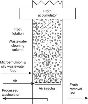
An interesting application is the use of microemulsions in the froth flotation process to cleanup wastewater [79,80]. In this process the surfactant interacts with the air bubbles and with the dispersed oily droplets or dissolved oily material in the wastewater. Thus, swollen surfactant micelles form in the contaminated aqueous phase. Figure 2.17 shows that the air is introduced into the system via a bubbler device. The surfactant concentrates at the air/water interface with hydrophobic part(s) oriented toward the inside of the air bubble and the hydrophilic part orients in the aqueous phase. With the oily droplets, the hydrophobic part of the surfactant orients toward the center of the oily drop and the hydrophilic part orients toward the aqueous phase. The dispersed oily droplets are attracted to the rising air bubbles and accumulate in a foam or froth layer at the water surface. Skimming of the surface removes the froth.
This method can also be applied to cleanup of solid particles such as sand or soils, by contacting the contaminated sand or soil with an aqueous solution containing surfactant that will form a Winsor III microemulsion. The wash liquid would then be separated from the solids and subjected to a froth flotation step in which the contaminant would be removed by air injection into the aqueous surfactant system containing the contaminant “oil”.
6.4.2 Microemulsion Cleaning of Contaminated Soil and Groundwater
The contamination of soils and groundwater with volatile and/or nonvolatile organics from underground storage tanks, spills, and improper waste disposal presents a major remediation problem [81]. Various publications have discussed the application of microemulsions and mechanisms of contaminant removal at various conditions (temperature, salinity, and surfactant concentration). One particular example is the removal of chlorinated hydrocarbons used in cleaners and degreasers products that are commonly found in the groundwater [82].
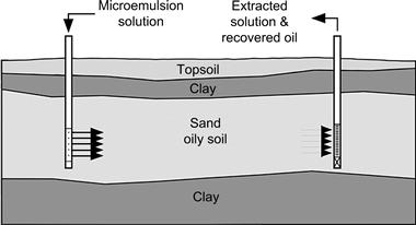
Another variant of the oily soil cleaning process may involve the injection of a microemulsion solution at an injection well into a bed of contaminated soil and withdrawal of the injected solution plus oily contaminant via a removal well, such that the solution migrates from the injection site to the removal site, flushing and cleaning the contaminants from the channels in the porous media. Figure 2.18 shows a schematic of the underground contaminated soil treatment and displacement out of the ground.
An example is the use of microemulsion technology to clean soil contaminated with tetrachloroethylene. A field demonstration showed that this type of fluid is able to considerably reduce the percentage of tetrachloroethylene in soil. After 10 pore volumes of flushing, the overall contaminant in the underground soil was considerably reduced when compared with results from using conventional technologies [83].
Recovered contaminant and aqueous solution of surfactant could be fed to a process unit in which air injection can be used to create a froth to concentrate the microemulsion and the oily contaminant at the top surface of the liquid. Examples in which this type of process has been used include the decontamination of soils near fuel-spill sites or contaminated soils from fuel storage tank leakage.
6.4.3 Microemulsion Cleaning of Textiles
An important application in which microemulsions are useful involves cleaning of oily contaminants from fabrics and textiles. The contaminants may be either particulate soils or liquids. Both types of contaminants adhere to the substrate textile as a consequence of van der Waals and related interactions between the contaminants and substrate [84].
Studies have shown that, for certain cases, traditional cleaning of fabrics and textiles using volatile organic solvents or surfactant solutions can be replaced with specially-formulated environmentally friendly microemulsions in aqueous solutions. Microemulsion cleaning of fabrics and textiles is linked with the general notion of detergency.
The primary cleaning mechanism of microemulsion is the solubilization–emulsification mechanism at the soil–detergent solution interface [52]. This mechanism is directly influenced by the phase behavior of the corresponding oil–water–surfactant system used. The microemulsification is influenced by the variables encountered in the process, such as the composition and surface properties of the fabric, amount and type of soil or contaminants, water hardness and temperature [52,85].
Cleaning of fabrics involves use of appropriate surfactants to create microemulsions at the optimum formulation conditions or near the transition to a Winsor III-type microemulsion, during the washing or cleaning process. This very low IFT condition facilitates solubilization and incorporates the oily contaminant and subsequent removal of the contaminant from the fabric by flushing the fabric with an aqueous solution. In application, the microemulsion cleaning solution is reusable multiple times, because the performance and phase behavior of the cleaning solution change very little in each use, due to the relatively large amount of presolubilized oil and the small amount of oily contaminant removed in each cleaning.
In some cases, stains on fabrics and textiles can be removed by application of an appropriate pretreatment using a concentrated surfactant system that forms a microemulsion with the oily contaminant on the fabric. The concentrated surfactant needs to remain in contact with the oily contaminant for a sufficient time to diffuse into and mix with the oily contaminant, prior to flushing of the stained area with a clean aqueous solution.
6.4.4 Microemulsion Cleaning Using Nonaqueous Solvents
Another interesting application of microemulsions for cleaning is their use in systems that do not contain water. Some applications [86,87] use substances like carbon dioxide (CO2) as the continuous phase, instead of water, to effect a dry-cleaning process for situations where materials being cleaned would be damaged by contact with water. Special surfactants are used for these systems and cleaning applications. Surfactants for CO2 microemulsions have been formulated from special copolymers composed of polystyrene segments (CO2-phobic) and modified fluorine-substituted acrylonitrile segments (CO2-philic). Other surfactants that have been studied for CO2 textile cleaning applications include di-n-octylamine [88,89]. One application is in the dry-cleaning of special fabrics. Other applications are the cleaning of electronic components and assemblies that would be damaged by contact with water.
6.4.5 Microemulsion Cleaning of Building Exteriors
Microemulsions can be used for cleaning of the exterior surfaces of buildings. Tourists and travelers may recall the sooty historical buildings, cathedrals and castles in parts of northern cities in America, Europe and the Old World caused partly by decades or centuries of exposure to smoke and soot from chimneys and heaters that used coal or other fuels that emitted particulates that resulted in the dingy gray look of originally beautiful stone and masonry cathedrals, palaces and houses of government. Prior to the development of microemulsion technology, such buildings and monuments were subjected to cleaning procedures that used harsh sandblasting and/or pressure washing, causing more harm than good by permanently removing layers of the building surfaces. With microemulsion technology, such surfaces can be cleaned by using effective, fast-acting microemulsion solutions that penetrate the pores, cracks and crannies of the stone edifices to spontaneously form microemulsion nanostructures that solubilize and incorporate the contaminants, and facilitate their subsequent removal by gentle washing of the surfaces with clean water [90].
6.4.6 Microemulsion Cleaning of Frescoes and Artwork
Another application involves use of microemulsions to clean frescoes and paintings that have become coated with pollutants or damaged by vandals with graffiti. Special microemulsion systems have been able to remove the contaminants with minimal damage to the original artwork [91].
Studies in microemulsion cleaning proved that highly insoluble acrylic polymers and organic materials employed in works of art and architecture can be solubilized in microemulsions. An example of this application is the complete cleaning of an acrylic-contaminated painting successfully achieved by using a microemulsion system. The microemulsion system reduced about 95% of the total amount of the organic phase (1% w/w) on the contaminated piece of art. The microemulsion was particularly effective for the cleaning of a secco painting, a fragile painting difficult to clean using conventional methods, as in the case of the restoration of the wall painting by Vecchietta in the Sacristy of Santa Maria della Scala, in Siena, Italy [91].
6.4.7 Microemulsion Cleaning of Crude Oil Reservoirs
A very interesting challenge for microemulsion cleaning is the field of enhanced recovery of hydrocarbons from depleted reservoirs. This application is essentially an extension of the types of cleaning principles and applications described in the foregoing sections. Surfactant technology has been used in some chemically-enhanced oil recovery (EOR) applications with the objective of mobilizing the residual oil through microemulsion systems that generate ultralow crude oil/water IFT to overcome capillary forces and to enable oil and water to flow [92–94].
To design microemulsion systems for chemical EOR applications that cover a broad range of reservoir temperatures and salinities encountered in formation water (from low to about 30,000 mg/l), formulation studies need to include parameters such as type and temperature, salinity and composition of the crude oil, and concentration of the surfactant. In addition to the phase behavior, IFT and wettability, core flow studies are used to evaluate the microemulsion system in a porous media [94].
Research in chemical EOR started in the 1970s. In the period 2001–2013, the number of publications in this area had significantly increased, as evidence of the large amount of ongoing research at universities and research centers of the oil industry and by surfactant manufacturing companies. However, the recognition of the special properties of microemulsions suggests that development of processes for formation of in-situ microemulsions in depleted petroleum reservoirs is an exciting field for more research and development. In depleted reservoir systems, the natural flow of hydrocarbons from the porous media has effectively ceased, as a result of pressure depletion, as fluid was removed by production of the oil, gas and water. Under such conditions, some hydrocarbon reservoirs may have been subjected to flushing of additional hydrocarbons from the porous media using water-flooding technology. Even if water-flooding and other techniques have been used, there remains some amount of hydrocarbons in the reservoir that are effectively immobile and trapped in dead ends, or tortuous pathways which were bypassed by the path of least resistance physics of the flushing processes.
All of the initial work was directed toward chemical EOR in sandstone reservoirs, because the high-divalent environment encountered in carbonate reservoirs would create salt precipitation problems with the sulfonate surfactants typically used in these applications. Later, the application was extended to carbonate reservoirs with the incorporation of other types of surfactants [93].
At this stage, chemical EOR has advanced to overcome some of the problems encountered in the past. Research at universities and in the petroleum industry has resulted in (1) a reduction of required surfactant concentration, which is economically very important, because continuous injection in reservoirs results in the use of very large volumes of surfactant and other additives; (2) development of a large number of surfactant molecular types to obtain the required phase behavior of the microemulsion system with different crude oils; and (3) better understanding of interactions between the rock formation and alkali/surfactant systems used in chemical EOR injection that has resulted in reduction of surfactant adsorption, lowering the required surfactant concentration.
6.4.8 Microemulsion Cleaning of Fracturing Gels from Shale and Other Rock Formations
A very contemporary application for microemulsion cleaning pertains to development of oil-shale and gas-shale energy resources [95,96]. Shales have the characteristic property of fissility, which enables them to be fractured along planes. When very low porosity shales contain significant amounts of oil and/or gas, one typical method used to produce the hydrocarbons is to fracture the shales using high-pressure injection of fluids that can produce fracture pathways in the shale deposits. Special materials are then injected that prop open the cracks and fissures created by the rock fracturing operation. A gel-type fluid is used to facilitate introduction of proppant materials into the extended fractures. Following the fracturing operation, it is desirable to remove the gel substance to permit easier flow of the hydrocarbons through the fractures into the well. The situation is complicated by the location of the reservoirs far below the surface of the Earth, and by the fact that it is not practical to use mechanical energy to remove the gel material from the fractures. This is a great opportunity for microemulsion technology, because microemulsion solutions can be formulated to incorporate the gel material into the microemulsion structures instantaneously, without need for mechanical energy. To further minimize problems that might arise, if clay minerals are included in the rock, the microemulsion solutions could be formulated using nonaqueous substances, such as CO2. When the oil or gas wells are placed in production, the pressure of the hydrocarbon fluids can displace the microemulsion solution from the fractures, enabling production enhancement by lowering hydraulic resistance in the fracture pathways and network. The use of microemulsion technology for this challenging application could be very successful.
7 Current Trends and Future Developments
Microemulsions, incorporating oil and water, have been increasingly used to formulate fluid systems for cleaning applications. Such fluids have the advantage of cleaning with minimal or no requirement for mechanical energy.
Important properties of microemulsions include their ability to form spontaneously, their ability to absorb/solubilize substantial amounts of water and/or oil, their ultralow IFT, and their ability to alter wettability of oil-wetted surfaces. Not surprisingly, microemulsions have found applications in all industries that use cleaning processes. Some current applications include household cleaning (hard and soft surfaces) applications, such as laundry, countertops and floors. Industrial applications include large-scale laundry operations, cleanup of oily wastewater, cleaning organic contaminants on artwork surfaces, such as fresco paintings. Microemulsions have also been used in a number of environmental remediation applications, including solubilization and removal of chlorohydrocarbons from contaminated soil.
The oil and gas industry uses microemulsions in various applications that range from surface cleaning operations (oil removal from drill cuttings and equipment) to downhole well cleaning, and to increase crude oil recovery from rock formations in oil wells. An application where universities and industry have been doing a considerable amount of research is in microemulsion formulations for cleaning reservoir formations to increase oil and gas production.
Another application that started in recent years is the use of microemulsions to increase water flow back in shale gas wells. This application has a good potential for growth, but there are many variables related to fluid/rock interactions and fluid/fluid interactions in the process that need to be defined by experiment and understood.
Microemulsions are quite complex systems that are dependent upon many variables. There remains a wide gap between current scientific knowledge and the practical information available to those who develop fluid formulations for industrial applications.
Future developments of microemulsions for cleaning of surfaces are a wide-open and fertile area for research. Advances will depend upon the advent of a host of new surfactant molecules that can be used to formulate surfactant packages that generate/design microemulsions having capabilities for specific applications, in petroleum recovery, pharmaceuticals, medical practice, chemical reactions, catalysis, decontamination/cleaning of soils and surfaces, cleaning and recovering nanoparticles for reuse, etc. Likewise, future developments may include microemulsion systems that involve pressure-responsive supercritical components [97], such as application in ultradeep wells in crude oil and gas reservoir. Other possible areas of applications may include microemulsions for hydrate control and removal in cold environments subsea and the arctic.
References
1. Hoar TP, Schulman JH. Transparent water-in-oil dispersions: the oleopathic hydromicelle. Nature. 1943;152:102.
2. Schulman JH, Riley DP. X-ray investigation of the structure of transparent oil–water disperse system. J Colloid Sci. 1948;3:383.
3. Salager J-L, Anton RE, Sabatini DA, Harwell JH, Acosta EJ, Tolosa LI. Enhancing solubilization of microemulsions – state of the art and current trends. J Surfactants Deterg. 2005;8:3.
4. Ezrahi S, Aserin A, Garti N. Aggregation behaviour in one-phase (Winsor IV) microemulsion systems. In: Kumar P, Mittal KL, eds. Micelles, Membranes, Microemulsions and Monolayers. New York, NY: Marcel Dekker; 1999;185–244.
5. Salager JL, Anton R. Ionic microemulsions. In: Kumar P, Mittal KL, eds. Micelles, Membranes, Microemulsions and Monolayers. New York, NY: Marcel Dekker; 1999;247–280.
6. Xie M, Zhu X, Miller GW, et al. Generic patterns in the microstructure of midrange microemulsions. In: Friberg SE, Lindman B, eds. Micelles, Membranes, Microemulsions and Monolayers. New York, NY: Marcel Dekker; 1992;145–158. Organized Solutions, Surfactant Science Series vol. 44.
7. Zana R, Lang J. Dynamics of microemulsions. In: Friberg SE, Bothorel P, eds. Micelles, Membranes, Microemulsions and Monolayers. Boca Raton, FL: CRC Press; 1987;153–172.
8. Danielsson I, Lindman B. The definition of microemulsion. Colloids Surf. 1981;3:391.
9. Winsor PA. Solvent Properties of Amphiphilic Compounds. London, UK: Butterworth; 1954.
10. Bellocq M. Ionic effect of alcohol chain length and salt on phase behavior and critical phenomena in SDS microemulsions. In: Kumar P, Mittal KL, eds. Micelles, Membranes, Microemulsions and Monolayers. New York, NY: Marcel Dekker; 1999;139–184.
11. Clausse M, Peyrelasse J, Heil J, Boned C, Lagourette B. Bicontinuous structure zones in microemulsions. Nature. 1981;293:636.
12. Holmberg K. Quarter century of progress and new horizons in microemulsions. In: Shah DO, ed. Micelles, Membranes, Microemulsions and Monolayers. New York, NY: Marcel Dekker; 1998;161–192.
13. Winsor PA. Binary and multicomponent solutions of amphiphilic compounds Solubilization and the formation, structure and theoretical significance of liquid crystalline solutions. Chem Rev. 1968;68:1.
14. Salager J-L, Morgan JC, Schechter RS, Wade WH, Vasquez E. Optimum formulation of surfactant–water–oil systems for minimum interfacial tension or phase behavior. Soc Petrol Eng J. 1979;19:107.
15. Bourrel M, Schechter RS. Microemulsions and Related Systems: Formulation, Solvency, and Physical Properties. New York, NY: Marcel Dekker; 1988.
16. Salager J-L, Bourrel M, Schechter RS, Wade WH. Mixing rules for optimum phase behavior formulations of surfactant/oil/water systems. Soc Petrol Eng J. 1979;19:271.
17. Bourrel M, Koukounis C, Schechter RS, Wade WH. Phase and interfacial tension behavior of nonionic surfactants. J Dispersion Sci Technol. 1980;1:13.
18. Hayes M, Bourrel M, El-Emary M, Schechter RS, Wade WH. Interfacial tension and phase behavior of nonionic surfactants. Soc Petrol Eng J. 1979;19:349.
19. Bourrel M, Salager J-L, Schechter RS, Wade WH. A correlation for phase behavior of nonionic surfactants. J Colloid Interface Sci. 1980;75:451.
20. Salager J-L. Microemulsions. In: Broze G, ed. Micelles, Membranes, Microemulsions and Monolayers. New York, NY: Marcel Dekker; 1999;253–302. Surfactant Science Series vol. 82.
21. Salager J-L. Phase transformation and emulsion inversion on the basis of catastrophe theory. In: Becher P, ed. Micelles, Membranes, Microemulsions and Monolayers. New York, NY: Marcel Dekker; 1988;79–136. Encyclopedia of Emulsion Technology vol. 3.
22. Acosta EJ, Nguyen T, Witthayapanyanon A, Harwell JH, Sabatini DA. Linker-biobased bio-compatible microemulsions. Environ Sci Technol. 2005;39:1275.
23. Salager J-L, Anton R, Anderez JM, Aubry JM. Formulation des Microémulsions par la Méthode du HLD, Techniq de l’Ingénieur. (Paris). 2001;J2:120–157.
24. Witthayapanyanon A, Harwell JH, Sabatini DA. Hydrophilic-lipophilic deviation (HLD) method for characterizing conventional and extended surfactants. J Colloid Interface Sci. 2008;325:259.
25. Chan KS, Shah DO. The Effect of Surfactant Partitioning on the Phase Behavior and Phase Inversion of the Middle Phase Microemulsion. Paper SPE 7869 Houston, TX: Presented at SPE Oilfield and Geothermal Chemistry Symposium; 1979.
26. Bourrel M, Chambu C. The rules for achieving high solubilization of brine and oil by amphiphilic molecules. Soc Petrol Eng J. 1983;23:327.
27. Miñana-Pérez M, Graciaa A, Lachaise J, Salager J-L. Solubilization of polar oils in microemulsion systems. Progr Colloid Polym Sci. 1995;98:177.
28. Leung R, Shah DO. Solubilization and phase equilibria of water–in–oil microemulsions: II Effects of alcohols, oils, and salinity on single-chain surfactant systems. J Colloid Interface Sci. 1987;120:330.
29. de Gennes PG, Taupin C. Microemulsions and the flexibility of oil/water interfaces. J Phys Chem. 1982;86:2294.
30. Quintero L, Jones TA, Pietrangeli G. Phase Boundaries of Microemulsion Systems Help to Increase Productivity. Paper SPE 144209 Noordwijk, The Netherlands: Spe European Formation Damage Conference; 2011.
31. Miller CA. Interfacial bending effects and interfacial tensions in microemulsions. J Dispersion Sci Technol. 1985;6:159.
32. Rakshit K, Moulik SP. Physicochemistry of W/O microemulsions: formation, stability, and droplet clustering. In: Fanun M, ed. Micelles, Membranes, Microemulsions and Monolayers. Boca Raton, FL: CRC Press; 2009;17–58. Surfactant Science Series vol. 144.
33. Hou MJ, Kim M, Shah DO. A light scattering study on the droplet size and interdroplet interaction in microemulsions of AOT–oil–water system. J Colloid Interface Sci. 1998;123:398.
34. Sabatini A, Acosta E, Harwell JH. Linker molecules in surfactant mixtures. Curr Opin Colloid Interface Sci. 2003;8:316.
35. Graciaa A, Lachaise J, Cucuphat C, Bourrel M, Salager J-L. Improving solubilization in microemulsions with additives 1 The lipophilic linker role. Langmuir. 1993;9:669.
36. Graciaa A, Lachaise J, Cucuphat C, Bourrel M, Salager J-L. Improving solubilization in microemulsions with additives 2 Long chain alcohols as lipophilic linkers. Langmuir. 1993;9:3371.
37. Salager J-L, Graciaa A, Lachaise J. Improving solubilization in microemulsions with additives 3 Lipophilic linker optimization. J Surfactants Deterg. 1998;1:403.
38. Uchiyama H, Acosta EJ, Tran S, Sabatini DA, Harwell JH. Supersolubilization in chlorinated hydrocarbon microemulsions: solubilization enhancement by lipophilic and hydrophilic linkers. Ind Eng Chem Res. 2000;39:2704.
39. Acosta EJ, Le MA, Harwell JH, Sabatini DA. Coalescence and solubilization kinetics in linker-modified microemulsions and related systems. Langmuir. 2003;19:566.
40. Acosta EJ, Tran S, Uchiyama H, Sabatini DA, Harwell JH. Formulating chlorinated hydrocarbon microemulsions using linker molecules. Environ Sci Technol. 2002;36:4618.
41. Acosta EJ, Mai PD, Harwell JH, Sabatini DA. Linker modified microemulsions for a variety of oils and surfactants. J Surfactants Deterg. 2003;6:353.
42. Tongcumpou C, Acosta EJ, Quencer LB, et al. Microemulsion formation and detergency with oily soils: I Phase behavior and interfacial tension. J Surfactants Deterg. 2003;6:191.
43. Salager J-L, Scorzza C, Forgiarini A, et al. Amphiphilic Mixtures versus Surfactant Structures with Smooth Polarity Transition Across Interface to Improve Solubilization Performance. Paper O-a17 CESIO 2008 – Paris: 7th World Surfactant Congress; 2008.
44. Goethals G, Fernandez A, Martin P, et al. Spacer arm influence on glucidoamphiphile compound properties. Carbohydr Polym. 2001;45:147.
45. Miñana-Pérez M, Graciaa A, Lachaise J, Salager J-L. Solubilization of polar oils with extended surfactants. Colloids Surf A. 1995;100:217.
46. Witthayapanyannon A, Phan TT, Heitmann TC, Harwell JH, Sabatini DA. Interfacial properties of extended-surfactants-based microemulsions and related macroemulsions. J Surfactants Deterg. 2010;13:127.
47. Witthayapanyannon A, Acosta EJ, Harwell JH, Sabatini DA. Formulation of ultra-low interfacial tension systems using extended surfactants. J Surfactants Deterg. 2006;9:331.
48. Wade WH, Morgan JC, Jacobson JK, Schechter RS. Low interfacial tensions involving mixtures of surfactants. Soc Petrol Eng J. 1977;17:122.
49. Antón R, Mosquera F, Oduber M. Anionic–nonionic surfactant mixture to attain emulsion insensitivity to temperature. Prog Colloid Polym Sci. 1995;98:85.
50. Bourrel M, Chambu C, Schechter RS, Wade WH. The topology of phase-boundaries for oil/brine/surfactant systems and its relationship to oil recovery. Soc Petrol Eng J. 1982;22:28.
51. Quintero L, Jones TA, Pietrangeli GA. Proper Design Criteria of Microemulsion Treatment Fluids for Enhancing well Production. Paper SPE 154451 Copenhagen, Denmark: SPE Europec/EAGE, Annual Conference; 2012.
52. Miller CA, Raney KH. Solubilization–emulsification mechanism of detergency. Colloids Surf A. 1993;74:169.
53. Miller CA. Detergency for engineering applications of surfactant solutions. In: Somasundaran P, ed. Micelles, Membranes, Microemulsions and Monolayers. New York, NY: Marcel Dekker; 2006;1664–1669.
54. Tanthakit P, Chavadej S, Scamehorn JF, Sabatini DA, Tongcumpou Ch. Microemulsion formation and detergency with oily soil: IV Effect of rinse cycle design. J Surfactants Deterg. 2008;11:117.
55. Huh Ch. Interfacial tensions and solubilizing ability of a microemulsion phase that coexists with oil and brine. J Colloid Interface Sci. 1980;79:408.
56. de Gennes PG. Wetting: statics and dynamics. Rev Mod Phys. 1985;57:827.
57. Joanny JF, de Gennes PG. A model for contact angle hysteresis. Chem Phys. 1984;81:552.
58. Birch W, Carré A, Mittal KL. Wettability techniques to monitor the cleanliness of surfaces. In: Kohli R, Mittal KL, eds. Micelles, Membranes, Microemulsions and Monolayers. Norwich, NY: William Andrew Publishing; 2008;693–723.
59. Smith G, Kumar P, Nguyen D. Formulating Cleaning Products with Microemulsions. Paper 164 Berlin, Germany: Proceeding 6th World Surfactant Congress CESIO; 2004.
60. Lindman B, Olsson U, Soderman O. Characterization of microemulsions. In: Kumar P, Mittal KL, eds. Micelles, Membranes, Microemulsions and Monolayers. New York, NY: Marcel Dekker; 1999;309–356.
61. Dvolaitsky M, Guyot M, Lagues M, et al. A structural description of liquid particle dispersions: ultracentrifugation and small angle neutron scattering studies of microemulsions. J Chem Phys. 1978;69:3279.
62. Sjoblom E, Friberg S. Light-scattering and electron microscopy determinations of association structures in W/O microemulsions. J Colloid Interface Sci. 1978;67:16–30.
63. Gasperlin M, Bester-Rogac M. Physicochemical characterization of pharmaceutically applicable microemulsions: Tween40/Imwitor 308/Isopropyl Myristate/Water. In: Fanun M, ed. Micelles, Membranes, Microemulsions and Monolayers. Boca Raton, FL: CRC Press; 2009;293–309.
64. Drelich J, ChFang, White CL. Measurement of interfacial tension in fluid–fluid systems. In: Hubbard AT, ed. Micelles, Membranes, Microemulsions and Monolayers. New York, NY: Marcel Dekker; 2002;3152–3166.
65. Eastoe J. Microemulsions. In: Cosgrove T, ed. Micelles, Membranes, Microemulsions and Monolayers. Oxford, UK: Blackwell Publishing; 2004;78–97.
66. Langevin D, Meunier J. Interfacial tension: theory and experiments. In: Gelbart WN, Ben-Shaul A, Roux D, eds. Micelles, Membranes, Microemulsions and Monolayers. New York, NY: Springer; 1994;485–519.
67. Pandit A, Miller CA, Quintero L. Interfacial tensions between bitumen and aqueous surfactant solutions by maximum bubble pressure technique. Colloids Surf A. 1995;98:35.
68. Curtis J. Environmentally Favorable Terpene Solvents Find Diverse Applications in Stimulation, Sand Control and Cementing Operations. Paper SPE 84124 Denver, CO: SPE Annual Technical Conference and Exhibition; 2003.
69. Robles J, Criado MA, Jensen E, Morris W. Dynamic Mud-Cake Removal Evaluation under Annulus Hydrodynamic Conditions. Paper SPE 95058 Rio de Janeiro, Brazil: SPE Latin American and Caribbean Petroleum Engineering Conference; 2005.
70. Frigaarrd IA, Allouche M, Gabard-Cuoq C. Setting Rheological Targets for Chemical Solutions in Mud Removal and Cement Slurry Design. Paper SPE 64998 Houston, TX: SPE International Symposium on Oilfield Chemistry; 2001.
71. Biezen E, van der Werff N, Ravi K. Experimental and Numerical Study of Drilling Fluid Removal from a Horizontal Wellbore. Paper SPE 62887 Dallas, TX: SPE Annual Technical Conference and Exhibition; 2000.
72. Quintero L, Christian Ch, Jones T. Mesophase Spacer Designs Raise the Bar for Casing and Riser Clean-Up in Deepwater Applications. Paper SPE 129090 New Orleans, LA: IADC/SPE Drilling Conference and Exhibition; 2010.
73. Quintero L, Christian Ch, Halliday B, White C, Dean D. New Spacer Technology for Cleaning and Water Wetting of Casing and Riser. Paper AADE-08-df-ho-01 Houston, TX: AADE Fluids Conference and Exhibition; 2008.
74. Quintero L, Salager J-L, Forgiarini A, Pietrangeli G, Brege J. Efficient Displacement of Synthetic or Oil-Based Mud and Transitional Phase Inversion. Houston, TX: 1st International Conference on Upstream Engineering and Flow Assurance at 2012 AIChE Spring Meeting; 2012.
75. Quintero L, Jones T, Clark DE. One-Step Acid Removal of an Invert Emulsion. Paper SPE 94604 Scheveningen, The Netherlands: European Formation Damage Conference; 2005.
76. Quintero L, Jones T, Clark DE, Twynam A. Naf Filter Cake Removal Using Microemulsion Technology. Paper SPE 107499 Scheveningen, The Netherlands: European Formation Damage Conference; 2007.
77. Bennion DB, Thomas FB, Bennion DW, Bietz RF. Mechanism of Formation Damage and Permeability Impairment Associated with the Drilling, Completion and Production of Low API Gravity Oil Reservoirs. Paper SPE 30320 Calgary, Alberta, Canada: International Heavy Oil Symposium; 1995.
78. Quintero L, Jones TA, Clark DE, Schwertner D. Cases History Studies of Production Enhancement in Cased Hole Wells Using Microemulsion Fluids. Paper SPE 121926 Scheveningen, The Netherlands: European Formation Damage Conference; 2009.
79. Pondstabodee S, Scamehorn JF, Chavadej S, Harwell JH. Cleanup of oily wastewater by froth flotation formation. J Sep Sci Technol. 1998;33:591.
80. Watcharasing S, Kongkowit W, Chavadej S. Motor oil removal from water by continuous froth flotation using extended surfactant: effect of air bubble parameters and surfactant concentration. J Sep Purif Technol. 2009;70:179.
81. Underwood JL, Debelak KA, Wilson DJ. Soil cleanup by in-situ surfactant flushing Viii Reclamation of multicomponent contaminated sodium dodecylsulfate solutions in surfactant flushing. Sep Sci Technol. 1995;30:2277.
82. Shiaua B-J, Sabatinia DA, Harwell JH. Solubilization and microemulsification of chlorinated solvents using direct food additive (edible) surfactants. Ground Water. 1994;32:561.
83. Childs J, Acosta E, Annable MD, et al. Field demonstration of surfactant-enhanced solubilization of DNAPL at Dover air force base, Delaware. J Contam Hydrol. 2006;82:1.
84. Carroll BJ. Physical aspects of detergency. Colloids Surf A. 1993;74:131.
85. Raney KH, Benton WJ, Miller CA. Use of videomicroscopy in diffusion studies of oil–water–surfactant systems. In: Shah DO, ed. Micelles, Membranes, Microemulsions and Monolayers. Washington, D.C: American Chemical Society; 1985;193–222. ACS Symp Ser 272.
86. Banerjee S, Sutanto S, Kleijn JM, Roosmalen MJE, Witkamp GJ, Cohen-Stuart MA. Colloidal interactions in liquid CO2 – a dry-cleaning perspective. Adv Colloid Interface Sci. 2012;175:11.
87. Eastoe J, Yan C, Mohamed A. Microemulsions with CO2 as a solvent. Curr Opin Colloid Interface Sci. 2012;17:266.
88. Van Roosmalen MJE, Woerlee GF, Witkamp GJ. Surfactants for particulate soil removal in dry-cleaning with high-pressure carbon dioxide. J Supercrit Fluids. 2004;30:97.
89. Guan Z, DeSimone JM. Fluorocarbon-based heterophase polymeric materials: block copolymer surfactants for carbon dioxide applications. Macromolecules. 1994;27:5527.
90. Carretti E, Dei L, Salvadori B, Baglioni P. Microemulsions and micellar solutions for cleaning wall painting surfaces. Stud Conservation. 2005;50:128.
91. Carretti E, Giorgi R, Berti D, Baglioni P. Oil-in-Water nanocontainers as low environmental impact cleaning tools for works of art: two case studies. Langmuir. 2007;23:6396.
92. Bourrel M, Lipow AM, Wade WH, Schechter RS, Salager J-L. Properties of Amphiphile/Oil/Water Systems at an Optimun Formulation for Phase Behavior. Paper SPE 7450 Houston, TX: SPE Annual Fall Technical Conference; 1978.
93. Hirasaki GJ, Miller CA, Puerto M. Recent Advances in Surfactant EOR. Paper SPE 115386 Denver, CO: SPE Annual Technical Conference and Exhibition; 2008.
94. Solairaj S, Britton Ch, Lu J, Kim DH, Weerasooriya UP, Pope GA. New Correlation to Predict the Optimum Surfactant Structure for EOR. Paper SPE 154262 Tulsa, OK: SPE Improved Oil Recovery Symposium; 2012.
95. Le DH, Dabholkar DS, Mahadevan J, McQueen K. Removal of fracturing gel: a laboratory and modeling investigation accounting for viscous fingering channels. J Petrol Sci Eng. 2012;88–89:145.
96. Penny G, Pursley JT. Field Studies and Completion Fluids to Minimize Damage and Enhance Gas Production in Unconventional Reservoir. Paper SPE 107844 Scheveningen, The Netherlands: European Formation Damage Conference; 2007.
97. Carnahan NF, Quintero L. On Reversed Micelles, Supercritical Solutions, EOR and Petroleum Reservoirs. Paper SPE 23753 Caracas, Venezuela: DPE Latin America Petroleum Engineering Conference; 1992.