
6
Design of vSAN 2-Node Cluster on VxRail
In the previous chapter, we learned about cluster expansion in the VxRail 7.x system, including the scale-out and scale-in rules for each model for a VxRail node. Compared to the traditional server and storage architecture, VxRail cluster expansion is very easy and flexible.
Three VxRail nodes with the same hardware configuration are required in a VxRail cluster when you build a VxRail cluster prior to VxRail v4.7.100. Starting with VxRail v4.7.100, there is support for a vSAN two-node cluster on VxRail. The VMware vSAN two-node cluster on VxRail is designed for small-scale deployments, and the workloads and High Availability (HA) requirements are low. In this chapter, you will learn about VxRail vSAN two-node clusters, and we will discuss how to plan and design a VxRail vSAN two-node cluster.
This chapter includes the following main topics:
- Overview of VxRail vSAN two-node clusters
- Designing a VxRail vSAN two-node cluster
- A scenario using a VxRail vSAN two-node cluster
- Failure scenarios of a VxRail vSAN two-node cluster
Let’s get started!
Overview of VxRail vSAN two-node clusters
The VMware vSAN two-node cluster on VxRail is designed for remote offices, branch offices, and small-scale deployments. The VxRail vSAN two-node configuration is supported in VxRail E, P, V, D, and S Series. This solution includes two VxRail nodes and a witness virtual appliance, and it supports the two deployment options, that is, switch configuration and direct connection configuration. In Figure 6.1, there are two nodes (VxRail Node 1 and VxRail Node 2). There are four 10 GB ports on each node. The first and second ports (P1 and P2) are used for the management, witness, and virtual machine networks. The third and fourth ports (P3 and P4) are used for vSAN and vMotion networks. vCenter Server and vSAN Witness are hosted in the main data center:

Figure 6.1 – Sample architecture of a VxRail vSAN two-node cluster
The vSAN two-node cluster is created with two VxRail nodes and the vSAN Witness virtual appliance. The management of this cluster is performed by vCenter Server in the main data center.
If you choose to deploy a VxRail vSAN two-node cluster, you need to consider the following:
- In VxRail v4.7.100 or later, vSAN two-node clusters support the deployment of a direct connection.
- From VxRail v4.7.410 onward, vSAN two-node clusters support the deployment of a switch configuration.
- vSAN two-node cluster deployment is only supported by VxRail E560/F/N, E665/F/N, P570/F, P675F, V570/F, D560/F, and S570.
- Four network ports per node are required. The Network Daughter Card (NDC) supports the following configurations:
- The vSAN witness appliance can be installed at the same site as the data nodes, but it cannot be installed on the vSAN two-node cluster.
- Embedded VMware vCenter Server is not supported with a vSAN two-node cluster deployment. It only supports external vCenter Server.
- The VxRail nodes must connect to vSAN Witness over a separate network. Witness Traffic Separation (WTS) is automatically configured during the vSAN two-node cluster deployment.
- VxRail vSAN two-node clusters support up to 25 virtual machines because the vSAN two-node cluster does not exceed 750 vSAN components. This is true for tiny witness appliance deployment, and they are good candidates for a two-node VxRail cluster. In the latest versions of vSAN, if we deploy a witness appliance with a normal or large size, we can have more VMs and vSAN components.
- A minimum of 25% of spare storage capacity is required for a VxRail vSAN two-node cluster. The FTM of the vSAN storage policy only supports RAID-1.
- The maximum supported Round-Trip Time (RTT) between a VxRail vSAN two-node cluster and vSAN Witness is 500 milliseconds.
- Two-node VxRail cluster expansion before VxRail version 7.0.130 is not possible.
We will discuss the architecture of a VxRail vSAN two-node cluster in the next section.
The architecture of a VxRail vSAN two-node cluster
A VxRail vSAN two-node cluster contains three nodes, that is, two data nodes and one witness node. In Figure 6.2, each node is configured as a Fault Domain (FD): VxRail Node 1 is configured as Fault Domain 1 (Preferred), and VxRail Node 2 is configured as Fault Domain 2 (Secondary). vSAN Witness is configured as Fault Domain 3. When three FDs are available, the virtual machines created on the VxRail vSAN two-node cluster have mirror protection; that is, there is one copy of data on VxRail Node 1 and a second copy on VxRail Node 2. The witness component is placed on the vSAN Witness:

Figure 6.2 – Three FDs of a VxRail vSAN two-node cluster
Important Note
Starting with VxRail 4.7.300, the Life Cycle Management (LCM) of VxRail also supports the upgrading of vSAN witness components.
A vSAN license can be used on a VxRail vSAN two-node cluster, but some features are not supported. Table 6.1 shows a feature comparison of each vSAN license edition:
|
vSAN Edition Features |
Standard |
Advanced |
Enterprise |
Enterprise Plus |
|
Storage policy-based management |
Supported |
Supported |
Supported |
Supported |
|
vSphere Distributed Switch (vDS) |
Supported |
Supported |
Supported |
Supported |
|
FD |
Supported |
Supported |
Supported |
Supported |
|
Software checksum |
Supported |
Supported |
Supported |
Supported |
|
All-Flash hardware |
Supported |
Supported |
Supported |
Supported |
|
iSCSI target service |
Supported |
Supported |
Supported |
Supported |
|
QoS |
Supported |
Supported |
Supported |
Supported |
|
Cloud-native storage |
Supported |
Supported |
Supported |
Supported |
|
Deduplication and compression |
N/A |
Supported |
Supported |
Supported |
|
RAID-5/6 erasure coding |
N/A |
Supported |
Supported |
Supported |
|
vRealize Operations with vCenter |
N/A |
Supported |
Supported |
Supported |
|
Data-at-rest encryption |
N/A |
N/A |
Supported |
Supported |
|
Stretched cluster with local failure protection |
N/A |
N/A |
Supported |
Supported |
Table 6.1 – A feature comparison of each vSAN license edition
Important Note
The VxRail vSAN two-node cluster expansion is not supported before VxRail version 7.0.130. Cluster expansion is not supported if the two nodes are direct connections.
Table 6.2 shows the network traffic settings of a VxRail vSAN two-node cluster. In this scenario, P1 to P4 are from the same network switch:
|
Network Traffic |
Network I/O Control Shares |
P1 on VxRail Node |
P2 on VxRail Node |
P3 on VxRail Node |
P4 on VxRail Node |
Remark |
|
Management network |
40% |
Standby |
Active |
Unused |
Unused |
The VLAN is the same as the vCenter Server management network. |
|
vCenter Server management network |
N/A |
Standby |
Active |
Unused |
Unused |
The VLAN is the same as the management network. |
|
VxRail management network |
N/A |
Standby |
Active |
Unused |
Unused |
The VLAN ID is 3939. |
|
vSAN network |
100% |
Unused |
Unused |
Active |
Standby |
N/A |
|
vMotion network |
50% |
Unused |
Unused |
Standby |
Active |
N/A |
|
Witness traffic |
N/A |
Active |
Standby |
Unused |
Unused |
N/A |
|
Virtual machines |
60% |
Active |
Standby |
Unused |
Unused |
N/A |
Table 6.2 – The network traffic settings of a VxRail vSAN two-node cluster
In the next section, we will discuss the deployment options of a VxRail vSAN two-node cluster on VxRail.
Central management and localized witness
VxRail vSAN two-node clusters support three types of deployment, that is, central management and localized witness, localized management and witness, and central management and witness. This section will cover an overview and discuss the benefits of the first deployment option.
In Figure 6.3, the vSAN two-node cluster is deployed at the remote site; there are three hosts (VxRail Node 1, VxRail Node 2, and Management Host). The vSAN witness appliance is hosted in the management host. This vSAN two-node cluster is managed with vCenter Server, which is located in the main data center:

Figure 6.3 – The sample architecture of central management and localized witness deployment
Since the vSAN Witness appliance is located on the management host, the management host must access the management network, the vCenter Server management network, and witness traffic. The next section will discuss the second deployment option of a VxRail vSAN two-node cluster, localized management and witness.
Localized management and witness
In Figure 6.4, the vSAN two-node cluster is deployed at the remote site, and there are three hosts (VxRail Node 1, VxRail Node 2, and Management Host). The vSAN Witness appliance and vCenter Server are hosted in the management host. This VxRail vSAN two-node cluster is managed with vCenter Server at the remote site. In this type of VxRail vSAN two-node deployment, all the components are allocated in the same location:

Figure 6.4 – The sample architecture of localized management and witness deployment
Important Note
vCenter Server cannot be hosted in a VxRail vSAN two-node cluster.
The following section will discuss the third deployment option of a VxRail vSAN two-node cluster, central management and witness.
Central management and witness
In Figure 6.5, a VxRail vSAN two-node cluster is deployed in Remote Site A and Remote Site B, and there are two hosts (VxRail Node 1 and VxRail Node 2). The vSAN Witness appliances and vCenter Server are hosted in the main data center. In this VxRail vSAN two-node deployment, one vCenter Server instance can support managing multiple VxRail vSAN two-node clusters. Each VxRail vSAN two-node cluster requires its own vSAN witness:

Figure 6.5 – Sample architecture of central management and witness deployment
You have now seen an overview of each VxRail vSAN two-node cluster deployment type. Table 6.3 shows the pros and cons of each type of deployment:
|
Deployment Option |
Pros |
Cons |
|
Central management and localized witness |
It can provide a single management dashboard to manage all VxRail vSAN two-node clusters. |
Extra network configuration and expenditure are required for the communication of vCenter Server and the vSAN witness. Extra software and hardware costs are required for the deployment of the vSAN witness. |
|
Localized management and witness |
Extra network configuration and expenditure are not required for the communication of vCenter Server and the vSAN witness. |
Extra software and hardware expenditure are required for the deployment of multiple vCenter Server vSAN Witnesses, for example, an optional vCenter Server license per site. |
|
Central management and witness |
It can provide a single management dashboard to manage all VxRail vSAN two-node clusters. Optional vCenter Server licenses and hardware are not required. |
Extra network configuration and expenditure are required for the communication of vCenter Server and vSAN Witness. |
Table 6.3 – A comparison table of each deployment option of a VxRail vSAN two-node cluster
The next section will discuss planning and designing a VxRail vSAN two-node cluster.
Designing a VxRail vSAN two-node cluster
This section will discuss designing and planning a VxRail vSAN two-node cluster, including the networking and deployment type. VxRail vSAN two-node clusters support direct-connect configuration and switch configuration deployment. Both configurations require four ports (10 Gb and 25 Gb) on each VxRail node.
Direct-connect configuration
In Figure 6.6, you can see four 10 Gb ports in a direct-connect configuration. There are four 10 Gb ports on each VxRail node, and the Top of Rack (TOR) switch is a 10 Gb network switch. Ports 1 and 2 (P1 and P2) of each VxRail node are connected to the network switch, and both ports are used for the management and vSAN Witness networks. Ports 3 and 4 (P3 and P4) of VxRail Node 1 are directly connected to ports P3 and P4 of VxRail Node 2, and both ports are used for vSAN and vMotion networks:
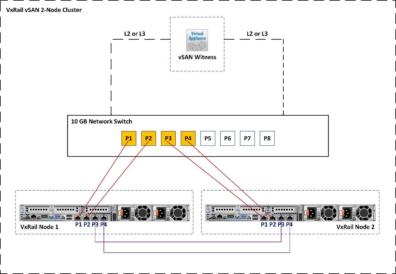
Figure 6.6 – Four 10 Gb ports in a direct-connect configuration
Now we’ll discuss another example of a direct-connect configuration. If the TOR switch is a 25 Gb network switch, the network port of each VxRail node must be 25 Gb.
In Figure 6.7, you can see four 25 Gb ports in a direct-connect configuration. There are four 25 Gb ports on each VxRail node, and the TOR switch is a 25 Gb network switch. Ports 1 and 3 (P1 and P3) of each VxRail node are connected to the network switch, and both ports are used for the management and vSAN witness networks. Ports 2 and 4 (P2 and P4) of VxRail Node 1 are directly connected to ports 2 and 4 (P2 and P4) of VxRail Node 2, and both ports are used for vSAN and vMotion networks. Two network adapters are installed on each VxRail node; one is two 25 Gb ports NDC, and the other is two 25 Gb port PCIe network adapters. This configuration can provide the hardware with the HA network adapter on each VxRail node. The VxRail network services are not interrupted if one of the hardware adapters is faulty:

Figure 6.7 – Four 25 Gb ports in a direct-connect configuration
With the previous examples in Figures 6.6 and 6.7, you’ve learned about the architecture of a direct-connect configuration. The next section will discuss switch configuration.
Switch configuration
Now, we will discuss some examples of switch configuration on a VxRail vSAN two-node cluster. In Figure 6.8, you can see four 10 Gb ports in a switch configuration with a single switch. There are four 10 Gb ports on each VxRail node, and the TOR switch is a 10 Gb network switch. Ports 1 and 2 (P1 and P2) of each VxRail node are connected to the network switch (P1 to P4), and both ports are used for the management and vSAN witness networks. Ports 3 and 4 (P3 and P4) of each VxRail node are connected to the network switch (P5 to P8); both ports are used for vSAN and vMotion networks. Cluster expansion is supported in this configuration:

Figure 6.8 – Four 10 Gb ports in a switch configuration with a single switch
Now, we will discuss another example of a switch configuration. In Figure 6.9, you can see four 10 Gb ports in a switch configuration with a dual switch; there are four 10 Gb ports on each VxRail node and two 10 Gb TOR switches, which are 10 GB Network Switch A and 10 GB Network Switch B. Ports 1 and 2 (P1 and P2) of each VxRail node are connected to 10 GB Network Switch A and B (P1 and P3), and both ports are used for the management and vSAN witness networks. Ports 3 and 4 (P3 and P4) of each VxRail node are connected to 10 GB Network Switch A and B (P2 and P4); both ports are used for vSAN and vMotion networks. In this configuration, network switches A and B have no inter-link connections:

Figure 6.9 – Four 10 Gb ports in a switch configuration with dual switch
With the previous examples in Figures 6.8 and 6.9, you have learned about the architecture of a switch configuration.
Table 6.4 shows a comparison of direct-connect and switch configurations:
|
Network Deployment Option |
Pros |
Cons |
|
Direct-connect configuration with an NDC |
Minimizes the number of network ports and network switches for the VxRail vSAN two-node cluster configuration. No network latency for vSAN and vMotion networks across VxRail nodes. |
Cluster expansion is not supported. |
|
Direct-connect configuration with an NDC and PCIe network adapter |
Minimizes the number of network ports and network switches for the VxRail vSAN two-node cluster configuration. It can provide the HA pair of network uplinks on each VxRail node. |
Cluster expansion is not supported. |
|
Single-switch configuration |
Cluster expansion is supported. Single management dashboard to monitor all network traffic. |
Increases the number of network ports and network switches for the VxRail vSAN two-node cluster configuration. |
|
Dual-switch configuration |
Cluster expansion is supported. Separate network switch managing the VxRail network service and vSAN network. |
Increases the number of network ports and network switches for the VxRail vSAN two-node cluster configuration. |
Table 6.4 – A comparison of direct-connect and switch configuration
You now understand the architecture and benefits of the direct-connect and switch configurations of a VxRail vSAN two-node cluster. When you plan to deploy the VxRail vSAN two-node cluster, you should choose the deployment option first (refer to Table 6.3), choosing whichever option is best for your environment. Then, you can choose either the direct-connect configuration or switch configuration, depending on what is suitable for your network requirements for deploying the VxRail vSAN two-node cluster.
The following section will discuss a sample configuration of a VxRail vSAN two-node cluster.
A scenario using a VxRail vSAN two-node cluster
This section will discuss a sample configuration of a VxRail vSAN two-node cluster, as shown in Figure 6.10. We will discuss a scenario of central management and witness on the VxRail vSAN two-node cluster, including network configuration and software and hardware requirements. In Figure 6.10, there are two separate locations, the Main Data Center and the Remote Office. vCenter Server and vSAN Witness are installed in the main data center, and two VxRail E660 appliances (VxRail Node 1 and VxRail Node 2) are installed in the remote office:

Figure 6.10 – Sample configuration of a VxRail vSAN two-node cluster
If you choose this deployment of the VxRail vSAN two-node cluster in this scenario, it must fulfill the following requirements:
- There are four 10 Gb ports on each VxRail E660.
- The vSAN witness and vCenter Server are installed in the main data center.
- The VLAN ID of vCenter Server and the vSAN witness must be different.
I’ve only listed the main differentiating points here. You can find the other requirements in the Overview of VxRail vSAN two-node clusters section of this chapter.
The next section will discuss the settings of vDS on a VxRail vSAN two-node cluster.
vSphere Distributed Switch
According to the configuration in Figure 6.10, VxRail will automatically create the following network groups in vDS (in Table 6.5) while deploying the VxRail vSAN two-node cluster. In this scenario, P1 to P4 are from the same network switch.
|
Network Traffic |
NIOC Shares |
VMkernel ports |
VLAN |
P1 |
P2 |
P3 |
P4 |
|
Management network |
40% |
vmk2 |
50 |
Standby |
Active |
Unused |
Unused |
|
vCenter Server management network |
N/A |
N/A |
50 |
Standby |
Active |
Unused |
Unused |
|
VxRail management network |
N/A |
vmk1 |
50 |
Standby |
Active |
Unused |
Unused |
|
vSAN network |
100% |
vmk3 |
200 |
Unused |
Unused |
Active |
Standby |
|
vMotion network |
50% |
vmk4 |
100 |
Unused |
Unused |
Standby |
Active |
|
Witness traffic |
N/A |
vmk5 |
60 |
Active |
Standby |
Unused |
Unused |
|
Virtual machines |
60% |
N/A |
N/A |
Active |
Standby |
Unused |
Unused |
Table 6.5 – The network port groups layout on the VxRail vSAN two-node cluster in Figure 6.10
A vSAN witness is a virtual appliance; it comes with two VMkernel network interfaces, vmk0 and vmk1. vmk0 is used for the management network traffic, and vmk1 is used for the vSAN network traffic. The VxRail node’s vmk5 VMkernel network interface is tagged with witness network traffic. In Figure 6.10, the VxRail node must have a static route configured for vmk5 and be able to access vmk1 on the vSAN witness. vmk1 is tagged with vSAN network traffic. The vSAN witness also has a static route configured for vmk1 and can access vmk5 on the VxRail nodes.
Ensure some incoming and outgoing firewall ports for the following services are open, as shown in Table 6.6:
|
Services |
Port |
Protocol |
To |
From |
|
vSAN Clustering Service |
12345, 23451 |
UDP |
VxRail nodes |
VxRail nodes |
|
vSAN Transport |
2233 |
TCP |
VxRail nodes |
VxRail nodes |
|
vSAN VASA Vendor Provider |
8080 |
TCP |
VxRail nodes and vCenter Server |
VxRail nodes and vCenter Server |
|
vSAN Unicast Agent to the vSAN Witness |
12321 |
UDP |
VxRail nodes and vSAN Witness |
VxRail nodes and vSAN Witness |
Table 6.6 – Service ports on VxRail appliance
Important Note
The vSAN Witness virtual appliance does not require the optional vSphere licenses. The vSphere license is hardcoded in the vSAN witness virtual appliance.
In the scenario in Figure 6.10, vCenter Server and the vSAN Witness are installed in the main data center. vCenter Server must be deployed before you deploy the VxRail vSAN two-node cluster. This vCenter Server version must be 6.7 Update 1 or later. The next section will discuss the external vCenter Server settings.
External vCenter Server
In the previous section, we already mentioned that VxRail vSAN two-node clusters only support the external vCenter Server. Before deploying a VxRail vSAN two-node cluster, you need to check the VxRail and external vCenter interoperability matrix in Figure 6.11 and make sure the VxRail software edition can support the external vCenter Server. You can find more information at this link: https://www.dell.com/support/kbdoc/en-us/000157682/vxrail-vxrail-and-external-vcenter-interoperability-matrix.
In this interoperability matrix, you can verify the compatibility of a VxRail software release and the external vCenter Server version:

Figure 6.11 – VxRail and external vCenter interoperability matrix; this information is copyright of Dell Technologies
Now, we will discuss a supported and unsupported configuration of the external vCenter Server on a VxRail vSAN two-node cluster.
Supported configuration
If VxRail comes with VxRail release 7.0.240, and the external vCenter Server version is 7.0 Update 2, according to the external vCenter interoperability matrix, it is a supported configuration.
Unsupported configuration
If the VxRail Appliance comes with VxRail release 7.0.320, and the external vCenter Server version is 7.0 Update 1c (7.0.1.00200), you should upgrade the external vCenter Server version to 7.0 U3c or later before deploying the VxRail vSAN two-node cluster; otherwise, it is an unsupported configuration.
Important Note
If you want more information on VMware vCenter build numbers and versions, you can find the details on this KB page: https://kb.vmware.com/s/article/2143838.
You have now learned about the network configuration, as well as software and hardware requirements for a VxRail vSAN two-node cluster. The next section will discuss failover scenarios of a VxRail vSAN two-node cluster.
Failure scenarios of a VxRail vSAN two-node cluster
This section will discuss some failure scenarios of a VxRail vSAN two-node cluster. The virtual machines allocated on the VxRail vSAN two-node cluster trigger different behavior when any hardware failure (for example, to the VxRail node, vSAN witness, HDD, or network uplinks) exists in the cluster. In Figure 6.12, there are four virtual machines (VM A/B/C/D) running on this VxRail vSAN two-node cluster. VMs A and B are allocated on Fault Domain 1, and VMs C and D are allocated on Fault Domain 2. A disk group (one SSD cache and three HDDs) is created on each VxRail node:

Figure 6.12 – The VxRail vSAN two-node cluster
The next section will discuss the four failover scenarios, including FD hardware failures, a faulty vSAN witness, disconnected network uplinks, and HDD failures.
Scenario one
In Figure 6.13, what status will the virtual machines trigger if VxRail Node 2 is faulty in the VxRail vSAN two-node cluster?

Figure 6.13 – VxRail Node 2 is faulty in the VxRail vSAN two-node cluster
VMs A and B keep running, but VMs C and D will shut down and trigger the HA Restart in VxRail Node 1. This is a normal hardware failure case; it will trigger the vSphere HA.
Scenario two
In Figure 6.14, what status will the VMs trigger if the vSAN communication is disconnected between VxRail Node 1 and VxRail Node 2?

Figure 6.14 – The vSAN communication is disconnected between VxRail Node 1 and VxRail Node 2
VMs A and B keep running, but VMs C and D will shut down and trigger the HA Restart in VxRail Node 1. It is a split-brain scenario in a vSAN stretched cluster. When the data nodes (VxRail Node 1 and VxRail Node 2) cannot communicate and the vSAN witness is available, the VMs allocated on Fault Domain 2 (Secondary) will shut down once and restart in Fault Domain 1 (Preferred).
Scenario three
In Figure 6.15, what status will the virtual machines trigger if the communication between a vSAN witness and two VxRail nodes is disconnected?

Figure 6.15 – The communication between the vSAN witness and two VxRail nodes is disconnected
All virtual machines (VM A/B/C/D) keep running in the VxRail vSAN two-node cluster because the communication of two VxRail nodes can be connected.
Scenario four
In Figure 6.16, what status will the virtual machines trigger if one HDD is faulty in the disk group on VxRail Node 1?

Figure 6.16 – The HDD is faulted on VxRail Node 1
All virtual machines (VM A/B/C/D) keep running in the VxRail vSAN two-node cluster, but some vSAN objects are degraded in VxRail Node 1. The data rebuild process will be started in the disk group after the faulty HDD is replaced on VxRail Node 1.
With the preceding failure scenarios, you learned about the different behaviors of virtual machines. Table 6.7 shows a summary of the expected results for the different failure scenarios:
|
Failure scenarios |
The expected result |
|
One of the nodes is faulty in the VxRail vSAN two-node cluster. |
The virtual machines allocated to the faulty node will shut down and restart in the standby node. |
|
The communication of two VxRail nodes is disconnected. |
The virtual machines allocated to the secondary FD will shut down and restart in the preferred FD. |
|
The communication between two VxRail nodes and the vSAN witness is disconnected. |
All virtual machines allocated on the preferred and secondary FDs keep running. |
|
The HDD is faulty on one of the VxRail nodes. |
Some of the vSAN objects are degraded in the disk group. |
Table 6.7 – The expected results for the different failure scenarios
After going through the four failure scenarios, you now understand the expected result in each scenario.
Summary
In this chapter, we provided an overview and learned about the design of a VxRail vSAN two-node cluster, including the network, hardware, and software requirements and some failure scenarios. When you plan to design a disaster recovery solution or a small-size VMware environment, the VxRail vSAN two-node cluster is a good option for you.
In the next chapter, you will learn about the design of a stretched cluster on VxRail and the best practices of this solution.
Questions
The following are a short list of review questions to help reinforce your learning and help you identify areas which require some improvement.
- Which deployment options can be supported on a VxRail vSAN two-node cluster?
- Central management and localized witness
- Central management
- Central management and witness
- Central witness
- Localized management and witness
- Localized witness
- All of the above
- Which two network configurations can be supported on a VxRail vSAN two-node cluster?
- Direct-connect configuration
- Fibre Channel configuration
- iSCSI channel configuration
- Switch configuration
- 10/25 Gb network configuration
- None of the above
- What are the minimum network ports required on a VxRail vSAN two-node cluster?
- Two 10 Gb ports
- Three 10 Gb ports
- Four 1 Gb ports
- Four 10/25 Gb ports
- Five 10 Gb ports
- Five 25 Gb ports
- Which network configurations can be supported on a VxRail vSAN two-node cluster?
- Two 1 Gb ports and two 10 Gb ports
- Four 1 Gb Gb ports
- Two 10 Gb ports and two 25 Gb ports
- Four 10 Gb ports
- Four 25 Gb ports
- All of the above
- Which VxRail software releases can support switch configuration on a VxRail vSAN two-node cluster?
- VxRail 4.7.200
- VxRail 4.7.300
- VxRail 4.7.410
- VxRail 7.0.240
- VxRail 7.0.300
- All of the above
- Which VxRail Series can support a VxRail vSAN two-node cluster?
- VxRail E-Series
- VxRail P-Series
- VxRail V-Series
- VxRail D-Series
- VxRail S-Series
- All of the above
- What is the maximum supported RTT between a VxRail vSAN two-node cluster and vSAN witness?
- 100 milliseconds
- 200 milliseconds
- 300 milliseconds
- 400 milliseconds
- 500 milliseconds
- None of the above
- Which description is true for the VxRail vSAN two-node cluster deployment central management and localized witness?
- It can provide a single management dashboard to manage all VxRail vSAN two-node clusters.
- Extra network configuration and expenditure are not required for the communication of vCenter Server and the vSAN witness.
- Optional vCenter Server licenses and hardware are not required.
- Extra software and hardware costs are required for the deployment of multiple vCenter Server vSAN witnesses, for example, an optional vCenter Server license per site.
- It cannot provide a single management dashboard to manage all VxRail vSAN two-node clusters.
- Which description is true for the VxRail vSAN two-node cluster deployment localized management and witness?
- It can provide a single management dashboard to manage all VxRail vSAN two-node clusters.
- Extra network configuration and cost are not required for the communication of vCenter Server and the vSAN witness.
- Optional vCenter Server licenses and hardware are not required.
- Extra software and hardware costs are required for the deployment of multiple vCenter Server vSAN witnesses, for example, an optional vCenter Server license per site.
- It cannot provide a single management dashboard to manage all VxRail vSAN two-node clusters.
- Which description is true for the VxRail vSAN two-node cluster deployment central management and witness?
- It can provide a single management dashboard to manage all VxRail vSAN two-node clusters.
- Extra network configuration and expenditure are not required for the communication of vCenter Server and the vSAN witness.
- Optional vCenter Server licenses and hardware are not required.
- Extra software and hardware costs are required for the deployment of multiple vCenter Server vSAN witnesses, for example, an optional vCenter Server license per site.
- It cannot provide a single management dashboard to manage all VxRail vSAN two-node clusters.
- What network port group is configured as 100% NIOC shared on vDS?
- Management network
- vSAN network
- vMotion network
- Virtual machines
- vCenter Server management network
- VxRail management network
- What behavior will the virtual machines trigger if the vSAN communication is disconnected between two VxRail nodes?
- The virtual machines keep running.
- All of the virtual machines shut down.
- The virtual machines on the preferred FD will shut down and power on the secondary FD.
- The virtual machines on the secondary FD will shut down and power on the preferred FD.
- None of the above.