
Chapter 3. Networking Components and Devices
So far this book has examined topologies, and cable types and connectors. These are all integral parts of the network. This chapter focuses on another—networking hardware. These are the physical components that make the network function. This chapter explores the networking devices you are most likely to see in today’s network environments and the function they perform. Each of these devices fulfills a specific role within a network; however, only the largest and most complex environments use all of them.
Foundation Topics: Common Network Devices
A network uses any number of network devices, which include switches, routers, bridges, firewalls, modems, access points (APs), and more. Network administrators must not only have familiarity with these devices but also must know how to configure and monitor them. In this section we explore some of the devices you will see on most networks and some specialized devices.
Hubs
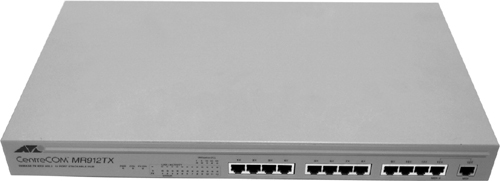
Hubs are simple network devices, and their simplicity is reflected in their low cost. Small hubs with four or five ports (often referred to as workgroup hubs) cost less than $50; with the requisite cables, they provide everything needed to create a small network. Hubs with more ports are available for networks that require greater capacity. Figure 3.1 shows an example of a workgroup hub, and Figure 3.2 shows an example of the type of hub you might see on a corporate network.
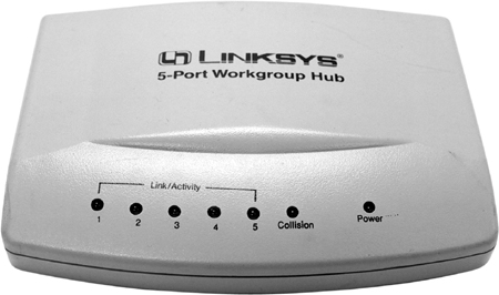
Figure 3.2 A high-capacity, or high-density, hub.
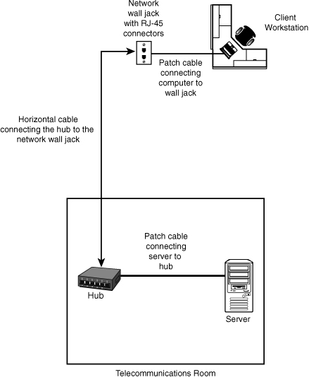
Computers connect to a hub via a length of twisted-pair cabling. In addition to ports for connecting computers, even an inexpensive hub generally has a port designated as an uplink port that enables the hub to connect to another hub to create larger networks. The “Working with Hubs and Switches” section later in this chapter presents a detailed discussion of this feature. Figure 3.3 shows how a hub connects to a client workstation.
![]()
Figure 3.3 Hub and workstation connection.
Note: Token Ring and MSAUs
Both hubs and switches are used in Ethernet networks. Token-ring networks, which are few and far between, use special devices called multistation access units (MSAU) to create the network. In some cases, MSAUs are referred to as token-ring switches; but because of the way token ring operates, these devices perform a different function from the hubs and switches discussed in this section.
Most hubs are referred to as either active or passive. Active hubs regenerate a data signal before forwarding it to all the ports on the device and require a power supply. Small workgroup hubs normally use an external power adapter, but on larger units the power supply is built in. Passive hubs, which today are seen only on older networks, do not need power and don’t regenerate the data signal.
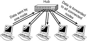
Regeneration of the signal aside, the basic function of a hub is to take data from one of the connected devices and forward it to all the other ports on the hub. This method of operation is inefficient because, in most cases, the data is intended for only one of the connected devices. Thus, the hub system of forwarding data to all devices connected to it is unnecessary. You can see a representation of how a hub works in Figure 3.4.
Note: Broadcasting
The method of sending data to all systems regardless of the intended recipient is referred to as broadcasting. On busy networks, broadcast communications can have a significant impact on overall network performance.
Because of the inefficiencies of the hub system and the constantly increasing demand for more bandwidth, hubs are all but replaced with switches. As you see in the next section, switches offer distinct advantages over hubs.
Network Switches
On the surface, a switch looks much like a hub. Despite their similar appearance, switches are far more efficient than hubs and are more desirable for today’s network environments. Figure 3.5 shows an example of a 32-port Ethernet switch. If you refer back to Figure 3.2, you notice similarities in the appearance of the high-density hub and this switch.
Figure 3.5 A 32-port Ethernet switch. (Photo courtesy TRENDware International, www.trendware.com.)
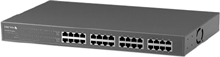
As with a hub, computers connect to a switch via a length of twisted-pair cable. Multiple switches are often interconnected to create larger networks. Despite their similarity in appearance and their identical physical connections to computers, switches offer significant operational advantages over hubs.
As discussed in the preceding section, a hub forwards data to all ports, regardless of whether the data is intended for the system connected to the port. This arrangement is inefficient; however, it requires little intelligence on the part of the hub, which is why hubs are inexpensive.
Rather than forwarding data to all the connected ports, a switch forwards data only to the port to which the destination system is connected. It looks at the Media Access Control (MAC) addresses of the devices connected to it to determine the correct port. A MAC address is a unique number stamped into every NIC. By forwarding data only to the system to which the data is addressed, the switch decreases the amount of traffic on each network link dramatically. In effect, the switch literally channels (or switches, if you prefer) data between the ports. Figure 3.6 illustrates how a switch works.
![]()
Figure 3.6 How a switch works.
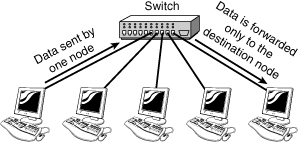
When two devices attempt to transmit at the same time on a network, collisions occur. Such collisions cause the performance of the network to degrade. By channeling data only to the connections that should receive it, switches reduce the number of collisions that happen on the network. As a result, switches provide significant performance improvements over hubs.
Switches can also further improve performance over the performance of hubs by using a mechanism called full-duplex. On a standard network connection, the communication between the system and the switch or hub is called half-duplex. In a half-duplex connection, data can be either sent or received on the wire but not at the same time. Because switches manage the data flow on the connection, a switch can operate in full-duplex mode—it can send and receive data on the connection at the same time. In a full-duplex connection, the maximum data throughput is double that for a half-duplex connection; for example, 10Mbps becomes 20Mbps, and 100Mbps becomes 200Mbps. As you can imagine, the difference in performance between a 100Mbps network connection and a 200Mbps connection is considerable.
Tip: Half-duplex
It’s important to remember that a full-duplex connection has a maximum data rate of double the standard speed, and a half-duplex connection is the standard speed. The term half-duplex can sometimes lead people to believe that the connection speed is half of the standard, which is not the case. To remember this, think of the half-duplex figure as half the full-duplex figure, not half the standard figure.
The secret of full-duplex lies in the switch. As discussed previously in this section, switches can isolate each port and effectively create a single segment for each port on the switch. Because only two devices are on each segment (the system and the switch), and because the switch is calling the shots, no collisions occur. No collisions mean no need to detect collisions; thus, a collision-detection system is not needed with switches. The switch drops the conventional carrier-sense multiple-access with collision detection (CSMA/CD) media access method and adopts a far more efficient communication method. On a network that uses CSMA/CD, when a system wants to send data to another system, it first checks to see whether the network media is free. If it doesn’t check, the network would be flooded with data, and collisions between data will occur. CSMA/CD is covered in Chapter 6, “Ethernet Networking Standards.”
Note: Microsegmentation
The process of direct communication between sender and receiver that switches perform to decrease collisions is called microsegmentation.
To use a full-duplex connection, you basically need three components: a switch, the appropriate cable, and a NIC (and driver) that supports full-duplex communication. Given these requirements, and that most modern NICs are full-duplex-ready, you might think everyone would be using full-duplex connections. However, the reality is a little different. In some cases, the NIC is not configured to operate in full-duplex mode.
Tip: Troubleshooting Network Connection Speed
Most NICs can automatically detect the speed of the network connection they are connected to. However, although the detection process is normally reliable, on some occasions it might not work correctly. If you troubleshoot a network connection and the autodetect feature is turned on, try setting the speed manually (preferably to a low speed) and then give it another go. If you use a managed switch, you might have to do the same configuration at the switch end of the connection.
Switching Methods
![]()
Switches use three methods to deal with data as it arrives:
• Cut-through—In a cut-through configuration, the switch begins to forward the packet as soon as it is received. No error checking is performed on the packet, so the packet is moved through quickly. The downside of cut-through is that because the integrity of the packet is not checked, the switch can propagate errors.
• Store-and-forward—In a store-and-forward configuration, the switch waits to receive the entire packet before beginning to forward it. It also performs basic error checking.
• Fragment-free—Building on the speed advantages of cut-through switching, fragment-free switching works by reading only the part of the packet that enables it to identify fragments of a transmission.
As you might expect, the store-and-forward process takes longer than the cut-through method, but it is more reliable. In addition, the delay caused by store-and-forward switching increases with the packet size. The delay caused by cut-through switching is always the same—only the address portion of the packet is read, and this is always the same size, regardless of the size of the data packet. The difference in delay between the two protocols is high. On average, cut-through switching is 30 times faster than store-and-forward switching.
It might seem that cut-through switching is the obvious choice, but today’s switches are fast enough to use store-and-forward switching and still deliver high performance. On some managed switches, you can select the switching method you want to use.
Note: Latency
Latency refers to the delay in communication between a sending and receiving device. Some communications have a short latency, whereas communication of others, such as a base station dish and a satellite, can have a long latency. The higher the latency, the bigger the delay in sending the data.
Advanced Switch Features
As mentioned previously, switches are more complex than hubs. Today’s switches do far more than the switches of just a few years ago. In this section we look at a few of the more advanced features that switches perform.
Power over Ethernet (PoE)
The purpose of Power over Ethernet (PoE) is described in the name. Essentially, PoE is a technology that enables electrical power to be transmitted over twisted-pair Ethernet cable. The power is transferred, along with data, to provide power to remote devices. These devices can include remote switches, wireless access points, Voice over IP (VoIP) equipment, and more.
One of the key advantages of PoE is the centralized management of power. For instance, without PoE, all remote devices need to be powered independently. In the case of a power outage, each of these devices requires an uninterruptible power supply (UPS) to continue operation. A UPS is a battery pack that enables devices to operate for a period of time. With PoE supplying power, a UPS is required only in the main facility. In addition, centralized power management enables administrators to power up or power down remote equipment.
Note: VLAN and Spanning Tree
VLAN and spanning tree were outlined in the CompTIA objectives for this chapter. VLANs, however, are discussed in Chapter 1, “Introduction to Computer Networking,” and Chapter 11, “Troubleshooting Procedures and Best Practices,” and the Spanning Tree Protocol is discussed later in this chapter along with the discussion of routers.
Trunking
In computer networking, the term trunking refers to the use of multiple network cables or ports in parallel to increase the link speed beyond the limits of any one single cable or port. Sound confusing? Those who have network experience might have heard the term link aggregation, which is essentially the same concept and refers to using multiple cables to increase the throughput. The higher capacity trunking link is used to connect switches to form larger networks.
Port Mirroring
As you might imagine, administrators need a way to monitor network traffic and monitor how well a switch is working. This is the function of port mirroring. To use port mirroring, administrators configure a copy of all inbound and outbound traffic to go to a certain port. A protocol analyzer is used to examine the data sent to the port and therefore is not interrupting the flow of regular traffic.
Tip: Port Mirroring
Remember for the exam that port mirroring enables administrators to monitor the traffic outbound and inbound to the switch.
Port Authentication
As the name implies, port authentication is authenticating users on a port-by-port basis. One standard that specifies port authentication is the 802.1X standard often associated with wireless security. Systems that attempt to connect to a LAN port must be authenticated. Those systems authenticated can access the LAN, and those that are not authenticated get no further. More information on the 802.1X standard and port authentication is in Chapter 7, “Wireless Networking.”
Working with Hubs and Switches
Despite the advantages of switches over hubs, hubs are still widely used in older networks. Whether working with hubs or switches, you need to be aware of some of their characteristics when troubleshooting a network. For instance, if performance-monitoring tools show network bottlenecks or a congested network, the hubs might need to be replaced with switches for increased performance. This is especially important when you work with both hubs and switches in a production environment.
Note: Production Environments
The term production describes a working, or live, computing environment.
Hub and Switch Ports
Hubs and switches have two types of ports: medium dependent interface (MDI) and medium dependent interface crossover (MDI-X). The two types of ports differ in their wiring. As the X implies, an MDI-X port’s wiring is crossed; this occurs because the transmit wire from the connected device must be wired to the receive line on the other. Rather than use a crossover cable, you can use the simpler straight-through cable to connect systems to the switch or hub.
Note: MDI-X or MDI
The majority of the ports on a hub/switch are normally MDI-X ports, and hosts (PCs, routers) usually come equipped with MDI ports.
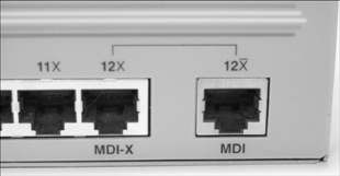
On most modern hubs and switches, a special port called the uplink port enables you to connect two hubs and switches to create larger networks. Because the aim of this type of network connection is to make each hub or switch think that it is part of a larger network, the connection for the port is not crossed; a straight-through network cable connects the two hubs or switches. When you connect ports, remember that MDI-X is crossed MDI. If there is one device with MDI port and one device with MDI-X port, a straight-through cable is required. If both are MDI ports, a crossover cable is needed. Today, however, newer switches/routers have autosense ports, which means that you can use any type of cable (crossover or straight), and it will detect and cross lines if necessary. Figure 3.7 shows the uplink port on an Ethernet switch.
Figure 3.7 The uplink port on an Ethernet switch.
Tip: Crossing Over
In the absence of an uplink port, you can connect two hubs or switches by using MDI-X ports, but you must use a crossover cable to do so.
Note: Hub Ports
Instead of having a dedicated uplink port, some switches and hubs have a port that you can change between MDI and MDI-X by pushing a button. If you use the port to connect a computer, make sure that it is set to MDI-X. If you connect to another hub or switch, make sure that it’s set to MDI.
Hubs and switches are sometimes equipped with a network connection for another cable type, such as coaxial. Switches that accommodate different media types, such as fiber-optic cable and UTP, are called hybrid switches. Other higher-end devices have empty sockets into which you can plug connectivity modules of choice. This approach enables you to create fast networks. For example, three 24-port 10/100 Ethernet switches could be connected to each other by a Gigabit Ethernet fiber-optic connection. This would create a fast network structure in which switch-to-system communication can occur at 200Mbps (in full-duplex mode) and switch-to-switch communication can occur at Gigabit Ethernet speeds. The result is a fast local area network (LAN).
Tip: Switches—Read the Label
Switches are often labeled as 10/100/1000Mbps switches. This label normally means that the ports on the switch can operate at 10Mbps, 100Mbps, or 1000Mbps. Don’t take it for granted, though. Some older switches have 10Mbps ports for connecting systems and 100Mbps ports for uplinking. Because no guidelines exist for labeling devices, some of those older switches are referred to as 10/100/1000 switches. Always check the specifications before buying a switch.
Hub and Switch Indicator Lights
Both hubs and switches use light-emitting diodes (LEDs) to indicate certain connection conditions. A link light on the hub indicates the existence of a live connection. On higher-end devices, additional lights might indicate activity, the speed of the connection, whether the connection is at half- or full-duplex, and sometimes errors or collisions. The LEDs provide an immediate visual indicator about the status of the device, so familiarizing yourself with their function is a worthwhile exercise.
Rack-Mount, Stackable, and Freestanding Devices
Some hubs and switches, and many other networking devices, are designed to be placed in a rack, whereas others are labeled as stackable or freestanding. Rack-mount devices are designed for placement into equipment racks, which are a common sight in computer rooms. The racks are approximately 19 inches wide; devices designed to be rack mounted are slightly smaller than freestanding devices so they can fit in the racks. Small metal brackets are screwed to the sides of the devices to enable them to be fitted into the racks.
If you don’t have racks, you need to use stackable or freestanding devices. These devices can literally be placed on top of one another. Many network equipment manufacturers realize that not everyone has racks, and make their equipment usable in either a rack or a freestanding configuration.
Managed Hubs and Switches
Both hubs and switches come in managed and unmanaged versions. A managed device has an interface through which it can be configured to perform certain special functions. For example, it might enable for port mirroring, which can be useful for network monitoring, or enable ports to be specified to operate at a certain speed. Because of the extra functionality of a managed device, and because of the additional components required to achieve it, managed devices are considerably more expensive than unmanaged devices. When you specify switches or hubs, consider the need for manageability carefully. If a switch will be used to connect servers to the network, a managed device might make the most sense—the extra functionality might come in handy. On parts of the network that accommodate client computers, unmanaged devices generally suffice.
Note: Port Density
Excluding the small workgroup hubs, hubs and switches normally have 8, 16, 24, or 32 ports each, although variations are available. To help you compare prices between devices, manufacturers often quote a price per port. In some cases, a higher-density device with more ports can cost significantly less per port than a device with fewer ports.
At this time, switches are still more expensive than hubs with equivalent capacity, but the gap is narrowing quickly. Some manufacturers have stopped producing hubs and instead are putting all their efforts into developing switches. This would seem to be a sound strategy. In all but the smallest networks or companies with the most restrictive budgets, hubs are obsolete. In new implementations, hubs are unlikely to be specified and installed.
Repeaters
As mentioned in Chapter 2, “Media and Connectors,” data signals weaken as they travel down a particular media. This is known as attenuation. To increase the distance a signal can travel, we can use repeaters. Repeaters increase the usable length of the cable and are commonly used with coaxial network configurations. Because coaxial networks have now fallen out of favor, and because the functionality of repeaters has been built in to other devices, such as hubs and switches, repeaters are rarely used independently.
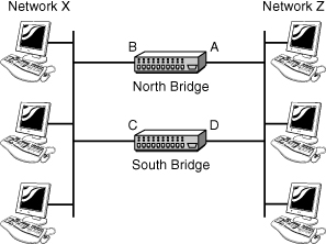
Bridges
Bridges are networking devices that connect networks. Sometimes it is necessary to divide networks into segments to reduce the amount of traffic on each larger subnet or for security reasons. When divided, the bridge connects the two subnets and manages the traffic flow between them. Today, network switches have largely replaced bridges.
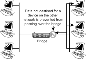
A bridge functions by blocking or forwarding data, based on the destination MAC address written into each frame of data. If the bridge believes the destination address is on a network other than that from which the data was received, it can forward the data to the other networks to which it is connected. If the address is not on the other side of the bridge, the data is blocked from passing. Bridges “learn” the MAC addresses of devices on connected networks by “listening” to network traffic and recording the network from which the traffic originates. Figure 3.8 shows a representation of a bridge.
![]()
Figure 3.8 How a bridge works.
Note: Manual Bridge Configuration
Some early bridge implementations required you to manually enter the information for each device on the network. Fortunately, bridges are now of the learning variety, and manual configuration is no longer necessary.
The advantages of bridges are simple and significant. By preventing unnecessary traffic from crossing onto other network segments, a bridge can dramatically reduce the amount of network traffic on a segment. Bridges also make it possible to isolate a busy network from a not-so-busy one, thereby preventing pollution from busy nodes.
Bridge Implementation Considerations
Although implementing bridges can offer huge improvements in performance, you must factor in a number of considerations. The first is bridge placement. Generally, you should follow the 80/20 rule for bridge placement: 80% of the traffic should not cross the bridge; that is, it should be local traffic. Only 20% of the traffic should cross a bridge to another segment. The rule is easy to understand, but accurately determining the correct location for the bridge to accommodate the rule is another matter.
Another, potentially more serious, consideration is bridging loops, which can be created when more than one bridge is used on a network. Multiple bridges can provide fault tolerance or improve performance. Bridging loops occur when multiple bridges become confused about where devices are on the network.
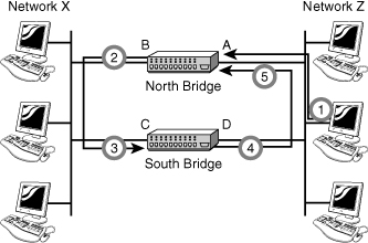
As an example of bridging loops, imagine that you have a network with two bridges, as depicted in Figure 3.9. During the learning process, the following steps occur, as shown in Figure 3.10:
1. The north bridge receives a packet from Interface A and determines that it is for a system that is not on Network Z.
2. The bridge forwards the packet to Network X.
3. Now the south bridge sees a packet originating on Network X on Interface C.
4. Because the south bridge thinks the destination system is not on Network X, it forwards the packet to Network Z.
5. The north bridge picks up the packet from Network Z. The north bridge determines that the destination system is not on Network Z, so it forwards the packet to Network X, and the whole process begins again.
Figure 3.9 A network with two bridges.
![]()
Spanning Tree Protocol (STP) is used with network bridges and switches and with the help of the spanning-tree algorithm (STA) avoids or eliminate loops on a Layer 2 network.
Note: Layer 2?
As a heads up, when we talk about STP, we talk about Layer 2 of the OSI model, and both bridges and switches work at Layer 2. Routers work at Layer 3. The OSI model and how it relates to network hardware is reviewed in Chapter 9, “OSI Model.”
The STA enables a bridge or switch to dynamically work around loops in a network’s topology. Both STA and STP were developed to prevent loops in the network and provide a way to route around any failed network bridge or ports. If the network topology changes, or if a switch port or bridge fails, STA creates a new spanning tree, notifies the other bridges of the problem, and routes around it. STP is the protocol, and STA is the algorithm STP uses to correct loops.
If a problem occurs with a particular port, the STP protocol can perform a number of actions, including blocking the port, disabling the port, or forwarding data destined for that port to another port. It does this to ensure that no redundant links or paths are found in the spanning tree and that only a single active path exists between any two network nodes.
STP uses bridge protocol data units (BPDUs) to identify the status of ports and bridges across the network. BPDUs are simple data messages exchanged between switches and contain information on ports and provide status of those ports to other switches. If BPDU messages finds a loop in the network, they are managed by shutting down a particular port or bridge interface.
Redundant paths and potential loops can be avoided within ports in several ways:
• Blocking—A blocked port will accept BDPU messages but will not forward those messages on.
• Disabled—The port is offline and does not accept BPDU messages.
• Forwarding—The port is part of the active spanning-tree topology and will forward BPDU messages to other switches.
• Learning—In a learning state, the port is not part of the active spanning-tree topology but can take over if another port fails. Learning ports receive BPDUs and identify changes to the topology when made.
• Listening—A listening port receives BPDU messages and monitors for changes to the network topology.
Most of the time, ports will be either in forwarding or blocked states. When a disruption occurs to the topology or a bridge or switch fails for some reason, listening and learning states will be used.
Note: STP
STP is defined in the IEEE 802.1d standard. IEEE and related standards are discussed in Chapter 6.
Types of Bridges
Three types of bridges are used in networks. You don’t need detailed knowledge of how each bridge works, but you should have an overview:
• Transparent bridge—Invisible to the other devices on the network. Transparent bridges perform only the function of blocking or forwarding data based on the MAC address; the devices on the network are oblivious to these bridges’ existence. Transparent bridges are by far the most popular types of bridges.
• Translational bridge—Converts from one networking system to another. As you might have guessed, it translates the data it receives. Translational bridges are useful for connecting two different networks, such as Ethernet and token-ring networks. Depending on the direction of travel, a translational bridge can add or remove information and fields from the frame as needed.
• Source-route bridge—Designed by IBM for use on token-ring networks. The source-route bridge derives its name from the fact that the entire route of the frame is embedded within the frame. This enables the bridge to make specific decisions about how the frame should be forwarded through the network. The diminishing popularity of token ring makes the chances that you’ll work with a source-route bridge slim.
Note: Identify the Bridge
On the Network+ exam, you might be asked to identify the purpose of a certain type of bridge.
As switches become ever cheaper, bridges have been overtaken by switches in terms of functionality and performance. Expect to be working with switches more often than with bridges.
Routers
Routers are an increasingly common sight in any network environment, including a small home office that uses one to connect to an ISP and a corporate IT environment where racks of routers manage data communication with disparate remote sites. Routers make internetworking possible, and in view of this, they warrant detailed attention.
Routers are network devices that direct data around the network. By examining data as it arrives, the router can determine the destination address for the data; then, by using tables of defined routes, the router determines the best way for the data to continue its journey. Unlike bridges and switches, which use the hardware-configured MAC address to determine the destination of the data, routers use the software-configured network address to make decisions. This approach makes routers more functional than bridges or switches, and it also makes them more complex because they have to work harder to determine the information.
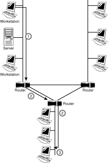
The following steps explain the basic function of a router, as illustrated in Figure 3.11:
1. Data is sent to the router.
2. The router determines the destination address and forwards it to the next step in the journey.
3. The data reaches its destination.
Figure 3.11 The basic function of a router.
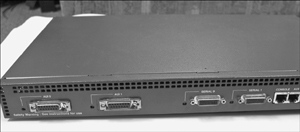
The basic requirement for a router is that it must have at least two network interfaces. If they are LAN interfaces, the router can manage and route the information between two LAN segments. More commonly, a router provides connectivity across wide area network (WAN) links. Figure 3.12 shows a router with two LAN ports (marked AUI 0 and AUI 1) and two WAN ports (marked Serial 0 and Serial 1). This router can route data between two LAN segments and two WAN segments.
Figure 3.12 A router with two LAN ports and two WAN ports.
A router can be either a dedicated hardware device or a server system that has at least two network interfaces installed in it. As part of their functionality, all common network operating systems offer the capability to act as routers.
Dedicated hardware routers offer greater performance levels than server-based solutions, but they have the disadvantage of offering a limited range of features for their cost. However, the attraction of a dedicated hardware device often outweighs this factor.
The following are some of the advantages of dedicated hardware routers:
• Typically faster than server-based routers
• Generally more reliable than server-based routers
• Easier to harden against attacks than server-based routing solutions
The following are some of the disadvantages of dedicated hardware routers:
• More expensive than server-based router solutions; extra functionality might need to be purchased.
• Often require specialized skills and knowledge to manage them.
• Limited to a small range of possible uses.
The capabilities of a router depend on the features it has. A basic router might route only one protocol between two network interfaces of the same type. A more advanced router can act as a gateway between two networks and two protocols. In addition, it can offer firewall services, security and authentication, or remote access functionality such as virtual private networking.
Note: Brouters
A brouter is a device that routes traffic that can be routed and bridges anything that cannot be routed. Because bridges have been replaced by the more flexible routers, brouters have also fallen out of favor.
The topic of routing is complex, and the routing information provided in this chapter is the most basic of tutorials. Chapter 5, “TCP/IP Routing and Addressing,” expands the discussion of routers by describing the protocols that routers use. Although this book describes the aspects of routing that you need to know for the exam, you should seek out further sources of information if you work with routers on a daily basis.
Gateways
The term gateway is applied to any device, system, or software application that can perform the function of translating data from one format to another. The key feature of a gateway is that it converts the format of the data, not the data itself.
Note: Gateways Versus Default Gateways
Don’t confuse gateways, which are discussed in this section, with default gateways, which are discussed in Chapter 5. The two perform different roles on a network.
Software gateways can be found everywhere. Many companies use an email system such as Microsoft Exchange or Novell GroupWise. These systems transmit mail internally in a certain format. When email needs to be sent across the Internet to users using a different email system, the email must be converted to another format, usually to Simple Mail Transfer Protocol (SMTP). This conversion process is performed by a software gateway.
Another good (and often used) example of a gateway involves the Systems Network Architecture (SNA) gateway, which converts the data format used on a PC to that used on an IBM mainframe or minicomputer. A system that acts as an SNA gateway sits between the client PC, and the mainframe and translates requests and replies from both directions. Figure 3.13 shows how this would work in a practical implementation.
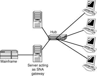
If it seems from the text in this section that we are vague about what a gateway is, it’s because there is no definite answer. The function of a gateway is specific, but how the gateway functionality is implemented is not.
No matter what their use, gateways slow the flow of data and can therefore potentially become bottlenecks. The conversion from one data format to another takes time, and so the flow of data through a gateway is always slower than the flow of data without one.
Modems
Modem is a contraction of the terms modulator and demodulator. Modems perform a simple function: They translate digital signals from a computer into analog signals that can travel across conventional phone lines. The modem modulates the signal at the sending end and demodulates at the receiving end.
Modems provide a relatively slow method of communication. The fastest modem available on the market today has a maximum speed of 56Kbps. Compare that to the speed of a 100/1000Mbps network connection, and you’ll find that the modem is simply to slow. Today’s modems are limited to browsing simple web pages or occasionally downloading small files but are wholly unsuitable for downloading large files and browsing heavy graphic websites. As a result, many people prefer to use other remote access methods, including ISDN, discussed in Chapter 8, “Wide Area Networking,” and cable/DSL access.
Modems are available as internal devices that plug into expansion slots in a system; external devices that plug into serial or USB ports; PCMCIA cards designed for use in laptops; and specialized devices designed for use in systems, such as handheld computers. In addition, many laptops now come with integrated modems. For large-scale modem implementations, such as at an ISP, rack-mounted modems are also available. Figure 3.14 shows an internal modem and a PCMCIA modem.
Figure 3.14 An internal modem (left) and a PCMCIA modem (right).

Modems are controlled through a series of commands known as the Hayes AT command set. Hayes was a company that, for many years, led the field in the development of modems and modem technology. The AT commands enable you to control a modem and configure and diagnose it. Table 3.1 lists some of the most commonly used AT commands.
![]()
Table 3.1 Commonly Used AT Modem Commands
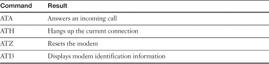
Note: Know the AT Command
On the Network+ exam, you might be asked to identify the correct AT command to be used in a given situation.
Modem Connection Speeds
The actual speed you obtain on a modem connection depends on a variety of factors, including the quality of the line you use and the speed of the modem. For example, you might find that even with a 56Kbps modem, the most you can get on a certain connection is 53Kbps. If you try the same connection again on a different phone line, you might get a higher or lower rate. Quality of the connection aside, two factors govern the maximum speed attainable by your modem: the speed of the Universal Asynchronous Receiver/Transmitter (UART) chip in your system (which controls the serial ports) and the speed of the modem.
In older systems, the UART chips were capable of only slow speeds, making them unable to keep up with fast modems. Today, most systems have UART chips capable of speeds well in excess of those offered by modems. Now the modem, not the UART chip, is the bottleneck. Table 3.2 lists the types of commonly used UART chips and their associated speeds.
Table 3.2 UART Chips and Their Associated Speeds

Modem speeds can be expressed in either baud rate or bits per second (bps). The baud rate refers to the number of times a signal changes in each second, and the bps rate is the number of bits of data that can be sent or received in a second. Although the figures are identical in some modems, in others the bps rate is higher than the baud rate. The baud rate is actually not as important, and the higher the bps figure, the better. Most modern modems offer bps rates far greater than the baud rate.
To make it easier to compare modems, standards have been created that define the data throughput of the modem and what features it provides. These are sometimes referred to as the V standards, and you can use them when buying a modem to determine the modem’s capabilities.
Network Interface Cards (NIC)
NICs—sometimes called network cards—are the mechanisms by which computers connect to a network. NICs come in all shapes and sizes, and they come in prices to suit all budgets. Consider the following when buying a NIC:
• Network compatibility—Sometimes people order the wrong type of NIC for the network. Given the prevalence of Ethernet networks, you are likely to need to specify network compatibility only when buying a NIC for another networking system.
• Bus compatibility—Newly purchased NICs will almost certainly use the Peripheral Component Interconnect Express (PCIe) bus.
• Port compatibility—Generally a NIC has only one port, for twisted-pair cabling. If you want some other connectivity, you need to be sure to specify your card accordingly; for example, you might need a fiber-optic or coaxial cable port.
Note: Combo Cards
Sometimes a NIC has a twisted-pair socket, a coaxial connector, and an attachment unit interface (AUI) port. These cards are referred to as combo cards. Today, the dominance of twisted-pair cabling means that most NICs have only a twisted-pair connection.
• Hardware compatibility—Before installing a network card into a system, you must verify compatibility between the network card and the operating system on the PC in which you install the NIC. If you use good-quality network cards from a recognized manufacturer, such verification should be little more than a formality.
Note: NIC terminology
Many terms are used to refer to NICs, such as network card, network adapter, and LAN adapter. All refer to the same thing.
Types of Network Interfaces
Network interfaces come as add-in expansion cards or as PCMCIA cards used in laptop systems. In some cases, rather than have an add-in NIC, the network interface is embedded into the motherboard. Figure 3.15 shows an example of an add-in NIC. Figure 3.16 shows a PCMCIA network card, and Figure 3.17 shows a built-in network interface in a laptop system.
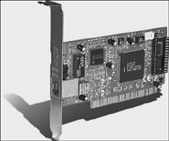

Figure 3.17 A built-in network interface on a laptop system.

Note: Combo Cards
Did you notice that the cards used in Figure 3.14 and 3.16 are the same card? This is not a mistake; the PCMCIA card is both a modem and a NIC.
A network interface typically has at least two LEDs that indicate certain conditions:
• Link light—Indicates whether a network connection exists between the card and the network. An unlit link light is an indicator that something is awry with the network cable or connection.
• Activity light—Indicates network activity. Under normal conditions, the light should flicker sporadically and often. Constant flickering might indicate a busy network or a problem somewhere on the network worth investigating.
• Speed light—Indicates that the interface is connected at a certain speed. This feature is normally found on Ethernet NICs that operate at 100Mbps/1000Mbps—and then only on certain cards.
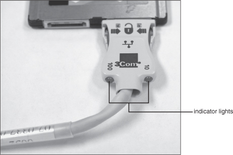
Some network cards combine the functions of certain lights by using dual-color LEDs. PCMCIA cards sometimes have no lights, or the lights are incorporated into the media adapter that comes with the card. You can see an example in Figure 3.18.
Figure 3.18 Indicator lights on a media adapter for a PCMCIA NIC.
Installing Network Cards
At some point in your networking career, it is likely that you will have to install a NIC into a system. For that reason, an understanding of the procedures and considerations related to NIC installations is useful.
Tip: Avoid ESD
When installing any component in a system, you need to observe proper and correct procedures to guard against electrostatic discharge (ESD). ESD can cause components to fail immediately or degrade so that it fails at some point in the future. Proper ESD precautions include wearing an antistatic wrist strap and properly grounding yourself.
Here are some of the main points to consider:
• Drivers—Almost every NIC is supplied with a driver disk, but the likelihood of the drivers on the disk being the latest drivers is slim. Always make sure that you have the latest drivers by visiting the website of the NIC manufacturer. The drivers play an important role in the correct functioning of the NIC, so spend a few extra minutes to make sure that the drivers are installed and configured correctly.
• NIC configuration utilities—In days gone by, NICs were configured with small groups of pins known as jumpers, or with small plastic blocks of switches known as dip switches. Unless you work with old equipment, you are unlikely to encounter dip switches. Although these methods were efficient and easy to use, they have now largely been abandoned in favor of software configuration utilities, which enable you to configure the settings for the card (if any) and to test whether the card works properly. Other utilities can be used through the operating system to obtain statistical information, help, and a range of other features.
• System resources—To function correctly, NICs must have certain system resources allocated to them: the interrupt request (IRQ) and memory addresses. In some cases, you might need to assign the values for these manually. In most cases, you can rely on plug-and-play, which assigns resources for devices automatically and even the software driver needed to make the hardware work with the operating system.
• Physical slot availability—Most modern PCs have at least three or four usable expansion slots. Not only that, but the increasing trend toward component integration on the motherboard means that devices such as serial and parallel ports and sound cards are now built in to the system board and therefore don’t use up valuable slots. If you work on older systems or systems that have a lot of add-in hardware, you might be short of slots. Check to make sure that a slot is available before you begin.
• Built-in network interfaces—A built-in network interface is a double-edged sword. The upsides are that it doesn’t occupy an expansion slot, and hardware compatibility with the rest of the system is almost guaranteed. The downside is that a built-in component is not upgradeable. For this reason, you might find install an add-in NIC and at the same time disable the onboard network interface. Disabling the onboard interface is normally a straightforward process, achieved by going into the BIOS setup screen or, on some systems, a system configuration utility. In either case, consult the documentation that came with the system or look for information on the manufacturer’s website.
As time goes on, NIC and operating system manufacturers are making it increasingly easy to install NICs in systems of all sorts and sizes. By understanding the requirements of the card and the correct installation procedure, you should install cards simply and efficiently.
Media Converters
Network technologies change at a rapid pace, and administrators are always on the lookout to find cost-effective ways to increase network performance. The demand for higher speeds and greater distances keeps us, as administrators, on our toes. The process of incorporating new technology with older infrastructure is made easier with media converters.
Network media converters interconnect different types of cables within an existing network. For example, the media converter connects newer Gigabit Ethernet technologies with older 100BaseT networks.
This ability to combine networks, increases networking flexibility, while decreasing the cost of having to retrofit the network to accommodate new technology. Converters come in many shapes and sizes to connect to a variety of networks. This includes coax, twisted-pair, single-mode, or multimode fiber. Converters can be designed to work with any network type, including Ethernet, Fast Ethernet, Gigabit Ethernet, Asynchronous Transfer Mode (ATM), fiber distributed data interface (FDDI), and token ring.
Tip: Converters
By using media converters, companies do not need to dismantle the current wiring infrastructures. Media converters enable us to use existing infrastructure while keeping pace with changing technologies.
Firewalls
Today, firewalls are an essential part of a network’s design. A firewall is a networking device, either hardware- or software-based, that controls access to your organization’s network. This controlled access is designed to protect data and resources from outside threats. To do this, firewalls are typically placed at entry/exit points of a network. For example, a firewall might be placed between an internal network and the Internet. After the firewall is in place, it can control access in and out of that point.
Although firewalls typically protect internal networks from public networks, they also control access between specific network segments within a network. For example, you might place a firewall between the accounts department and the sales department segments of the network.
As mentioned, firewalls can be implemented through software or through a dedicated hardware device. Organizations implement software firewalls through network operating systems (NOS) such as Linux/UNIX, Windows servers, and Mac OS servers. The firewall is configured on the server to enable or permit certain types of network traffic. In small offices and for regular home use, a firewall is commonly installed on the local system and configured to control traffic. Many third-party firewalls are available.
Hardware firewalls are used in networks of all sizes today. Hardware firewalls are often dedicated network devices that you can implement with little configuration and use to protect all systems behind it from outside sources. Hardware firewalls are readily available and often combined with other devices. For example, many broadband routers and wireless APs have firewall functionality built in. In such a case, the router or AP might have a number of ports available to plug systems into.
You can find a complete discussion of firewalls in Chapter 14, “Network Access Security.”
DHCP Server
Without question, the easiest way to assign TCP/IP information to client systems is to use a Dynamic Host Configuration Protocol (DHCP) server. On a network running TCP/IP, each computer must have a unique IP address to be recognized and be part of the network. Briefly, a protocol is a method of communicating between computers.
Computers on a network using TCP/IP require specific network settings to connect to the network. First among these settings is the IP address. An IPv4 address consists of four octets, or four sets of 8 bits—represented in decimal form—for example, 192.168.2.1. Each computer on the network must have one of these numbers to perform network functions through TCP/IP. The number must be unique to the PC and must be within a certain range to enable the PC to connect to other systems. A complete discussion of TCP/IP and addressing is covered in Chapter 5.
There was a time when all IP addresses were entered manually into the network settings of each client workstation. Manually set, or static, IP addresses are difficult to maintain in large networks. Adding to the time it takes to individually set the IP addresses is that each address must be unique. Duplicate IP addresses prevent a successful connection to the network for the second system to log on with the duplicate IP address. All network services will be unavailable to the workstations that logs on second. When you set static IP addresses, it is essential to track assigned IP addresses carefully to prevent duplicating addresses and to make future expansion and troubleshooting easier.
In larger networks, the assignment of manual addresses can be a nightmare, especially when IP addressing schemes can be changed and computers can be moved, retired, or replaced. That’s where DHCP comes in. DHCP does the job of assigning IP addresses, eliminating the need to assign IP addresses individually and making the job of network administrators considerably easier. When a DHCP server runs on a network, the workstation boots up and requests an IP address from the server. The server responds to the request and automatically assigns an IP address to the computer for a given period of time, known as a lease. The workstation acknowledges the reception of the IP address, and the workstation has all the information it needs to become part of the network. This communication between the server and the workstation happens completely automatically and is invisible to the computer user.
Because of their capability to efficiently distribute IP addresses to network workstations, DHCP servers are widely used in client/server environments. People working with networks will most certainly encounter DHCP servers. The critical nature of DHCP services means that companies often choose to run more than one DHCP server.
Note: Where’s AP
The objectives specify a discussion of wireless access points (APs), which are covered with the rest of wireless information in Chapter 7.
Specialized Network Devices
A network is composed of many pieces of hardware. Some, such as firewalls and DHCP servers, are in most networks. Devices that are more specialized, such as load balancers and proxy servers, are not found in every network environment. CompTIA lists the devices described in the following sections as specialized networking devices. We take a quick look at what they are designed to do.
Multilayer and Content Switches
It used to be that networking devices and the function they perform were separate. We had bridges, routers, hubs, and more, but they were separate devices. Over time, the functions of some individual network devices became integrated into a single device. This is true of multilayer switches.
A multilayer switch is one that can operate at both the Layer 2 and Layer 3 of the OSI model. The OSI model is covered in Chapter 9, but for now, this means that the multilayer device can operate both as a switch and as a router. Also known as a Layer 3 switch, the multilayer switch is a high-performance device that actually supports the same routing protocols that routers do. It is a regular switch directing traffic within the LAN, but it can forward packets between subnets as well.
Note: 2 for 1
A multilayer switch operates as both a router and a switch.
A content switch is another specialized device. A content switch is not as common on today’s networks, mostly because of cost. A content switch examines the network data it receives, decides where the content is intended to go, and forwards it there. The content switch has the capability to identify the application that data is targeted for by associating it with a port. For example, if data is using the SMTP port, the data could be forwarded to an SMTP server.
Content servers can help with load balancing because they can distribute requests across servers and target data only to the servers needing the data, or distribute data between application servers. For example, if multiple mail servers are used, the content switch can distribute requests between the servers, thereby sharing the load evenly. This is why the content switch is sometimes referred to as a load-balancing switch.
Note: Content Switching
A content switch can distribute incoming data to specific application servers and help distribute the load.
Intrusion Detection and Prevention Systems
Administrators can use several methods to help secure the network. In addition to a firewall, an intrusion detection system (IDS) and intrusion prevention system (IPS) can be used. Both are designed to help identify unwanted network access and traffic, but they work in slightly different ways.
An IDS is either a hardware or software device that constantly monitors inbound and outbound network traffic. The IDS uses built-in parameters to flag and document any traffic it determines to be suspicious or potentially dangerous. But that is where the IDS stops. It does not actively try to manage the threat; rather, it identifies the threat and then the administrator must monitor the IDS system to see what the problem might be. Although it doesn’t try to fix the potential threat, the IDS can be configured to send an alert, notifying the administrator of a potential threat and security breach.
In operation, an IDS system compares the inbound and outbound traffic to a large database of attack signatures. Attack signatures are known elements of a particular attack. Just as we have fingerprints, certain attacks can be identified by their features. In this way, the IDS system can identify attacks that have already been identified elsewhere and can pinpoint them entering or leaving the network. An IDS system is only as good as the database it uses to identify attacks, which makes it important to keep the database up to date.
An IDS system can be deployed as host-based (resident to a single system) or network-based (watches all network traffic). In either case, an IDS system cannot replace a firewall because it has different functions. The firewall monitors secures access between two networks, such as a business and the Internet, and prevents unwanted traffic from entering the network. The IDS system inspects an intrusion after it has taken place—that is, after it has passed the firewall. An IDS also watches for threats from within the network, whereas the firewall operates on the network perimeter.
An IDS system looks to flag potential threats. In contrast, the IPS is more proactive and tries to manage them on its own. Similar to an IDS, the IPS monitors both inbound and outbound traffic and looks for potential threats. But where an IDS flags and documents the threat, the IPS takes immediate action, trying to remove the threat. Where an IDS might flag a network intruder, the IPS will try to immediately shut the intruder out. The actions an IPS takes are established by the network administrator. You can find more information about IDS and IPS in Chapter 14.
Load Balancer
Network servers are the workhorses of the network. We rely on them to hold and distribute data, maintain backups, secure network communications, and more. A single server often cannot maintain the workload. This is where load balancing comes into play. Load balancing is a technique in which the workload is distributed between several servers. This feature can increase network performance, reliability, and availability.
Note: Share the Load
Remember for the exam that load balancing increases redundancy and, therefore, availability to data.
A load balancer can be either a hardware device or software specially configured to balance the load. You can learn more about load balancing and its importance in the network in Chapter 10, “Network Performance and Optimization.”
Multifunction Network Devices
It used to be that each device on a network had its own purpose. We had a firewall, routers, repeaters, and hubs, to name a few. Multifunction network devices combine the function of these individual devices into a single unit. Let’s look at a wireless access point used by home users or small companies for wireless access to the Internet. Those of you who have experience with these devices know they are multifunction network devices. They have combined functionality, including firewall, DHCP server, wireless access point, switch, gateway, and router. One device under $100 can perform all these functions. These multifunction devices make it easier for administrators to tend to the network. Fewer devices need to be managed, and all configurations can be handled remotely.
Multifunction devices can offer some advantages over multiple independent devices or software packages. Suppose an organization maintains antivirus, firewall, content-filtering, and IDS/IPS software on a single or even on several servers. This organization must pay for the cost of the software on each of the servers the operating system, and the personnel to maintain the systems. All this can be replaced with a single multifunction network device.
DNS Server
A domain name system (DNS) server performs a basic but vital role for many organizations. The function of a DNS server is relatively simple in that it provides name resolution from hostnames to IP addresses. The measures to which the server will go to provide a successful resolution, however, are not so simple. In addition to consulting its own databases for the requested information, a DNS server also contacts other DNS servers as needed to get the necessary information. This process can involve a large number of queries.
As you might know, each device on a network requires a unique IP address so that it can provide services to clients. Rather than rely on the flawed human memory to remember these addresses, DNS enables us to use easy-to-remember hostnames, such as comptia.org, to access these hosts. When we type www.comptia.org into a web browser, our configured DNS server takes the request and searches through a system of DNS servers to find out the correct TCP/IP address that relates to www.comptia.org. After the DNS server has ascertained the correct TCP/IP address, that address is returned to the client, which then contacts the IP address directly. To speed up subsequent requests for the same address, the DNS server adds the address to its cache. For a workstation to send requests to the DNS server, the TCP/IP address of the DNS server must be provided to the workstations. This can be done manually, or the address can be included in the information supplied by a DHCP server.
Before DNS was used, resolution of hostnames to IP addresses was (and still is, in some cases) performed through static text files called Hosts files. These text files quickly became too large to manage easily and were replaced by DNS.
The function of DNS remains largely hidden from most users, but our reliance on the system is amazingly high. In January 2001, a Microsoft employee made a configuration change to one of Microsoft’s DNS servers. The change caused an error that rendered some Microsoft-hosted websites, including the popular Hotmail system, inaccessible for a number of hours. The servers were up and running, but they could not be reached.
Most common operating systems provide the capability to act as a DNS server. Some implementations are more sophisticated than others, but the basic principle of hostname-to-TCP/IP-address resolution remains the same.
The amount of computing power required by a DNS server is proportional to the number of DNS requests that it handles. Within an organization, records might be configured for only a relatively small number of hosts, and only a small number of client requests might occur. In such an environment, it would be unlikely to have a server dedicated to DNS functions. In contrast, a DNS server for an ISP would need to be powerful enough to accommodate perhaps millions of requests per hour.
Tip: DNS Server
A DNS server answers client requests to translate hostnames to IP addresses.
Bandwidth Shaper
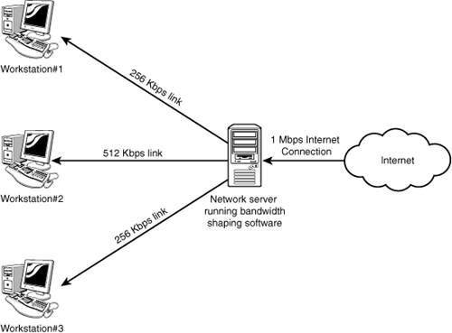
The demand for bandwidth on networks has never been higher. Internet and intranet applications demand a high amount of bandwidth. Administrators have to ensure that despite these demands, adequate bandwidth is available for mission critical applications whereas few resources are dedicated to spam or peer-to-peer downloads. To do this, we need to monitor network traffic to ensure that data flows as required.
The term bandwidth shaping describes the mechanisms used to control bandwidth usage on the network. Bandwidth shaping is typically done using software installed on a network server. From this server, administrators can control who uses bandwidth, for what, and when. Bandwidth shaping establishes priorities to data traveling to and from the Internet and within the network.
A bandwidth shaper essentially performs two key functions: monitoring and shaping. Monitoring includes identifying where bandwidth usage is high and at what time of day. After that information is obtained, administrators can customize or shape bandwidth usage for the best needs of the network. Figure 3.19 shows an example of a bandwidth shaper.
![]()
Proxy Server
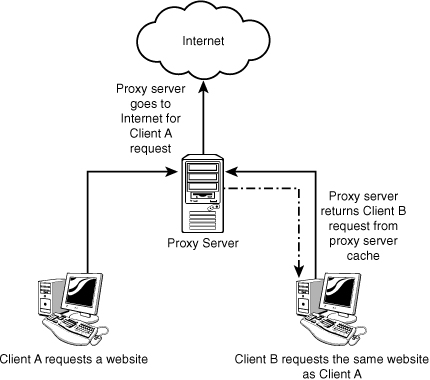
Proxy servers are typically part of a firewall system; they have become so integrated with firewalls that the distinction between the two can sometimes be lost. However, proxy servers perform a unique role in the network environment—a role that is separate from that of a firewall. For the purposes of this book, a proxy server is defined as a server that sits between a client computer and the Internet, looking at the web page requests sent by the client. For example, if a client computer wants to access a web page, the request is sent to the proxy server rather than directly to the Internet. The proxy server first determines whether the request is intended for the Internet or for a web server locally. If the request is intended for the Internet, the proxy server sends the request out as if it had originated the request. When the information is returned by the Internet web server, the proxy server returns the information to the client.
Although a delay might be induced by the extra step of going through the proxy server, the process is largely transparent to the client that originated the request. Because each request a client sends to the Internet is channeled through the proxy server, the proxy server can provide certain functionality over and above forwarding requests.
One feature is that proxy servers can greatly improve network performance through a process called caching. When a caching proxy server has answered a request for a web page, the server makes a copy of all or part of that page in its cache. Then, when the page is requested again, the proxy server answers the request from the cache rather than going back out to the Internet. For example, if a client on a network requests the web page www.comptia.org, the proxy server can cache the contents of that web page. When a second client computer on the network attempts to access the same site, that client can retrieve it from the proxy server cache, and accessing the Internet is not necessary. This greatly increases the response time to the client and can significantly reduce the bandwidth needed to fulfill client requests. An example of this is shown in Figure 3.20.
Nowadays, speed is everything, and the capability to quickly access information from the Internet is a crucial concern for some organizations. Proxy servers and their capability to cache web content accommodate this need for speed.
An example of this speed might be found in a classroom. If a teacher asks 30 students to access a specific URL (Uniform Resource Locator), without a proxy server, all 30 requests are sent into cyberspace and subjected to the delays or other issues that can arise. The classroom scene with a proxy server is quite different. Only 1 request of the 30 finds its way to the Internet; the other 29 are filled by the proxy server’s cache. Web page retrieval can be almost instantaneous.
However, caching has one potential drawback. When you log on to the Internet, you get the latest information, but this is not always so when information is retrieved from a cache. For some web pages, it is necessary to go directly to the Internet to ensure that the information is up to date.
Another key feature of proxy servers is that network administrators have the ability to filter client requests. If a server administrator wants to block access to certain websites, a proxy server enables this control, making it easy to completely disallow access to some websites. If you find it necessary to block out numerous websites, however, the job of maintaining proxy servers gets a little more complicated.
Determining which websites users can or cannot access is typically done through something called an access control list (ACL). The ACL is a list of allowable or nonallowed websites. As you might imagine, compiling such a list can be a monumental task. Given that millions of websites exist and new ones are created daily, how would it be possible to target and disallow access to the “questionable” ones? One approach is to reverse the situation and deny access to all pages except those that appear in an “allowed” list. This approach has a high administrative overhead and can greatly limit the productive benefits available from Internet access.
Understandably, it is impossible to maintain a list that contains the locations of all sites that contain questionable content. In fairness, that is not what proxy servers were designed to do. However, by maintaining a list, proxy servers are better able to provide a greater level of control than that of an open system, and along the way, they can make the retrieval of web pages far more efficient.
CSUs/DSUs
A Channel Service Unit/Data Service Unit (CSU/DSU) acts as a translator between the LAN data format and the WAN data format. Such a conversion is necessary because the technologies used on WAN links are different from those used on LANs. Some consider a CSU/DSU as a type of digital modem; but unlike a normal modem, which changes the signal from digital to analog, a CSU/DSU changes the signal from one digital format to another. Figure 3.21 shows how a CSU/DSU might fit into a network.
Figure 3.21 How a CSU/DSU is used in a network.
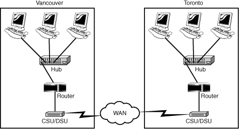
A CSU/DSU has physical connections for the LAN equipment, normally via a serial interface, and another connection for a WAN. Traditionally, the CSU/DSU has been in a separate box from other networking equipment; however, the increasing use of WAN links means that some router manufacturers are now including the CSU/DSU functionality in routers or are providing the expansion capability to do so.
Network Devices Summary
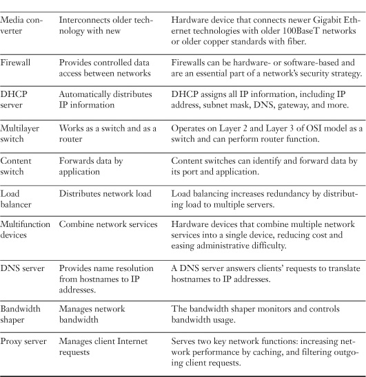
The information in this chapter is important for the Network+ exam. To summarize the coverage of network devices, we have placed some of the key points about each device in Table 3.3. You should learn this information well.
![]()
Table 3.3 Network Devices Summary

Summary
Many devices create networks. Every network except the simplest, single-segment coaxial networks uses one or more of these devices. Knowledge of the purpose of the devices discussed in this chapter is vital for the Network+ exam and for the real world.
Hubs and switches provide a mechanism to connect devices to a network created with twisted-pair cabling. Switches offer a speed advantage over hubs because they can use full-duplex communications. They also create dedicated paths between devices, reducing the number of collisions that occur. Both hubs and switches are available in managed and unmanaged varieties.
Bridges enable network traffic to be confined to certain network segments, thereby reducing the amount of network traffic. On Ethernet networks, bridges provide the additional benefit of reduced collisions.
Routers are devices that connect networks and thereby create internetworks. Because routers use software-configured network addresses instead of hardware-defined MAC addresses, they can provide more functionality than bridges. Routers either can be dedicated hardware devices or can be implemented through software on server systems.
Multilayer and content switches are listed as specialized network devices in the CompTIA objectives. Multilayer switches operate as both a switch and a router. Content switches forward data to its associated application server.
Bandwidth shapers are used on a network to manipulate how bandwidth is used. Load balancers are used to distribute the processing and data traffic between devices. It prevents network resources from being overloaded.
DNS servers are used on a network designed to resolve hostname to IP addresses. DHCP servers automatically assign IP addressing information to client systems. A gateway is a device that translates from one data format to another; it can be a hardware device or a software application. A CSU/DSU is an example of a gateway: CSUs/DSUs translate from the data format used on LANs to that used on WANs. A modem, which translates a signal from digital to analog so that it can be transmitted across a conventional phone line, is another example of a gateway.
NICs are the point of connectivity between devices and the network. NICs can be add-in expansion cards, PCMCIA devices for laptops, or devices built in to the system board.
On a network, each NIC is identified by a unique MAC address. MAC addresses are assigned by the manufacturers that produce the devices, although the high-level assignment of addresses is managed and carried out by the IEEE.
Other network devices include firewalls, converters, proxy servers, and repeaters. Firewalls protect one network from another, converters connect new and old technology, proxy servers provide caching and filtering services, and repeaters regenerate data signals to enable them to travel farther.
If you get a chance to use all the hardware devices discussed in this chapter, count yourself lucky. Almost every environment uses some of them, but few use them all.
Exam Preparation Tasks: Review All the Key Topics
![]()
Review the most important topics in the chapter, noted with the key topics icon in the outer margin of the page. Table 3.4 lists a reference of these key topics and the page numbers on which each is found.
Table 3.4 Key Topics for Chapter 3

Complete the Tables and Lists from Memory
Print a copy of Appendix B, “Memory Tables” (found on the CD), or at least the section for this chapter, and complete the tables and lists from memory. Appendix C, “Memory Tables Answer Key,” also on the CD, includes completed tables and lists to check your work.
Define Key Terms
• Hub
• Repeater
• Modem
• NIC
• Media converters
• Basic switch
• Bridge
• Access points
• Router
• Firewall
• DHCP server
• PoE
• Spanning tree
• Trunking
• Port authentication
• Multilayer switch
• Content switching
• Load balancer
• Multifunction network devices
• DNS server
• Bandwidth shaper
• Proxy server
• CSU/DSU
Apply Your Knowledge
Exercise 3.1 Determining MAC Addresses for Network Cards
This chapter identifies the characteristics and functions of network devices. In an ideal world, this project would require hands-on experience with these devices, but this is not an ideal world, and access to this equipment is not always easy. Therefore, we include two exercises that you might be required to perform if such devices are used on your network.
This project assumes that you use a Windows-based system. You need an installed NIC with a working driver.
Estimated time: 10 minutes
1. Open a command window by selecting Start, Run. In the command box, type cmd and then click OK.
2. At the command prompt, type ipconfig /all. The MAC address of your NIC is displayed in the Physical Address line.
3. Open a web browser and go to the following website: http://standards.ieee.org/regauth/oui/oui.txt.
4. Using the Find functionality in your web browser, type in the first three octets of your physical address. The find function locates the entry that corresponds with the address of your NIC. Is the manufacturer of your NIC the company you expected it to be? Some NIC manufacturers rebrand cards manufactured by another company. For that reason, the MAC address might correspond to a manufacturer that is different from the brand name of the card.
Exercise 3.2 Viewing the IP Information on Your System
In this chapter we discussed gateways, DHCP servers, and DNS servers. In this exercise we identify all of these on a client system and whether DHCP is enabled.
Estimated time: 5 minutes
1. Open a command window by selecting Start, Run. In the command box, type cmd.exe and then click OK.
2. At the command prompt, type ipconfig /all.
3. A long window of information displays. Scroll down the list; can you find the address of the default gateway? Through this device, you are routed forward to the Internet.
4. Do you see the IP address of the DNS server? The device with this IP address is responsible for converting your hostname to the IP address.
5. Finally, find the IP address of the DHCP server. If DHCP is enabled, you see the IP address of the DHCP server.
6. If you work from home using a home router for this exercise, you can put the IP address of the DHCP or DNS server into your browser. This takes you to a logon window and enables you to configure the device.
Review Questions
You can find answers to the review questions in Appendix A, “Answers to Review Questions.”
1. Several users on your network are downloading from peer-to-peer networks, tying up bandwidth during peak hours. Which of the following manages network bandwidth?
a. Load balancer
b. Load toner
c. Bandwidth toner
d. Bandwidth shaper
2. You have recently been hired as a network administrator for a large company. The company uses a multilayer switch. What is the function of the switch on the network? (Select two.)
a. Route traffic between subnets
b. Route traffic between DNS servers on the local LAN
c. Operate as a Layer 2 network switch
d. Switch data based on content
3. Which of the following technologies are responsible for answering client requests to translate hostnames to IP addresses?
a. Balancing server
b. DNS server
c. Proxy server
d. DHCP server
4. A bridge makes forwarding decisions based on what information?
a. IP address
b. MAC address
c. Binary address
d. IRQ address
5. What information does a switch use to determine the port to which data should be sent?
a. The IP address of the connected device
b. The priority of the connected device
c. The MAC address of the connected device
d. The Ethernet address of the connected device
6. Which of the following network devices performs filtering and caching web pages for client Internet requests?
a. Proxy server
b. DNS server
c. DHCP server
d. RAS server
7. Which of the following best describes the function of PoE?
a. Routes data to PPP ports
b. Provides power over twisted-pair cable
c. Increases speeds of twisted-pair cable
d. Trunks switch ports
8. What is the purpose of the uplink port on a hub or switch? (Select three)
a. It enables for satellite connections.
b. It enables hubs or switches to be connected together.
c. It enables computers to connect to the device.
d. It provides a spare port, which can be used if another port fails.
9. By what method does a router determine the destination address for a packet?
a. It looks at the MAC address of the sender.
b. It looks for the MAC address of the destination.
c. It looks for the software-configured network address for the destination.
d. It looks at the FCS field of the packet.
10. Which of the following devices was specifically designed to deal with attenuation?
a. Switch
b. Passive hub
c. DHCP server
d. Repeater
11. Which of the following are valid port states when routing with STP? (Select two.)
a. Disabled
b. Listening
c. Paused
d. Suspended
12. What is the difference between an active hub and a passive hub?
a. An active hub has management capabilities.
b. An active hub forwards the data only to the ports that need it.
c. An active hub channels bandwidth to a given connection if the connection becomes too slow.
d. An active hub regenerates the signal before forwarding it.
13. Which of the following devices is typically used to protect private internal networks from public ones?
a. DHCP server
b. Firewall
c. Active hub
d. Protective switch
14. Which of the following technologies enables power to be sent over regular UTP cable?
a. PoE
b. PoDNS
c. PoC
d. PoUTP
15. What is the maximum speed of a 16550 UART chip?
a. 64,000bps
b. 115,200bps
c. 430,800bps
d. 921,600bps
16. What is the name of the bridging method used to segregate Ethernet networks?
a. Source-route
b. Invisible
c. Cut-through
d. Transparent
17. You have been called to support a network. When you arrive, you notice that multiple lines run between the switch and the server. This is an example of which of the following technologies?
a. Routing
b. Basing
c. Trunking
d. Port mirroring
18. A CSU/DSU is used in which of the following network configurations?
a. When converting from a token-ring network to an Ethernet network
b. When converting a digital signal to an analog signal
c. When converting from the digital signals used on a LAN to the digital signals used on a WAN
d. When converting from the digital signal format used on a LAN to the analog signal format used on a WAN
19. A router makes its forwarding decisions based on which of the following information?
a. IP address
b. ARP address
c. Binary address
d. Frame address
20. You are given the task of upgrading a new NIC in the company file and print server. Which of the following should you determine before buying a replacement card? (Choose all correct answers.)
a. Bus compatibility
b. Network compatibility
c. Hardware compatibility
d. Cooling requirements