
8
Carbon‐Based, Metal‐Free Catalysts for Metal–Air Batteries
Ying Xiao1,2, Alvin Dai2, Chuangang Hu2, Yi Lin3, John W. Connell4, and Liming Dai1,2
1 Beijing University of Chemical Technology, Center for Soft Matter Science and Engineering, College of Energy, BUCT‐CWRU International Joint Laboratory, State Key Laboratory of Organic−Inorganic Composites, Beisanhuan East Road, Beijing, 100029, China
2 Case Western Reserve University, Center of Advanced Science and Engineering for Carbon (Case4Carbon), Department of Macromolecular Science and Engineering, 10900 Euclid Avenue, Cleveland, OH, 44106, USA
3 National Institute of Aerospace, 100 Exploration Way, Hampton, VA, 23666, USA
4 NASA Langley Research Center, Mail Stop 226, Advanced Materials and Processing Branch, Hampton, VA, 23681, USA
8.1 Introduction
The recent expanding application of portable electronics and (hybrid) electronic vehicles in our society has attracted considerable interest in clean energy conversion and storage [1–3]. In this context, Li‐ion batteries (LIBs) have gained much commercial success in powering portable consumer devices. However, the limited capacity and energy density available in LIBs have been insufficient in some practical applications in vehicles and small/intelligent power grids. The ever‐increasing demands for electrical power by our society necessitate the development of new material technologies that can enable energy devices with higher capacities and energy densities [4].
Metal–air batteries have attracted significant attention as promising alternatives due to their notably high theoretical energy densities with respect to other rechargeable batteries (Figure 8.1a) [4, 5]. For metal–air batteries (Figure 8.1b), the low equivalent metal anode (such as Li, Na, Zn, Mg, or Al) is oxidized, releasing electrons to the external circuit during the discharge process. Meanwhile, air diffuses into the cathode through the open cell structure, which accepts the electrons from the anode, thus reducing oxygen to combine with metal ions to form discharge products [3, 6]. During the charging process, the reaction reverses. In order to realize the full potential of metal–air batteries, however, some key issues must be addressed. Particularly, the air cathode in metal–air batteries acts not only as a medium for gas diffusion but also as a site for accumulating the discharge product(s). In addition, two important reactions, namely oxygen reduction reaction (ORR) and oxygen evolution reaction (OER), occur at the cathode in metal–air batteries. These reactions play a vital role in determining the battery performance, such as charge/discharge potential, cycling life, and energy efficiency [7]. Sluggish intrinsic kinetics, high overpotential, and poor reversibility associated with current metal–air batteries have resulted in a limited energy density, large polarization, and short cycling life [8]. Thus, one of the primary challenges for developing advanced metal–air batteries is to develop cathodes with an ideal architecture to allow for ion transport and serve as a stable site for discharge products while simultaneously catalyzing sluggish electrochemical reactions. In order to achieve high‐performance metal–air batteries, much effort has been devoted to develop low‐cost porous cathodes with a large surface area and efficient catalytic activities for ORR and OER [7–10]. In view of the above consideration, Lu et al. developed Li–O2 cathodes by compositing Pt, Pd, and Ru nanoparticles with reduced graphene oxide (rGO) [11]. It was found that noble metals, especially Ru, could effectively lower the charge overpotential to facilitate the formation of film‐like Li2O2 nanoparticles during the ORR process. Recently, Yin et al. [12] reported ORR and OER bifunctional catalysts from porous NiO/CoN nanowire arrays synthesized by nitrogenation of NiCo2O4 nanowires. Both the enhanced oxygen vacancies and strong coupled nanointerface between NiO and CoN contributed to high electrocatalytic activities for ORR and OER, leading to a good cycling stability and high power density when utilized as cathodes in Zn–air batteries. Even though certain noble metals and metal‐based cathodes have exhibited excellent catalytic activities for ORR and OER with improved efficiencies and overpotentials in metal–air batteries, they are still too expensive for practical applications. In addition, a high heavy metal content in the cells could decrease the actual gravimetric energy density, cause detrimental effects on environment, and catalyze a variety of organic reactions that can degrade the electrolyte. Therefore, it is highly desirable to develop efficient metal‐free ORR and OER catalysts for air cathodes with a porous structure to enhance the deposition of discharge products at high capacity, leading to a high energy efficiency and power density as well as a good cycling stability [4, 13]. Owing to their low‐cost and high electrocatalytic activity, porous carbon‐based, metal‐free catalysts have recently been explored as air cathodes in various metal–air batteries with great promise [14–17]. In this chapter, a focused review on the recent development of carbon‐based, metal‐free air electrodes for metal–air batteries, including Li–air, Zn–air, and Na–air, and other relevant metal batteries is presented.
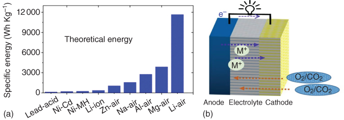
Figure 8.1 (a) Comparison of different batteries in terms of energy density. (b) Schematic illustration of a typical metal–air battery composed of a metal anode and porous cathode.
8.2 Carbon‐Based, Metal‐Free Cathodes for Li–O2 Batteries
Li–O2 batteries with an ultrahigh theoretical energy density of about 3500 Wh kg−1 have become one of the most promising candidates for electric vehicles (EVs) and hybrid electric vehicles (HEVs) [18, 19]. The discharge reaction at the cathode involves reduction of molecular O2 by Li+ to form lithium peroxide with a reversible cell voltage of 2.96 V or to form lithium oxide with a cell voltage of 2.91 V [18, 20]. During the charging process, the above reactions reverse. In spite of the high cell voltage, the low round‐trip efficiency, inferior power density, and poor cyclability associated with Li–O2 batteries have precluded them from practical applications. In order to alleviate the above‐mentioned problems and achieve the full potential of Li–O2 batteries, efficient cathodes with a large surface area to provide sufficient active sites for actively catalyzing both ORR during discharge and OER during charge processes as well as a large pore volume for discharge product deposition are required. In this regard, porous carbon‐based materials with the desired architecture and bifunctional catalytic activities for both for ORR and OER are ideal cathodes for Li–O2 batteries [1].
Carbon nanomaterials, including carbon nanotubes (CNTs) and graphene, have emerged as attractive electrode materials for efficient energy conversion and storage. Owing to their low cost, large surface area, diverse structure, and morphology for efficient oxygen/electrolyte diffusion and electron transport, high ORR/OER activity, and good corrosion resistance, carbon nanomaterials have been demonstrated to be ideal metal‐free cathodes for Li–O2 batteries. Until now, considerable attention has been directed to the development of various carbon materials with different architectures and microstructures for Li–O2 batteries.
8.2.1 Carbon Nanotubes
Owing to the unique one‐dimensional hollow structure with a high aspect ratio, large surface area, and good electrical conductivity, CNTs exhibited high catalytic activities for ORR and OER reactions [1, 21–24]. When utilized as the air cathode in Li–O2 batteries, the hollow core in CNTs, if made open during production or post‐processing, can provide effective space for ion/oxygen diffusion and Li2O2 deposition while the carbon framework facilitates fast electron transport, leading to enhanced electrochemical performance. Furthermore, various strategies have been developed to improve CNT‐based Li–O2 batteries by constructing porous structures [25], applying nonliquid electrolytes [26, 27], creating active sites [28], introducing defects [29], and fluorination treatment [30]. The good flexibility of CNTs and associated three‐dimensional (3D) networks also facilitate the development of free‐standing and even flexible CNT electrodes [31].
Reisner and coworkers [32] reported the first CNT‐based Li–O2 battery, in which both single‐walled and multiwalled CNTs were used as the cathodes and demonstrated to display higher capacities compared with those of carbon black, graphite, and active carbon. Recently, Zhu et al. [33] directly grew CNTs from hydroquinone resin onto a macroporous Ni foam (Figure 8.2a) to produce electrodes with interconnected macroporous channels, large void space, and good contact between CNT and the substrate. This arrangement facilitated the discharge product deposition and the oxygen/Li+ transportation into the entire electrode at different depths of cycling. As a result, a long‐term cycling stability up to 110 cycles at 200 mA g−1 and high rate capability up to 12 690 mAh g−1 at 200 mA g−1 and 3999 mAh g−1 at 2000 mA g−1 were obtained (Figure 8.2b,c).

Figure 8.2 (a) SEM images of CNT/Ni foam electrodes. (b) Discharge/charge profiles of CNT/Ni foam electrode tested at various current density. (c) Cycling performance of CNT/Ni foam electrode tested at 200 mA g−1 with a cut‐off capacity of 2000 mAh g−1.
Source: Zhu et al. 2016 [33]. Copyright 2016. Reprinted with permission from American Chemical Society.
In a similar but separate study, Lim et al. [34] synthesized CNTs with a well‐aligned fibril and hierarchical porous architecture and their performance was demonstrated as the air cathode in Li–O2 batteries by a high cycling life and excellent rate capability. However, Liu et al. [25] prepared hierarchically porous CNTs by vacuum filtration using polystyrene (PS) spheres as templates (Figure 8.3a), which, when used as a binder‐free air electrode in Li–O2 batteries, exhibited a specific capacity of 4683 mAh g−1 with an excellent rate capability. Compared to unmodified CNT films, the hierarchically porous CNT films exhibited a higher capacity and superior rate capability (Figure 8.3b), suggesting the importance of the large open tunnels and nanoporosity for rapid transport of O2 and effective catalysis.

Figure 8.3 (a) Schematic illustration of the fabrication process of hierarchical porous CNTs films. (b) Rate capability of pure CNTs films and hierarchical porous CNTs films at various current densities. (c) Discharge/discharge curves and SEM images of pristine CNTs and defective CNTs, along with the schematic illustration of Li2O2 formation on the surface of the electrodes.
Source: Huang et al. 2014 [29]. Copyright 2014. Reprinted with permission from American Chemical Society.
Source: Liu et al. 2013 [25]. Copyright 2013. Reprinted with permission from Royal Society of Chemistry.
Generally speaking, the introduction of defects into host materials can generate more active sites for electrochemical reactions. Thus, defects were introduced into CNT electrodes by argon plasma treatment [29] and investigated in Li–O2 batteries using tetra(ethylene glycol) dimethyl ether (TEGDME) as the solvent and N‐methyl‐N‐propylpiperidinium bis(trifluoromethanesulfonyl)imide (PP13TFSI) as the electrolyte. An increased discharge capacity and a low cycle overpotential were observed due to the defect‐induced increase in the nucleation sites for Li2O2 growth and a decrease in the size of the resultant Li2O2 particles (Figure 8.3c).
An alternative approach to defect introduction involves the placement of active edge sites on carbon substrates and their use in high‐performance carbon electrodes. In this context, Lai and coworkers [28] partially cracked CNTs with active edge sites and hierarchical pores. Electrodes fabricated from these materials exhibited nearly two times higher discharge capacity compared to that of the pristine CNTs. In view of highly localized Li–O2 reactions induced by high O2 affinity of perfluorinated moieties, Thomas et al. grafted a perfluorinated alkyl chain onto CNTs and tested them as the air cathode in Li–O2 batteries [30], leading to an improved cell capacity. Also, solid‐state and ionic‐liquid electrolytes have been used to modify electrochemical performance of CNT cathodes in Li–O2 batteries [26, 27].
8.2.2 Graphene
Graphene, a two‐dimensional (2D) atomic‐thick graphitic carbon sheet, has attracted a great deal of interest as an efficient electrode material for various energy conversion and storage devices. This is because graphene sheets possess a large specific surface area, excellent electrical conductivity, and good electrochemical stability [35–37]. Moreover, 2D graphene sheets can be assembled into 3D free‐standing aerogels with a wide range of pore sizes and highly conductive network, holding great promise as cathodes in Li–O2 batteries [14, 15, 38–44]. In this context, Yoo and Zhou et al. reported the first graphene‐based, metal‐free cathode for Li–O2 batteries (Figure 8.4a) [45]. In this case, it was proposed that the edges or defects on the graphene sheet might serve as active sites to dissociate O2 into atomic oxygen, followed by reacting with H2O molecules in the aqueous electrolyte to form hydroxide ions. Owing to the excellent conductivity and the presence of sp3 bonding related to the edge and defect sites, the graphene air cathode exhibited a low overpotential of 0.56 V at the initial cycles, despite a very low cycling depth (Figure 8.4b). Moreover, the cell cycling stability was further improved by a heat treatment to decrease the sp3:sp2 ratio and remove functional groups form the graphene surface. Later, Kim et al. [46] prepared a flexible binder‐free graphene paper/graphene oxide (GO) cathode through vacuum‐assisted filtration, which, when applied in Li–O2 batteries, showed a higher discharge capacity in comparison with that of the rGO paper and commercial carbon paper.
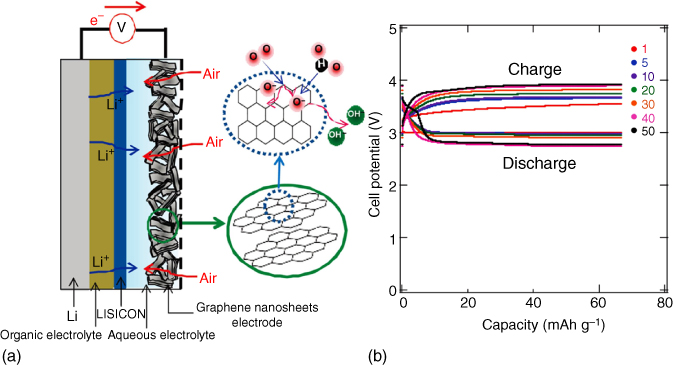
Figure 8.4 (a) The structure of the rechargeable Li–air battery based on graphene as an air cathode. (b) Charge/discharge curves of graphene at 0.5 mA cm−2.
Source: Yoo and Zhou 2011 [45]. Copyright 2011. Reprinted with permission from American Chemical Society.
In another approach, Sun et al. [39] prepared macroporous graphene with different pore sizes using SiO2 spheres as templates to introduce macropores for effective deposition sites of the discharge products. It was found that the porous graphene framework with a pore diameter of 250 nm exhibited the highest discharge capacity among all the prepared samples. Using PS spheres as the template [15], 3D graphene frameworks with open and interconnected porous networks were also prepared, which, when used as the cathode in Li–O2 batteries, exhibited high specific capacities, excellent rate capabilities, and reduced overpotentials.
Lin et al. [47] recently reported ultrahigh areal capacity air cathodes for Li–O2 batteries using holey graphene, a structural derivative of graphene with through‐thickness holes averaging 5–15 nm. The presence of these holes enabled the holey graphene powder to be readily compression molded into disk shape under solvent‐free conditions. These discs were then directly used as ultrathick, binder‐free air cathodes. The high areal mass loading of holey graphene (up to ∼10 mg cm−2) led to extraordinary areal capacitance (as high as 40 mAh cm−2), with gravimetric capacity still comparable to most state‐of‐the‐art carbon‐based air cathodes. These ultrathick air cathodes also exhibited good cyclability, stable over more than 20 cycles at a curtailing capacity as high as 2 mAh cm−2. The compressibility of holey graphene further allowed the fabrication of more complex air cathode architectures with embedded metal catalysts, which also exhibited high areal performance [48].
8.2.3 Porous Carbon Nanomaterials
It has been demonstrated that the capacity of Li–O2 batteries using carbon cathodes is mainly determined by the porosity, including pore volume and pore size, available for the deposition of discharge products [49, 50]. An air cathode with abundant hierarchical pore size and distribution shows improved electrochemical performances [49], as mesopores can effectively improve the electrode–electrolyte interaction and provide more active sites for electrochemical reactions. In addition, macropores reduce the blockage of electrolyte and oxygen pathways and improve O2 diffusion and reversible conversion [9, 51]. Therefore, carbon‐based air cathodes with hierarchical porous architectures have demonstrated performance improvements in Li–O2 batteries.
Several strategies have been developed to construct air electrode with hierarchically porous structures for Li–O2 batteries. A template‐assisted method has been considered as a facile fabrication approach. For instance, Li et al. [52] prepared a micro‐sized honeycomb‐like carbon cathode using CaCO3 as a template. The presence of intrinsic mesopores provided effective sites for Li2O2 deposition while the template‐generated macropores facilitated the transport of oxygen gas. Consequently, a higher electrode space utilization and discharge capacity were demonstrated as compared to those using commercial Ketjen black. More recently, Yin et al. [53] fabricated modified carbon fibers by electrospinning in the presence of silica spheres to introduce interconnected hollow macropores (Figure 8.5a). When used as a binder‐free, free‐standing air cathode, these macropores led to a high specific capacity, good rate capability, and excellent cycling stability. Alternatively, Zhang et al. [54] prepared porous carbon–nitrogen architectures with both mesopores and macrochannels (Figure 8.5b,c) by a sol–gel approach and obtained a high electrochemical activity and stable cyclability over 160 cycles for a Li–O2 battery (Figure 8.5d).
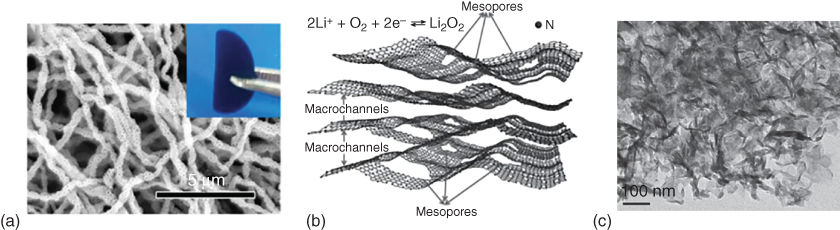
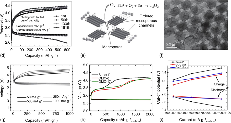
Figure 8.5 (a) SEM image of the porous carbon fibers fabricated by a SiO2 template‐assisted electrospinning method. (b) Schematic illustration and (c) transmission electron microscopy (TEM) image of hierarchical N‐doped carbon with macrochannels and mesoporous pores. (d) Discharge/charge profiles of hierarchical N‐doped carbon with macrochannels and mesoporous pores tested at 200 mA g−1 with a limited capacity of 600 mAh g−1. (e) Schematic illustration of O2/Li2O2 conversion in an ordered hierarchical mesoporous/macroporous carbon catalyst. (f) TEM image of the three‐dimensional ordered mesoporous/macroporous carbon sphere arrays and (g) the related discharge/charge profiles tested at different current densities. (h) Electrochemical performance of Super P electrode, order mesoporous carbon (OMC)‐6 electrode, and OMC‐17 electrode in Li–O2 cells. (i) Cell voltage versus current density with discharge at a limited capacity of 2000 mAh g−1.
Source: Park et al. 2013 [56]. Copyright 2013. Reprinted with permission from American Chemical Society.
Source: Guo et al. 2013 [55]. Copyright 2013. Reprinted with permission from John Wiley & Sons.
Source: Zhang et al. 2014 [54]. Copyright 2014. John Wiley & Sons.
Source: Yin et al. 2016 [53]. Copyright 2016. Reprinted with permission from John Wiley & Sons.
Along with the hierarchical pores, designing ordered structures could facilitate the effective deposition of discharge products and prevent pore clogging during cycling processes. In this regard, Guo et al. [55] introduced ordered mesoporous carbon (OMC)–macroporous carbon (Figure 8.5e,f) as the cathode catalyst in Li–O2 batteries, leading to favorable electrode–electrolyte interaction, fast Li+ diffusion and electron transfer, and large space for O2 diffusion and O2/Li2O2 conversion. As a result, the optimized sample with 30% content of ordered porous carbon arrays displayed an excellent cycling performance with a stable discharge curve of about 2.5 V even when tested at increased current densities (Figure 8.5g), indicating a small polarization and an excellent rate capability.
Ordered, aligned hollow carbon fibers have also been grown on an Al2O3 porous substrate to produce binder‐free electrodes [57], which yielded a high gravimetric energy of up to 2500 Wh kg−1. The presence of an ordered porous structure could not only provide void volume for the Li2O2 deposition but also allow for an effective control of the size of the as‐formed Li2O2 on the carbon electrode. As shown in Figure 8.5h,i, carbon cathodes with ordered mesoporosity of different pore sizes displayed a lower polarization compared with that of the super P. It has also been confirmed that discharged products (Li2O2), confined in the porous channels, with a controlled particle size and crystallinity showed an excellent rate capability [56].
8.2.4 Free‐Standing Carbon Nanomaterials
In conventional Li–O2 batteries, some inactive materials, including current collectors (e.g. Ni foam, Ni mesh, and other metal substrates) and insulating polymer binders, significantly reduce the overall energy density. In order to construct batteries with a high energy density, therefore, one effective strategy is to design free‐standing and binder‐free electrodes. Owing to their excellent electrical and mechanical properties, carbon materials have been demonstrated to be ideal free‐standing, binder‐free, and flexible electrodes that can be used to construct high‐performance Li–O2 batteries, which might find uses for portable and wearable electronic devices.
Of particular interest, Nie et al. [58] fabricated free‐standing activated carbon nanofibers (CNFs) by electrospinning and CO2 activation to allow for feasible permeability of O2 across the micropores between nanofibers of the cathode and to provide the additional nucleation sites for Li2O2 formation within the mesopores generated by CO2 activation. This, together with the elimination of side reactions associated with the polyvinylidene (PVDF) binder, could lead to an increased discharge capacity, reduced overpotential, and better cycle stability compared with the inactivated carbon fibers and conventional BP2000 composite (Figure 8.6a,b). The morphology of the cycled electrode shown in Figure 8.6c shows the activated hierarchical porous carbon fibers.
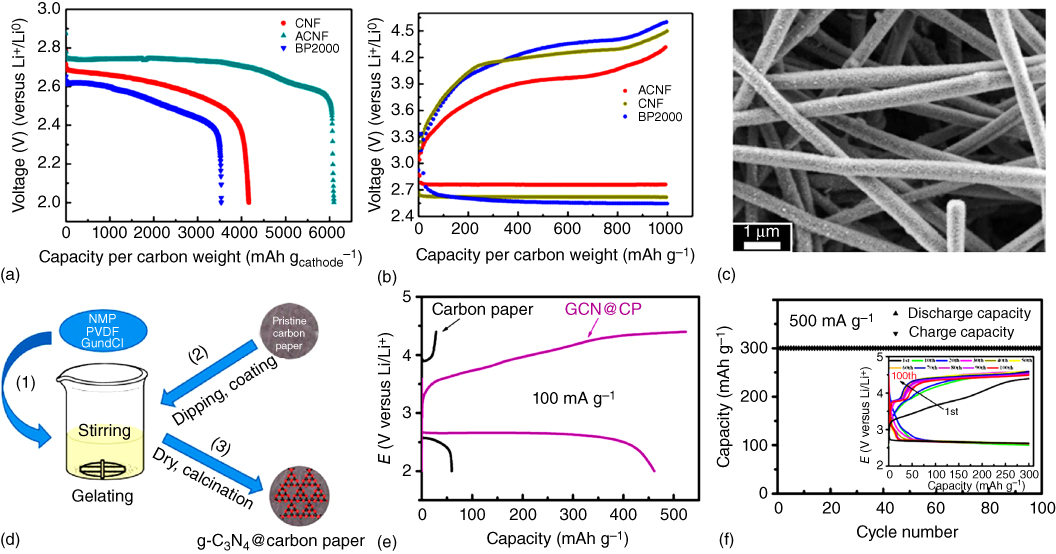
Figure 8.6 (a) Full discharge curves for the first cycle and (b) full discharge/charge profiles of carbon nanofibers (CNFs), activated carbon nanofibers (ACNFs), and BP2000 cathodes at 200 mA g−1 with a limited capacity of 1000 mAh g−1. (c) SEM image of cycled ACNF electrode. (d) Schematic illustration of in situ preparation of graphitic C3N4@carbon paper. (e) Discharge/charge curves of carbon paper and graphitic C3N4@carbon paper at 100 mA g−1. (f) Cycling performance and the corresponding discharge/charge profiles (inset) of graphitic C3N4@carbon paper at 500 mA g−1 with a cut‐off capacity of 300 mAh g−1.
Source: Yi et al. 2015 [59]. Copyright 2015. Reprinted with permission from American Chemical Society.
Source: Nie et al. 2016 [58]. Copyright 2016. Reprinted with permission from American Chemical Society.
Using an in situ fabrication method (Figure 8.6d), graphitic‐C3N4 was combined with carbon paper as an air cathode for Li–O2 batteries [59]. In this particular case, the capacity was calculated to contain a 13% contribution from carbon paper and an 87% contribution from C3N4 (Figure 8.6e). However, the pure C3N4 shows a large overpotential and poor cycling stability due to its limited electron transfer ability. Owing to its high nitrogen content and improved electronic conductivity, the C3N4@carbon paper composite cathode showed a low‐voltage gap, good rate capability, and long cycling life (Figure 8.6f).
8.2.5 Doped Carbon Nanomaterials
Heteroatom doping of graphitic carbon structures has been demonstrated to tune electronic and other physicochemical properties, thereby providing more active sites for catalyzing/interacting with oxygen molecules [1, 20, 60–62]. Earlier theoretical and experimental studies [23, 63–65] have revealed that the relatively high electron affinity of N dopants could endow the adjacent C atoms with positive charges to change the adsorption mode of O2, facilitating the ORR. Thus, heteroatom doping has been widely used to modify carbon‐based cathodes in advanced Li–O2 batteries [66–71].
Owing to the novel multilayer lamellar structure, onion‐like carbon (OLC) exhibits appealing characteristics, including large pore volume, large surface area, and uniform pore size distribution, which are attractive for catalysis. This, together with the N‐doping‐induced ORR activity, prompted Shu et al. [66] to prepare N‐doped onion‐like carbon (N‐OLC) as an advanced oxygen electrode in long‐life Li–O2 batteries. Compared with the pure OLC and commercial super P, a lower overpotential gap and higher round‐trip efficiency were obtained for the N‐OLC electrode (Figure 8.7a). Among these electrodes, the N‐doped onion‐like carbon also displayed the highest discharge capacity and capacity retention even when tested at increased current densities (Figure 8.7b).

Figure 8.7 (a) Initial discharge/charge profiles at 0.15 mA cm−2 and (b) discharge capacity retention at various current densities of N‐doped onion‐like carbon (N‐OLC), OLC, and super P. (c) Discharge/charge curve of the N‐doped vertically aligned coral‐like carbon nanofiber arrays (VA‐NCCF). The inset is related TEM image and the sketch of Li2O2 grown on VA‐NCCF. (d) Discharge/charge profiles of CNT powder, vertically aligned carbon nanotube (VA‐CNT), and VA‐NCCF under same conditions. (e) Schematic illustration of the formation process of N‐doped carbon/carbon black composite and its effect on the growth of Li2O2 as well as discharge capacity.
Source: Lin et al. 2016 [71]. Copyright 2016. Reprinted with permission from Elsevier.
Source: Shui et al. 2014 [67]. Copyright 2014. Reprinted with permission from American Chemical Society.
Source: Shu et al. 2016 [66]. Copyright 2016. Reprinted with permission from Royal Society of Chemistry.
Using N‐doped vertically aligned coral‐like carbon nanofiber (VA‐NCCF) arrays as the air cathode, Shui et al. [67] reported a Li–O2 battery with a high energy efficiency up to 90% and a narrow voltage gap as low as 0.3 V. The N doping coupled with the branched morphology ensured a significant reduced overpotential and a high uptake of the discharge product for the Li–O2 battery compared to its counterpart based on undoped CNT and CNT powder cathode, respectively (Figure 8.7c,d). In general, N‐doped carbon nanomaterials could act as active metal‐free bifunctional catalysts for ORR and OER to enhance the performance of Li–O2 batteries [72]. Compared to doping‐free graphitic carbon cathodes, N‐doped graphitic carbon displayed a much higher capacity, better rate capability, and longer cycle life [68]. Furthermore, N doping was found to also affect the growth of discharge products [71]. Li2O2 was demonstrated to be deposited along the surface of the carbon material by a surface pathway and perpendicular to the surface by a solvent pathway in N‐doped carbon/carbon black composites. The presence of pyridinic‐N enhanced the solvent pathway, resulting in the formation of a nanosheet morphology, which led to a favorable Li+/O2 transport and an increased discharge capacity (Figure 8.7e).
Owing to the high efficiency of g‐C3N4 nanosheets for ORR and OER reactions, g‐C3N4 was attached on the graphene nanosheet (GN) to enhance its conductivity, which then served as a macroporous free‐standing air cathode for Li–O2 batteries [40]. The as‐formed macroporous structure promoted electron transfer and provided a high density of deposition sites for reaction products, leading to a high round‐trip efficiency and favorable rechargeability. The prepared composite electrode displayed a 0.48 V lower charging potential and 0.13 V higher discharging potential than those of the pure graphene, suggesting that the performance enhancement was due to synergistic effects between C3N4 and graphene. Even after 105 cycles at 1000 mAh g−1, excellent cycling stability along with terminal voltage higher than 2.4 V could still be obtained.
To combine the appealing merits of the heteroatom doping with the edge effect discussed above, Dai and coworkers developed holey graphene treated with NH3 atmosphere as a binder‐free air cathode for Li–O2 batteries [14]. As shown in Figure 8.8a–d, the resulting batteries showed a lower overpotential gap and better cycling stability compared to those of the reduced graphene (r‐Gr) and reduced holey graphene (r‐HGr) electrodes.

Figure 8.8 (a, b) Discharge/charge profiles of N‐doped holey graphene (N‐HGr), pristine graphene (r‐Gr), and pristine holey graphene (r‐HGr) at 40 mA g−1. (c, d) Cycling stability of N‐doped holey graphene (N‐HGr), reduced graphene (r‐Gr), and reduced holey graphene (r‐HGr) at 40 mA g−1.
Source: Shui et al. 2016 [14]. Copyright 2016. Reprinted with permission from American Chemical Society.
Chen and coworkers [44] investigated the related effect of chemical doping on the electrochemical performance of nanoporous graphene cathodes in Li–O2 batteries. It was found that N doping led to a large discharge capacity, whereas S doping imparted a stable cycling behavior to graphene electrodes (Figure 8.9a). Zhao et al. [42] synthesized 3D porous N‐doped graphene aerogels as air cathodes in Li–O2 batteries. The well‐developed interconnected channels combined with the full exposure of electrochemical active sites ensured a long cycle stability and good rate capability.
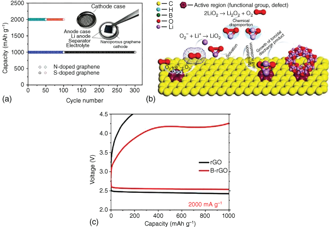
Figure 8.9 (a) Schematic representation of doped nanoporous graphene‐based Li–O2 batteries and cycling stability of N‐doped graphene and S‐doped graphene tested with a cut‐off capacity of 1000 and 2000 mAh g−1. (b) Schematic illustration of the Li2O2 formation on the active region of B‐doped rGO. (c) Comparison of discharge/charge curves of B‐doped rGO and rGO at 2000 mA g−1.
Source: Wu et al. 2016 [73]. Copyright 2016. Reprinted with permission from American Chemical Society.
Source: Han et al. 2016 [44]. Copyright 2016. Reprinted with permission from John Wiley & Sons.
In order to gain a better understanding of the heteroatom‐doping effect on the performance of Li–O2 batteries, density functional theory (DFT)‐based first‐principle calculations were performed to evaluate the effect of B doping on the performance of graphene cathodes [41]. B doping was demonstrated to effectively reduce the barrier for the charge rate‐determining step and increase charge transfer of Li2O2 to the substrate, facilitating the activity of Li–O bonds as well as the oxidization of O22− to O2. Combined theoretical and experimental investigations further demonstrated that B‐doped rGO was a promising cathode in Li–O2 batteries [73]. Boric acid, with cross‐linking and pore‐forming capabilities, has also been used as a B source to be doped into carbon lattices to generate more defects and activate electrons in carbon cathodes, facilitating fast charging at large current densities. Boron–oxygen groups linked to carbon could serve as additional reaction sites to activate the ORR process (Figure 8.9b). DFT calculations confirmed more effective activation of Li–O bonds in decomposing Li2O2 for B‐rGO, as opposed to rGO, most likely due to stronger interactions between B‐rGO and Li5O6 clusters. Consequently, lower overpotentials were exhibited as shown in Figure 8.9c.

Figure 8.10 (a) The correlation between carbon pore size and cell capacity. (b) Discharge curves of carbon nanofoams with different pore size distributions tested at 0.3 mA cm−2. (c) Schematic diagram of an air electrode composed of carbon nanotubes and solid electrolyte particles in Li–air batteries. (d) Discharge curve of the solid‐state CNT cells at various current densities.
Source: Kitaura and Zhou 2012 [26]. Copyright 2012. Reprinted with permission from John Wiley & Sons.
Source: Chervina et al. 2011 [74]. Copyright 2011. Reprinted with permission from Electrochemical Society.
Ding et al. 2014 [50]. Copyright 2014. Reprinted with permission from Royal Society of Chemistry.
8.2.6 Structure–Property Relationship of Carbon Cathodes in Li–O2 Batteries
Based on the study on eight different carbon electrode materials with various pore sizes and pore volumes, Hor and coworkers [50] proposed a correlation between the initial discharge capacity and the cathode structure. Instead of the electrode surface area, pore size and pore volume were demonstrated to play a direct role in determining the initial discharge capacity (Figure 8.10a). Furthermore, the established correlations between the pore distribution and specific capacity of a binder‐free carbon nanofoam with pore sizes ranging from mesopores (5–50 nm) to small macropores (100–200 nm) was used to guide the development of a gradient cathode structure with a distribution in pore size from macropores on the O2 side to mesopores on the flooded, electrolyte‐side (Figure 8.10b) [74].
As carbon materials can be fabricated with varied structures and morphologies, the electrochemical performance of carbon electrodes could be affected by many factors. To explore the structure–property/performance relationships, Li et al. [75] treated carbon black under different atmospheres and found that the specific surface area of carbon mesopores was one of the key factors influencing the battery performance and that the introduction of nitrogen‐ and oxygen‐bearing functionalities had a negligible effect on the related performance. Itkis et al. [76] investigated the reactivity of carbon in Li–O2 batteries and demonstrated that carbon materials with a low content of functional groups, combined with defects, would have better stability for Li–O2 batteries. Zhou et al. [77] thus proposed a crucial “double‐edged sword effect” of oxygen species on the performance of carbon electrodes in Li–O2 batteries; oxygen species could weaken the interface stability between carbon and electrolyte but promote the ORR.
Apart from the pure O2 and liquid electrolyte systems, the electrochemical performance of 3D porous multiwalled CNT paper in solid‐state lithium–air batteries has also investigated (Figure 8.10c) [26]. In this particular case, air was used as an experimental atmosphere throughout the testing process. It was found that large surface areas combined with high aspect ratios of CNTs led to continuous charge pathways and good contact with the solid electrolyte. The presence of a large amount of void space and interpenetrating structure within the CNT paper supported a high uptake of Li2O2 particles. Consequently, the CNT paper exhibited a specific capacity of 420 mAh g−1 at 10 mA g−1. In addition, an improved reversibility was seen from the rate capability testing, as shown in Figure 8.10d.
8.3 Carbon‐Based, Metal‐Free Cathodes for Na–Air Batteries
Na–air batteries are known to have lower theoretical specific energy densities as opposed to other metal–air batteries (1605 Wh kg−1 for the cell with discharge product of Na2O2; 1108 Wh kg−1 for the cell with discharge product of NaO2) [78]. In spite of a relatively low energy density, Na–air batteries have recently attracted considerable attention due to the natural abundance of Na resources and a lower charging overpotential, along with a possibly higher cycling performance and lower cost compared to Li–air batteries [79, 80]. However, similar to other air‐based batteries with cathodes of a low electrical conductivity, excessive discharge products could accumulate on the cathode surface to deactivate reaction sites on the surface and block the diffusion paths for gas [81, 82]. Therefore, it is highly desirable to develop cathodes with appropriate architectures and morphologies to reduce polarization as well as improve cycling performance.
Compared with the normal carbon film electrodes, GN cathodes in Na–air batteries were demonstrated to show a higher discharge capacity of 9268 mAh g−1 with lower overpotential (Figure 8.11a) [83]. Even at a high current density of 1000 mA g−1 (Figure 8.11b), a discharge capacity of about 1000 mAh g−1 could be obtained, indicating a good rate capability for the GN air cathode in Na‐ion batteries. However, the GN cathode exhibited a short cycling life of 10 cycles, although still better than that of a carbon film electrode, due to the low solubility of the reduction products. In addition, the influence of Na salts on the capacity delivery by GNs was also investigated (Figure 8.11c), which confirmed the important role of NaClO4 in enhancing the performance of the graphene‐based Na–air battery.

Figure 8.11 (a) Discharge/charge curves of graphene and normal carbon film at 300 mA g−1. Discharge/charge curves of graphene (b) at various current densities and (c) with different electrolytes. (d) SEM and (e) TEM images of N‐doped CNTs/carbon paper. (f) Discharge/charge profiles of N‐doped CNTs/carbon paper and carbon paper at 0.1 mA cm−2.
Source: Yadegari et al. 2015 [84]. Copyright 2015. Reprinted with permission from American Chemical Society.
Source: Liu et al. 2013 [83]. Copyright 2013. Reprinted with permission from Royal Society of Chemistry.
In order to investigate possible correlations among the discharge capacity, morphology, specific area and porosity, charging overpotential, and discharge reaction rate, a series of designed tests were carried out by Sun and coworkers [85]. In these studies, heat‐treated carbon black was used as the air cathode in Na–air batteries. It was demonstrated that a larger surface area led to an increased specific discharge capacity by increasing the density of accumulation sites for the solid discharge products. Chemical composition of the discharge products, along with the charging overpotential, was found to strongly depend on the discharge reaction rate. In addition, the specific surface area and pore size greatly affected the morphology of the solid discharge product. The same group also investigated the influence of humidity on the surface of CNT air cathodes [86]. Various discharge products, ranging from sodium superoxide and peroxide to hydroxides and carbonates, can be generated with increasing humidity.
In addition to the GN cathodes discussed above, N‐doped CNTs with a high electrochemical conductivity and electrocatalytic activity have also been used as good catalysts for Na–O2 batteries. In particular, an efficient air cathode based on 3D porous N‐doped CNTs vertically grown on a carbon paper was explored as a free‐standing electrode in Na–O2 batteries (Figure 8.11d,e) [84]. The presence of macropores and mesopores in the N‐doped CNTs increased the void volume for O2 and Na+ transport and hosted the solid‐state discharge product efficiently. The micropores in the carbon paper enabled the continuous supply of O2 and Na+ onto the electrode surface. As a result, a specific capacity of 17 times higher than that of the pure carbon paper was obtained (Figure 8.11f). Both sodium superoxide and peroxide were produced and decomposed at different overpotentials. The formation of carbonate‐based parasitic products originated from the reaction between discharge products with the electrolyte during cycling process was demonstrated to cause poor cyclability.
Controlling the porosity and pore size distribution of carbon materials is a creative and effective strategy for developing air cathodes. In this regard, Wang and coworkers fabricated hierarchical porous carbon spheres imbedded with macropores distributed between carbon spheres and nanopores (Figure 8.12a,b) [87]. The proposed structure was beneficial for electrolyte impregnation and oxygen diffusion into the inner part of the air cathode to enable effective formation and decomposition of NaO2 during cycling resulting in a long cycling life (Figure 8.12c). OMC could also be used as a conductive matrix host for discharge products in Na–air batteries [81]. As shown in Figure 8.12d–f, the as‐prepared OMC showed a lower overpotential and better cycling stability than those of the super P at 100 mA g−1. Characterization of the cycled electrode shown in Figure 8.12g verified a well‐maintained porous structure and penetration of discharge products within the OMC pores. Related results indicate that the pore volume plays an important role in reversible capacity while the pore size influences the cycle life and reversibility.

Figure 8.12 (a) Schematic illustration of the formation process of porous carbon spheres and (b) the related TEM image. (c) Cycling performance of the porous carbon spheres in Na–O2 batteries. (d) SEM image of the order mesoporous carbon. (e) Initial discharge/charge profiles of order mesoporous carbon and super P at 100 mA g−1. (f) Cycling performance of ordered mesoporous carbon at 100 mA g−1. (g) The TEM image of the cycled ordered mesoporous carbon electrode and the corresponding field‐emission transmission electron microscope (FE‐TEM) image (inset). The green part represents elemental sodium.
Source: Kwak et al. 2015 [81]. Copyright 2015. Reprinted with permission from Elsevier.
Source: Sun et al. 2017 [87]. Copyright 2017. Reprinted with permission from John Wiley & Sons.
Das et al. [80] investigated the electrochemical performance of the super P as air cathodes for Na–CO2/O2 batteries using the CO2/O2 hybrid gas. Compared with the batteries tested under pure O2 gas, the energy density could be enhanced up to 200–300%, indicating that metal–air batteries may be benefit from CO2‐enriched air. Zhao and Guo [88] used vertically aligned CNTs grown on stainless steel networks as the air cathodes for Na–O2 batteries. Different kinds of electrolytes, including ethylene carbonate/propylene carbonate, PP13TFSI, and TEGDME‐based electrolyte, were used. Among them, TEGDME‐based electrolytes showed the best stability and highest electrical energy efficiency.
Based on the previous reports on the use of carbon cathodes in Li–air or Na–air (including O2 and CO2 gas) batteries, the comparisons of their electrochemical performances were compiled in Table 8.1.
Table 8.1 Summary of carbon material performance in Li/Na–air batteries.
| Materials | Electrolyte | Testing conditions | Overpotentials | References |
| Mesoporous/macroporous graphene | 0.1 M LiClO4 in DMSO | Li–O2 batteries, current density: 1 000 mA g−1 | c. 1.52 V at first cycle, 1.50 V at fifth cycles, with limited capacity of 1000 mAh g−1 | [49] |
| Graphene nanosheets | 1 M LiClO4 in EC/DEC | Li–O2 batteries, current density: 0.5 mA cm−2 | 0.56 V at first cycle, 1.20 V at 50th cycles, with limited capacity of 65 mAh g−1 | [45] |
| Porous graphene | 0.1 M LiClO4 in DMSO | Li–O2 batteries, current density: 200 mA g−1 |
c. 1.42 V at first cycle, 1.60 V at 20th cycles, with limited capacity of 500 mAh g−1 |
[39] |
| 3D porous N‐doped graphene aerogel | 1 M LiTFSI in TEGDME | Li–O2 batteries, current density: 300 mA g−1 | c. 1.37 V at first cycle, 1.60 V at 60th cycles, with limited capacity of 1000 mAh g−1 | [42] |
| Binder‐free graphene paper | 1 M LiNO3 in DMAc | Li–O2 batteries, current density: 200 mA g−1 | c. 1.0 V at first cycle, 2.50 V at 18th cycles, with limited capacity of 1 000 mAh g−1 | [46] |
| Ultrathin graphene sheets | 1 M LiPF6 in TEGDME | Li–O2 batteries, current density: 200 mA g−1 | c. 1.95 V at first cycle, with limited capacity of 3 000 mAh g−1 | [15] |
| Macroporous graphene@gC3N4 | 1 M LiCF3SO3 in TEGDME | Li–O2 batteries, current density: 0.4 mA cm−2 |
c. 1.4 V at first cycle 2.0 V at 105th cycles, with limited capacity of 1 000 mAh g−1 |
[40] |
| N‐doped 3D graphene | 1 M LiCF3SO3 in TEGDME | Li–O2 batteries, current density: 100 mA g−1 | c. 1.6 V at first cycle, 1.9 V at 100th cycles, with limited capacity of 500 mAh g−1 | [43] |
| Doped porous graphene | 1 M LiTFSI in TEGDME | Li–O2 batteries, current density: 300 mA g−1 | N‐doped sample: c. 1.5 V at 1st cycle; 2.0 V at 100th cycles, S‐doped sample: c. 1.8 at first cycle; 2.4 V at 300th cycles, with limited capacity of 1 000 mAh g−1 | [44] |
| N‐doped holey graphene | 1 M LiCF3SO3 in TEGDME | Li–O2 batteries, current density: 40 mA g−1 | c. 0.57 V at first cycle; 1.15 V at 60th cycles, with limited capacity of 800 mAh g−1 | [14] |
| Hierarchical fibril CNTs | 1 M LiPF6 in TEGDME | Li–O2 batteries, current density: 1 000 mA g−1 | c. 1.15 V at 10th cycle; 1.64 V at 60th cycles, with limited capacity of 1 000 mAh g−1 | [34] |
| Multiwalled CNT paper | 1 M LiTFSA in TEGDME | Li–O2 batteries, current density: 500 mA g−1 | c. 1.58 V at first cycle; 1.9 V at 50th cycles, with limited capacity of 1 000 mAh g−1 | [89] |
| Porous CNT film | 1 M LiPF6 in TEGDME | Li–O2 batteries, current density: 500 mA g−1 | c. 1.25 V at first cycle; 1.7 V at 30th cycles, with limited capacity of 500 mAh g−1 | [25] |
| Hierarchical macrochannel/mesoporous N‐doped carbon | 1 M LiTFSI in TEGDME | Li–O2 batteries, current density: 200 mA g−1 | c. 1.4 V at first cycle; 2 V at 161th cycles, with limited capacity of 600 mAh g−1 | [54] |
| Ordered mesoporous carbon | 1 M LiCF3SO3 in TEGDME | Li–O2 batteries, current density: 200 mA g−1 | c. 1.5 at first cycle; 1.5 V at 25th cycles, with limited capacity of 2 000 mAh g−1 | [56] |
| Ordered mesoporous/macroporous carbon | 1 M LiTFSI in TEGDME | Li–O2 batteries, current density: 250 mA g−1 | c. 1.5 at first cycle; 2.1 V at 30th cycles, with limited capacity of 1 000 mAh g−1 | [55] |
| N‐doped graphitic carbon | 1 M LiTFSI in TEGDME | Li–O2 batteries, current density: 100 mA g−1 | c. 1.32 at first cycle; 1.87 V at 38th cycles, with limited capacity of 500 mAh g−1 | [70] |
| Graphitic C3N4@carbon paper | 0.5 M LiClO4 in DMSO | Li–O2 batteries, current density: 500 mA g−1 | c. 1.17 at first cycle; 1.7 V at 100th cycles, with limited capacity of 300 mAh g−1 | [59] |
| N‐doped Ketjen black | 1 M LiNO3 in DMAc | Li–O2 batteries, current density: 100 mA g−1 | c. 0.65 V at first cycle; 0.75 V at 80th cycles, with limited capacity of 500 mAh g−1 | [71] |
| N‐doped porous graphitic carbon | 1 M LiCF3SO3 in TEGDME | Li–O2 batteries, current density: 100 mA g−1 | c. 0.96 V at first cycle; 1.0 V at 20th cycles, with limited capacity of 500 mAh g−1 | [70] |
| Super P | PMMA/PSt/SiO2/PP‐based gel polymer electrolyte | Li–CO2 batteries, current density: 200 mA g−1 | c. 1.55 V at first cycle; 1.6 V at 50th cycles, with limited capacity of 1 000 mAh g−1 | [90] |
| B,N‐doped holey graphene | 1 M LiTFSI in TEGDME | Li–CO2 batteries, current density: 1 000 mA g−1 | c. 1.68 V at third cycle; 2.15 V at 50th cycles, with limited capacity of 1 000 mAh g−1 | [16] |
| Hierarchical porous carbon sphere | 0.5 M NaCF3SO3 in PC | Na–O2 batteries, current density: 1 000 mA g−1 | c. 0.55 V at first cycle; 1.63 V at 150th cycles with limited capacity of 1 000 mAh g−1 | [87] |
| Ordered mesoporous carbon | 0.5 M NaCF3SO3 in PC | Na–O2 batteries, current density: 100 mA g−1 | c. 1.35 V at first cycle; 1.33 V at 20th cycles with limited capacity of 500 mAh g−1 | [81] |
| Graphene nanosheet | 0.25 M NaPF6 in DME | Na–O2 batteries, current density: 300 mA g−1 | c. 1.35 V at first cycle; 1.8 V at 10th cycles, with limited capacity of 1 200 mAh g−1 | [83] |
| N‐doped CNTs on carbon paper | 0.5 M NaCF3SO3 in DEGDME | Na–O2/CO2 batteries, current density: 0.1 mA cm−2 | c. 1 V at first cycle; 2.2 V at 15th cycles, with limited capacity of 0.5 mAh cm−2 | [84] |
| SCNTs | 1 M NaClO4 in TEGDME | Na–CO2 batteries, 1 000 mA g−1 | c. 1.5 V at first cycle; 1.8 V at 20th cycles, with limited capacity of 2 000 mAh g−1 | [91] |
All the voltages were calculated based on the half of the limited capacity. (DEC: diethyl carbonate, DMSO: dimethyl sulfoxide, LiTFSI: lithium bis(trifluoromethanesulfonyl)imide, TEGDME: tetra(ethylene glycol)dimethyl ether, DMAc: N,N‐dimethylacetamide, PMMA: polymethyl methacrylate, PSt: polyphenylmethylsiloxane, PP: polypropylene, PC: polycarbonate, DEGDME: diethylene glycol dimethyl ether, LiTFSA: lithium bis(trifluoromethanesulfonyl)amide, PEG: poly(ethylene glycol), EC/DEC: ethylene carbonate/diethyl carbonate, DME: 1,1‐dimethoxyethane, SCNT: multi‐wall carbon nanotube.
8.4 Carbon‐Based, Metal‐Free Cathodes for Zn–Air Batteries
The low‐cost, high theoretical energy density (1086 Wh kg−1), and environmental friendliness have made Zn–air batteries attractive for energy conversion and storage [92–95]. However, the development of rechargeable Zn–air batteries has been impeded by their low power output capability due to the lack of efficient air catalysts and limited cyclability of Zn anodes. A Zn–air battery is composed of a Zn anode, a membrane separator, and an air cathode assembled together in an alkaline electrolyte. During the discharge process, Zn reacts with electrolytes, forming an intermedium product of Zn(OH)42− and a final product of ZnO by reacting with O2, diffused from the atmosphere, on the surface of the cathode electrocatalyst [95, 96]. A reverse OER reaction occurs during charging. Thus, ORR and OER are the key reactions for Zn–air batteries, and one of the main challenges for advancing the Zn–air batteries is to develop highly stable and efficient bifunctional catalysts to increase the oxygen reduction and evolution efficiency. Being highly electrocatalytically active, corrosion resistant, low cost, and abundant, carbon nanomaterials are also ideal electrocatalysts for Zn–air batteries [97].
Using aligned CNT sheets as the air cathode with a spring geometry, Xu et al. fabricated a flexible fiber‐shaped Zn–air battery [97], in which porous carbon sheets with aligned CNTs served as the catalyst layer as well as the current collector and gas diffusion layer. Solid‐state hydrogel polymer electrolyte (composed of 8.3 wt% poly(vinyl alcohol), 0.83 wt% poly(ethylene oxide) (PEO), and 8.3 wt% KOH)) was used to prevent short‐circuit occurrence and electrolyte leakage, leading to the discharge/charge processes at 1 V and 1 A g−1 with a superb rate capability (Figure 8.13a–c). The resultant flexible fiber‐shaped Zn–air battery could be used to power portable and wearable electronic devices. In another approach, Park et al. prepared porous N‐doped carbon fibers with a churros morphology by electrospinning [100], which, when assembled into a Zn–air cell, exhibited a high peak density of 194 mW cm−2 comparable to that of its counterpart based on commercial Pt/C catalysts (192 mW cm−2).


Figure 8.13 (a) Rate discharge curves of the fiber‐shaped Zn–air batteries with cross‐stacking angles between 0 °C and 90 °C at various current densities. The layer number was 30. (b) Rate discharge curves of the fiber‐shaped Zn–air batteries with different layer numbers at various current densities. The cross‐stacking angle was 90 °C. (c) Discharge/charge curves of the fiber‐shaped Zn–air batteries at 1 A g−1. (d) TEM image of N‐doped hollow mesoporous carbon. (e) Cycling performance of the N‐doped mesoporous hollow carbon‐based Zn–air batteries at 2 mA cm−2. (f) ORR polarization plots of carbon nanotube fibers, N‐doped carbon nanofibers, and Pt/C catalyst. (g,h) Galvanostatic discharge curves of Zn–air batteries with N‐doped carbon nanofibers and Pt/C as the cathode catalysts at different current densities.
Source: Liang et al. 2015 [99]. Copyright 2015. Reprinted with permission from Elsevier.
Source: Hadidi et al. 2015 [98]. Copyright 2015. Reprinted with permission from Royal Society of Chemistry.
Source: Xu et al. 2015 [97]. Copyright 2015. Reprinted with permission from John Wiley & Sons.
Through a SiO2 template‐assisted synthesis (vide infra), Hadidi et al. prepared N‐doped hollow mesoporous carbon with a large surface area (Figure 8.13d) [98], which, when assembled as a cathode into a Zn–O2 battery with a Zn anode, acted as a bifunctional catalyst and exhibited a superior performance during repeated charge–discharge cycles (Figure 8.13e) compared to the Pt/C catalyst. Likewise, N‐doped macro/mesoporous carbon was prepared as the ORR catalyst with Co3O4@Ni as the OER catalyst in Zn–air batteries [101], leading to exceptional cycling (more than 800 h) and cell efficiency with no significant increase in round‐trip overpotential.
N‐doped carbon nanofiber aerogel derived from bacterial cellulose has also been used as an oxygen reduction electrocatalyst in Zn–air batteries to display a half‐wave potential of 0.8 V and an electron transfer number of 3.97 at 0.8 V as well as electrochemical stability reaching up to 10 000 cycles [99]. Consequently, high voltages of 1.34 and 1.25 V at 1.0 and 10 mA cm−2, respectively, could be obtained, which is superior compared to the commercial Pt/C catalyst (Figure 8.13f–h). Furthermore, Yu and coworkers prepared N‐doped hierarchically porous carbon networks composed of carbon nanosheets [102], which, when used as the air cathode in Zn–air batteries, displayed an efficient electrocatalytic activity for ORR with a high discharge power energy density (up to 80 mW cm−2) and stability over continuous cycles.
To identify active sites for ORR and OER in bifunctional carbon catalysts, a 3D graphene nanoribbon network doped with N was investigated [72] and found that quaternary‐N could provide n‐type doping to catalyze ORR while pyridinic‐N with p‐type doping served as an active site for OER (Figure 8.14a). Consequently, a Zn–air battery with a specific capacity of 873 mAh g−1 was constructed with the N‐doped 3D graphene nanoribbon (Figure 8.14b) and used for O2 and H2 generation (Figure 8.14c), revealing great potential for practical applications.
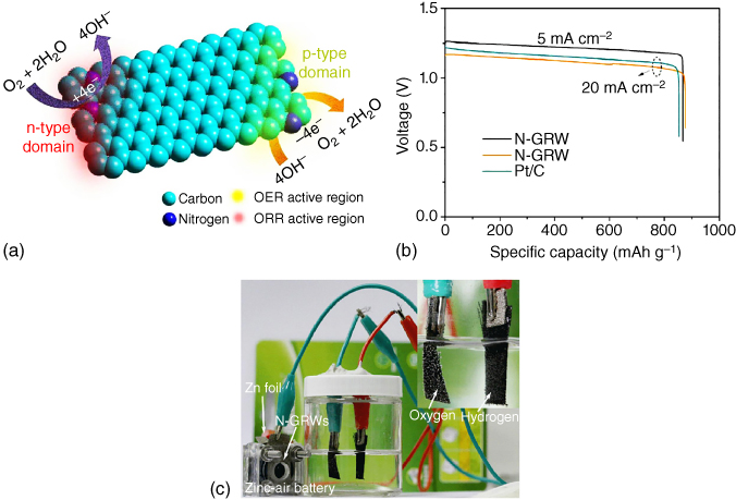
Figure 8.14 (a) Schematic diagram of different active sites on n‐ and p‐type domains for ORR and OER in N‐doped 3D graphene nanoribbons. (b) Discharge/charge profiles and power density of Zn–air battery assembled from N‐doped graphene nanoribbons and Pt/C. (c) Application of Zn–air battery assembled from N‐doped graphene nanoribbons in powering an electrolysis cell.
Source: Reprinted with permission from ref. [72]. Copyright 2016. Science.
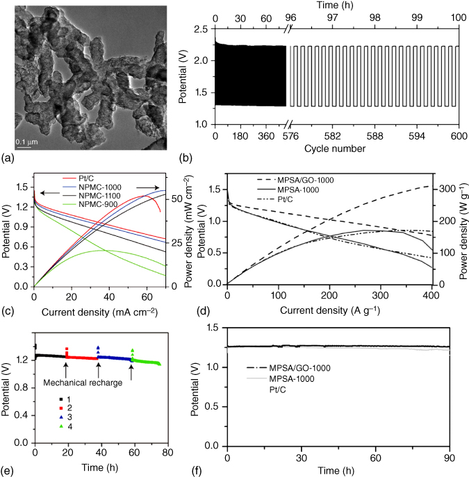
Figure 8.15 (a) TEM image of N,P‐co‐doped carbon foam. (b) Polarization curves and power density of N,P‐co‐doped carbon annealed under different calcining temperature as well as Pt/C in a primary Zn–air batteries. Long‐term cycling of (c) the primary Zn–air batteries and (d) the three‐electrolyte rechargeable Zn–air batteries using N,P‐co‐doped carbon annealed at 1000 °C at 2 mA cm−2. The primary battery is mechanically rechargeable. (e) Polarization curves and power density as well as (f) discharge curves of 3D N,P‐co‐doped carbon networks.
Source: Zhang et al. 2016 [104]. Copyright 2016. Reprinted with permission from John Wiley & Sons.
Source: Zhang et al. 2015 [103]. Copyright 2015. Reprinted with permission from Nature Publishing Group.
Compared to the N‐doped carbon bifunctional ORR and OER catalysts, co‐doping of carbon nanomaterials could provide more efficient modulation of the electronic properties and surface polarities to further increase the ORR and OER activities. In this context, Dai's group developed two different kinds of bifunctional carbon catalysts as the air cathodes for highly efficient Zn–air batteries. As shown in Figure 8.15a–c, the as‐prepared N,P‐co‐doped carbon foam with graphitic edges delivered an energy density of 835 Wh kg−1 and a peak power density of 55 mW cm−2 with a mechanical recharge up to 240 h in the primary Zn–air battery [103]. Even at 2 mA cm−2 (Figure 8.15d), good stability was achieved up to 600 cycles, which was comparable to that of Pt/C. Theoretical calculations confirmed that the presence of N,P‐co‐doping and graphitic edges significantly enhanced the battery performance. Another 3D N,P‐co‐doped porous carbon network was prepared to show synergistic effects with a fast transport of electrons and electrolytes [104], an optimal activity for hydrogen evolution reaction (HER) within a wide pH range, and an excellent ORR activity. As shown in Figure 8.15e,f, the N,P‐co‐doped porous carbon (melamine–phytic acid super‐molecular aggregate (MPSA)/GO‐1000) exhibited a higher potential and power density and a better rate capability compared to Pt/C over the current density range of 100–400 A g−1. Furthermore, an excellent cyclability of up to 90 h was obtained, attractive for developing Zn–air batteries of practical significance.
Like the N,P‐co‐doped bifunctional catalysts discussed above, N,S‐co‐doped carbon was also explored in Zn–air batteries. Lee and coworkers [105] fabricated N,S‐co‐doped C3N4 sponge sandwiched between carbon nanocrystals, which exhibited superior ORR and OER catalytic activities to those of the state‐of‐the‐art RuO2 for OER and Pt/C for ORR. As a result, a primary Zn–air battery based on the N,S‐co‐doped C3N4/carbon nanocrystal cathode displayed a high peak power density of 198 mW cm−2, a maximum current density of 234 mA cm−2 (Figure 8.16a), and cyclability of 210 h after mechanical recharging. More importantly, a low voltage polarization of 0.8 V was obtained at a discharge current density of 25 mA cm−2 in the battery with a three‐electrode system (Figure 8.16b).

Figure 8.16 (a) Polarization plots and power density of the primary Zn–air battery with various catalysts. (b) Polarization plots of S,P‐co‐doped carbon, P‐doped carbon, S‐doped carbon, and Pt/C as air cathodes in a three‐electrode system. (c) Rotating disk electrode voltammograms of N,S‐co‐doped carbon sheet and Pt/C at a rotation rate of 1600 rpm. (d) Polarization plots and power density plot of the Zn–air battery using the N,S‐co‐doped carbon sheet as the cathode catalyst. (e) Schematic illustration of the all‐solid‐state rechargeable Zn–air battery. (f) Discharge/charge profiles of all‐solid‐state rechargeable Zn–air battery at 2 mA cm−2 using N‐doped carbon nanofibers as the catalyst.
Source: Chen et al. 2015 [107]. Copyright 2016. Reprinted with permission from Elsevier.
Source: Su et al. 2016 [106]. Copyright 2016. Reprinted with permission from John Wiley & Sons.
Source: Shinde et al. 2017 [105]. Copyright 2017. Reprinted with permission from American Chemical Society.
N,S‐co‐doped carbon nanosheets derived from a S‐rich polymer precursor have also been demonstrated to be an optimal air cathode with a high electrocatalytic activity for ORR in Zn–air batteries [106], which exhibited a high diffusion current density of −5.1 mA cm−2 and a low half‐wave potential of 0.75 V for ORR (Figure 8.16c). Zn–air batteries based on the N,S‐co‐doped carbon nanosheet cathode showed a current density of 2.1 mA cm−2 at 0.35 V with a peak power density of 0.69 mW cm−2 as well as a good cycling stability of up to 12 h (Figure 8.16d). Qiao and coworkers [107] prepared N,S‐co‐doped graphene microwires as the air cathode in Zn–air batteries that showed a low overpotential of 0.31 V at 10 mA cm−2 and a high faradic efficiency of 95% for OER. Zn–air batteries based on the N,S‐co‐doped graphene microwire cathode discharged smoothly under various current densities and exhibited a peak power density of 5.9 mW cm−2 at 1.1 V.
In order to meet the demand for flexible high‐energy storage, significant effort has been made to develop various flexible power sources. In this regard, Liu et al. [17] prepared a nanoporous carbon nanofiber film as the air cathode in both a liquid Zn–air battery and a flexible all‐solid‐state rechargeable Zn–air battery. The liquid Zn–air battery showed a maximum power density of 185 mW cm−2, an energy density of 776 Wh kg−1, a small voltage gap of 0.73 V at 10 mA cm−2, and an excellent stability up to 500 cycles (Figure 8.16e). Even for the flexible all‐solid‐state device (Figure 8.16f), a low overpotential (0.78 V at 2 mA cm−2), and a long cycle life (6 h) were achieved under repeated bending conditions, indicating excellent cycling performance with a high mechanical stability.
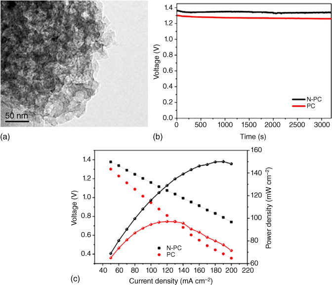
Figure 8.17 (a) Discharge voltage of the N‐doped porous carbon and porous carbon loaded air cathode in Al–air batteries. (b) Discharge voltages and power densities of N‐doped porous carbon and (c) porous carbon in Al–air batteries.
Source: Wang et al. 2015 [108]. Copyright 2015. Reprinted with permission from Elsevier.
8.5 Carbon‐Based, Metal‐Free Cathodes for Other Metal–Air Batteries
Apart from the above‐mentioned highly investigated Li/Na/Zn–air batteries, other metal–air batteries, such as Al–air, Mg–air, and Fe–air batteries‐based on carbon materials, have also been explored as energy storage devices. For instance, Wang et al. [108] investigated the electrochemical performance of N‐doped porous carbon derived from tapioca as the air cathode in Al–air batteries, which exhibited an enhanced electrocatalytic activity with a relatively high discharge voltage of 1.36 V at 50 mA cm−2 in alkaline solutions compared to the undoped porous carbon (Figure 8.17a). Furthermore, a steady decrease in the discharge voltage and increase in the power density was observed with increasing current density (Figure 8.17b,c), indicating an optimal performance for the Al–air batteries (Table 8.2).
Table 8.2 Summary of carbon materials performance in Zn–air and Al–air batteries.
| Materials | Electrolyte | Battery performance | References |
| N‐doped carbon nanofibers | 6 M KOH |
Zn–air battery: A high voltage of 1.25 V and gravimetric energy density of 760 Wh kg−1 were obtained at a current density of 10 mA cm−2 |
[99] |
| N‐doped porous carbon fibers | 6 M KOH |
Zn–air battery: Showing a peak power density of 194 mW cm−2 |
[100] |
| N‐doped hollow mesoporous carbon | 6 M KOH |
Zn–air battery: Charge/discharge voltage gaps of 0.85 and 0.89 V were exhibited in the first cycle and after 30 cycles, at current density of 2 mA cm−2 |
[98] |
| Cross‐stacked carbon nanotubes sheets | Unknown |
Zn–air battery: The energy and power densities are 6 Ah l−1 and 5.7 Wh l−1, respectively. At current density of 1 A g−1 at 1.0 V, the stability can be remained up to 30 cycles |
[97] |
| N‐doped graphene | 6 M KOH with 0.2 M ZnCl2 |
Zn–air batteries: The open‐circuit voltage is 1.46 V with a specific capacity of 873 mAh g−1 and peak power density of 65 mW cm−2 |
[72] |
| N,P‐doped carbon network | 6 M KOH |
Zn–air batteries: The peak power density is 310 W g−1 |
[103] |
| N,S‐doped porous nanosheet | 6 M KOH |
Zn–air batteries: The open‐circuit voltage is 0.75 V. The current density is 2.1 mA cm−2 at 0.35 V, corresponding a peak power density of 0.69 mW cm−2 |
[106] |
| 3D N,S‐doped C3N4 sponge | 6 M KOH containing 0.2 M zinc acetate |
Zn–air batteries: The open‐circuit voltage is 1.51 V with a discharge peak power density of 198 mW cm−2, a specific capacity 830 mAh g−1 |
[105] |
| N,S‐doped graphene nanowires | 3 M KOH + 0.2 M Zn(Ac)2 |
Zn–air batteries: The open‐circuit voltage is 1.34 V, the peak power density is 5.9 mW cm−2 at 1.1 V |
[107] |
| Nanoporous carbon fiber films |
6 M KOH containing 0.2 M zinc acetate for the liquid battery; 0.1 g ml−1 of polyvinyl alcohol (PVA) and 0.1 M KOH containing 0.02 M zinc acetate |
Zn–air battery: In a liquid battery, it shows an open‐circuit voltage of 1.48 V, a maximum power density of 185 mW cm−2 and an energy density of 776 Wh kg−1, as well as a charge/discharge voltage gap of 0.73 V at 10 mA cm−2 In a flexible solid‐state battery, it displays a high discharge and charge voltage of 1.0 and 1.78 V at 2 mA cm−2, respectively, as well as a cycling stability up to 6 h |
[17] |
| N‐doped CNTs | 6 M KOH |
Zn–air batteries: Current density of 78.6 mA cm−2 was obtained at 0.8 V with a peak power density of 69.5 mW cm−2 |
[109] |
| N‐doped graphene | 7 M KOH |
Zn–air batteries: The maximum power density is 218 mW cm−2 |
[110] |
| Porous carbon sheets | 6 M KOH with 0.2 M ZnCl2 |
Zn–air batteries: At 5 mA cm−2, it gives a discharge voltage of 1.23 V. The specific capacity of 669 mAh g−1 and a voltage gap of 0.85 V was obtained after 160 cycles |
[111] |
| N‐doped porous carbon | 6 M KOH contained 0.01 M Na2SnO3 and 0.50 mM In(OH)3 |
Al–air battery: a high discharge voltage of 1.36 V can be displayed at 50 mA cm−2 |
[108] |
8.6 Conclusions and Perspectives
Metal–air batteries show great potential to meet the ever‐growing energy demand for EVs and smart power grids. Low‐cost, high‐performance catalysts are a key for the development of advanced metal–air batteries to realize the potential. Owing to their low cost, large surface area, diverse structure, and morphology for efficient oxygen/electrolyte diffusion and electron transport, high bifunctional catalytic activities, and good corrosion resistance, carbon nanomaterials have been demonstrated to be ideal metal‐free cathodes for metal–air batteries. Thus, a broad array of approaches to modify the architecture and catalytic behavior of carbon‐based materials has been made to demonstrate the viability of carbon materials as metal‐free catalysts in metal–air batteries. In this chapter, a timely review on the recent developments of various metal–air batteries, including Li–air, Na–air, Zn–air, Al–air, Mg–air, and Fe–air batteries, with carbon‐based, metal‐free air cathodes is presented. In spite of the significant progress already achieved, challenges still remain in developing a practical metal–air battery with performance exceeding existing LIBs. Critical factors for practical application of highly efficient metal‐free carbon cathodes for high‐performance metal–air batteries require a complex balance of chemical and architectural features including: (i) carbon structures with hierarchical pores, ranging from mesopores and macropores, for efficient electron/electrolyte/gas transport and controlled discharge product deposition; (ii) the cycling life and efficiency of metal–air batteries need to be further improved using appropriate additives in liquid electrolyte or nonliquid electrolyte to prevent unwanted side reactions or electrolyte decomposition, conductivity, and transport properties as well as the electrocatalytic activities of the carbon cathode, for example, by heteroatom doping; (iii) the cycling stability, micro/macrostructures, and defects of carbon materials need to be controllably tuned for efficient charge and mass transport as well as controllable decomposition of discharged products at some active sites; and (iv) protection strategies for metal anodes need to be developed to prevent corrosion by electrolytes that lead to the degradation of efficiency and a shortened battery life; (v) exploring a stable electrolyte is equally critical. In order to improve cycling life and efficiency of metal–air batteries, the availability of electrolytes should be considered. Until now, limited study relating to liquid electrolytes has been reported. Problems associated with evaporation and decomposition of cycling should be resolved using appropriate additives or nonliquid electrolyte. Related mechanisms should likewise be investigated in detail. In regard to the solid or gel‐like electrolyte, the conductivity and transport properties should be improved efficiently.
To address these challenges, various strategies for materials/device design and controlled fabrication have been developed. With the strategies already reported and those under development, advanced metal–air batteries based on metal‐free carbon cathodes of practical significance will likely become practical in the near future. Continued research and development efforts in this emerging field will eventually translate the metal–air technologies to commercial reality.
Acknowledgments
The authors thank our colleagues for their contributions to the work cited. We are also grateful for financial support from NSF (CMMI‐1400274), DOD‐AFOSR‐MURI (FA9550‐12‐1‐0037), NASA (NNX16AD48A), Key Program of National Natural Science Foundation of China (51732002), The National Key Research and Development Program of China (2017YFA0206500), Distinguished Scientist Program at BUCT (buctylkxj02), National Basic Research Program of China (2011CB013000), China Postdoctoral Science Foundation (2017M610036), and the Fundamental Research Funds for the Central Universities (ZY1725).
References
- 1 Dai, L. (2015). Metal‐free catalysts for oxygen reduction reaction. Chem. Rev. 115: 4823–4892.
- 2 Hu, C. and Dai, L. (2016). Carbon‐based metal‐free catalysts for electrocatalysis beyond the ORR. Angew. Chem. Int. Ed. 55: 11736–11758.
- 3 (a) Scrosati, B., Hassoun, J., and Sun, Y.‐K. (2011). Lithium‐ion batteries. A look into the future. Energy Environ. Sci. 4: 3287–3295.(b) Xiao, Y., Sun, P.P., and Cao, M.H. (2014). Core–shell bimetallic carbide nanoparticles confined in a three‐dimensional N‐doped carbon conductive network for efficient lithium storage. ACS Nano 8: 7846–7857.
- 4 (a) Chen, F.Y. and Chen, J. (2012). Metal–air batteries: from oxygen reduction electrochemistry to cathode catalysts. Chem. Soc. Rev. 41: 2172–2192.(b) Xiao, Y., Lee, S.‐H., and Sun, Y.‐K. (2017). The application of metal sulfides in sodium ion batteries. Adv. Energy Mater. 7: 1601329.
- 5 Lu, J., Lee, Y.J., Luo, X. et al. (2016). A lithium–oxygen battery based on lithium superoxide. Nature 529: 377–382.
- 6 Wang, H.‐Q., Hu, S.J., Fan, X.‐P. et al. (2017). CNTs/CFP supported MnO2 cathode catalyst for Li–air batteries. ChemElecChem 4: 2997–3003.
- 7 Shao, Y.Y., Ding, F., Xiao, J. et al. (2013). Making Li–air batteries rechargeable: material challenges. Adv. Funct. Mater. 23: 987–1004.
- 8 Kwak, W.J., Lau, K.C., Shin, C.‐D. et al. (2015). A Mo2C/carbon nanotube composite cathode for lithium–oxygen batteries with high energy efficiency and long cycle life. ACS Nano 9: 4129–4137.
- 9 Cao, R.G., Lee, J.‐S., Liu, M.L., and Cho, J. (2012). Recent progress in non‐precious catalysts for metal–air batteries. Adv. Energy Mater. 2: 816–829.
- 10 Dai, L. (2017). Carbon‐based catalysts for metal‐free electrocatalysis. Curr. Opin. Electrochem. 4: 18–25.
- 11 Lu, J., Lei, Y., Lau, K.C. et al. (2013). A nanostructured cathode architecture for low charge overpotential in lithium‐oxygen batteries. Nat. Commun. 4: 2383.
- 12 Yin, J., Li, Y.X., Lv, F. et al. (2017). NiO/CoN porous nanowires as efficient bifunctional catalysts for Zn–air batteries. ACS Nano 11: 2275–2283.
- 13 Girishkumar, G., McCloskey, B., Luntz, A.C. et al. (2010). Lithium−air battery: promise and challenges. J. Phys. Chem. Lett. 1: 2193–2203.
- 14 Shui, J., Lin, Y., Connell, J. et al. (2016). Nitrogen‐doped holey graphene for high‐performance rechargeable Li‐O2 batteries. ACS Energy Lett. 1: 260–265.
- 15 Yu, C., Zhao, C.T., Liu, S.H. et al. (2015). Polystyrene sphere‐mediated ultrathin graphene sheet‐assembled frameworks for high‐power density Li–O2 batteries. Chem. Commun. 51: 13233–13236.
- 16 Qie, L., Lin, Y., Connell, J. et al. (2017). Highly rechargeable lithium‐CO2 batteries with a boron‐and nitrogen‐codoped holey‐graphene cathode. Angew. Chem. Int. Ed. 56: 6970–6974.
- 17 Liu, Q., Wang, Y., Dai, L., and Yao, J. (2016). Scalable fabrication of nanoporous carbon fiber films as bifunctional catalytic electrodes for flexible Zn–air batteries. Adv. Mater. 28: 3000–3006.
- 18 Li, F.J., Zhang, T., and Zhou, H.S. (2013). Challenges of non‐aqueous Li–O2 batteries: electrolytes, catalysts, and anodes. Energy Environ. Sci. 6: 1125–1141.
- 19 Imanishi, N. and Yamamoto, O.O. (2014). Rechargeable lithium–air batteries: characteristics and prospects. Mater. Today 17: 24–30.
- 20 Kwak, W.‐J., Jung, H.‐G., Aurbach, D., and Sun, Y.‐K. (2017). Optimized bicompartment two solution cells for effective and stable operation of Li–O2 batteries. Adv. Energy. Mater. 7: 1701232.
- 21 Li, J.‐S., Li, S.‐L., Tang, Y.‐J. et al. (2015). Nitrogen‐doped Fe/Fe3C@ graphitic layer/carbon nanotube hybrids derived from MOFs: efficient bifunctional electrocatalysts for ORR and OER. Chem. Commun. 51: 2710–2713.
- 22 Jian, Z.L., Liu, P., Li, F.J. et al. (2014). Core–shell‐structured CNT@ RuO2 composite as a high‐performance cathode catalyst for rechargeable Li–O2 batteries. Angew. Chem. Int. Ed. 53: 442–446.
- 23 Gong, K., Du, F., Xia, Z. et al. (2009). Nitrogen‐doped carbon nanotube arrays with high electrocatalytic activity for oxygen reduction. Science 323: 760–764.
- 24 Liu, X. and Dai, L. (2016). Carbon‐based metal‐free catalysts. Nat. Rev. Mater. 1: 16064.
- 25 Liu, S.H., Wang, Z.Y., Yu, C. et al. (2013). Free‐standing, hierarchically porous carbon nanotube film as a binder‐free electrode for high‐energy Li–O2 batteries. J. Mater. Chem. A 1: 12033–12037.
- 26 Kitaura, H. and Zhou, H.S. (2012). Electrochemical performance of solid‐state lithium–air batteries using carbon nanotube catalyst in the air electrode. Adv. Energy Mater. 2: 889–894.
- 27 Cui, Z.H., Fan, W.G., and Guo, X.X. (2013). Lithium–oxygen cells with ionic‐liquid‐based electrolytes and vertically aligned carbon nanotube cathodes. J. Power Sources 235: 251–255.
- 28 Li, J., Peng, B., Zhou, G. et al. (2013). Partially cracked carbon nanotubes as cathode materials for lithium‐air batteries. ECS Electrochem. Lett. 2: A25–A27.
- 29 Huang, S.T., Fan, W.G., Guo, X.X. et al. (2014). Positive role of surface defects on carbon nanotube cathodes in overpotential and capacity retention of rechargeable lithium–oxygen batteries. ACS Appl. Mater. Interfaces 6: 21567–21575.
- 30 Thomas, M.L., Yamanaka, K., Ohta, T., and Byon, H.R. (2015). A perfluorinated moiety‐grafted carbon nanotube electrode for the non‐aqueous lithium–oxygen battery. Chem. Commun. 51: 3977–3980.
- 31 Nomura, A., Ito, K., and Kubo, Y. (2017). CNT sheet air electrode for the development of ultra‐high cell capacity in lithium‐air batteries. Sci. Rep. 7: 45596.
- 32 Dai, J.X., Kogut, T., Jin, L., and Reisner, D. (2008). Carbon nanotube electrode materials for Li‐air cells. ECS Trans. 6: 381–387.
- 33 Zhu, Q.‐C., Du, F.‐H., Xu, S.‐M. et al. (2016). Hydroquinone resin induced carbon nanotubes on Ni foam as binder‐free cathode for Li–O2 batteries. ACS Appl. Mater. Interfaces 8: 3868–3873.
- 34 Lim, H.‐D., Park, K.‐Y., Song, H. et al. (2013). Enhanced power and rechargeability of a Li−O2 battery based on a hierarchical‐fibril CNT electrode. Adv. Mater. 25: 1348–1352.
- 35 Hu, C., Zhai, X., Zhao, Y. et al. (2014). Small‐sized PdCu nanocapsules on 3D graphene for high‐performance ethanol oxidation. Nanoscale 6: 2768–2775.
- 36 Hu, C., Song, L., Zhang, Z. et al. (2015). Tailored graphene systems for unconventional applications in energy conversion and storage devices. Energy Environ. Sci. 8: 31–54.
- 37 Hu, C., Zheng, G., Zhao, F. et al. (2014). A powerful approach to functional graphene hybrids for high performance energy‐related applications. Energy Environ. Sci. 7: 3699–3708.
- 38 Xiao, J., Mei, D.H., Li, X.L. et al. (2011). Hierarchically porous graphene as a lithium–air battery electrode. Nano Lett. 11: 5071–5078.
- 39 Sun, B., Huang, X.D., Chen, S.Q. et al. (2014). Porous graphene nanoarchitectures: an efficient catalyst for low charge‐overpotential, long life, and high capacity lithium–oxygen batteries. Nano Lett. 14: 3145–3152.
- 40 Luo, W.‐B., Chou, S.‐L., Wang, J.‐Z. et al. (2015). A metal‐free, free‐standing, macroporous graphene@ g‐C3N4 composite air electrode for high‐energy lithium oxygen batteries. Small 11: 2817–2824.
- 41 Ren, X.D., Zhu, J.Z., Du, F.M. et al. (2014). B‐doped graphene as catalyst to improve charge rate of lithium–air battery. J. Phys. Chem. C 118: 22412–22418.
- 42 Zhao, C.T., Yu, C., Liu, S.H. et al. (2015). 3D porous N‐doped graphene frameworks made of interconnected nanocages for ultrahigh‐rate and long‐life li–O2 batteries. Adv. Funct. Mater. 25: 6913–6920.
- 43 Hea, M., Zhang, P., Liu, L. et al. (2016). Hierarchical porous nitrogen doped three‐dimensional graphene as a free‐standing cathode for rechargeable lithium‐oxygen batteries. Electrochim. Acta 191: 90–97.
- 44 Han, J.H., Guo, X.W., Ito, Y. et al. (2016). Effect of chemical doping on cathodic performance of bicontinuous nanoporous graphene for Li–O2 batteries. Adv. Energy Mater. 6: 1501870.
- 45 Yoo, E.J. and Zhou, H.S. (2011). Li‐air rechargeable battery based on metal‐free graphene nanosheet catalysts. ACS Nano 5: 3020–3026.
- 46 Kim, D.Y., Kim, M., Kim, D.W. et al. (2015). Flexible binder‐free graphene paper cathodes for high‐performance Li–O2 batteries. Carbon 93: 625–635.
- 47 Lin, Y., Moitoso, B., Martinez‐Martinez, C. et al. (2017). Ultrahigh‐capacity lithium‐oxygen batteries enabled by dry‐pressed holey graphene air cathodes. Nano Lett. 17: 3252–3260.
- 48 Lacey, S.D., Walsh, E.D., Hitz, E. et al. (2017). Highly compressible, binderless and ultrathick holey graphene‐based electrode architectures. Nano Energy 31: 386–392.
- 49 Zhou, W., Zhang, H.Z., Nie, H.J. et al. (2015). Hierarchical micron‐sized mesoporous/macroporous graphene with well‐tuned surface oxygen chemistry for high capacity and cycling stability Li–O2 battery. ACS Appl. Mater. Interfaces 7: 3389–3397.
- 50 Ding, N.S., Chien, W., Andy Hor, T.S. et al. (2014). Influence of carbon pore size on the discharge capacity of Li–O2 batteries. J. Mater. Chem. A 2: 12433–12441.
- 51 Lakes, R. (1993). Materials with structural hierarchy. Nature 361: 511.
- 52 Li, J., Zhang, H.M., Zhang, Y.N. et al. (2013). A hierarchical porous electrode using a micron‐sized honeycomb‐like carbon material for high capacity lithium–oxygen batteries. Nanoscale 5: 4647–4651.
- 53 Yin, Y.‐B., Xu, J.‐J., Liu, Q.‐C., and Zhang, X.‐B. (2016). Macroporous interconnected hollow carbon nanofibers inspired by golden‐toad eggs toward a binder‐free, high‐rate, and flexible electrode. Adv. Mater. 28: 7494–7500.
- 54 Zhang, Z., Bao, J., He, C. et al. (2014). Hierarchical carbon–nitrogen architectures with both mesopores and macrochannels as excellent cathodes for rechargeable Li–O2 batteries. Adv. Funct. Mater. 24: 6826–6833.
- 55 Guo, Z.Y., Zhou, D.D., Dong, X.L. et al. (2013). Ordered hierarchical mesoporous/macroporous carbon: a high‐performance catalyst for rechargeable Li–O2 batteries. Adv. Mater. 25: 5668–5672.
- 56 Park, J.‐B., Lee, J.W., Yoon, C.S., and Sun, Y.‐K. (2013). Ordered mesoporous carbon electrodes for Li–O2 batteries. ACS Appl. Mater. Interfaces 5: 13426–13431.
- 57 Mitchell, R.R., Gallant, B.M., Thompsona, C.V., and Shao‐Horn, Y. (2011). All‐carbon‐nanofiber electrodes for high‐energy rechargeable Li–O2 batteries. Energy Environ. Sci. 4: 2952–2958.
- 58 Nie, H.J., Xu, C., Zhou, W. et al. (2016). Free‐standing thin webs of activated carbon nanofibers by electrospinning for rechargeable Li–O2 batteries. ACS Appl. Mater. Interfaces 8: 1937–1942.
- 59 Yi, J., Liao, K.M., Zhang, C.F. et al. (2015). Facile in situ preparation of graphitic‐C3N4@ carbon paper as an efficient metal‐free cathode for nonaqueous Li–O2 battery. ACS Appl. Mater. Interfaces 7: 10823–10827.
- 60 Hu, C. and Dai, L. (2017). Multifunctional carbon‐based metal‐free electrocatalysts for simultaneous oxygen reduction, oxygen evolution, and hydrogen evolution. Adv. Mater. 29: 1604942.
- 61 Hu, C., Wang, L., Zhao, Y. et al. (2014). Designing nitrogen‐enriched echinus‐like carbon capsules for highly efficient oxygen reduction reaction and lithium ion storage. Nanoscale 6: 8002–8009.
- 62 Meng, W., Wen, L.N., Song, Z.H. et al. (2017). Metal‐free boron‐doped carbon microspheres as excellent cathode catalyst for rechargeable Li–O2 battery. J. Solid State Electrochem. 21: 665–671.
- 63 Yu, D., Zhang, Q., and Dai, L. (2010). Highly efficient metal‐free growth of nitrogen‐doped single‐walled carbon nanotubes on plasma‐etched substrates for oxygen reduction. J. Am. Chem. Soc. 132: 15127–15129.
- 64 Qu, L., Liu, Y., Baek, J., and Dai, L. (2010). Nitrogen‐doped graphene as efficient metal‐free electrocatalyst for oxygen reduction in fuel cells. ACS Nano 4: 1321–1326.
- 65 Chen, S., Duan, J., Jaroniec, M., and Qiao, S.N. (2014). Nitrogen and oxygen dual‐doped carbon hydrogel film as a substrate‐free electrode for highly efficient oxygen evolution reaction. Adv. Mater. 26: 2925–2930.
- 66 Shu, C.Z., Lin, Y.M., and Su, D.S. (2016). N‐doped onion‐like carbon as an efficient oxygen electrode for long‐life Li–O2 battery. J. Mater. Chem. A 4: 2128–2136.
- 67 Shui, J., Du, F., Xue, C. et al. (2014). Vertically aligned N‐doped coral‐like carbon fiber arrays as efficient air electrodes for high‐performance nonaqueous Li–O2 batteries. ACS Nano 8: 3015–3022.
- 68 Lim, K.H., Kweon, H.J., and Kim, H.S. (2017). Polydopamine‐derived nitrogen‐doped graphitic carbon for a bifunctional oxygen electrode in a non‐aqueous Li‐O2 battery. J. Electrochem. Soc. 164: A1595–A1600.
- 69 Kang, J.W., Kim, D.Y., Suk, J.D. et al. (2015). Enhanced energy and O2 evolution efficiency using an in situ electrochemically N‐doped carbon electrode in non‐aqueous Li–O2 batteries. J. Mater. Chem. A 3: 18843–18846.
- 70 Xing, Z.Y., Luo, X.Y., Qi, Y.T. et al. (2016). Nitrogen‐doped nanoporous graphenic carbon: an efficient conducting support for O2 cathode. ChemNanoMat 2: 692–697.
- 71 Lin, H., Liu, Z.X., Mao, Y.X. et al. (2016). Effect of nitrogen‐doped carbon/Ketjenblack composite on the morphology of Li2O2 for high‐energy‐density Li–air batteries. Carbon 96: 965–971.
- 72 Yang, H., Miao, J., Hung, S. et al. (2016). Identification of catalytic sites for oxygen reduction and oxygen evolution in N‐doped graphene materials: development of highly efficient metal‐free bifunctional electrocatalysts. Sci. Adv. 2: e1501122.
- 73 Wu, F., Xing, Y., Li, L. et al. (2016). Facile synthesis of boron‐doped rGO as cathode material for high energy Li–O2 batteries. ACS Appl. Mater. Interfaces 8: 23635–23645.
- 74 Chervina, C.N., Long, J.W., Brandella, N.L., and Rolison, D.R. (2011). Carbon nanofoam‐based cathodes for Li‐O2 batteries: correlation of pore‐solid architecture and electrochemical performance. ECS Trans. 35: 33–42.
- 75 Li, Y.L., Li, X.F., Geng, D.S. et al. (2013). Carbon black cathodes for lithium oxygen batteries: influence of porosity and heteroatom‐doping. Carbon 64: 170–177.
- 76 Itkis, D.M., Semenenko, D.A., Kataev, E.Y. et al. (2013). Reactivity of carbon in lithium–oxygen battery positive electrodes. Nano Lett. 13: 4697–4701.
- 77 Zhou, W., Lia, J., Nie, H.J. et al. (2014). Carbon electrode for nonaqueous Li‐O2 battery: the influence of surface oxygen species. Electrochim. Acta 138: 410–416.
- 78 Das, S.K., Lau, S., and Archer, L.A. (2014). Sodium–oxygen batteries: a new class of metal–air batteries. J. Mater. Chem. A 2: 12623–12629.
- 79 Sun, Q., Yang, Y., and Fu, Z.‐W. (2012). Electrochemical properties of room temperature sodium–air batteries with non‐aqueous electrolyte. Electrochem. Commun. 16: 22–25.
- 80 Das, S.K., Xu, S., and Archer, L.A. (2013). Carbon dioxide assist for non‐aqueous sodium–oxygen batteries. Electrochem. Commun. 27: 59–62.
- 81 Kwak, W.‐J., Chen, Z.H., Yoon, C.S. et al. (2015). Nanoconfinement of low‐conductivity products in rechargeable sodium–air batteries. Nano Energy 12: 123–130.
- 82 Hu, X.F., Li, Z.F., Zhao, Y.R. et al. (2017). Quasi–solid state rechargeable Na‐CO2 batteries with reduced graphene oxide Na anode. Sci. Adv. 3: e1602396.
- 83 Liu, W., Sun, Q., Yang, Y. et al. (2013). An enhanced electrochemical performance of a sodium–air battery with graphene nanosheets as air electrode catalysts. Chem. Commun. 49: 1951–1953.
- 84 Yadegari, H., Banis, M.N., Xiao, B.W. et al. (2015). Three‐dimensional nanostructured air electrode for sodium–oxygen batteries: a mechanism study toward the cyclability of the cell. Chem. Mater. 27: 3040–3047.
- 85 Yadegari, H., Li, Y.L., Banis, M.N. et al. (2014). On rechargeability and reaction kinetics of sodium–air batteries. Energy Environ. Sci. 7: 3747–3757.
- 86 Sun, Q., Yadegari, H., Banis, M.N. et al. (2015). Toward a sodium–“air” battery: revealing the critical role of humidity. J. Phys. Chem. C 119: 13433–13441.
- 87 Sun, B., Kretschmer, K., Xie, X.Q. et al. (2017). Hierarchical porous carbon spheres for high‐performance Na–O2 batteries. Adv. Mater. 29: 1606816.
- 88 Zhao, N. and Guo, X.X. (2015). Cell chemistry of sodium–oxygen batteries with various nonaqueous electrolytes. J. Phys. Chem. C 119: 25319–25326.
- 89 Chen, Y., Li, F.J., Tang, D.‐M. et al. (2013). Multi‐walled carbon nanotube papers as binder‐free cathodes for large capacity and reversible non‐aqueous Li–O2 batteries. J. Mater. Chem. A 1: 13076–13081.
- 90 Yi, J., Liu, X.Z., Guo, S.H. et al. (2015). Novel stable gel polymer electrolyte: toward a high safety and long life Li–air battery. ACS Appl. Mater. Interfaces 7: 23798–23804.
- 91 Hu, X.F., Sun, J.C., Li, Z.F. et al. (2016). Rechargeable room‐temperature Na–CO2 batteries. Angew. Chem. Int. Ed. 55: 6482–6486.
- 92 Zhang, J., Zhou, H., Zhu, J.W. et al. (2017). In‐situ electrochemical sensing and real‐time monitoring live cells based on freestanding nanohybrid paper electrode assembled from 3D functionalized graphene framework. ACS Appl. Mater. Interfaces 9: 24545–24554.
- 93 Li, Y.G. and Dai, H.J. (2014). Recent advances in zinc–air batteries. Chem. Soc. Rev. 43: 5257–5275.
- 94 Xu, M., Ivey, D.G., Xie, Z., and Qu, W. (2015). Rechargeable Zn‐air batteries: progress in electrolyte development and cell configuration advancement. J. Power Sources 283: 358–371.
- 95 Gewirth, A.A. and Thorum, M.S. (2010). Electroreduction of dioxygen for fuel‐cell applications: materials and challenges. Inorg. Chem. 49: 3557–3566.
- 96 Lee, J.S., Kim, S.T., Cao, R. et al. (2011). Metal–air batteries with high energy density: Li–air versus Zn–air. Adv. Energy Mater. 1: 34–50.
- 97 Xu, Y.F., Zhang, Y., Guo, Z.Y. et al. (2015). Flexible, stretchable, and rechargeable fiber‐shaped zinc–air battery based on cross‐stacked carbon nanotube sheets. Angew. Chem. Int. Ed. 54: 15390–15394.
- 98 Hadidi, L., Davari, E., Iqbal, M. et al. (2015). Spherical nitrogen‐doped hollow mesoporous carbon as an efficient bifunctional electrocatalyst for Zn–air batteries. Nanoscale 7: 20547–20556.
- 99 Liang, H.‐W., Wu, Z.‐Y., Chen, L.‐F. et al. (2015). Bacterial cellulose derived nitrogen‐doped carbon nanofiber aerogel: an efficient metal‐free oxygen reduction electrocatalyst for zinc‐air battery. Nano Energy 11: 366–376.
- 100 Park, G.S., Lee, J.‐S., Kim, S.T. et al. (2013). Porous nitrogen doped carbon fiber with churros morphology derived from electrospun bicomponent polymer as highly efficient electrocatalyst for Zn–air batteries. J. Power Sources 243: 267–273.
- 101 Li, L.J., Liu, C., He, G. et al. (2015). Hierarchical pore‐in‐pore and wire‐in‐wire catalysts for rechargeable Zn–and Li–air batteries with ultra‐long cycle life and high cell efficiency. Energy Environ. Sci. 8: 3274–3282.
- 102 Wang, L., Yang, C.L., Dou, S. et al. (2016). Nitrogen‐doped hierarchically porous carbon networks: synthesis and applications in lithium‐ion battery, sodium‐ion battery and zinc‐air battery. Electrochim. Acta 219: 592–603.
- 103 Zhang, J., Zhao, Z., Xia, Z., and Dai, L. (2015). A metal‐free bifunctional electrocatalyst for oxygen reduction and oxygen evolution reactions. Nat. Nanotech. 10: 444–452.
- 104 Zhang, J., Qu, L., Shi, G. et al. (2016). N,P‐codoped carbon networks as efficient metal‐free bifunctional catalysts for oxygen reduction and hydrogen evolution reactions. Angew. Chem. Int. Ed. 55: 2270–2274.
- 105 Shinde, S.S., Lee, C.‐H., Sami, A. et al. (2017). Scalable 3‐D carbon nitride sponge as an efficient metal‐free bifunctional oxygen electrocatalyst for rechargeable Zn–air batteries. ACS Nano 11: 347–357.
- 106 Su, Y.Z., Yao, Z.Q., Zhang, F. et al. (2016). Sulfur‐enriched conjugated polymer nanosheet derived sulfur and nitrogen co‐doped porous carbon nanosheets as electrocatalysts for oxygen reduction reaction and zinc–air battery. Adv. Funct. Mater. 26: 5893–5902.
- 107 Chen, S., Duan, J.J., Zheng, Y. et al. (2015). Ionic liquid‐assisted synthesis of N/S‐double doped graphene microwires for oxygen evolution and Zn–air batteries. Energy Storage Mater. 1: 17–24.
- 108 Wang, M.R., Lai, Y.Q., Fang, J. et al. (2015). N‐doped porous carbon derived from biomass as an advanced electrocatalyst for aqueous aluminium/air battery. Int. J. Hydrogen Energy 40: 16230–16237.
- 109 Zhu, S.M., Chen, Z., Li, B. et al. (2011). Nitrogen‐doped carbon nanotubes as air cathode catalysts in zinc‐air battery. Electrochim. Acta 56: 5080–5084.
- 110 Tian, L., Yang, J., Weng, M. et al. (2017). Fast diffusion of O2 on nitrogen‐doped graphene to enhance oxygen reduction and its application for high‐rate Zn–air batteries. ACS Appl. Mater. Interfaces 9: 7125–7130.
- 111 Li, B., Geng, D.S., Lee, X.S. et al. (2015). Eggplant‐derived microporous carbon sheets: towards mass production of efficient bifunctional oxygen electrocatalysts at low cost for rechargeable Zn–air batteries. Chem. Commun. 51: 8841–8844.