
6
Nanocarbons from Synthetic Polymer Precursors and Their Catalytic Properties
Eric Gottlieb Krzysztof Matyjaszewski and Tomasz Kowalewski
Carnegie Mellon University, Department of Chemistry, 4400 Fifth Avenue, Pittsburgh, PA, 15213, USA
6.1 Introduction
Carbon is a unique material that can exhibit a wide range of chemical and physical properties [1]. The half‐filled valence shell of elemental carbon and associated readiness to adopt sp, sp2, and sp3 hybridizations; its moderate electronegativity; and small size enable it to form various arrangements of strong bonds with carbons and other atoms [2]. Three principal allotropes of carbon corresponding to pure sp, sp2, and sp3 hybridizations are 1D carbyne, 2D graphene, and 3D diamond, respectively [1, 3]. Other allotropes include exclusively sp2‐hybrydized nanotubes, fullerenes, and forms of mixed hybridization. Contrast between the electronic properties of electrically insulating diamond and semimetallic graphite illustrates the impact of the dominant hybridization form of carbon on its electronic properties. Mixed systems with high sp2 content such as polyaromatic and conjugated molecules are typically semiconducting and photo/electrochemically active. The remarkable chemical diversity of carbon leads to its central role in organic and biological compounds. In these compounds, extended networks of strong, stable σ CC bonds provide scaffolds for other chemical moieties to deliver functionality in the form of heteroatoms or unsaturated bonds. π (unsaturated) CC bonds on the other hand are labile, and when relatively isolated, they can be utilized for subsequent chemical transformations, such as polymerization. On the other hand, conjugated π CC bonds form extended delocalized, polarizable pools of electrons that can become involved in electronic charge transport and in photophysical processes. Owing to these electronic attributes, carbon materials occupy the central place in the fields of electrochemistry and electro/photocatalysis [4]. Two major routes to catalytically active carbon materials are “bottom‐up,” atomically/molecularly additive processes such as those used in the synthesis of graphene, fullerenes, and nanotubes, and “top‐down,” molecularly/atomically subtractive processes such as those involved in the synthesis of pyrolytic carbons.
Bottom‐up synthetic routes to produce graphene, in essence, are either “atomic” or “molecular.” The former uses high‐temperature techniques like chemical vapor deposition to strip small carbon molecules, such as methane, of their non‐carbon atoms to then assemble into graphene [5]. In contrast, the “molecular” approach uses organic synthesis to orient and subsequently fuse carbon rings together (Figure 6.1) [6]. The organic synthesis approach is attractive because it avoids pyrolytic temperatures and the carbons it produces have precise structures. Although organic synthesis would be ideal to maximize structural/chemical control and reproducibility, it becomes infeasible for larger graphitic systems [5c].

Figure 6.1 Organic synthesis of graphene nanoribbons by Suzuki–Miyaura coupling polymerization, followed by the Scholl reaction. The resulting nanoribbons have precisely defined widths because of the use of organic synthesis approach.
Source: Yang et al. 2008 [6a]. Reproduced with permission from American Chemical Society.
The “top‐down” synthesis of carbons is well exemplified by the process involved in the fabrication of carbon fibers in which polymeric precursors are spun into fibers and pyrolyzed with partial retention of molecular orientation affording high modulus and strength of resulting material (Figure 6.2) [7]. The purpose of this overview is to describe the recent advances in the synthesis of well‐defined nanocarbons by pyrolysis of “synthetic” polymers, with particular emphasis on control of their structure and properties afforded by the use of well‐defined polymers prepared by controlled radical polymerizations (CRPs) such as atom transfer radical polymerization (ATRP) [8]. To provide a broader perspective on polymer‐derived carbons, it is instructive to begin with a brief description of formation of partially graphitic carbons through geochemical degradation of biological matter and through industrial‐scale pyrolysis of biomass.

Figure 6.2 Carbon fibers comprised graphitic stacks oriented mostly in the direction of the fiber axis. With an increased orientation being more desirable, a well‐chosen precursor, such as PAN , and polymer fiber processing can help produce more aligned, higher quality carbon fiber.
Source: Behr et al. 2016 [7e]. Reproduced with permission from Elsevier.
6.1.1 From Geochemical to Biomass‐Derived to Synthetic‐polymer‐Derived Carbons
Geochemical pathways that lead to the formation of partially graphitic carbons and their precursors can serve as an inspiration for synthesizing carbons in a laboratory setting. In these processes, biological compounds are transformed through cleavage of the most susceptible bonds, leading to the elimination of the bulk of heteroatoms through the formation of volatile products and carbonization into a partially graphitic material (Figure 6.3) [9]. As the chemical reactions involved in the geological carbonization of organic matter mostly occur under relatively mild conditions, they require proverbially geological timescales. To open the way to practical fabrication of man‐made carbon materials, a process that induces analogous transformations over hours or days needs to be used. Commonly known as pyrolysis, this process involves higher temperatures to accelerate decomposition, but also requires anaerobic conditions as to not make the environment too harsh. More generally, the distribution of products from biomass conversion will heavily depend on the rate and temperature, varying from mostly small molecules by fast rates to more carbon as the process is slowed (Figure 6.4) [11].
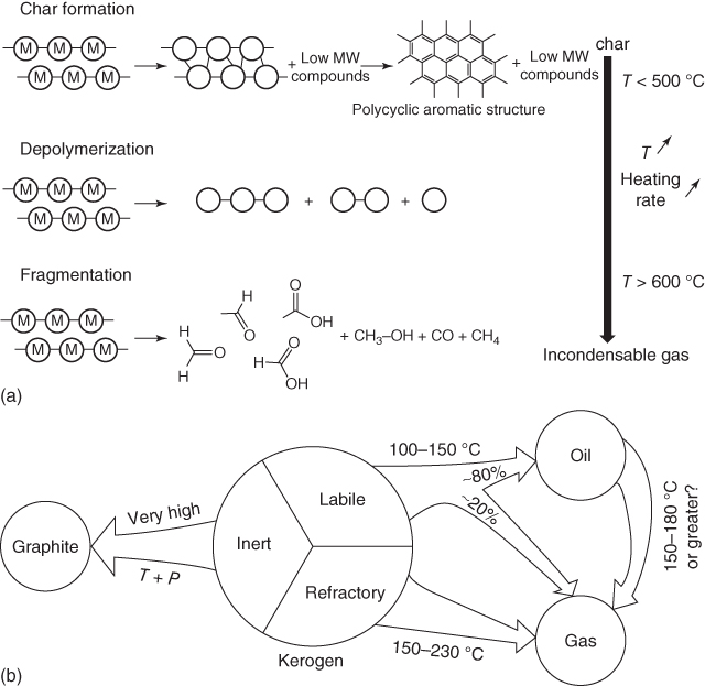
Figure 6.3 Geochemical degradation of polymeric biomaterial forms new bonds, resulting in char, or cleaves bonds via depolymerization or fragmentation (a). The heavier, insoluble portion that results from this initial degradation process can be characterized as labile, inert, or refractory depending on its composition and final state (b).
Source: (a) Collard and Blin [9]. Reproduced with permission from Elsevier; (b) Killops and Killops [10b]. Reproduced with permission from John Wiley & Sons.
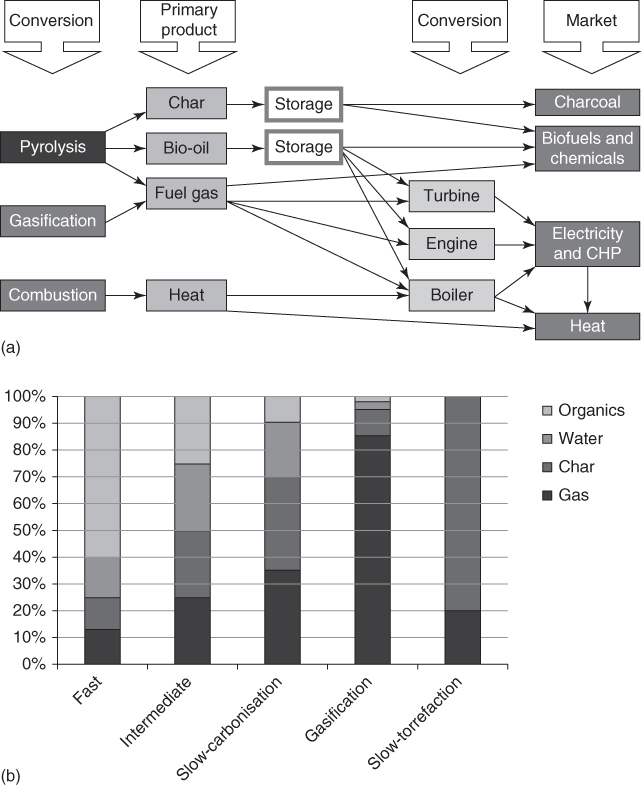
Figure 6.4 Biomass conversion into products including carbons, fuels, and energy, based on the conversion method chosen (a), and fraction of products based on the conversion method (b).
Source: Bridgwater 2012 [11]. Reproduced with permission from Elsevier.
The degradative processes described above are applied to the most abundant components of organic matter (biomass), which are polysaccharides, lignin, proteins, and lipids. The fate of these molecules over the course of geochemical and pyrolytic degradation will largely depend on their heteroatom content and degree of unsaturation of CC bonds. Complex molecules, such as polysaccharides, lignin, and proteins, mostly form larger polyaromatic carbon compounds, owing to chemical moieties that are susceptible to cleavage. These moieties can combine to form small molecules, leaving dangling bonds on the remaining molecules, which may then cross‐link (Figure 6.5) [12]. This process is ubiquitous in the cooking of foods in the form of caramelization and so‐called “browning,” whereby polyaromatic flavor compounds are formed. In fact, partially decomposed organic matter in the form of peat is burned to infuse polyaromatic “smoky” compounds in scotches [13], but can also be used as an effective fuel [14] or even a partially graphitic carbon precursor [15].

Figure 6.5 Steps in the graphitization for lignin and cellulose. (a) Lignin's aromatic rings cross‐link through substituents intermolecularly consolidating into a small molecule, like methanol. (b) Cellulose undergoes a similar process, but often starts with desaturation of the carbons.
Source: Collard and Blin 2014 [9]. Reproduced and redrawn with permission from Elsevier.
The one type of organic matter not included in the above discussion is lipids, which is primarily comprised of alkyl moieties and contain few unsaturated bonds. In the geochemical and pyrolytic conditions described above, lipids are mostly transformed into relatively short gaseous and liquid hydrocarbons, which are the primary components of natural gas and oil [10], making them a notably less‐effective precursor for partially graphitic carbons.
If the guiding principles that dictate that lipids will be inefficient partially graphitic carbon precursors as compared with compounds like proteins and polysaccharides continue to be valid for synthetic polymers, a naïve first approach of using a polymer like polyethylene (PE) would be unsuccessful. Indeed, although PE may seem like a reasonable precursor because it primarily comprised carbon atoms, its linear, nonaromatic arrangement and lack of heteroatoms mostly result in gasification because it does not have clear reactive pathways to cross‐link and form aromatic rings [2, 16]. However, in spite of PE's ineffective structure and composition for forming pyrolytic carbons, it would be very desirable to make carbons from such polymers as a means of recycling plastic waste [17], so one may reasonably ask what conditions could force PE into producing a partially graphitic carbon. To this end, there are reports of successful conversion of PE to carbon materials, often through a combination of metal catalysts, moderate pyrolytic temperatures, and pressures as high as 5 atm [7d, 7e].
The more effective carbon precursors from biomass are akin to cellulose or lignin, which may contain heteroatoms, cyclic structures, or unsaturated bonds [18]. Although these moieties do not guarantee a polymer's efficacy as a carbon precursor (e.g. polystyrene (PS)), they are present in most polymers that can act as efficient carbon precursors. With that said, the chemical functionalities present in polymers like polystyrene can be used to form cross‐links with an added cross‐linker, thereby dramatically improving pyrolysis yields [16a, 16b, 19]. A highly studied example of such a polymer is polyacrylonitrile (PAN), which contains unsaturated bonds and nitrogen as side groups and is industrially used as a precursor to carbon fibers [7c, 20]. PAN's nitrile groups act as reactive moieties to effectively cross‐link the polymer before reaching pyrolytic temperatures (Figure 6.6) [21]. These so‐called “stabilized” PANs subsequently fuse to form partially graphitic carbons at pyrolytic temperatures under inert atmosphere. Other polymers with similar features, like unsaturated bonds or nitrogen content, including polyaniline [22] and polyimides [23] have also been successfully applied to forming carbon through thermal cross‐linking, but even more polymers may be used as precursors when one uses other cross‐linking methods (Table 6.1).

Figure 6.6 Oxidative stabilization of PAN self‐cross‐links the polymer, after which the formed ladder polymers under pyrolytic conditions fuse together through a variety of eliminations [7c].
Table 6.1 Examples of precursors used for producing carbons with corresponding stabilization methods.
| Carbon source polymer | Stabilization methods | References |
| PAN | Thermal self‐cross‐linking in air | [7c, 21] |
| Polyaniline | Thermal cross‐linking, phytic acid, organophosphonic acids, phosphonic acid | [22, 24] |
| Polypyrrole | Thermal cross‐linking | [25] |
| Phenolic resin | Chemical curing, thermal cross‐linking | [26] |
| Poly(furfuryl alcohol) | Chemical curing, thermal cross‐linking, | [26b] |
| Resorcinol formaldehyde | Polycondensation, sodium carbonate gelation, HCl gelation | [27] |
| Poly(divinylbenzene) | FeCl3 hyper‐cross‐linking | [28] |
| Poly(vinylbenzyl chloride) | FeCl3 hyper‐cross‐linking | [29] |
| Polyimide | Thermal cross‐linking | [23b, 30] |
| Poly(vinyl pyridine) | Resol cross‐linking | [31] |
| Polyacrylamide | Thermal cross‐linking | [32] |
| Poly(o‐phenylenediamine) | FeCl3 cross‐linking | [33] |
| Poly(1,1‐dichloroethene) | Water‐in‐monomer emulsion polymerization | [34] |
| Polystyrene | UV cross‐linking, carbonyl cross‐linking, divinyl benzene (DVB) cross‐linking by Friedel−Crafts alkylation | [16a, 16c, 35] |
| Poly(methyl vinyl ketone) | Acid‐catalyzed thermal self‐cross‐linking | [7f] |
6.2 Carbon Catalysts Derived from Non‐templated Synthetic Polymers
An effective carbon catalyst has to have properly tuned features, including its degree of crystallinity [36], surface area/active site accessibility [37], and heteroatom content [38]. The crystallinity of a resulting carbon will depend on the pyrolysis conditions [38a] as well as the specific microstructure of the polymer precursor used [39].
Carbons for catalysis also need porosity to maximize catalytically active surface area and thereby overall effectiveness. Porosity can come in any size, but different size ranges will come from different mechanisms. Microporosity, with pore diameters <2 nm, can typically originate from imperfect packing of the polymer, or post‐pyrolysis chemical activation, which “etches away” part of the material, with potential impact on catalytically active functionalities [40]. Microporosity can also be achieved through the use of cross‐linkers, which may induce additional free volume between polymer chains [24a, 41]. Lastly, microporosity can come from reactive components in the precursor, such as halogens, forming micropores during pyrolysis [32, 42]. Mesopores (i.e. pores with diameters between 2 and 50 nm), on the other hand, are difficult to form without the aid of templates or some other means of inducing structure [43]. One way to introduce mesoscale features without resorting to the use of templates may involve the use of supramolecular structure, such as that present in polymer fibers used as precursors of carbon fibers [7b, 7c, 20, 44]. More recently, carbonization of polymer fibers has been explored as a simple way to fabricate nanostructured carbons for advanced chemical applications [7f, 24c, 25, 45]. Other template‐free methods typically use a solvent to create a structure, for example, by drying or solvent‐induced phase separation [46].
Another important factor for catalytic applications is the controlled incorporation of heteroatoms. Some methods for heteroatom incorporation include the use of heteroatom‐rich precursors [7c, 47], cross‐linking/non‐cross‐linking pre‐pyrolysis additives [24a, 48], or post‐pyrolysis modifications, like ball milling or ammonia activation [49]. Although each of these methods generally work, their choice depends on their effectiveness for target chemical functionality/degree of specificity. Post‐pyrolysis treatment will more readily add surface groups in a “pendant” manner over getting imbedded into the graphitic domains, and specificity over particular heteroatom chemical states will be limited. In preexisting carbon systems, post‐pyrolysis treatments have the advantage of relatively easy implementation and no changes to the synthesis of the original carbon [49c].
Pre‐pyrolysis heteroatom incorporation, although requiring more careful initial designing, is generally more effective in their introduction and can offer more specificity with regard to their resulting chemical states. Furthermore, any thoroughly mixed additive to the pre‐pyrolysis system could alter the atomic‐scale structure of the polymer and, as a result, could impact the carbon structure beyond adding the heteroatom [50]. The way an additive is incorporated in the polymer is likely a strong factor in the resulting heteroatom doping in carbon, allowing for control of the specificity of its incorporation is [24a, 51]. Heteroatom‐rich polymers provide even more control in producing a heteroatom‐doped carbon, depending on where that heteroatom fits in the pyrolysis mechanism [7c, 49a, 52]. As discussed earlier, the pyrolysis mechanism of PAN leads to the incorporation of nitrogen through the fusion of ladder polymers, followed by continued fusion of graphitic sheets [7c]. Other examples either have heteroatoms already imbedded into a cyclic group [49a, 52], like polypyrrole [25, 53], or into a backbone between cyclic groups [54], like polyaniline [22, 55].
As described above, although the use of polymer precursors offers considerable degree of control of graphitization and heteroatom content, it is rather limited with regard to micro/meso/macroscale porosity, which may limit the overall utility of resulting carbons. In the remaining sections, we describe various templating methods that overcome this shortcoming.
6.3 Hard Templating of Polymer‐Derived Carbons
Hard templating involves combining a carbon precursor with a thermally stable nanostructured component, which can be removed after carbonization. Although this approach is attractive owing to its simplicity, its use with polymers is often limited by the polymer solution's or melt's ability to infiltrate nanoscale spaces (Figure 6.7). One way to overcome this is by using poly(ionic liquid)s, which, when properly designed, exhibit excellent surface wettability [57]. To entirely circumvent the difficulties associated with polymer infiltration, monomers can be incorporated into the hard template followed by in situ polymerization. The simplest and most common use of this method involves mixing/infiltration of the monomer with the template, polymerization, pyrolysis, and finally removal of the template [58]. Owing to its effectiveness at retaining the nanostructure, various modifications of this procedure, which depend on the specific types of materials used and their intended applications, are used to synthesize a majority of hard templated carbons [36, 55a, 56].

Figure 6.7 Methods for infiltration of a polymer into a hard template. Limitations for each method are based on template feature sizes, tortuosity, and solution/melt properties. This can also apply to monomer infiltration but is generally easier.
Source: Martin et al. 2012 [56d]. Reproduced with permission from Elsevier.
Yet, another method of introducing the polymer into a hard template, which may assure its more uniform distribution, involves growing polymer chains from initiator sites pre‐introduced on the template surface, as illustrated by polymerization of acrylonitrile inside SBA‐15 mesoporous silica followed by graphitization and template removal in Figure 6.8 [59]. Uniformity between the polymer and template is especially important with non‐monolithic dispersed templates, like silica nanoparticles, which could otherwise yield a wide range of pore sizes. Furthermore, by chemically linking polymers and silica nanoparticles, the system can be solution processed and cast as films [60]. Grafting the polymer from the nanoparticles using surface‐initiated controlled polymerizations allows for structural control through control of the degree of polymerization (DP) (Figure 6.9) [59d].

Figure 6.8 TEM images taken at different angles of carbon templated by SBA‐15. The carbon was synthesized by grafting polyacrylonitrile from SBA‐15 using surface‐initiated controlled polymerization, followed by thermal treatment.
Source: Kruk et al. 2005 [59a]. Reproduced with permission from American Chemical Society.

Figure 6.9 Poly(4‐cyanostyrene)‐grafted silica nanoparticles using SI‐ATRP. Grafting the polymer from silica nanoparticles provides control over the resulting structure based on the diameter of the grafted nanoparticles.
Source: Lamson et al. [59d]. Reproduced with permission from John Wiley & Sons.
Although the use of hard templates is attractive partly because of their chemically inert nature, it is still possible that their presence could adversely affect the polymerization process or the subsequently formed microstructure. For example, one might be concerned that polymerization in confined spaces, like those found in mesoporous silica, would affect the way polymerization proceeds. However, it has been shown that surface‐initiated ATRP (SI‐ATRP) within such an environment could still proceed with high level of control, yielding narrowly distributed grafted chains [59a, 61].
The interaction of incorporated polymers with the hard template may affect the polymer's microstructure near the interface [62]. As this interaction is strongest at the template/polymer interface, any induced perturbations to the microstructure of the resulting carbon would be primarily near any surface exposed after template removal [36, 63]. Although such interactions may have a positive effect on the resulting carbon, such as improved crystallinity (Figure 6.10) [36], the overall phenomena as they apply to polymer‐derived carbons are relatively unexplored. For polymer systems, in general, there are indications that polymers are susceptible to confinement effects, the extent of which will depend on polymer backbone rigidity, resulting in modified glass transition temperatures and local ordering [63a]. There are also reports of confinement affecting polymer crystallization, and surface interactions affecting the microstructure of a polymer near that surface [63e–g]. Despite the wealth of evidence in general polymer systems, the extent of the impact of confinement/interfacial effects on pyrolysis and properties of the resulting carbon is still largely unexplored.

Figure 6.10 Template confinement by anodic aluminum oxide (a) resulted in increased crystallinity for carbon nitride nanorods (CNRs) as compared with its bulk g‐C3N4 counterpart, as shown by X‐ray diffraction (XRD) (b).
Source: Li et al. 2011 [36]. Reproduced with permission from American Chemical Society.
The last step to prepare hard templated carbons is removal of the template, which is achieved most often by post‐pyrolysis etching using HF, NaOH, or HCl [36, 58a, 64]. Use of etching, however, is associated with some complications. With respect to scaling up synthesis to industrial levels, such treatment is not desirable for safety, environmental effects, and cost. Furthermore, harsh chemical treatment could also remove desired functionalities from the templated carbon; HF, for example, has been shown to remove oxygen from carbon nanotubes [65]. With the effects of confinement/templates on carbon microstructure, the question about the impact of etching on surface functionalities of resulting nanocarbons is still largely unexplored. Having said that, it could be addressed by simply comparing untemplated or soft templated carbons before and after they have undergone etching procedures.
Unfortunately, elucidating the result of interactions between templates and polymers on the resulting carbon's microstructure is not a straightforward task because of the difficulties associated with designing and synthesizing a directly analogous system. One such set of systems does exist, in which the carbons can be derived from PAN grafted from either silica nanoparticles or cross‐linked poly(methyl methacrylate) (PMMA) (Figure 6.11) [66]. The precursors only differ by the composition of their cores and the sites that link PAN to the nanoparticle. Comparison between these two systems could also potentially aid in assessing the effects of etching, as the PMMA core does not survive pyrolysis [66a, 67].

Figure 6.11 PAN grafted from silica nanoparticles to produce carbons with precisely sized mesopores (a). This method is directly comparable with synthesizing carbon from PAN grafted from cross‐linked PMMA spheres (b).
Source: (a) Tang et al. 2008 [60]. Reproduced with permission from John Wiley & Sons. (b) Wu et al. 2014 [66a]. Reproduced with permission from John Wiley & Sons.
As discussed, many questions are still surrounding the details associated with hard templates and the more subtle effects they may have on the resulting carbon. Regardless, hard templating has been and continues to be a very valuable structuring approach, and addressing these questions would further improve the method's utility.
6.4 Soft Templated Carbons
Soft templating is characterized by non‐bonding interactions driving the formation of a nanostructure where there is no “rigid” phase. The dynamic nature of soft templating opens up new possibilities for carbon synthesis that would be difficult to achieve otherwise, such as graded porosity (Figure 6.12) [31]. The non‐bonding interactions that spontaneously induce structure are weak compared with hard templates, making the formed nanostructure susceptible to transitioning into disorder at higher temperatures. For this reason, the nanostructure must be stabilized before thermal energy weakens phase separations, or transitions completely to a disordered system, which is achieved by covalently cross‐linking a portion of the system [68]. Producing large surface area carbons requires the precursor to have high interfacial energy between phases. This energy is another source of structural instability, potentially inducing structural collapse at high temperatures when the polymer has not been sufficiently cross‐linked (Figure 6.13) [69].

Figure 6.12 Soft templating induces structure dynamically and thereby can be used to create a feature gradient. In this example, a concentration gradient was induced by evaporation of the solvent, which was then converted into a structural gradient by submerging in deionized water.
Source: Hesse et al. 2015 [31]. Reproduced with permission from American Chemical Society.
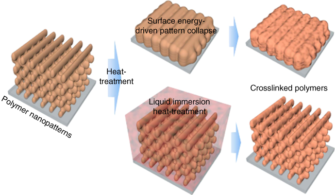
Figure 6.13 Multi‐beam interference lithography was used to 3D pattern a SU8 photoresist. The large surface area polymer pattern without a support or sufficient cross‐linking can collapse during the thermal treatment necessary to produce carbons. Liquid immersion reduces the surface energy of the polymer, so the resulting heat‐treated polymer does not collapse.
Source: Kang et al. 2015 [69]. Reproduced with permission from Springer Nature.
6.4.1 Block Copolymer Templating
With their synthesis initially enabled by living polymerization methods, block copolymers (BCPs) have been extensively studied for their nanoscale structural properties [70]. BCPs with appropriately chosen blocks may then form nanostructures that can be retained through the pyrolysis process (Figure 6.14) [72]. The specific nanostructures formed are dependent on and very sensitive to the volume fraction of each block, and for this reason, the development of the BCP‐templating method has largely been enabled by the development of controlled polymerization techniques, such as ATRP (Figure 6.15) [71].

Figure 6.14 Atomic force microscopy (AFM) images of (AN)45‐(BA)530‐(AN)45 ultrathin films spin‐coated onto silicon at different stages of treatment, all showing retained morphology: (a) thermal annealing under vacuum, (b) pyrolysis at 600 °C, and (c) pyrolysis at 1200 °C.
Source: Kowalewski et al. 2002 [71a]. Reproduced with permission from American Chemical Society.

Figure 6.15 The morphology of carbon produced from block copolymer templating is directly resulted from microphase separation between the blocks. This method is a conceptually simple way to produce carbons with structures varying from spheres to sheets.
Source: Zhong et al. 2014 [73]. Reproduced with permission from Royal Society of Chemistry.
With BCP templating, the BCPs can be used as both a template and a carbon source, or as just a template [74]. In fact, many hard templates themselves are formed by templating with copolymer systems, such as PEO‐b‐PPO‐b‐PEO [74a], so it is logical to try to circumvent the use of a hard template and use the BCP directly. This can be achieved using a carbon source separate from the BCP, often a small molecule that mixes preferentially with one of the blocks (Figure 6.16) [67a, 75]. The polymer template is removed concomitantly with pyrolysis, eliminating any post‐pyrolysis removal steps that would be required with hard templating.

Figure 6.16 Block copolymers can be used to drive the formation of a nanostructure without being the source of carbon themselves. The carbon precursor, dopamine, preferentially occupies space within the PEO phase, resulting in a carbon with pores produced by degradation of the PS phase.
Source: Tian et al. 2016 [75d]. Reproduced with permission from John Wiley & Sons.
BCPs can also be used as a stand‐alone system, with one block acting as the carbon source and the other as the sacrificial component. The use of a single BCP for both roles requires choosing a polymer block that can cross‐link and ultimately graphitize, whereas the other block either volatilizes or decomposes [72a]. Sacrificial blocks commonly contain oxygen, like PEO (poly(ethylene oxide)) [35], PMMA [49b], PBA (poly(butyl acrylate)) [40, 76], or PAA (poly(acrylic acid)) [71b], but they may also comprise other non‐cross‐linked polymers, like PS [77].
The carbons yielded from BCP templating should then have a structure with voids in the space previously occupied by the sacrificial block; therefore, the resulting mesoscale surface area depends on the interfacial area between blocks. Thus, to maximize the surface area, it would be logical to try to reduce the size of features like pores, which is easily realized with BCP templating through the use of smaller overall block lengths [78]. This strategy ends up being limited in efficacy in some cases though because the stability of its nanostructure is determined by incompatibility of the blocks and DP. The interfaces that are formed between blocks need to be sharp to provide a robust carbon structure, and to help retain nanostructure at higher temperatures, so reducing the polymer length too much leads to pore collapse (Figure 6.17). Another way the nanostructure structure can be lost is through the interactions with the substrate surface when forming a thin film. These interactions can overwhelm the nanostructure of thin films, resulting in a loss of the desired morphology (Figure 6.18) [38a].

Figure 6.17 By synthesizing BCPs with longer or shorter overall DPs (while maintaining block ratios), morphology remains consistent but produces different feature sizes that translate to pore sizes of resulting carbons. At lower DP, reduced strength in microphase separation causes less sharp boundaries between block phases, rendering some carbon pores inaccessible due to collapse.
Source: Kopec et al. 2017 [78]. Reproduced with permission from American Chemical Society.

Figure 6.18 Surfaces of PAN‐b‐PBA films of varying thickness were measured by AFM before and after thermal stabilization/pyrolysis and image‐processed to group interconnected segments. The AFM images and an overlay of interconnected domains differentiated by color are shown to the left for the thickest and thinnest films. The pixel sizes of the largest interconnected segment for all BCPs and subsequently pyrolyzed films are shown to the right.
Source: Zhong et al. 2014 [38a]. Modified and reproduced with permission from Royal Society of Chemistry.
The mechanism that provides BCP templating with its flexibility is also a source of limitation for the variety of structures attainable. Combining features, like micropores and mesopores, is achievable because of the different mechanisms that produce them, but yielding other features like macropores or open pore structures typically necessitates the use of additional templating methods. Although more complicated systems like triblock systems [31, 79] can be used to produce other morphologies, the templating is still driven by phase separation. This means that the robustness of the structures is governed by the immiscibility of the blocks, making the targeting smaller structural features still difficult [78].
6.4.2 Templating Through Polymer Architecture
A common challenge with BCP templating is retention of morphology when attempting to use shorter polymers and/or to fabricate ultrathin film structures. One approach to improve the structural stability of a templated polymer system is the use of covalently linked architectures. The ability to create complex polymeric architectures is one of the many unique aspects of controlled polymerization methods, and owing to the covalent linkages that partially induce their overall ordering, the nanostructures of such polymer precursor systems are generally less susceptible to weakening phase boundaries or transitioning into disorder [80]. These polymer architectures include stars, brushes, and dendrimers [81]. In bottlebrush polymers with BCP arms, for example, the exterior block can be either sacrificial or a carbon precursor. The former results in a protective shell to isolate the cores from fusing during pyrolysis [82] and the latter localizes the sacrificial component near the backbone while carbonizing block forms an interconnected structure with other brushes (Figure 6.19) [83]. The strong steric repulsion that comes from covalent linkages and high grafting density successfully hinders partial miscibility typical of low‐DP BCPs.

Figure 6.19 Bottlebrush polymers can be used to form carbons from either an interior carbon source block (a) or exterior (b). The bottlebrush architecture causes strong steric repulsion, preventing partial miscibility that can limit the formation of high surface area carbons from low‐DP BCPs.
Source: (a) Tang et al. 2007 [82]. Reproduced with permission from American Chemical Society. (b) Yuan et al. 2017 [83]. Reproduced with permission from Elsevier.
6.4.3 Amphiphilic Templating Methods
The structures produced by the soft templating methods discussed so far are determined by the architecture and composition of mostly single units. This limits the size of features that can be produced because the length scale of structuring that occurs in such systems cannot be larger than the length scale of the polymers themselves. In order to achieve templating on longer length scales, one can resort to utilizing interactions between the template and solvents. Methods utilizing this principle include sol–gel polymerization [52, 84], zeta potential [85], and various emulsions [86], like miniemulsions [87], water‐in‐oil emulsions [34], inverse emulsions [27a], and high internal phase emulsions [28, 88].
In these methods, through competing interactions with a solvent, templates arrange into structures with feature sizes that may depend on solution concentrations and not just the length of the polymer chains. Particulate structures, for example, can be formed by hydrophilic/hydrophobic interactions of components in solution spontaneously arranging into either spheres or vesicles (Figure 6.20) [75b]. As the nanostructures are formed by polymer–solvent interactions, the size of the resulting carbon particles will depend on the concentrations of the components that make up the pre‐pyrolyzed structures (Figure 6.21) [86b].

Figure 6.20 A block copolymer and hydrophobic small‐molecule carbon source in water will spontaneously form vesicles with the carbon source occupying space within the more hydrophobic polymer block. Wall thickness can be tuned by changing the length of blocks within the BCP, and diameter can be modified by changing concentrations.
Source: Yang et al. 2013 [74b]. Reproduced with permission from American Chemical Society.

Figure 6.21 Water‐in‐oil emulsion with a hydrophobic carbon source can be used to produce spherical polymeric precursors, and by controlling the amount of emulsifier compared with precursor, size can be controlled.
Source: Kwon et al. 2014 [86b]. Reproduced with permission from John Wiley & Sons.
This approach can also be used in multistep structuring, whereby structured stabilized spheres can be used as building blocks for further organization. Before carbonization, the individual particles can be assembled into larger structures by cross‐linking between particles, producing a network with shape persistence through pyrolysis (Figure 6.22) [87b]. This approach comes with an additional degree of control when 3D structure nanoscale “building blocks” are first synthesized, followed by a separate step of assembly into an overall structure.

Figure 6.22 Pluronic P123 (PEG‐b‐PPG‐b‐PEG) (poly(ethylene glycol), PEG; poly(propylene glycol), PPG) can be used to stabilize microemulsion polymerization to produce nanoparticles. The nanoparticles are then hyper‐cross‐linked to form a 3D network that is maintained through pyrolysis, resulting in a carbon aerogel.
Source: Xu et al. 2017 [87b]. Reproduced with permission from Elsevier.
In contrast to producing monolithic structures by multistep assembly of spheres, amphiphilic templating can produce open, porous structures in a single structuring step by templating from polymerized high internal phase emulsions (polyHIPEs) (Figure 6.23) [28, 34, 88, 89]. PolyHIPE precursors can produce carbons with multi‐length‐scale pore structures without the use of multiple templating methods or steps. The resulting open pore structures can be effective for catalysis applications where mass transport is a limiting factor [90].


Figure 6.23 Carbons produced from polyHIPEs can exhibit very open pore structures with as much as 91% open volume. The extent of hyper‐cross‐linking can be used to further control the resulting carbon, depending on the desired final structure. (A) A scheme showing polyHIPEs (a), which is hyper‐cross‐linked (b), or simply pyrolyzed (c). Pyrolyzing hyper‐cross‐linked polyHIPEs (d) will contain granularity that is not present when not hyper‐cross‐linked. (B) Experimental SEM of polyHIPEs with letters corresponding to the state described by the scheme.
Source: Reproduced with permission from Ref. [28].
6.5 Templating by Carbon/Polymer Hybrids
A different approach available to making templated carbons starts with an already produced graphitic material, like carbon nanotubes (Figure 6.24). As discussed in the previous sections, high temperatures required to make carbon materials can be limiting when trying to produce high surface energy materials or materials with moieties susceptible to thermal degradation. By starting with a carbon, functionalization may be achieved by incorporation and subsequent pyrolysis of a polymer under more moderate conditions [91]. This approach can be attractive to maximize the amount of functional moieties that either may not survive higher pyrolysis conditions or are lost progressively during pyrolysis. Such “hybrid” templating methods can use chemical modifications of pre‐formed carbons to graft polymers [92], or polymers can be adsorbed onto the carbon surface [91b, 91c, 93]. Hybrid templating can effectively meld the properties of an already formed carbon, such as conductivity, with functionalities provided by pyrolyzing a polymer, like heteroatoms or increased surface area [93b, 94]. The combination of conductivity and active sites has been especially effective at enhancing the electrocatalytic activity of otherwise semiconducting materials like g‐C3N4 for hydrogen evolution and even CO2 reduction [95].

Figure 6.24 Polystyrene grafted from carbon nanotubes by SI‐ATRP was hyper‐cross‐linked and pyrolyzed to produce a carbon with a mesoporosity arising from the organization of nanotubes, and with microporosity from the cross‐linked PS.
Source: Liang et al. 2017 [19b]. Reproduced with permission from Royal Society of Chemistry.
6.6 Polymer‐Derived Carbons as Catalysts
Although carbon materials have played many important roles in catalysis, carbons derived from polymeric precursors are particularly suited for exploring fundamental principles of metal‐free catalysis in carbon systems, owing to their well‐defined and tunable nature. Carbon tunability is especially important when trying to understand structure–activity relationships because interdependency between properties of a precursor and resulting carbon makes it difficult to “deconvolute” effects of individual factors. One way to achieve it would be to continuously vary a parameter within the synthesis of a carbon (e.g. pyrolysis temperature or precursor polymer length), with the goal of obtaining useful insights through correlation of material properties and catalytic activities.
One example of such an approach comes from studies of BCP‐templated nanocarbons discussed in Section 6.4.2 [38a, 96]. Carbons synthesized from the same PAN‐b‐PBA precursor exhibited N:C ratios and conductivities that changed smoothly with pyrolysis temperature (Figure 6.25a) while maintaining the same nanostructure (Figure 6.25b) [38a, 96]. Evaluation of their catalytic activity in the oxygen reduction reaction (ORR) reveals the optimal performance for samples pyrolyzed at 800 °C (Figure 6.25c). Such an optimum in catalytic activity was interpreted as an interplay between the improvement of electrical conductivity with pyrolysis temperature facilitated by the increase in graphitic domain size, which was countered by the decrease in nitrogen content concomitant with the fusion of graphitic domains. To reiterate, the difficulty associated with making such a seemingly simple conclusion stems from the complex heterogeneous nature of the materials. Carbons yielded from the same carbon source (PAN) can exhibit very different catalytic behaviors, and even carbons from the exact same precursor can have different activities based on processing parameters like catalyst loading (Figure 6.26) [38a].

Figure 6.25 The effect of pyrolysis temperature on N:C ratio and conductivity for carbons from PAN‐b‐PBA (a). The nanostructure of the resulting carbons remained consistent across pyrolysis temperatures, as shown by radial profiles of azimuthally averaged small‐angle X‐ray‐scattering patterns (b). Tested as binder‐free catalysts for ORR, all carbons showed activity, but those produced by pyrolysis at 800 °C exhibited optimal performance.
Source: (a, c) Zhong et al. 2014 [38a]. Reproduced with permission from Royal Society of Chemistry. (b) Zhong et al. 2012 [96]. Reproduced with permission from Royal Society of Chemistry.

Figure 6.26 A plot showing the effect of catalyst loading on onset/half‐wave overpotential (ηos:ηhw) for copolymer‐templated nitrogen‐enriched carbons (CTNCs) pyrolyzed at 700 °C (a). Numbers below individual points correspond to measured average number of electrons transferred. Comparison of estimated film densities with bulk CTNCs (b), indicating low loadings resulted in collapse of nanostructure.
Source: Zhong et al. 2014 [38a]. Reproduced with permission from Royal Society of Chemistry.
One of the particularly important questions in the area of metal‐free catalysis is to what extent the system is truly metal‐free. Carbon systems can be extremely sensitive to trace metal exposure, completely altering their perceived catalytic activity [97]. Two major potential sources of such exogenous, not fully accounted for metal species can be residual metal‐based catalysts used in the synthesis of the polymeric precursor, or the electrodes used in electrocatalytic experiments [98]. Thus, for proper interpretation, special care must be taken to remove any residual metals from the polymer by extensive purification and to provide rigorous assessment of metal content through sufficiently sensitive techniques (parts per billion atomic resolution) such as inductively coupled plasma mass spectrometry [99]. Comparison with analogous polymer precursors synthesized by strictly metal‐free means (e.g. reversible addition fragmentation polymerization as opposed to ATRP [100]) may also be useful.
An example of a system in which the use of a metal electrode may inadvertently be the source of activity is the hydrogen evolution reaction (HER), which is often performed under acidic conditions using a platinum counter electrode. Under such conditions, Pt will dissolve into the electrolyte and can subsequently deposit onto the carbon working electrode [97d]. This deposition process is greatly enhanced by pyridinic nitrogens, which can coordinate Pt2+, acting as nucleation sites for Pt nanoparticles (Figure 6.27) [38b]. Although this is problematic when catalytic activity of a carbon is purportedly metal‐free, it is also an opportunity to improve Pt/C catalysts and other metal/C systems. Through nanostructuring in conjunction with heteroatom sites, more efficient catalysts per precious metal atom may be attained, either through metal nanoparticles or “molecular” metals. Furthermore, carefully chosen coordinating sites can improve stability of the metals as compared with current metal/C systems [97b].

Figure 6.27 Hydrogen evolution by a metal‐free catalyst was dramatically enhanced by the use of a Pt counter electrode (a). X‐ray photoelectron spectroscopy revealed a shift in the distribution of N‐binding energies, whose density functional theory confirmed to be due to Pt coordinating to pyridinic nitrogen in the carbon (b).
Source: Gottlieb et al. 2016 [38b]. Reproduced with permission from American Chemical Society.
Beyond being very useful as materials for fundamental structure–activity studies, some polymer‐based systems have already been shown to exhibit levels of activity pointing to their viability in large‐scale applications. The key factor in this instance is the overall cost and scalability of fabricating the carbon‐based catalyst. A promising example to this end is untemplated synthesis of carbons from polyaniline and phytic acid, which have been shown to exhibit large surface area and efficient performance in ORR and oxygen evolution reaction (OER) [24a]. The entire process comprised polymerization, aerogel formation by freeze‐drying, and pyrolysis. The absence of a hard template and etching, complicated synthetic schemes for soft templating, or post‐pyrolysis activation means the entire process is extremely simple.
Use of polymer precursors may also provide a path to eliminate binders and additives commonly used in the fabrication of electrodes. In addition to adding to the cost and complexity of fabrication, the use of binders decreases the amount of active material, and their presence may hinder mass transport and/or partially block the active sites [24c, 101]. Simple methods to avoid binders include electrodeposition or “growing” polymer precursors from a carbon paper electrode and do not add any other complications. The solution processability of polymeric precursors can be used in other ways to produce binder‐free electrodes, for example by simple drop casting onto a thermally stable electrode [38a].
6.7 Conclusions and Outlook
This chapter provided a “molecule maker's” perspective on the use of polymers, particularly those prepared by controlled polymerizations, as precursors for catalytic nanostructured carbons. The main advantage of the use of such precursors is that they allow for high level of control of the nanostructure and of the incorporation of heteroatoms critical for the catalytic activity. The promise of heteroatom‐enriched nanocarbons as metal‐free catalysts was one of the most particularly exciting themes pursued in this field in recent years. It has to be kept in mind, however, that another promising route to highly efficient catalysts is purposeful incorporation of trace amount of metals [38b, 97b]. This is logical, given the effectiveness of platinum on carbon that, compared with the molecular and trace incorporations currently explored, is a fairly uncontrolled process [102]. Trace metal/carbon materials have recently been realized [38b] and interest in them as catalysts will continue to grow, owing largely to the increased sophistication of synthetic methods for producing nanostructured carbons.
Another important point that needs to be brought up is that that most synthetic polymers are derived from nonrenewable resources, and their synthesis can be quite energy intensive, especially when heteroatoms like nitrogen are incorporated. This leads to the question about the role they can play in comparison with abundant and inexpensive biomass precursors, especially in the context of sustainable energy‐related applications [97b].
The development of new catalysts revolves around two major problems: (i) discovery of the fundamental underpinnings of catalytic activity and (ii) the search of economically feasible, bulk commodity catalysts. Owing to their well‐defined structure in comparison with biomass‐derived systems, “designer” carbons afforded by sophisticated methods utilizing well‐defined polymer precursors may be an invaluable tool in the fundamental discovery process (i). The structure–activity relationships revealed through their explorations may then provide guidance for designing next‐generation commodity catalysts (ii) based on the abundant biomass precursors [103].
Acknowledgments
The NSF (DMR 1501324) is acknowledged for financial support.
References
- 1 Hirsch, A. (2010). Nat. Mater. 9: 868–871.
- 2 Pierson, H.O. (1993). Handbook of Carbon, Graphite, Diamond, and Fullerenes: Properties, Processing, and Applications. Park Ridge, NJ: Noyes Publications.
- 3 Georgakilas, V., Perman, J.A., Tucek, J., and Zboril, R. (2015). Chem. Rev. 115: 4744–4822.
- 4 (a) Rodriguez‐Reinoso, F. (1998). Carbon 36: 159–175. (b) Serp, P. and Figueiredo, J.L.S. (2009). Carbon Materials for Catalysis. Hoboken, NJ: John Wiley & Sons. (c) Serp, P. (2003). Appl. Catal. A Gen. 253: 337–358. (d) Zheng, Y., Liu, J., Liang, J. et al. (2012). Energy Environ. Sci. 5: 6717.
- 5 (a) Li, X., Cai, W., An, J. et al. (2009). Science 324: 1312–1314. (b) Gogotsi, Y., Libera, J.A., and Yoshimura, M. (2011). J. Mater. Res. 15: 2591–2594. (c) Chen, L., Hernandez, Y., Feng, X., and Müllen, K. (2012). Angew. Chem. Int. Ed. 51: 7640–7654.
- 6 (a) Yang, X., Dou, X., Rouhanipour, A. et al. (2008). J. Am. Chem. Soc. 130: 4216–4217. (b) Simpson, C.D., Brand, J.D., Berresheim, A.J. et al. (2002). Chem. Eur. J. 8: 1424–1429. (c) Scott, L.T. (2002). Science 295: 1500–1503.
- 7 (a) Peters, E.M. (1966). Heat‐resistant black fibers and fabrics derived from rayon. US Patent 3,235,323A; (b) Suzuki, M. (1994). Carbon 32: 577–586. (c) Bajaj, P. and Roopanwal, A.K. (1997). J. Macromol. Sci., Rev. Macromol. Chem. Phys. C37: 97–147. (d) Kim, K.W., Lee, H.M., Kim, B.S. et al. (2015). Carbon Lett. 16: 62–66. (e) Behr, M.J., Landes, B.G., Barton, B.E. et al. (2016). Carbon 107: 525–535. (f) Krumpfer, J.W., Giebel, E., Frank, E. et al. (2017). Chem. Mater. 29: 780–788.
- 8 (a) Matyjaszewski, K. and Tsarevsky, N.V. (2014). J. Am. Chem. Soc. 136: 6513–6533. (b) Matyjaszewski, K. (2012). Macromolecules 45: 4015–4039.
- 9 Collard, F.X. and Blin, J. (2014). Renew. Sust. Energ. Rev. 38: 594–608.
- 10 (a) Breger, I.A. (1966). J. Am. Oil Chem. Soc. 43: 197. (b) Killops, S.D. and Killops, V.J. (1993). An Introduction to Organic Geochemistry. Harlow, Essex, England/New York: Longman Scientific & Technical/Wiley.
- 11 Bridgwater, A.V. (2012). Biomass Bioenergy 38: 68–94.
- 12 Tissot, B.P. and Welte, D.H. (1984). Petroleum Formation and Occurrence, 2 (revised and enlarged edition)e. Berlin, New York: Springer‐Verlag.
- 13 Kleinjans, J.C.S., Moonen, E.J.C., Dallinga, J.W. et al. (1996). Lancet 348: 1731.
- 14 (a) Sjoestroem, K. and Chen, G. (1990). Ind. Eng. Chem. Res. 29: 892–895. (b) Blizard, J. (1917). The Value of Peat Fuel for the Generation of Steam. Ottawa: Government Printing Bureau.
- 15 Ding, J., Wang, H., Li, Z. et al. (2013). ACS Nano 7: 11004–11015.
- 16 (a) Wu, D.C., Hui, C.M., Dong, H.C. et al. (2011). Macromolecules 44: 5846–5849. (b) Li, Z., Wu, D., Liang, Y. et al. (2013). Nanoscale 5: 10824–10828. (c) Lee, W.H. and Moon, J.H. (2014). ACS Appl. Mater. Interfaces 6: 13968–13976.
- 17 Bazargan, A. and McKay, G. (2012). Chem. Eng. J. 195–196: 377–391.
- 18 (a) Sevilla, M. and Fuertes, A.B. (2009). Carbon 47: 2281–2289. (b) Yun, Y.S., Cho, S.Y., Shim, J. et al. (2013). Adv. Mater. 25: 1993–1998. (c) Suhas, Carrott, P.J., and Ribeiro Carrott, M.M. (2007). Bioresour. Technol. 98: 2301–2312.
- 19 (a) Ouyang, Y., Shi, H., Fu, R., and Wu, D. (2013). Sci. Rep. 3: 1430. (b) Liang, Y., Chen, L., Zhuang, D. et al. (2017). Chem. Sci. 8: 2101–2106.
- 20 Rahaman, M.S.A., Ismail, A.F., and Mustafa, A. (2007). Polym. Degrad. Stab. 92: 1421–1432.
- 21 Saha, B. and Schatz, G.C. (2012). J. Phys. Chem. B 116: 4684–4692.
- 22 Trchova, M., Matejka, P., Brodinova, J. et al. (2006). Polym. Degrad. Stab. 91: 114–121.
- 23 (a) Geiszler, V.C. and Koros, W.J. (1996). Ind. Eng. Chem. Res. 35: 2999–3003. (b) Suda, H. and Haraya, K. (1997). J. Phys. Chem. B 101: 3988–3994.
- 24 (a) Zhang, J., Zhao, Z., Xia, Z., and Dai, L. (2015). Nat. Nanotechnol. 10: 444–452. (b) Wang, C.L., Sun, L., Zhou, Y. et al. (2013). Carbon 59: 537–546. (c) Zhu, Y.P., Jing, Y., Vasileff, A. et al. (2017). Adv. Energy Mater. 1602928.
- 25 Wang, Z.H., Xiong, X.Q., Qie, L., and Huang, Y.H. (2013). Electrochim. Acta 106: 320–326.
- 26 (a) Jiang, D.E., van Duin, A.C., Goddard, W.A. 3rd, and Dai, S. (2009). J. Phys. Chem. A 113: 6891–6894. (b) Fitzer, E., Schaefer, W., and Yamada, S. (1969). Carbon 7: 643–648.
- 27 (a) Halama, A., Szubzda, B., and Pasciak, G. (2010). Electrochim. Acta 55: 7501–7505. (b) Hao, G.P., Li, W.C., Qian, D., and Lu, A.H. (2010). Adv. Mater. 22: 853–857.
- 28 Israel, S., Gurevitch, I., and Silverstein, M.S. (2015). Polymer 72: 453–463.
- 29 Castaldo, R., Avolio, R., Cocca, M. et al. (2017). RSC Adv. 7: 6865–6874.
- 30 Shah, H.V., Brittain, S.T., Huang, Q. et al. (1999). Chem. Mater. 11: 2623–2625.
- 31 Hesse, S.A., Werner, J.G., and Wiesner, U. (2015). ACS Macro Lett. 4: 477–482.
- 32 Puthusseri, D., Aravindan, V., Madhavi, S., and Ogale, S. (2014). Energy Environ. Sci. 7: 728–735.
- 33 Zhu, H., Wang, X., Liu, X., and Yang, X. (2012). Adv. Mater. 24: 6524–6529.
- 34 Alam, M.M., Miras, J., Perez‐Carrillo, L.A. et al. (2013). Microporous Mesoporous Mater. 182: 102–108.
- 35 Huang, J.Y., Tang, C.B., Lee, H. et al. (2007). Macromol. Chem. Phys. 208: 2312–2320.
- 36 Li, X.H., Zhang, J.S., Chen, X.F. et al. (2011). Chem. Mater. 23: 4344–4348.
- 37 Sahraie, N.R., Kramm, U.I., Steinberg, J. et al. (2015). Nat. Commun. 6: 8618.
- 38 (a) Zhong, M.J., Jiang, S.Y., Tang, Y.F. et al. (2014). Chem. Sci. 5: 3315–3319. (b) Gottlieb, E., Kopec, M., Banerjee, M. et al. (2016). ACS Appl. Mater. Interfaces 8: 21531–21538. (c) Kumar, B., Asadi, M., Pisasale, D. et al. (2013). Nat. Commun. 4: 2819.
- 39 Prilutsky, S., Zussman, E., and Cohen, Y. (2008). Nanotechnology 19: 165603.
- 40 Zhong, M., Kim, E.K., McGann, J.P. et al. (2012). J. Am. Chem. Soc. 134: 14846–14857.
- 41 Xiao, Z.C., Kong, D.B., Liang, J.X. et al. (2017). Carbon 116: 633–639.
- 42 (a) Xu, B., Hou, S.S., Chu, M. et al. (2010). Carbon 48: 2812–2814. (b) Xu, B., Wu, F., Chen, S. et al. (2008). Colloids Surf., A 316: 85–88.
- 43 (a) Gong, Y., Wei, Z., Wang, J. et al. (2014). Sci. Rep. 4: 6349. (b) Wu, M.B., Li, L.Y., Liu, J. et al. (2015). New Carbon Mater. 30: 471–475.
- 44 Zussman, E., Chen, X., Ding, W. et al. (2005). Carbon 43: 2175–2185.
- 45 (a) Park, S.H., Jung, H.R., and Lee, W.J. (2013). Electrochim. Acta 102: 423–428. (b) Jin, J., Shi, Z.Q., and Wang, C.Y. (2014). Electrochim. Acta 141: 302–310. (c) Yang, J., Xie, J., Zhou, X.Y. et al. (2014). J. Phys. Chem. C 118: 1800–1807.
- 46 (a) Wu, D.C., Fu, R.W., Zhang, S.T. et al. (2004). Carbon 42: 2033–2039. (b) Allahbakhsh, A. and Bahramian, A.R. (2015). Nanoscale 7: 14139–14158. (c) Okada, K., Nandi, M., Maruyama, J. et al. (2011). Chem. Commun. (Camb.) 47: 7422–7424.
- 47 Zhao, W.X., Han, S., Zhuang, X.D. et al. (2015). J. Mater. Chem. A 3: 23352–23359.
- 48 To, J.W., Chen, Z., Yao, H. et al. (2015). ACS Cent Sci. 1: 68–76.
- 49 (a) Su, Y.Z., Yao, Z.Q., Zhang, F. et al. (2016). Adv. Funct. Mater. 26: 5893–5902. (b) Yan, K., Kong, L.B., Shen, K.W. et al. (2016). Appl. Surf. Sci. 364: 850–861. (c) Jeon, I.‐Y., Choi, H.‐J., Jung, S.‐M. et al. (2013). J. Am. Chem. Soc. 135: 1386–1393.
- 50 Choi, C.H., Park, S.H., and Woo, S.I. (2012). ACS Nano 6: 7084–7091.
- 51 Pei, Z.X., Li, H.F., Huang, Y. et al. (2017). Energy Environ. Sci. 10: 742–749.
- 52 Kicinski, W. and Dziura, A. (2014). Carbon 75: 56–67.
- 53 (a) Qie, L., Chen, W.M., Xu, H.H. et al. (2013). Energy Environ. Sci. 6: 2497–2504. (b) Dubal, D.P., Chodankar, N.R., Caban‐Huertas, Z. et al. (2016). J. Power Sources 308: 158–165. (c) Niu, W.H., Li, L.G., Wang, N. et al. (2016). J. Mater. Chem. A 4: 10820–10827.
- 54 Yang, S., Peng, L., Huang, P. et al. (2016). Angew. Chem. Int. Ed. Engl. 55: 4016–4020.
- 55 (a) Silva, R., Voiry, D., Chhowalla, M., and Asefa, T. (2013). J. Am. Chem. Soc. 135: 7823–7826. (b) Ding, W., Li, L., Xiong, K. et al. (2015). J. Am. Chem. Soc. 137: 5414–5420.
- 58 (a) Huang, X., Zhou, L.J., Voiry, D. et al. (2016). ACS Appl. Mater. Interfaces 8: 18891–18903. (b) Liu, J., Wickramaratne, N.P., Qiao, S.Z., and Jaroniec, M. (2015). Nat. Mater. 14: 763–774. (c) Roberts, A.D., Li, X., and Zhang, H. (2014). Chem. Soc. Rev. 43: 4341–4356. (d) Martin, J., Maiz, J., Sacristan, J., and Mijangos, C. (2012). Polymer 53: 1149–1166. (e) Thomas, A., Goettmann, F., and Antonietti, M. (2008). Chem. Mater. 20: 738–755.
- 56 Fellinger, T.‐P., Thomas, A., Yuan, J., and Antonietti, M. (2013). Adv. Mater. 25: 5838–5855.
- 57 Han, S.J. and Hyeon, T. (1999, 1955‐1956). Chem. Commun.
- 59 (a) Kruk, M., Dufour, B., Celer, E.B. et al. (2005). J. Phys. Chem. B 109: 9216–9225. (b) Wu, D., Dong, H., Pietrasik, J. et al. (2011). Chem. Mater. 23: 2024–2026. c) Banerjee, S., Paira, T.K., Kotal, A., and Mandal, T.K. (2012). Adv. Funct. Mater. 22: 4751–4762. (d) Lamson, M., Chen, L., Zhong, M. et al. (2017). Macromol. Chem. Phys. 1600524.
- 60 Tang, C., Bombalskil, L., Kruk, M. et al. (2008). Adv. Mater. 20: 1516.
- 61 Kruk, M., Dufour, B., Celer, E.B. et al. (2008). Macromolecules 41: 8584–8591.
- 62 (a) Huber, P. (2015). J. Phys. Condens. Matter 27: 103102. (b) Michell, R.M., Lorenzo, A.T., Muller, A.J. et al. (2012). Macromolecules 45: 1517–1528. (c) Uyar, T., Rusa, M., and Tonelli, A.E. (2004). Macromol. Rapid Commun. 25: 1382–1386. (d) Candau, F., Braun, O., Essler, F. et al. (2002). Macromol. Symp. 179: 13–25.
- 63 (a) Shavit, A. and Riggleman, R.A. (2013). Macromolecules 46: 5044–5052. (b) Loo, Y.L., Register, R.A., Ryan, A.J., and Dee, G.T. (2001). Macromolecules 34: 8968–8977. (c) Muller, A.J., Arnal, M.L., Trujillo, M., and Lorenzo, A.T. (2011). Eur. Polym. J. 47: 614–629. (d) Ding, W., Wei, Z., Chen, S. et al. (2013). Angew. Chem. Int. Ed. Engl. 52: 11755–11759. (e) Larin, S.V., Falkovich, S.G., Nazarychev, V.M. et al. (2014). RSC Adv. 4: 830–844. (f) Trujillo, M., Arnal, M.L., Muller, A.J. et al. (2012). Polymer 53: 832–841. (g) Laird, E.D. and Li, C.Y. (2013). Macromolecules 46: 2877–2891.
- 64 a) Yang, T.Y., Liu, J., Zhou, R.F. et al. (2014). J. Mater. Chem. A 2: 18139–18146. b) Liu, H.J., Wang, J., Wang, C.X., and Xia, Y.Y. (2011). Adv. Energy Mater. 1: 1101–1108. (c) Bian, S.W., Ma, Z., and Song, W.G. (2009). J. Phys. Chem. C 113: 8668–8672.
- 65 Li, X., Huang, J.‐S., Nejati, S. et al. (2014). Nano Lett. 14: 6179–6184.
- 66 (a) Wu, D., Li, Z., Zhong, M. et al. (2014). Angew. Chem. Int. Ed. Engl. 53: 3957–3960. (b) Sun, Q., He, B., Zhang, X.Q., and Lu, A.H. (2015). ACS Nano 9: 8504–8513. (c) Fu, J., Xu, Q., Chen, J. et al. (2010). Chem. Commun. (Camb.) 46: 6563–6565.
- 67 (a) Kubo, S., White, R.J., Tauer, K., and Titirici, M.M. (2013). Chem. Mater. 25: 4781–4790. (b) Han, J.P., Xu, G.Y., Ding, B. et al. (2014). J. Mater. Chem. A 2: 5352–5357.
- 68 Cortese, J., Soulie‐Ziakovic, C., Cloitre, M. et al. (2011). J. Am. Chem. Soc. 133: 19672–19675.
- 69 Kang, D.Y., Kim, C., Park, G., and Moon, J.H. (2015). Sci. Rep. 5: 18185.
- 70 Leibler, L. (1980). Macromolecules 13: 1602–1617.
- 71 (a) Kowalewski, T., Tsarevsky, N.V., and Matyjaszewski, K. (2002). J. Am. Chem. Soc. 124: 10632–10633. (b) Tang, C., Qi, K., Wooley, K.L. et al. (2004). Angew. Chem. Int. Ed. Engl. 43: 2783–2787. (c) Tang, C., Tracz, A., Kruk, M. et al. (2005). J. Am. Chem. Soc. 127: 6918–6919.
- 72 (a) Kruk, M., Tang, C., Dufour, B. et al. (2008). Block Copolymers in Nanoscience, 257–274. Wiley‐VCH Verlag GmbH & Co. KGaA. (b) McGann, J.P., Zhong, M.J., Kim, E.K. et al. (2012). Macromol. Chem. Phys. 213: 1078–1090. (c) Wu, D., Xu, F., Sun, B. et al. (2012). Chem. Rev. 112: 3959–4015.
- 73 Zhong, M.J., Tang, C.B., Kim, E.K. et al. (2014). Mater. Horiz. 1: 121–124.
- 74 (a) Zhao, D., Feng, J., Huo, Q. et al. (1998). Science 279: 548–552. (b) Liang, C. and Dai, S. (2006). J. Am. Chem. Soc. 128: 5316–5317.
- 75 (a) Wei, J., Zhou, D.D., Sun, Z.K. et al. (2013). Adv. Funct. Mater. 23: 2322–2328. (b) Yang, Z.C., Zhang, Y., Kong, J.H. et al. (2013). Chem. Mater. 25: 704–710. (c) Jo, C., Park, Y., Jeong, J. et al. (2015). ACS Appl. Mater. Interfaces 7: 11748–11754. (d) Tian, H., Lin, Z., Xu, F. et al. (2016). Small 12: 3155–3163.
- 76 Ju, M.J., Choi, I.T., Zhong, M.J. et al. (2015). J. Mater. Chem. A 3: 4413–4419.
- 77 Leiston‐Belanger, J.M., Penelle, J., and Russell, T.P. (2006). Macromolecules 39: 1766–1770.
- 78 Kopec, M., Yuan, R., Gottlieb, E. et al. (2017). Macromolecules 50: 2759–2767.
- 79 Werner, J.G., Hoheisel, T.N., and Wiesner, U. (2014). ACS Nano 8: 731–743.
- 80 Ishizu, K., Tsubaki, K., Mori, A., and Uchida, S. (2003). Prog. Polym. Sci. 28: 27–54.
- 81 Gao, H. and Matyjaszewski, K. (2009). Prog. Polym. Sci. 34: 317–350.
- 82 Tang, C., Dufour, B., Kowalewski, T., and Matyjaszewski, K. (2007). Macromolecules 40: 6199–6205.
- 83 Yuan, R., Kopeć, M., Xie, G. et al. (2017). Polymer .
- 84 (a) You, B., Kang, F., Yin, P.Q., and Zhang, Q. (2016). Carbon 103: 9–15. (b) Wickramaratne, N.P., Xu, J.T., Wang, M. et al. (2014). Chem. Mater. 26: 2820–2828.
- 85 Balgis, R., Ogi, T., Wang, W.N. et al. (2014). Langmuir 30: 11257–11262.
- 86 (a) Mai, W., Sun, B., Chen, L. et al. (2015). J. Am. Chem. Soc. 137: 13256–13259. (b) Kwon, W., Lee, G., Do, S. et al. (2014). Small 10: 506–513.
- 87 (a) Lv, L.P., Wu, Z.S., Chen, L. et al. (2015). RSC Adv. 5: 50063–50069. (b) Xu, F., Xu, J., Xu, H. et al. (2017). Energy Storage Mater. 7: 8–16.
- 88 (a) Woodward, R.T., Fam, D.W.H., Anthony, D.B. et al. (2016). Carbon 101: 253–260. (b) Szczurek, A., Fierro, V., Pizzi, A., and Celzard, A. (2014). Carbon 74: 352–362.
- 89 Silverstein, M.S. (2014). Prog. Polym. Sci. 39: 199–234.
- 90 (a) Biener, J., Stadermann, M., Suss, M. et al. (2011). Energy & Environmental Science 4. (b) Parlett, C.M.A., Wilson, K., and Lee, A.F. (2013). Chem. Soc. Rev. 42: 3876–3893.
- 91 (a) Lee, S.H., Kim, H.W., Hwang, J.O. et al. (2010). Angew. Chem. Int. Ed. Engl. 49: 10084–10088. (b) Zhang, Y., Zhuang, X.D., Su, Y.Z. et al. (2014). J. Mater. Chem. A 2: 7742–7746. (c) Zhuang, X., Zhang, F., Wu, D., and Feng, X. (2014). Adv. Mater. 26: 3081–3086.
- 92 Andreoli, E. and Barron, A.R. (2015). Energy Fuel 29: 4479–4487.
- 93 (a) Qu, K., Zheng, Y., Jiao, Y. et al. (2017). Adv. Energy Mater. 7: 1602068. (b) Zhu, B.Y., Deng, Z., Yang, W.L. et al. (2015). Carbon 92: 354–361. (c) Li, R., Wei, Z.D., and Gou, X.L. (2015). ACS Catal. 5: 4133–4142. (d) Lin, Z.Y., Waller, G.H., Liu, Y. et al. (2013). Nano Energy 2: 241–248. (e) Lin, Z.Y., Waller, G.H., Liu, Y. et al. (2013). Carbon 53: 130–136. (f) Yuan, K., Hu, T., Xu, Y. et al. (2017). Mater. Chem. Front. 1: 278–285.
- 94 (a) Chang, Z., Dou, H., Ding, B. et al. (2016). New J. Chem. 40: 7680–7686. (b) Seredych, M., Laszlo, K., Rodriguez‐Castellon, E., and Bandosz, T.J. (2016). J. Energy Chem. 25: 236–245.
- 95 (a) Zheng, Y., Jiao, Y., Zhu, Y. et al. (2014). Nat. Commun. 5. (b) Lu, X., Tan, T.H., Ng, Y.H., and Amal, R. (2016). Chem. Eur. J. 22: 11991–11996.
- 96 Zhong, M., Natesakhawat, S., Baltrus, J.P. et al. (2012). Chem. Commun. 48: 11516.
- 97 (a) Masa, J., Zhao, A., Xia, W. et al. (2013). Electrochem. Commun. 34: 113–116. (b) Liang, H.‐W., Brüller, S., Dong, R. et al. (2015). Nat. Commun. 6. (c) Banks, C.E., Crossley, A., Salter, C. et al. (2006). Angew. Chem. Int. Ed. 45: 2533–2537. (d) Dong, G., Fang, M., Wang, H. et al. (2015). J. Mater. Chem. A 3: 13080–13086.
- 98 Thomé, I., Nijs, A., and Bolm, C. (2012). Chem. Soc. Rev. 41: 979.
- 99 Wang, L. and Pumera, M. (2014). Chem. Commun. 50: 12662–12664.
- 100 Chiefari, J., Chong, Y.K., Ercole, F. et al. (1998). Macromolecules 31: 5559–5562.
- 101 Yan, D., Dou, S., Tao, L. et al. (2016). J. Mater. Chem. A 4: 13726–13730.
- 102 Vandam, H. (1991). J. Catal. 131: 335–349.
- 103 Gandini, A. (2008). Macromolecules 41: 9491–9504.