
Chapter 14
Post-Installation Validation
THE FOLLOWING CWDP EXAM TOPICS ARE COVERED IN THIS CHAPTER:
- Describe common design practices for high availability and redundancy.
- Illustrate best practices for roaming support in a WLAN.
- Illustrate a comprehensive understanding of the role of channel planning and usage in network design.
- Describe the role of load balancing in RF spectrum management.
- Explain how to conduct a proper WLAN site survey according to industry best practices.
- Demonstrate a detailed and thorough understanding of surveying types and methodologies.
- Explain the metrics, data, and other information collected and reported during a site survey.
- Describe how channel planning and output power configurations are determined by an RF site.
- Identify the purpose and methods of post-installation site surveys.
- Perform and interpret an RF analysis for an existing WLAN deployment.
- Illustrate the use of a protocol analyzer and interpret the results to identify problems with the following aspects of network design:
- Security setup and configuration
- Roaming
- PHY rate analysis
- MAC feature parity
- QoS
- Client (including drivers) and infrastructure compatibility
- Understand proper WLAN functionality, including wired infrastructure connectivity and services, and identify problematic characteristics in network design.
- Demonstrate a detailed knowledge of common client-side and application problems and isolate unexpected client behavior.
Once a WLAN is finally installed, it is usually the result of a great deal of planning and preparation. Nonetheless, after all of this preparation there are still areas where the design needs to be tweaked. Depending on how much time has passed since the original WLAN survey, the RF design might need to be adjusted after everything is installed. Sources of RF interference might have cropped up since the original survey that should be mitigated before going live. Infrastructure and client feature configurations are also a common last-minute configuration item that may require further validation before the WLAN is turned to a production state.
WLAN infrastructure and client devices alike do not behave perfectly either. There are reasons why firmware and drivers get updated, and it is not always done just to enable new features. Humans write software and humans also make mistakes. In general, any sufficiently complex system will not be without bugs and certain features that do not behave equally in all deployment environments.
Security is an important factor to validate in a post-installation exercise. After all, the customer of the WLAN design is expecting that necessary security precautions were considered in the WLAN design, and without verifying their existence and proper behavior, you are not secure.
Finally, whenever deploying a new WLAN, you must thoroughly test applications. Even after everything is validated before this point, other issues may arise. Sometimes it may simply be a firewall rule or perhaps a real-time application like voice or Voice Over Wi-Fi (VoWiFi). The bottom line is that you must properly test a network and correct any and all forms of human error, design flaws, and software bugs before placing a WLAN into production use.
Post-Installation RF Assessment
Before assessing any other part of a new WLAN deployment, always start with the physical layer. As you’ve learned, the physical layer in WLANs is RF. Without a solid RF foundation in the design, support staff will constantly be chasing problems related to connectivity and performance, and they may look for a solution in many areas other than RF. That is why it is crucial to validate the performance of the most basic element of wireless communication: RF propagation.
The primary areas that we will focus on include transmit power and channel plans. Once you confirm that the configuration of these items is in line with your design plan, you will then confirm signal quality, otherwise known as signal-to-noise ratio (SNR).
After you perform that analysis, we will show you how to review those results and deal with areas that you determine to be trouble spots, should any exist.
Transmit Power
When a WLAN is surveyed, it is done so based on a specific transmit power on the APs used during the survey. Generally speaking, when you deploy the network, it should be configured in line with the original survey. If you plan on using automatic RF management features that are built into WLAN infrastructure products, you must ensure that the algorithm doesn’t vary too far from this originally surveyed transmit power value.
Consider a WLAN that was surveyed for 25 mW, but the automatic RF management feature changed power down to 5 mW. What do you think will happen to the total cell size that you originally designed for? The same goes for automatically setting this value too far in the other direction. Perhaps the infrastructure automatically configured 100 mW as the transmit power. The cell size would be too big in comparison to the original survey, resulting in a lot of co-channel interference.
Sometimes when an automated RF management algorithm uses such radical values, it is an indicator that you might have a design problem, such as too many or too few APs or poorly planned mounting locations.
AP Locations and Automated Radio Management
Consider a design where many APs are placed in a long hallway, such as the one shown here:

If your design requires that the APs be placed in the hallways as shown in the graphic and they cannot be placed in the rooms, automated RF management algorithms can go haywire. What happens is that the APs can hear one another very loudly. The automated RF algorithms likely do not take into account that they are placed in a hallway in a straight line. In other words, a computer algorithm is not like human beings; after all, we can see the spatial orientation of APs placed in particular locations on a map. A computer algorithm is much simpler than that. WLAN systems usually look at raw received signal strength indicator (RSSI) values measured by each AP (while including other sources of RF and an overall SNR value) and then try to adjust each AP so that output power and channel settings are balanced across the system. The end goal here is to ensure that nearby APs are not talking too loudly over one another’s coverage area. The only thing to do in this case is to lower the transmit power.
The computer algorithm may not take into account that lowering the transmit power too much just brought the downlink coverage from an AP below adequate levels. If an AP is advertising its power level—which most APs do by default in modern WLANs—the client devices will typically reciprocate power levels to match the power of the AP. Granted, this isn’t always the case because the client device may have to support Transmit Power Control (TPC).
The same scenario is also common in warehouse installations where higher gain omnidirectional antennas are placed on the ceiling above the inventory shelves. In this situation, all the APs hear one another very loudly.
It could be said that the AP layout, density, or mounting locations are flawed, which is why the algorithm is making those choices. As presented in the hallway case study, it might just be that there was a design constraint preventing the placement of APs in the rooms and not in the hallway. Remember, we cannot always place APs exactly where we want to place them.
The point of this explanation is that you should confirm the decisions a computer algorithm is making with your WLAN design. There are a variety of scenarios like this that may warrant disabling the automated RF management features. It doesn’t mean that these features are all bad, but there are many times that the default settings for these features cause more problems than they solve. As these features become more sophisticated and WLAN designers adopt them more readily, most vendors are also adding better configuration options to tailor these features to your AP layout. This often includes sensitivity settings for power changes as well as scan intervals.
There is another point you should understand before performing an RF analysis of a new network. If an automated RF management system is in use and transmit power settings between APs are widely variant, you will also likely find that the actual transmit power settings vary considerably from the original, intended design. If a passive manual site survey was conducted to perform a coverage analysis, the site survey data will not likely reflect the currently configured transmit power. The settings and resultant coverage are dynamic. Therefore, you end up with a survey of how that network was dynamically configured at the moment you were surveying that particular area of the WLAN. For that reason, the data holds little long-term value. Transmit power settings change and the RF environment changes; application performance may change with them. Such an approach to RF validation confirms how the automated RF management algorithm performed at original deployment.
We recommend that you configure a WLAN infrastructure to the power levels that you originally surveyed for before performing an analysis of a new WLAN infrastructure. For example, if you originally surveyed the environment using 25 mW of transmit power, we recommend configuring all of the WLAN infrastructure APs for that same transmit power. This allows you to see a baseline of how the final installation varies from the original survey. It will also more readily point out where you are likely to have performance problems with your new WLAN.
Remember, automated RF management algorithms cannot manufacture RF. Furthermore, they cannot completely compensate for a bad design. However, they may be used to fine-tune your WLAN using empirical and mathematical models, assuming that they do not have known software bugs.
Channel Plan
One of the most beneficial features of automated RF management algorithms is channel planning. When new networks are brought online, turning on this one feature can save a lot of manual configuration. If you do plan on using dynamic channel assignment features on a brand-new network, the system will require a fair amount of time to perform this optimization. A good rule of thumb on a larger WLAN that uses a hundred APs or more is to allow at least 12 hours for the automated settings to tune, adjust, and eventually reach a state of relative balance. Waiting longer may be necessary in some cases depending on the infrastructure product.
If you plan on configuring a manual channel plan, that is fine, too. It might even be easier for smaller networks to configure channels manually rather than waiting for the algorithm to optimize the network over a long time period. For systems that do not have dynamic channel assignment algorithms, you have no choice other than to configure them manually.
Remember, channel changes are disruptive events to client devices. There better be a good reason for an AP to change channels if it is currently serving client devices. When an AP changes channels, it may use channel change announcement messages that are designed for 5 GHz radar detection and avoidance. However, this solution wasn’t specified as an all-around way to dynamically change AP channel settings, so it may be insufficient for most scenarios, especially for 2.4 GHz networks. In some cases, the AP may simply deauthenticate all associated clients, change its channel, and then wait for clients to reassociate after rediscovering the AP. Ideally, any AP channel change would incorporate application-aware intelligence, which would prevent disruption of any important WLAN services.
Poor vendor implementations of dynamic channel setting features have caused some APs to change channels for no reason or to change channels at an inopportune time. It is somewhat funny how heavily these features have been marketed for so long, and now that they are beginning to incorporate spectrum-level intelligence, they are starting to work more or less as initially advertised when these features first came to market. Suffice it to say that these features are getting much better in the newest hardware and software products.
If dynamic channel assignment is a feature that you will be using, you may have to adjust the algorithm in order for the feature to function in your new WLAN. These adjustments may include minimum and maximum transmit power settings, scan intervals and lengths, data error thresholds, application awareness settings, and many other parameters that will impact channel (and transmit power) settings. Keep in mind that if you do not see the results you might expect—such as a group of APs staying on the same channel—you may have to adjust these default values.
Regardless of the method that you choose, ensure that the channel plan looks as you might expect to see in an optimized WLAN. Until this is done, you should make the proper adjustments before continuing with your post-assessment.
Signal Quality
In an RF assessment, simple RSSI measurements are not enough. You must also evaluate a more aggregate signal level, which is called signal-to-noise ratio (SNR), or, when interference is included in the metric, signal-to-interference and noise ratio (SINR). When a signal is received by a radio, the amplitude of the signal is important, but the usefulness of that signal is measured relative to its distinction from the noise floor and other RF interference. Just like when you are having a conversation in a busy restaurant, the background noise causes one of two things: you increase your own volume or you misunderstand what you hear and ask for it to be repeated. I suppose a third possibility is that you have exceptional hearing, but even still, the noise will likely affect your conversation. The same applies when dealing with RF networks.
If there are areas in your new WLAN deployment that have traditionally adequate signal levels but are accompanied by a high noise floor, performance will suffer. For example, if signal levels from an AP are measured at −67 dBm and the noise floor in the same location is −92 dBm, the SNR is 25 dB. If the same signal level was measured but the noise floor was elevated to −87 dBm, the signal quality would be worse at 20 dB. This difference might cause more transmission errors, resulting in a rate shift that decreases the PHY data rate.
If your site assessment reveals high noise levels in some areas, you need to investigate its source(s).
One of the best methods to assess your new WLAN for real-world traffic conditions is to perform a survey using a survey mapping software package. Once the RF data is gathered, you can view the results of the data in terms of signal quality (e.g., SNR), instead of raw signal amplitude, as shown on the coded heat map in Figure 14.1. In survey software, these maps are color-coded, which makes the data easier to read. In the same way, you can also view the data only showing signal or noise levels.
FIGURE 14.1 Illustration of signal quality
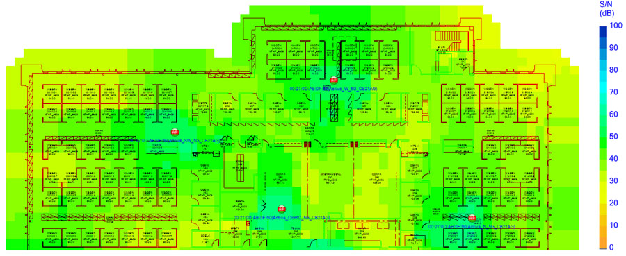
Assessing SNR by filtering out levels below, say, 25 dB of SNR should yield where VoWiFi handsets are likely to have performance problems. For an RF assessment, you should not simply look at received signal amplitude alone.
It is important to note that some WLAN clients do not properly display noise levels to WLAN analysis software. Check the client’s reporting capabilities, which may be available from the WLAN analysis vendor. In a “quiet” RF environment in the Wi-Fi frequencies, you will likely see noise levels between −95 and −100 dBm.
Trouble Spots
Upon analyzing the RF of a new network, you may have found some areas where the network needs to be augmented. Keep in mind that dynamic external factors, such as construction, furniture additions or removal, stock changes (as in a warehouse), and more can affect your design. Additionally, a network installer could have mounted an AP improperly because of carelessness or poor site survey documentation and AP mounting descriptions.
APs are sometimes mounted in strange places. Any number of variables could cause an AP to be mounted in the wrong place or way. In fact, many installation crews make mounting decisions independent of RF propagation behavior. For example, it may be difficult for an installation crew to access the ceiling in an area where the design has specified; in response, the AP may be mounted elsewhere, despite the fact that installation documentation is provided and that documentation is based on some form of predeployment site survey.
Another common issue is improper antenna orientation. If a survey was performed using an antenna pointed in one direction but installed in another, RF propagation will be different than the original design specification. Antennas may also be moved, causing improper polarization, after installation for many untold intentional or unintentional reasons.
Suffice it to say that a number of factors can come into play that will compromise a design between the time it was surveyed and specified and the time it was installed. Even if there was an error in the original design, it is best to handle it during the validation period before production use of the WLAN begins.
For designs that were based on predictive surveying methods, it is likely that there will be areas that need to be tuned for optimization. Whenever you are using predictive designs, it is likely that APs will need to be moved, added, or even removed. When adding APs after the initial installation, don’t forget to weigh the cost of changes in time, labor, and hard costs (cabling, power, etc.).
Before a new WLAN is rolled into a production state, it is always best to sweep the environment using a spectrum analyzer one last time. In new buildings where WLANs are just being installed along with other new systems purchased for the facility, there may be a source of unplanned RF interference.
If interference is found, the first challenge is identifying its sources and evaluating its potential impact on the WLAN. The second challenge is locating the source and determining an action plan to remove it if possible; if it cannot be removed, the action plan should specify how to mitigate its impact on the WLAN and design around it, as necessary.
Identifying Interference
Because we are only concerned with frequencies where 802.11 devices operate, PC-based spectrum analyzers are not only cost-effective in comparison to traditional spectrum analyzers, but they also have interference identification features that other spectrum analysis systems do not have. These features were discussed in Chapter 9, “Site Survey RF Design,” but we now need to focus on utilizing specific features of these products for the purpose of identifying and mitigating RF interference.
One of the most important tools for gauging the severity of an interference source is by looking at duty cycle measurements. As you learned in Chapter 9, duty cycle is a measurement of the amount of time the transmitter is utilizing the RF medium above a specified threshold. When interference is found, you should obtain a baseline by allowing the spectrum analyzer to collect data over a moderate period of time (this will vary with the type of interference discovered and the mission criticality of the network). After all, you’re only going to be able to quantify interference when the interferer is transmitting. It is very possible that an intermittent source of interference may be missed by simply walking through an area where the interference source is located.
Locating and Removing
After you discover interference, you can choose from many techniques, listed next, to locate the source device. Features are built into most spectrum analysis products that can filter the display to focus on a specific interference source and show a gauge of signal strength that aids location discovery.
Walking the Area With omnidirectional antennas, discovery of source devices usually means that you must walk a fairly large area in order to locate where stronger signals are present and focus more attention there. This is a time-consuming task. Sometimes the source may not even be on the floor of the building where you are walking.
Directional Antennas Directional antennas can be used as well. Keep in mind that within indoor buildings, signal reflections and other RF signal multipath may not lead you in the right location, but this is generally an accurate technique. If you decide to use a directional antenna, you may need to take signal readings from several areas (ideally spaced very far apart) to triangulate the strongest direction of the interference source. With directional antennas, lower antenna beamwidths (higher gain) provide greater location accuracy.
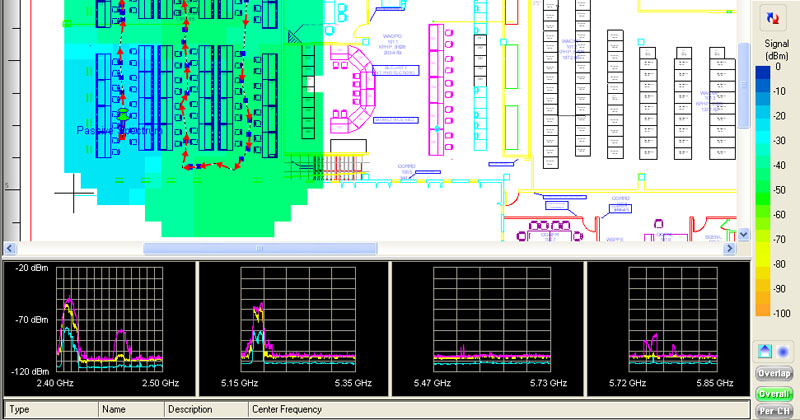
Survey Mapping Some survey mapping software packages also have spectrum analyzer integration features. That means that you can walk a facility using only a spectrum analyzer and click on a map where each data point is taken. Then, you can view the recorded data after walking the area in order to help determine where the strongest signal is coming from. This technique is shown in Figure 14.2, where spectrum analysis measurements are taken as a part of a manual site survey.
FIGURE 14.2 AirMagnet Surveyor Pro spectrum integration
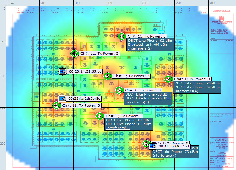
Integrated Spectrum Analysis Most enterprise infrastructure AP products are starting to incorporate spectrum analyzer features into the WLAN. This allows a WLAN controller or management server to report the strongest signal source of the RF interference. Figure 14.3 shows an integrated spectrum analysis platform that is showing multiple interferers and identifying their locations. With this technology, narrowing the search down to a single AP is an incredible gain of efficiency when you are trying to seek out interference sources.
FIGURE 14.3 Cisco interference mapping features
As you discover interference sources that cannot be removed, you also need to ask yourself if it is possible to work around the channels affected by the interference. If the source is a spread-spectrum signal, which may be transmitting across an entire frequency band, there is nothing you can do about it. However, if the device uses a specific, narrow frequency, it might be possible to change the frequency used by the interference source. In areas where it is not, perhaps the zone of impact is small enough that you can simply channel-plan around it. Yes, that means that you will have a heavier use of a few channels within that area (at least, this is true in the constrained 2.4 GHz band), but this drawback may be better than a complete denial of service (DoS) to your WLAN. If at all possible, it is usually best to simply remove the source altogether.
Once you have validated the design and implementation of all RF-related components of the WLAN (or at least have plans to resolve all known problems), you should begin to validate the other aspects of your new WLAN. These areas include wired components, 802.11 configuration parameters, and last but not least, security. Next to RF, these are the most fundamental components of WLAN design.
Wired Analysis
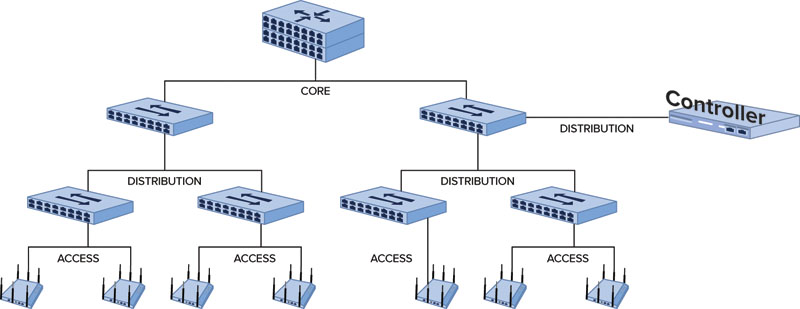
In most WLANs, APs are connected via Ethernet links. Especially in controller-based architectures, if these Ethernet links are not configured properly, the entire performance of the WLAN will suffer. For example, Figure 14.4 shows a simple network diagram of a controller-based architecture configured in a campus-based LAN. Redundancy has been removed for illustration purposes, but this diagram shows that the wireless network is not on an island. It requires tight integration with, and is dependent on, the wired network infrastructure. Each of the links between network components plays a critical part of our WLAN design validation.
FIGURE 14.4 Sample campus LAN
Link Metrics
Two important factors to consider when validating the wired network are speed and duplex, which should be familiar terms. Unfortunately, Ethernet links do not always negotiate speed and duplex settings properly. Speed in this case refers to the LAN PHY (or signaling) rate of the wired Ethernet link. Examples of common speeds are 100 Mbps, 1 Gbps, and 10 Gbps. Duplex settings refer to how transmissions are sent over that link, such as half duplex or full duplex. Half duplex will allow only one wired peer to transmit at a time while full duplex allows each side of the link to transmit simultaneously. Unfortunately, it is far too common to have mismatched speed and duplex settings between hardware devices, even from the same manufacturer. Always confirm each of these factors, at least between common congestion points in the network.
Along the same lines as speed and duplex, another important part of the validation process is interface health analysis. Each interface in an enterprise networking device will maintain individual statistics on Ethernet links. An example of interface statistics is as follows:
FastEthernet1/0/11 is up, line protocol is up (connected)
Hardware is Fast Ethernet, address is 0022.9077.e18d (bia 0022.9077.e18d)
Description: LAP in MBR
MTU 1500 bytes, BW 100000 Kbit, DLY 100 usec,
reliability 255/255, txload 1/255, rxload 1/255
Encapsulation ARPA, loopback not set
Keepalive set (10 sec)
Full-duplex, 100Mb/s, media type is 10/100BaseTX
input flow-control is off, output flow-control is unsupported
ARP type: ARPA, ARP Timeout 04:00:00
Last input 00:00:46, output 00:00:00, output hang never
Last clearing of "show interface" counters never
Input queue: 0/75/0/0 (size/max/drops/flushes); Total output drops: 0
Queueing strategy: fifo
Output queue: 0/40 (size/max)
5 minute input rate 2000 bits/sec, 2 packets/sec
5 minute output rate 3000 bits/sec, 3 packets/sec
26653941 packets input, 9734676602 bytes, 0 no buffer
Received 167656 broadcasts (0 multicasts)
0 runts, 0 giants, 0 throttles
0 input errors, 0 CRC, 0 frame, 0 overrun, 0 ignored
0 watchdog, 55882 multicast, 0 pause input
0 input packets with dribble condition detected
36014622 packets output, 28644188103 bytes, 0 underruns
0 output errors, 0 collisions, 1 interface resets
0 babbles, 0 late collision, 0 deferred
0 lost carrier, 0 no carrier, 0 PAUSE output
0 output buffer failures, 0 output buffers swapped out
You will notice that there are no interface counters for input errors, CRCs, output errors, collisions, and other statistics that indicate poor interface performance. Also notice in the beginning of this interface status output are a few bold items that can be used to verify the state of the link. In this case, the design was intended to be for 100 Mbps full duplex. This output verifies this fact.
Another common point of failure to consider in wired LANs is removable interface modules such as Gigabit Interface Connector (GBIC), Small Form-Factor Pluggable (SFP), and now SFP+ and 10 Gigabit Small Form Factor Pluggable Module (XFP) modules. It is usually more common that these modules fail before typical, built-in Ethernet switch ports. The problem is that they do not always fail completely. “Failure” could mean that they drop or corrupt some packets that traverse through them. Always confirm interface statistics thoroughly before placing the WLAN into full production.
IEEE 802.1Q Trunk Ports
When connecting two network devices together and multiple VLANs are being used, a common practice is to send traffic from multiple VLANs between network devices using 802.1Q tagging. IEEE 802.1Q tagging allows Ethernet frames from multiple VLANs to traverse a single Ethernet link while traffic is kept secure and logically separate. Ethernet frames will have a VLAN identifier, indicating their VLAN membership so the receiving device can segment the traffic back into its appropriate virtual network.
VLAN tagging can be a complex configuration process, leading to many misconfigurations. For example, let’s say you are adding 3 VLANs to an existing wired LAN design that already has 25 or more VLANs operating on it. It is a good network design principle to enable a feature called VLAN pruning to improve bandwidth across trunk links. In essence, VLAN pruning allows each switch to notify neighboring switches which VLANs it is supporting on its ports; this information allows switches to disable unnecessary VLANs on the trunk port if the peer switch doesn’t need that VLAN. Without VLAN pruning, broadcast traffic from unnecessary VLANs would cause added congestion for all trunk links in the network, thus impacting performance.
If the VLAN pruning implementation is misconfigured, or if the pruning process is done manually, adding or removing VLANs on switch ports could cause WLAN performance issues. It is particularly important to make certain that all trunk ports are not filtering out wanted VLANs, but also allow only the VLANs that are needed on each side of a trunk link.
VLAN Support and L3 Roaming
Consider a WLAN situation in which VLAN support is misconfigured on Ethernet switches. Perhaps all switch ports but one support the appropriate VLANs for wireless clients. The client associates to an AP and is placed on VLAN 54. All switches that have APs connected to them are designed to be a member of this VLAN. When the WLAN client roams onto an AP connected to a switch that cannot pass traffic for VLAN 54, all traffic for that client is dropped at the switch. No error is presented; it is simply a condition where the user of that device thinks that the network has sustained a temporary outage or they are having a problem with their client device.
Of course, it is also quite possible that the client would associate to an AP that does not support the required VLAN, in which case there will be no client service. Also, it is important to remember that some networks are designed so that clients will roam to APs that do not support the requisite VLANs. In this case, the WLAN must support a tunneling model that allows the client’s traffic to be tunneled back to the WLAN controller to be placed on the appropriate VLAN.
QoS Configuration
QoS is a big and complicated topic to address, which is why it shows up numerous times in this book. In this chapter, we will simply focus on the process of validation of QoS markings, which is important for end-to-end QoS across the wireless and wired domains. QoS isn’t supported by all devices in a consistent way. Even if a device supports QoS, it doesn’t mean that all traffic from the device will be prioritized.
For example, let’s use a QoS-capable VoWiFi phone to explore what this looks like. When a VoWiFi phone registers with its gateway, it is sending data frames that have no need to be prioritized. Therefore, the phone sends the data frames just like any normal device would send best effort data frames. Now, let’s assume a call is initiated from the phone. When a phone is instructed to dial a number, it sends this information to the voice gateway using a protocol like Session Initiation Protocol (SIP), H.323, or even a proprietary protocol. This traffic is considered call signaling traffic. Usually, a higher QoS class than data is given to this traffic. In 802.11, this is usually a UP (user priority) of 4. In 802.3 Ethernet it is a CoS (class of service) of 3. Once the call is initiated, the actual voice stream is encoded using a voice codec like G.711, G.729, or a variety of others. The voice stream is more commonly referred to as the media stream. The term “media” is used because voice isn’t the only real-time information that a communication device can send. Videoconferencing systems also send video in the media stream just as they do audio. For the media stream, the higher QoS classes are typically given, which are a UP of 6 or 7 for voice and a UP of 4 or 5 for video.
Therefore, a QoS-capable device isn’t always sending time- or bandwidth-intensive traffic that is marked for QoS. This is important to realize when you are analyzing applications and devices that support QoS.
This may seem like a lot is going on, but fortunately there is a simple way of validating both the WLAN and the LAN at the same time. The assumption here is that all of the LAN and WLAN devices actually are QoS capable and the devices honor QoS-marked traffic. With that assumption in mind, if a Wi-Fi device (such as a phone) sends QoS-marked traffic to another QoS-capable device (such as another phone) and the frame arrives to the receiving device with all of the QoS markings intact, then the WLAN and the LAN are likely configured properly.
The easiest way to do this is to use two VoWiFi phones that you know are 802.11e or WMM QoS compliant and initiate a phone call to each other while connected to a single AP. Once the call is under way, you should look for QoS markings, as shown in Figure 14.5.
FIGURE 14.5 QoS marking example to distributed system
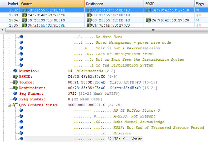
In Figure 14.5, the QoS Control Field is highlighted with the frame marking of an 802.11 frame using the G.729 codec. The frame is encrypted, so we would not have known the codec if we didn’t take the capture ourselves or were given the trace with that information provided. The next frame, #1703, is an 802.11 ACK to the previous frame. Frame #1702 was a frame originating from a phone to the distribution system (DS), as we can see just above the Duration field. We need to start with a frame originating from a device with a known marking and then follow its path back down to the receiving device. In this case, this involves two phones on the same AP. We can then see in frame #1704 that the 802.11 frame is transmitted back to the receiving device by the AP. If we look at the QoS Control Field in this frame, as shown in Figure 14.6, we see that it also has an 802.11 UP of 6.
FIGURE 14.6 QoS marking example from distributed system
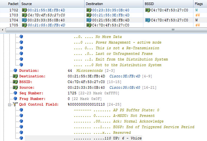
This is a rather simple method, but it means that the frame was sent from the VoWiFi device, in this case, and the AP sends it back to the other VoWiFi phone with a proper 802.11 marking. The frame has to be relayed minimally by a single AP, but in a controller-based architecture the fact is that the original frame has to be received by the AP, transmitted via the LAN to the WLAN controller, back down a tunnel to the same AP, and transmitted back to the receiving phone. In a controller-based architecture (which is what this capture was taken from), this validates that the entire network has end-to-end QoS integrity; otherwise we would have seen frame #1704 without a proper 802.11 UP marking. The UP would be 0 if something was wrong.
Next, we recommend that in this case you take one of the handsets and move to another AP on the same switch, then to another AP on another switch and any other part of the network where the network architecture might be different, and continue to validate the same information. You will not see the transmission from the original handset, but you already know it is properly marking the traffic because you verified it once. You would simply look at a frame from the same MAC address also marked from the DS with an 802.11 UP of 6. A good hint to make sure you are dealing with a voice frame is to record the frame size from the original capture and look for a frame that meets the previous criteria that also matches the same frame size.
IP and Ethernet Services
There are many network services that are used by WLANs. Although they are traditionally thought of as wired services, or they are at least services that originate on the wire, it is important that we explore the ways that WLANs use these services and depend on them:
IP Routing IP routing is usually only a wired issue in most networks. While some WLAN controllers can perform routing functions, most WLANs solely leverage the same IP routing framework as the rest of the LAN and simply add VLANs for the wireless devices.
In validating routing, you are largely looking to make certain that VLANs are routing to each other properly. When VLANs are added, it is important to make sure that you can route to all the networks that you need access to. If you find that you are not routing as you would expect, first try pinging the gateway for the network you are connected to. If you can ping the gateway, chances are that you have a routing problem. This assumes that you have not enforced any firewall rules or access control lists (ACLs) that would prevent traffic from passing.
DHCP DHCP is another area that needs to be validated. You should not only confirm that DHCP is working for WLAN clients, but also for APs that might be using DHCP. Controller-based APs are typically deployed using DHCP and may use special DHCP options as well. These options are usually to help brand-new, unconfigured APs to find a WLAN controller to join. In that case, you need to verify that DHCP options are provided back from the DHCP server that you require. One of the simplest methods to accomplish this is to do a packet capture and look for a DHCP offer in response to a DHCP request. From a packet capture utility, you can look at the DHCP offer and you can view all the DHCP options specified.
DHCP options are also used for certain WLAN clients. It is quite common to see devices request the use of DHCP options to specify a TFTP server to pull down a configuration file or other information. If your design calls for configuring these options, you need to validate the functionality of these features by using a packet capture utility once everything is deployed. In this case, you can run a packet capture utility on a laptop computer, associate to the WLAN, and then view the DHCP offer you receive after joining the WLAN.
EtherChannel One option when connecting Ethernet switches and WLAN controllers to each other is using a link aggregation protocol like EtherChannel. In simplest terms, EtherChannel takes two separate physical links and virtually bonds them together to form one aggregated link. In WLANs, ten 802.11n APs could easily saturate a single gigabit (Gb) uplink to the controller, so it may be useful to bond multiple Gb uplinks using EtherChannel. By taking two Gigabit Ethernet links and configuring them into an EtherChannel, the switch effectively has a 2 Gb uplink capacity. For example, you can configure EtherChannel in a variety of ways, and some WLAN products traditionally have not worked well with all modes. You must validate the following when using EtherChannel:
- Utilization and load balancing
- Failover
- Traffic corruption
EtherChannel functionality can be tested using multiple clients configured with load generation utilities. Send traffic in excess of a single port’s capacity across the EtherChannel link and confirm that bandwidth is greater than a single port’s capacity. You should also look at traffic counters or bandwidth statistics on the LAN switch ports before and while traffic is being sent to confirm that both links are getting their equal share of load. That is a good way of validating link utilization.
Confirming that the failover feature is working properly is fairly easy. Using the same load generation utility, simply unplug one of the links; if the failover process works properly, the link should continue to allow traffic to pass. If disconnecting one of the links drops the entire connection, that is an indication that there might be a misconfiguration or bug.
Spanning Tree Protocol (STP) Spanning Tree Protocol (STP) is a loop prevention and link failover protocol; many of those who have used it in the past would like to forget it ever existed. It has been notorious for bringing down entire LANs largely due to erroneous configuration changes. Nonetheless, it is still a commonly used protocol. It has a faster, newer cousin called Rapid Spanning Tree Protocol (RSTP), which has better failover performance than its older cousin. We will simply refer to both protocols for the remainder of this discussion simply as STP, which you can infer as STP or RSTP.
STP is still a commonly used protocol to gain link failover between LAN switches—usually from the access layer to the distribution layer or directly to the core if a distribution layer doesn’t exist, such as with smaller LANs. A common practice is to use two Ethernet links that connect two Ethernet switches with STP enabled; one of the switch ports will be blocked, which prevents the traffic loop. Should the primary link go down, the other link is enabled and the LAN stays functional.
The problem with STP is that it blocks the use of an entire Ethernet link until a failover occurs. When STP is used, the only way to prevent that is to use a proprietary method that allows the use of separate STP instances for each VLAN (PVST) or each group of VLANs (MSTP). Then, you can assign half of the VLANs to one link, where the other link is blocked for those same VLANs, and then assign the other link for the other half of the VLANs, where the first one is blocking for that set of VLANs.
As with EtherChannel, you will want to use similar methods to confirm that the STP configuration is working properly, including performing failover testing of the links to ensure that the redundancy configuration is working properly.
Power over Ethernet (PoE) Power over Ethernet (PoE) is also an item that requires validation. You might say that it is something that requires proper power budgeting within your LAN. In the design phase, you should have calculated the load that each AP will require for power; simply multiply that by the number of APs and then confirm that this total load is within the PoE supply capacity of the switch that the APs will plug into. One consideration here is that the same switch that supports APs may also support other PoE endpoints that are outside of your realm of influence. For example, perhaps the telephony team requires PoE for the wired VoIP phones. If your power budget maxes out the switch, this leaves no power capacity for the phones or for some of your APs. Needless to say, someone must ensure that the total PoE power budget is within the capabilities of the switch; you should confirm this in your design validation.
A common symptom of going over budget with PoE is when WLAN radios do not turn on. The AP might power up, but the radios do not turn on because the switch port that the APs are plugged into will not grant enough power for the AP to fully power up with functional radios. Another problem with PoE is improper negotiation. Some equipment vendors may use a slightly different PoE protocol or may have incompatibilities with PoE endpoints.
Configuration Validation
Now that some of the RF and LAN variables are out of the way, we need to turn our attention to the configuration of the WLAN equipment. There isn’t a particular order for the parameters that should be validated, nor is there a definitive list of items. As per your design, you should have specified configuration items that must be enabled, and therefore validated, in the post-validation analysis. Minimally, you should validate settings like the following:
- 802.11 authentication methods (Open, WPA, and/or WPA2)
- PHY and MCS rate settings
- VLAN assignment
- Short/long preambles (for 802.11b legacy clients)
- Protection mechanisms
- Dynamic Transmit Power Control (DTPC)
- Power saving features (DTIM and U-APSD)
- Rate limiting/traffic policing
- User policy enforcement
It is out of scope of this book to discuss the processes for validating each one of these items and their functions, but we recommend that you at least verify that each of these settings is configured and working according to the design specification.
Security Testing
Security testing is an important topic and one that can take a fair amount of time to validate. Depending on the network security policies, a variety of security aspects should be validated. It is tough to provide a list of exactly what to do for WLAN validation because every design is different. However, in the following sections we will list the broader topics and specific validation options to consider.
EAP Types
Some WLANs support multiple EAP types whereas others support only one. Regardless, you should confirm several items before configuring and testing a single WLAN client to connect to the WLAN. These include the following:
- RADIUS server is online and functioning.
- All APs or WLAN controllers are added to the RADIUS server as RADIUS clients.
- RADIUS servers are configured on the APs or WLAN controllers.
- RADIUS servers and APs or WLAN controllers are using the correct UDP ports and shared secret.
- RADIUS server is configured to support the EAP type(s) that WLAN clients will use. Also, ensure that only the EAP types you want to support are enabled and nothing more.
- 802.1X is enabled on the APs or WLAN controllers for each of the SSIDs that will use 802.1X/EAP.
- Clients are properly configured with proper EAP types and related settings.
These items should always be validated before attempting to connect any WLAN client. If you have validated each of these items and a WLAN client still won’t connect using one of the allowed EAP types, you should refer to debug logs, system logs, vendor-specific messages, or other similar troubleshooting options provided by the equipment vendors in order to determine your next steps.
Authentication and Accounting
When using 802.1X/EAP, confirm that authentication is being logged properly on the RADIUS servers along with the associated accounting information for each WLAN client. Most WLAN equipment vendors allow for configuration of authentication servers separate from accounting servers. It is important to verify that both are functioning as expected.
You should also configure a log file or database backup or archiving scheme for these log files. Some organizations require retention of these log files for a certain period of time.
Encryption
Whenever a WLAN is deployed, 802.11 encryption should be a requirement. Perhaps the only exception would be for guest networks. However, some organizations even use a WPA PSK for their guest networks as a deterrent to keep neighbors from using the guest WLAN.
To determine if encryption is being used properly, use a WLAN packet capture utility. Configure the packet capture software to capture data frames that are supposed to be encrypted and validate that no upper layer data is visible. You could also confirm this by checking specific information elements and fields in certain management fields. For more information on those details, refer to the CWAP Certified Wireless Analysis Professional Official Study Guide by David Coleman (Sybex, 2011).
Wired encryption is also an option with some enterprise equipment manufacturers. For encryption protocols supported over the wire, such as for VPNs, tunneling to a controller, or tunneling between APs, a simple wired Ethernet capture of the traffic will verify data privacy as well.
Device Management
Once a WLAN is configured and is ready to be placed into operation, management capabilities should be locked down with an appropriate accounting trail. You have a variety of factors to consider here, including VLAN segmentation, firewalls, ACLs, administration credentials and privileges, and access protocols.
First, management interfaces of WLAN equipment should only be placed on specific firewalled or ACL’d network segments. This prevents infrastructure equipment from even seeing any requests to manage the equipment from unauthorized users or subnets.
Next, login authentication methods may be used, such as a RADIUS server, a built-in database, or a different user authorization management system such as TACACS+. The benefit of an authorization management system is that individual user logins can be allowed or denied the use of certain configuration commands with the WLAN infrastructure devices. In other words, your organization may require layered administrative access in which different members of the IT team are granted scalar configuration and monitoring permission. The same system also logs all of the activities users perform in an accounting database. These accounting databases can be helpful to use for security forensic purposes. Needless to say, all default manufacturer credentials need to be changed or deleted.
Protocols used for management may include Telnet, SSH, HTTP, HTTPS, SNMP, and more. Telnet and HTTP are protocols that do not use encryption. When a user logs in via one of these protocols, the username and password can be seen in clear text if the packets are captured. For this reason, these protocols should be disabled. As an alternative, SSH or HTTPS should be used; both offer strong encryption.
SNMP is often enabled on infrastructure equipment by default. Worse yet is that the SNMP strings and login information are parameters that can be easily obtained from a user manual that is public domain. All default logins and SNMP community strings should be changed or deleted. Some equipment vendors allow the use of ACLs that prevent any device from performing SNMP requests to an infrastructure device. Where possible, newer versions of SNMP, such as v3, should be implemented for best security practices.
Traffic Filtering
A variety of features fall into the traffic filtering category. Some equipment vendors offer more features than others, so this may be a quick exercise depending on the equipment manufacturer and/or the configuration complexity of your WLAN design. Yet whatever equipment you are using, there are a few things that you should confirm in a WLAN post-validation effort, assuming these options are present.
Some WLANs can block some or all peer-to-peer traffic. Sometimes this blocking is a good idea, but in other instances, it can be a serious problem depending on the applications being used. For instance, a voice SSID using peer-to-peer traffic blocking would be disastrous. However, we usually recommend enabling this feature for a guest WLAN. Always validate this feature to make sure it is configured properly.
As you test devices for basic connectivity, watch for firewall software that is enabled on PCs. If you attempt to ping another WLAN device from a different WLAN device, the receiving device may have firewall software enabled and might block all ICMP traffic, thus preventing an ICMP response. Confirm that firewall software is not enabled on the test devices.
Another form of traffic filtering is URL filtering. This form of traffic filtering is commonly used in enterprise and guest networks. Many enterprises filter out the use of social networking sites, media streaming sites, and other web destinations known to host malware, illegal content, or other illicit material. For guest networks, the worst thing a company needs is to provide guest access to somebody viewing inappropriate material and another guest user to witness it. This is the reason many organizations use some form of URL and content filtering.
There are many other types of filters, such as time-of-day restrictions for certain users and rate control filtering. It is a good practice to test such mechanisms by attempting to violate them.
Rogue Detection
Rogue detection and mitigation features are becoming more sophisticated for WLAN equipment, and some of these features may be enabled by default. Depending on your organization’s security policy, you may have a simple and minor detection policy, or you may have a sophisticated one. In either case, it is important to test and confirm that detection, reporting, and mitigation features are all working as desired. Test this capability by installing a rogue AP and confirming that an alarm is triggered and logged, or a report is generated, or possibly that the AP responds with appropriate active containment measures. Each policy will differ, but the same principles apply across all networks. Make sure the features are working before you set them loose and trust that they are providing the desired protection.
Client Device Validation
Once you know the infrastructure design is validated at a fundamental level, you must investigate the other end of the RF link—clients. This step needs to be done before you proceed any further in the validation process because if the client devices are not configured properly or there is an unforeseen incompatibility, the subsequent validation phases would need to be performed all over again.
Configuration parameters selected between infrastructure components and client devices must be in parity. If devices are not in parity, you can not only expect poor performance, but you may also experience more severe problems that affect reliability as a whole. For example, a client device that is not configured to use the right frequency bands or 802.11 parameters may not associate to the WLAN how you intend. If your network uses 802.11n at 5 GHz, you must ensure that you are enabling 802.11n and that you have also enabled 5 GHz. All client driver and supplicant settings need to be validated in this step.
Using a survey client equipped with special analysis software can only provide one perspective of the WLAN installation. A survey client is usually a specific laptop and radio card that the IT staff or an outside vendor uses where the survey analysis software is exclusively licensed to. The perspective from these devices is nearly always not quite the same picture that your actual client devices will see. More specifically, special survey clients do not tell you how the actual devices the network must support will actually behave. Different WLAN radio cards, antennas, driver software, configuration parameters and many other factors influence how different devices behave differently. Therefore, you must perform a validation using a representative sample of the actual supported WLAN devices. This may seem logical, but this is usually the most underperformed design validation step.
Ideally, your design should have already dictated specific client driver versions that were tested to be compatible with WLAN infrastructure firmware that you have deployed at this stage. WLAN client drivers may have substantial compatibility and performance issues with certain infrastructure software versions. Therefore, at this stage, you want to check to see what drivers your clients have deployed in addition to configuration parameters.
One product used to perform client testing is WaveDeploy from VeriWave. WaveDeploy provides the ability to perform a battery of tests using the actual client devices configured for your network. WaveDeploy places a small software agent on each client device you would like to test. The software agent then checks in with a central software console that usually resides on an Ethernet network. The central software console can then command each client device to perform a specific test plan. This is done by the test conductor clicking on a map location where client devices are physically located. If several client devices are used, the tests are performed serially, which may take some time to execute depending on the configured test plan. The devices are then moved to a new location, and this process is repeated. The final result it a series of heatmaps that show how each client device performed at each location. This not only includes RF coverage information, but also throughput in uplink and downlink with a variety of application protocols, MOS score for voice clients, latency, and more. This process can allow for fine tuning of infrastructure and client device parameters by making software and/or configuration tweaks and executing the process again.
Another product that has been used to test network devices is IxChariot from Ixia. IxChariot is more suited for performance and application testing on Ethernet networks rather than RF and 802.11 testing, but nonetheless provides a great deal of valuable data to validate against.
When recording results from client devices, you need to record at least the following information along with the test data set:
- WLAN client device make and model
- Make and model of the WLAN radio card
- Antenna details if external antennas were used
- WLAN driver or device firmware versions
- Complete documentation of all client driver, supplicant, and any configuration parameter that will affect radio behavior
Depending on how the test is performed, other information may also be required, but this list should provide a valuable baseline. It is also assumed that you have already captured a snapshot of the infrastructure equipment and infrastructure RF state prior to client testing. If you do not have both sets of information, interpreting the data is left to a great deal of guess work.
We recommend that you perform some form of frame and channel analysis during a post-validation. It can be a highly definitive way of capturing important metrics that indicate a properly functioning WLAN.
An 802.11 frame capture utility will need to be used for these purposes. While Linux has a few basic utilities to perform some analysis, most of the Windows utilities are more sophisticated. Some are free (though you must purchase supported adapters), and others come in a range of cost. If they can be justified for your organization, these tools can be well worth the money. Some popular examples include Wireshark, CommView for WiFi, WildPackets’ OmniPeek, and AirMagnet Analyzer.
As you analyze your network at Layer 2, there are a lot of details. Let’s look at some of the most important areas to focus on at this stage of the deployment.
Important Metrics
Some analysis tools report so much data that it can be confusing. Certain metrics provide the best insight into the network’s health, and we will focus on these in the following sections. Since most networks use encryption (which obfuscates Layers 3–7), frame analysis is primarily done at Layer 2. We will focus on networks that use encryption because that is (and should be) the most common method.
Retransmissions
In RF communications, especially ones that use unlicensed frequencies, retransmissions are simply a fact of life. You’ll never see a network completely rid of them. Whenever a frame isn’t heard or cannot be decoded as transmitted, the frame isn’t acknowledged (ACK’d) by the receiver (assuming some acknowledgment is expected). This informs the transmitter that it must retransmit the frame.
Retransmissions in WLANs are the frames that are picked up by a protocol analyzer that have the retry bit set to 1 in the 802.11 frame header. A good general rule of thumb in large WLAN deployments is for retransmissions to be approximately 5 percent or less of all of the frames transmitted. More than 10 percent retransmissions is usually a sign that the network is experiencing poor RF performance. Also, it is important to realize that as higher signaling rates are utilized on the WLAN and overall capacity and throughput increases for a cell (such as with 802.11n), retransmissions may actually increase, and this is normal. With more PHY rates, the more rate shifting will occur as the RF link between the client and AP changes. Clients and APs usually change PHY rates after they have to retransmit frames. With more rate shifting, there should be more retransmissions by definition. There is still a NET gain because the time it takes to transmit the same information at a higher PHY rate is less.
Keep in mind that if a single device is communicating, and it has a very low signal or is not sending much traffic, the data sampling may not be representative of real-world conditions. It is always best to have clients deployed in their intended use case and have people use the devices as they would normally be used. A data sampling of that type should be the only type used for this analysis.
CRC Errors
When 802.11 frames are received by a frame analyzer but cannot be properly decoded for one reason or another (usually low SNR or interference), this is usually characterized as a CRC error. A valid CRC error count is similar to the retry count in its indication of network health, but it is important to understand the difference. That is, retries indicate that the intended receiver did not correctly receive a frame and that the transmitter resent it. CRC errors only indicate that the network analyzer did not correctly receive a frame. This difference cannot be understated. The significance here is that a protocol analyzer typically uses a client adapter and antenna, which are typically inferior to AP radios and antennas. Similarly, the receiving capabilities of the analyzer software are dependent on location. In other words, you are collecting network statistics at a point in space, and that point in space may not be representative of the entire network. Weigh the CRC error count as a performance metric with those considerations in mind. When possible, obtain the CRC error count from the WLAN infrastructure platform itself, and this will give you a better sense of performance.
It is important to understand that some clients will be communicating with the AP at high PHY rates. The ability for those devices to use high PHY rates is a function of the RF quality between them. If your analyzer is not in the same vicinity to hear the communication at the same RF levels, your analyzer may not be able to understand the full conversation. For example, if you are analyzing communications between client(s) and an AP that are on the other side of an RF coverage cell, there is a strong chance you will not pick up all of the traffic. It is quite common that your protocol analyzer will report the frames it did not fully receive intact as CRC frames. The preambles sent at the beginning of each 802.11 frame are always done so at a low PHY rate and the rest of the frame is usually sent at a higher PHY rate (in most circumstances). Therefore, your analyzer’s radio can usually decipher that a frame is being transmitted (because it heard the preamble), but it cannot decipher the payload sent using a higher order modulation of a high PHY rate. Keep this in mind when reporting on CRC errors.
Similarly, keep in mind that not all client adapter drivers are equal. Some drivers filter out traffic so that it is not reported to the operating system (and therefore the analyzer) if signal levels are really low. It is a best practice to use drivers that are designed specifically for the analysis software.
CCA Congestion
Wireless medium contention practices can also be helpful for indicating when an 802.11 network becomes overloaded. IEEE 802.11 is, by design, a listen-before-talk protocol. If the wireless medium is busy and the device needs to transmit, it will wait to use the medium until the medium is idle. This process is called clear channel assessment (CCA), and a saturated RF medium is often referred to as CCA congestion. Some infrastructure devices report this information in statistic counters, which provides incredible insight to the inner workings of the AP in the RF environment.
One interesting thing to observe in large WLAN deployments is variance in this statistic between APs. Areas where there is a high amount of busy time can indicate areas of RF interference and/or very high traffic usage that might warrant further investigation.
Highly Variable RF Signals
In some network deployments, a dynamic RF environment with excess multipath can cause highly variable signal amplitude at the location of a specific receiver. If the variance in signal amplitude of successive signals at a receiver is too large, it might be an indicator that too much multipath is present or possibly that diversity isn’t working properly on the client or AP device. As you measure signal strength, a range of 10 dB isn’t uncommon. However, greater variations in devices with simple diversity may represent an issue with excess multipath. 802.11n MIMO can utilize this phenomenon for signal processing gains, but legacy 802.11a/b/g devices cannot cope as well with multipath.
If you are experiencing this issue with 802.11n, you may have an issue with MIMO diversity. If you see this problem with 802.11a/b/g, try moving a few inches or so and repeat the analysis. You would be surprised how much difference there can be in RF sampling with even small location changes. If the same problem is still being seen, you should investigate if antenna diversity is working properly, if the device supports it.
There have been several installations that have benefited from AP relocation even to within several feet from the original location. This issue is even more critical for PTP or PTMP RF links.
Channel Performance
Ultimately, much of the performance of a WLAN depends on available channel capacity. When channel capacity is used up, there is no opportunity for a performance increase. We have already discussed in this book the effect that low PHY rates can cause on large WLAN deployments. Low PHY rates can be decoded much further than higher PHY rates. To make matters worse, an 802.11 frame sent at a low PHY rate occupies the wireless medium much longer than the same frame transmitted at a higher PHY rate. Effectively, channel capacity is reduced simply from 802.11 management frame overhead sent at low PHY rates, even when the network is not transferring data traffic.
To prevent this from crippling the network, PHY rates should be appropriately configured in the WLAN based on a proper RF site survey. Usually, even a data grade network with APs spaced further apart than WLANs providing real-time services should normally not need PHY rates lower than 11 Mbps. There are cases where stations can benefit from lower rates, depending on where they are connecting from, but in general, PHY rates lower than 11 Mbps will do more harm than good in the vast majority of large WLAN deployments.
To measure channel performance, use a professional WLAN analyzer. One that performs exceptionally well in this use case is AirMagnet WiFi Analyzer, shown in Figure 14.7.
FIGURE 14.7 AirMagnet WiFi Analyzer channel analysis
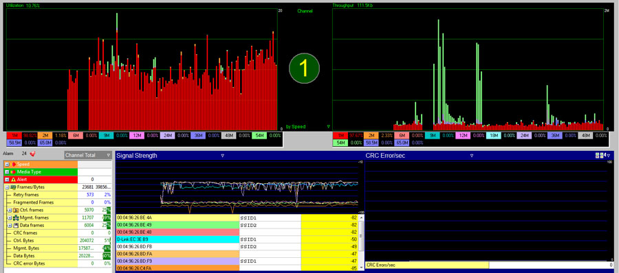
The graphs in Figure 14.7 show channel utilization (top left) and bandwidth (top right). On the left, not only do you see how high the utilization is for each measurement interval, but you also see a breakdown of the PHY rates that contributed to that channel utilization. This is a powerful graphic because it correlates transmitted data in the same interval and allows you to see the inversely proportional effect that lower PHY rates have on performance and channel utilization. You can also see that when high PHY rates are in use, a substantial amount of traffic can be sent with low channel utilization.
The AirMagnet WiFi Analyzer is notoriously colorful. Unfortunately, including screenshots that are printed in grayscale does not do justice to the capabilities of this platform. On a computer monitor, this data is very useful and tangible for analysis and design experts.
Today’s wireless networks are increasingly supporting mobile devices and applications. For that reason, it is important to validate client roaming functionality before turning the network loose.
An important fact about the 802.11 protocol is that clients make the decision when and where to roam. Because clients are the ones that are mobile, this makes sense. The problem is that client roaming algorithms are all different, meaning each client device (driver, really) behaves differently. Chapter 2, “Designing for Client Devices and Applications,” goes into great detail about client roaming issues and how to properly design for them. This section will cover how to assess client roaming behavior as well as the impact that 802.1X/EAP security can play in the roaming process.
Assessing Client Roaming
The IEEE 802.11 standard does not currently specify any details about when and why clients should roam to another AP. This is up to client device manufacturers to implement as they see fit. Because clients make the decision to roam and there are a variety of WLAN chipsets, driver versions—along with configuration options—control roaming processes. For that reason, each client type should be assessed independently.
The method for doing this can be as minimal or extensive as your organization requires. It can be as simple as walking around the WLAN deployment with the client device running an application and gauging performance purely from an end-user perspective. This method is certainly sufficient for some situations, but if you would like to know more information about device behavior, you might also run a program, if available on the client device, that displays connection status and performance metrics. Specifically, we are looking for RF metrics like RSSI and/or SNR metrics, and ideally application metrics as well, such as errors, retries, round-trip delay and jitter, and loss. Another important piece of information is the MAC address of the AP that the device is connected to. This information is helpful in determining the location and RF signal levels when devices will roam.
If you have designed your network properly, you should have cell sizes that do not have too much co-channel interference. RF cells should have some level of overlapping coverage to facilitate a seamless roaming experience without too much signal degradation, but not so much coverage that you still have high signal strength while standing underneath an adjacent AP. This is a sign that the APs are placed too closely together or perhaps that transmit power is set too high. Usually it is the former because if transmit power is set too high—implying that transmit power on the AP is higher than what is capable from the client device—the uplink transmissions from the client device may not be heard by the AP with the same reliability as downlink transmissions from the AP. In this case, the client device would look to roam when traffic conditions degrade beyond a certain threshold. Keep in mind that not all clients will do so because some client vendors simply key the roaming process from RF signal levels alone. That is not optimal.
Roaming between frequency bands may also be an important requirement for your WLAN. The reasons for this vary, but sometimes it is solely due to being resilient to RF interference on one band. Should a device roam between frequency bands, we need to observe that the roaming process is not disruptive and the client device doesn’t disconnect in such a way that end users will notice the effect. This also means that the infrastructure does not place the client on a new VLAN (or if it does, it uses tunneling to maintain IP connectivity) and the mobility and authentication state is kept seamless during a roam between bands.
802.1X/EAP Roaming Performance
There are several items to examine when analyzing 802.1X/EAP performance. First, an important statistic to measure is the time it takes for initial association and authentication using the 802.1X/EAP protocol(s) that will be used on the WLAN. This includes the total time to perform a full authentication beginning from the initial 802.11 association request and ending with the WPA four-way handshake completion. Ideally, we would like it to be 250 ms or less in good RF conditions. If the RADIUS server is located over a WAN link, this will certainly add time to the authentication process. Keep in mind that in poor RF conditions, retransmissions and added latency from slower PHY rates are likely to increase this time substantially. First test the initial authentication in good RF conditions.
By definition, the authentication time for the first authentication cannot be using a previously authenticated session. If it is, try fully rebooting the WLAN client or forcing a client off the AP or WLAN controller using an appropriate command based on the equipment vendor’s product. Usually, what you want to see is a full 802.1X/EAP authentication using a strong EAP type.
Next, you want to measure roam times to other APs. When 802.1X/EAP is run with fast secure roaming (FSR), opportunistic key caching (OKC), 802.11r Fast BSS Transition (FT), or vendor proprietary features, you should see substantial improvement on roam times. WLAN controllers can track clients using the same credentials when roaming between APs that are under its control. Even when you are using the strongest of EAP types, roam times can be as little as 20 ms. Generally speaking, roam times less than 50 ms are considered very good with 802.1X/EAP; in fact, that’s the target metric used for the IEEE 802.11r standard.
Performing a roaming analysis is challenging using a single WLAN radio with a WLAN capture utility. If you do not have the ability to perform a multichannel capture using multiple WLAN adapters on your analyzer, you can lock in your analyzer to the RF channel of an adjacent cell to which you will roam the client device you are analyzing. Then, associate to an AP and walk toward the AP whose channel you configured your analyzer to capture and you should capture a full roaming event beginning with the reassociation request.
Channel Support
It is critically important to ensure that client devices support all the channels that are used by the WLAN infrastructure. Years ago, the 5 GHz UNII bands were expanded to include more channels in a frequency range called the UNII 2 extended (2e) band. Almost all 5 GHz–capable client devices that are several years old were only certified and designed to support the 5 GHz UNII 1, 2, and 3 bands. Therefore, if you configure the WLAN infrastructure to support a UNII 2e channel you could be creating dead spots in your network for some WLAN clients.
When you’re buying a new sports car, it’s easy to feel like a teenager again as you drive off the lot, thinking “What can this thing really do?” Testing a WLAN deployment can be a similar experience. You’ve spent an incredible amount of time and money planning, installing, and configuring your new WLAN. Now, wouldn’t you like to know what kind of maximum speeds and client density numbers can be expected?
While there is more than one method to accomplish just about any type of test, this section will provide methods and criteria for performing a thorough load and performance evaluation process. You may ultimately decide to implement your own method based on your customer or deployment environment, but the concepts in the following areas will still apply.
Throughput
Performance doesn’t always boil down to throughput, but it is important to know what bandwidth limitations exist. If performance is really poor, it might point to another problem somewhere in the WLAN infrastructure, the clients, the wired infrastructure, or elsewhere.
As wireless technology is becoming increasingly faster, it can become harder to generate enough load from a single client for an adequate throughput test. Therefore, several clients may need to be used. In fact, it is a far more realistic test to perform load testing using several WLAN clients. This approach allows for completely separate 802.11 state machines, (ideally) different RF conditions, different PHY rates, and medium contention processes to be evaluated in the test.
Throughput Performance Checklist
When you’re performing throughput testing, the following is a good checklist of areas to consider:
Different Clients It’s best to understand the impact of mixing legacy and 802.11n adapters. You should also understand the impact of mixing different types of chipsets and even software versions that you will have in production. However, keep in mind that you are validating your network for the real world, so attempt to mimic your native client population as closely as possible.
RF Conditions Place clients in different physical locations, testing varying RF signal qualities. Do not place clients in poorer conditions than what you would encounter in your production environment.
PHY Rates Ensure the proper PHY rates are enabled before testing, confirming that the lowest basic rate is properly set.
Bands Run tests with clients on different bands. This information can help you determine if you want to force specific clients to use only a specific band. Not all clients perform equally on different bands for a variety of reasons.
Protocols Certain application protocols have more overhead than others, so test using different types of protocols, minimally to include TCP and UDP.
Applications
When you’re performing network performance tests, several free and fee-based utilities are available. We have listed a few popular ones with enough information to get you started using them quickly.
iPerf
iPerf is arguably one of the most common command line-based network performance testing applications available. iPerf is a free, open source software utility. Many first-time users complain that they are unable to achieve the performance results they were seeking. jPerf is a derivative from iPerf that adds a graphical UI, making some functions easier to use.
You can download iPerf at http://sourceforge.net/projects/iperf/.
The following syntax should produce good results over 802.11 wireless networks:
Measuring TCP Throughput Run the following command on the server with a 256 k TCP window size:
Iperf -s -w 256k
Run the following command on the client with six simultaneous client threads, also with a 256 k TCP window size, and perform bidirectional tests individually for a total time of 60 seconds:
Iperf -c <server IP address> -P 6 -w 256k -r -t 60
Measuring UDP Throughput Run the following command on the server with a 56 k buffer length:
Iperf -s -u -l 56k
Run the following command on the client with a 56 k buffer length, 50 Mbps of bandwidth, and six simultaneous client threads:
Iperf -c <server IP address> -u -b 50M -l 56k -P 6
nuttcp
nuttcp is a command line-based platform for TCP or UDP network performance testing and is a free, open source utility.
You can download nuttcp at http://www.lcp.nrl.navy.mil/nuttcp/.
The preferred setup for nuttcp is to configure one host to run in server mode (-S) and a second host to either transmit or receive data from the server by specifying a -t or -r, respectively. One of the nice features of nuttcp is the amount of options it provides. You can specify details such as QoS values, window sizes, frame sizes, and others.
The following syntax should produce good results over 802.11 wireless networks:
Measuring TCP Throughput Run the following command on the server:
nuttcp -S
Run the following command on the client to receive traffic, reporting data in one-second intervals, with a socket buffer window size to 8 MB:
nuttcp -r -i1 -w8m <server IP address>
Measuring UDP Throughput Run the following command on the server:
nuttcp -S
Run the following command on the client to transmit traffic using UDP, reporting data in one-second intervals:
nuttcp -t -u -i1 -l512 <server IP address>
IxChariot by Ixia
IxChariot is a test tool for simulating real-world applications to predict device and system performance under realistic load conditions. The IxChariot product family offers thorough network performance assessment and device testing by simulating hundreds of protocols across thousands of network endpoints. IxChariot lets you confidently assess the performance characteristics of any application running on wired and wireless networks. IxChariot is a fee-based software product.
Find information on IxChariot at www.ixchariot.com.
WaveDeploy by VeriWave
WaveDeploy is a site assessment and readiness solution for IEEE 802.11a/b/g/n networks. It provides deep insight into the behavior of live networks while consuming a minimal amount of time to conduct a survey. WaveDeploy is a panoramic solution that offers passive, active, and mobility measurements by client during a single pass through the surveyed facility. It delivers true end-user Quality of Experience (QoE) measurements based on the nature and behavior of client devices and applications running on these devices as well as the interaction between those devices and the network infrastructure.
WaveDeploy Basic and other information on WaveDeploy products can be found at www.wavedeploy.com.
WaveDeploy offers a free version, called WaveDeploy Basic, which provides TCP Downstream, RF Signal, and Co-Channel Interference heat maps. VeriWave also offers a Pro and Expert version with expanded features.
Jitter and Latency
The concepts of jitter and latency have been discussed at various places in this book and should be well understood at this point, so we will not review them again. Yet the question of how to measure these metrics still remains. These are important metrics for latency-sensitive applications, so you should validate them during your WLAN assessment.
Measuring Latency
It is usually more important (and easy) to measure latency for round-trip times than for one-way times. If an 802.11 frame is sent to a particular destination, measuring the time it takes to receive a response from the destination device is the key metric because it mimics the end-user experience more accurately.
Basic latency is usually measured by sending a ping packet because the receiving device doesn’t perform any processing on the packet, so there is no processing delay. This makes measuring latency more accurate. However, because 802.11 WLANs are encrypted, this is hard to measure with a protocol analyzer. Therefore, it is usually best to perform from the actual devices operating on the WLAN. Also remember that ICMP will not be prioritized with QoS, so this is a somewhat barbaric measurement of latency. For truer measurements, you will have to implement a software test solution that performs this measurement with two endpoints.
It is quite common to see some 802.11 devices that have more latency than others when using ping, for example, for measuring latency. The root cause of this added latency may be the power save settings on the client devices themselves. Therefore, you should test with these settings on and off if you are experiencing higher-than-expected delays and most certainly if it is only with some devices versus others. If you do not see any differences between devices, the issues likely are network related. When using a QoS-based method of testing latency, you may find that high latency points back to a QoS confirmation problem.
Measuring Jitter
Jitter is a little trickier to analyze. To measure jitter, you must have a constant stream of traffic with frames of similar size transmitted at regular intervals. Without that, transmission times from the source itself are variable and will always result in variable timing differences between responses. Therefore, only real-time protocols like voice or video media streams are the focus of jitter measurements.
Many protocol analyzers offer “voice” versions that are usually upgraded versions of standard or professional offerings. In these products, a variety of tools are available for performing this analysis. Unfortunately, in the WLAN industry, they don’t offer as much value. The reason is because nearly all of the voice and video traffic that is sent on a WLAN is encrypted. Sometimes this encryption is in very weak forms that can allow someone to use a protocol analyzer to decrypt the traffic if the encryption key is known (such as with WEP and WPA-PSK). However, this is not possible with 802.1X with strong EAP types. Therefore, you have to dig a bit deeper to ascertain which set of frames you captured are actual voice or video frames that need to be analyzed for jitter.
Some voice and video devices themselves can report jitter. It makes sense to capture this from the devices themselves because they certainly know which traffic to rule out of measurement calculations. The problem arises when the devices report a high degree of jitter and you are then faced with figuring out the root cause. Devices simply report the presence of jitter. The analysis involved in this process is beyond the scope of a design book and better left to an analysis discussion. This topic is addressed in the CWAP Certified Wireless Analysis Professional Official Study Guide by David Coleman (Sybex, 2011). Beyond using the actual 802.11 client devices themselves, using one of the voice analysis products on the market can assist with this process. The other most common root cause is wireless medium contention due to high channel utilization, lack of end-to-end QoS integrity, or the traversal of a large number of network hops by traffic.
We have focused most of this chapter on analyzing OSI Layers 1 and 2 because unless those two layers are healthy, the entire foundation of the network is on rocky footing. However, this is not enough; we also recommend that you test primary applications that will operate over the WLAN. These may include a wide variety of applications such as general email and web browsing applications, guest access features, and many others.
You will hear the term Quality of Experience (QoE) used when referring to application performance. Effectively, QoE is a term used to quantify the end-user experience of the person using an application on the WLAN. In the next section, we will discuss some basic administrative considerations for network application usage as well as for guest networks.
General Data
In the general data application category, we are generally talking about non-real-time applications, like email, web browsing, and others. Real-time applications require their own set of tests that will vary depending on the application requirements and perhaps the application manufacturer. Since we have already covered many of the topics relating to performance metrics, we will not go into more detail for real-time applications.
When you’re performing tests for general data applications, it is important to perform these tests using the devices that will be deployed over the WLAN. Use credentials and security authorization privileges that general users will be using. This will help you validate that not only the 802.11 security authentication is performing as expected, but that the entire end-user experience is satisfactory.
Often, administrators test their own laptops and user accounts on any type of network and subsequently feel that everything is working as expected. They often forget that other users do not have the same level of elevated authorization privileges or that the device they are testing may have been altered in other ways. Administrators usually tinker with their devices and have increased security privileges that common users don’t have. Testing the lowest common denominator in this fashion will help validate various firewall policies and other features as well.
In short, perform testing using devices and accounts of end users in order to gauge real-world application performance. This may even mean that several different types of devices may need to be tested with different user credentials, depending on your design.
Guest
Guest networks work by performing some sophisticated interception and processing of client device traffic. Guest networks have several areas that can go awry, such as the following:
- How guest users are filtered and walled off prior to authentication
- What services may be available immediately
- How browsers are redirected for acceptance of usage terms
- How the entire guest authentication application operates
Guest networks are a combination of OSI Layer 2 interception, protocol and service filtering, and browser-based applications; each portion needs to be tested thoroughly.
When providing wireless guest access, usually the first requirement is to keep guest users from accessing important network resources that only authorized users should access. Therefore, the first test you should perform is to ensure that all types of traffic, including non-web-based traffic, cannot reach any internal network resources. If resources can be reached, there is a problem either in the design or implementation of the guest solution.
It’s also important to perform valid and nonvalid authentication of the guest application from a variety of end-user devices. These include laptops, mobile phones with 802.11 radios, and personal tablet devices. Also, test devices with different operating systems, browser types and versions, and WLAN adapters.
Common features used in guest network applications include rate limiting and time-based deauthentication. You should test each of these processes in turn by attempting to generate large traffic loads and then by attempting to remain connected beyond the time restriction value. Ensure that clients are properly rate and time limited. Of course, you should also test any other features you are implementing, such as secure captive portal authentication, collection of payment for charged services, and any others.
Failover and Redundancy Testing
What happens when a component of your WLAN design fails or goes offline? The answer to that question is important, and it depends on your redundancy and failover strategy. This is one of the most important facets of all modern networking in business environments, as most networks are mission critical for business functions. It is best to quantify the outcome of failure events before a WLAN is placed into production, which includes documenting the results for future reference. That is especially true if you are not the one who will be operating the WLAN on a day-to-day basis. In the next section, we will discuss many aspects to the redundancy and failover strategy.
Network Switch Failover APs are usually powered by PoE sourced from a network switch. This means that in the event of a total switch failure the APs will power down and RF coverage, along with all wireless service, will be lost. Some organizations choose to install multiple switches in equipment closets and alternate placement of APs between different switches. This helps minimize the impact of a switch failure and prevents huge sections of RF coverage from being lost.
Router Failure In the event of a router failure, most network designs incorporate some form of redundancy. Because routing is such a critical function and typically performed at the distribution or core of a LAN, if the device failed without any redundancy then it can not only take out the entire WLAN but the entire LAN as well. For this reason, redundant routers are usually deployed using Hot Standby Router Protocol (HSRP), Virtual Router Redundancy Protocol (VRRP), or other mechanisms to perform automatic failover in the event of a single router failure. Router failover testing should also be performed for a new WLAN install, and it is smart to perform some testing on a regular basis—at least annually.
WLAN Controllers WLAN controllers present a critical failure point in many WLAN designs. Sometimes hundreds of APs can be serviced from a single WLAN controller, and losing one can be a catastrophic event if redundancy is not accounted for. WLAN controllers should be deployed with some level of failover. Perform several types of failure testing with WLAN controllers before going live with a new WLAN deployment. Test Ethernet link failure and then perform complete controller failover testing. Depending on the equipment vendor, there may be specific features that govern the behavior of devices in the event of certain failure events, and this is also a good time to test them outside a lab environment.
The severity of a WLAN controller failure depends on the architectural model in use. If all data is forwarded through the controller, a failure is catastrophic if a backup is not in place. For distributed forwarding, the controller may be providing some authentication and Radio Resource Management (RRM) services, so the immediate failover is slightly less significant. In either case, you should know what services are lost in the event of a controller failure.
Link Failures In the earlier section “Wired Analysis,” we discussed link failures, but it is worth mentioning again. Regardless of whether you’re using EtherChannel, test Ethernet link failure and bring the Ethernet link back online to ensure the network will recover from a failure. If you’re using EtherChannel, test each link of the EtherChannel configuration, and when you restore the link, full service should commence. Alternatively, you can use other forms of link redundancy that is vendor proprietary.
RADIUS Failover Testing RADIUS failover testing is an important core component of a WLAN that should be well tested. Failover can happen as a result of various reasons. Failover decisions are controlled by the authenticator role in the 802.1X process. You can’t expect the reasons for a RADIUS failover to always be what you expect. Even once a failover happens, does the authenticator fail back to the RADIUS server that you expect? It isn’t sufficient to only cause a failover and test whether failover properly occurs; you must also test whether the authenticator will fall back to the originally designated authentication server if that is what your design intends in the event that the primary configured server is restored to a normal operating state.
DHCP Failure DHCP failure can cause disastrous effects to network operations. Nearly all WLAN client devices used in the majority of network designs rely on DHCP. If DHCP isn’t fully reliable, client connectivity will be stopped short, preventing any real use of network services. It isn’t just important to test the affected client devices that use the WLAN—you must also test APs that operate using DHCP. APs that use DHCP are typically controller-based APs, but some network designs incorporate DHCP reservation for all network devices in order to allow for easier network address management from a centralized location. IP helper commands are also administered on routers that redirect DHCP requests to these central servers. Ensuring that backup addresses are configured and properly redirecting traffic is also important.
Before we complete this chapter, it is important to wrap up all the technical discussion with a business reminder. As you perform this validation assessment for the WLAN, it is important to ensure that you are measuring and meeting the customer’s (or your company’s) requirements. These requirements should be documented in the early stages of the network design process. However, it is not enough to document that you have met the requirements. It is important to create a document that defines the measured criteria, evaluates the network’s performance according to those objective criteria, and demonstrates that the network is ready for use. A representative from the customer’s company should sign off on this documentation to confirm that you have validated your design work and that the network is ready for real-world use.
When you’re performing a post-analysis of a new WLAN installation, a number of things can go wrong. RF propagation and link budget balancing usually has the highest payoff. No configuration option or automated RF management algorithm can resolve a bad design, so it makes sense to start with a physical layer analysis first.
Once the RF environment is deemed healthy, the low-level design and configuration options should be validated across several categories, including security, radio settings, QoS configuration, and wired network settings. Applications and end-user devices should also be thoroughly tested using as close to real-world usage patterns and actual user security credentials as possible to ensure the end-user experience is as designed.
The time invested during a post-installation validation has huge payoffs because it allows new networks to be fully analyzed and remediated prior to any production use where users might be negatively affected. Once the network is placed into a production state, it can be difficult to address issues and may even cost a great deal of money if users experience problems. Therefore, performing a thorough assessment should save a great deal of time and money.
Understand the methods for assessing RF performance. Be able to validate and improve channel plans, signal quality, and transmit power implementations, and also identify and fix RF trouble spots.
Quantify and validate RF interference. Understand methods for properly surveying for, identifying, locating, quantifying the impact of, and removing sources of RF interference.
Perform an analysis of wired components to a WLAN deployment. Analyze common components of a wired network design integrating with a WLAN, including wired links, 802.1Q, QoS, and IP and Ethernet services.
Validate common WLAN configuration options. Perform a thorough assessment to validate proper configuration and operation of common WLAN parameters, such as SSID settings, power save, and optimization features.
Confirm proper design and implementation of security. Test all the functional areas of WLAN security to ensure the network is protected as desired. These areas include EAP; authentication, authorization, and accounting; encryption; device management; traffic filtering; and rogue detection and threat mitigation, at a minimum.
Measure common metrics that indicate a design problem. Analyze the network with common performance metrics in mind, including errors, retries, congestion, and common RF problems.
Perform a roaming analysis. Validate roaming operations by testing how and when clients roam to identify trouble spots as well as to verify fast secure roaming operation with 802.1X.
Analyze frame and channel information. Use a protocol analyzer in order to obtain and quantify frame and channel performance issues and metrics.
Perfom load and performance analysis. Be able to perform application performance testing and know what information is important to obtain.
Ensure proper operation of failover and redundancy strategies. Test failover and redundancy strategies to ensure that the inevitable failure has a minimal and short-lived impact on network operations.
1. The first part of a post-installation RF assessment should begin with which of the following? (Choose all that apply.)
A. Link budget
B. Channels
C. Multipath analysis
D. Signal quality
2. You are reviewing a new network installation for Coleman Cogs, Inc. and you notice that automatic transmit power configuration is averaging 5 dBm for all APs. What document should you ask for in order to check whether network coverage gaps exist?
A. Survey AP config
B. RF survey data
C. Low-level RF design
D. Transmit power threshold plan
3. You are reviewing a new WLAN install for a multifloor hospital scheduled to open in two weeks. The RF design was based on a predictive RF assessment. You notice that the automatic RF management system is configuring AP transmit power levels at the highest and lowest possible values. A passive survey was performed and the RF levels look OK. What concern should you have, if any?
A. Areas with low power might have coverage holes.
B. Some clients might experience a link budget imbalance.
C. None. The passive survey showed ample coverage.
D. The seed value to the channelization algorithm is too large.
4. You were just hired at a new company with an existing WLAN that has no automatic RF management capability. There are a large number of reports of connectivity problems. The company told you that they intend to add a WLAN controller to the network and let the controller fix the RF issues with the existing APs. What is an important message to convey to them?
A. Automatic RF management cannot manufacture RF.
B. You should try upgrading the clients first.
C. You have already done that previously.
D. A WLAN controller’s self-healing capabilities will fix it.
5. You are reviewing a recently installed WLAN network and users are sporadically reporting disconnected sessions and dropped voice calls. Automatic RF is enabled. What might you review? (Choose all that apply.)
A. Transmit power change history
B. Whether 802.11h is enabled
C. 802.11e roaming reports
D. Channel change history
6. You are troubleshooting poor throughput performance in an area of a new WLAN deployment. Whenever clients are in that area, they have very low data throughput, but outside of that area they are fine. RSSI looks fine in the trouble area. What else should you consider?
A. Client orientation to AP
B. Radio frequency noise levels
C. Whether the AP power needs to be raised
D. Channel scan settings on clients
7. You are asked to analyze a spectrum analysis capture that was taken during a post-installation assessment. You notice a sawtooth pattern in the real-time FFT display peaking at −25 dBm and a duty cycle percentage of 5 percent. What analysis can you offer?
A. Signal levels are high and will always cause a significant impact on performance.
B. The source is likely a wireless video camera and should be eliminated.
C. It is likely a DECT phone and only 5 percent of airtime is left.
D. The duty cycle is still very low and not a big concern.
8. You’re performing a throughput test using a 3x3 802.11n AP capable of up to 450 Mbps PHY rates using a three spatial stream capable client. When testing throughput running at signal quality more than necessary to support maximum PHY rates, you are unable to achieve throughput beyond 90 Mbps. What might be wrong?
A. You are only running 802.3af and not all radios are powered.
B. Ethernet link speeds need to be verified.
C. MCS rates 0 through 7 are not enabled.
D. The radio is not operating using 5 GHz.
9. You have just installed a WLAN controller and no traffic is traversing the VLANs that are configured on the WLAN controller because no wireless clients are connected yet. However, you are noticing a lot of link activity. Which of the following should be verified? (Choose all that apply.)
A. VLAN pruning on the WLAN controller
B. 802.1p broadcast suppression
C. EtherChannel configuration on the Ethernet switch
D. Whether APs are downloading configuration
10. You are performing a post-validation survey with an autonomous AP network. You pass traffic fine until reaching a small group of APs. You are associated and fully authenticated, but you cannot obtain an IP address. What should you investigate as a potential concern?
A. 802.1X is failing the four-way handshake.
B. The APs have an incompatible basic rate enabled.
C. An AP might not be properly configured for all VLANs.
D. A switch might not be properly configured for all VLANs.
11. You are performing a wired assessment during a post-validation survey and notice that a WLAN controller has interface errors on one of the links. The stats show CRCs and collisions. What should be immediately suspected as a concern?
A. This is normal when large amounts of data are transferred.
B. A bad cable is installed on that port.
C. 802.3at negotiation has likely failed on that port.
D. There is a duplex mismatch on that port.
12. Early tests during a post-deployment assessment reveal poor audio quality. What steps should be taken to determine whether QoS is configured end to end?
A. Ensure uplink UPs are enabled and the AP is using the proper EDCA Tx timing.
B. Ensure uplink UPs are enabled and the ingress switch port trusts DSCP values.
C. Ensure uplink UPs are enabled and downlink UPs are present.
D. Ensure uplink DSCP values are enabled and downlink DSCP values are present.
13. When validating an EtherChannel configuration, which criteria should be considered? (Choose all that apply.)
A. Failover
B. Link errors
C. Utilization
D. 802.3at values
14. You have plugged your APs into a PoE-capable switch, but only a certain number of APs are fully powering on and the order is random. What should be validated?
A. 802.3at power negotiation failure
B. Whether PoE crosstalk is present
C. The power budget of the PoE switch
D. Whether 802.11ac is negotiating at full power
15. You are analyzing client roaming performance of a new WLAN install and the client is connected to one AP, walks past another AP without associating, and connects to another AP altogether. Which of the following are possible causes? (Choose all that apply.)
A. The client roaming threshold is set too low.
B. The RF channel is not supported by the client.
C. Cells are overlapping too much.
D. The AP is not roaming the client properly.
16. During a post-validation assessment, you have configured a client for 802.1X/EAP but it is not passing authentication. Which areas should you check in the WLAN configuration?
A. Whether the RADIUS server is online and configured for the matching port on the APs and WLAN controllers
B. Whether the authenticator is configured to support the EAP type(s) your client is configured for
C. Whether the RADIUS shared secret is properly configured on the supplicant and authentication server
D. Whether the client has a fully valid certificate
17. Default configurations of enterprise networking equipment may pose security vulnerabilities. On most enterprise network devices, what actions should be performed to avoid vulnerabilities that result from default settings? (Choose all that apply.)
A. Disable open authentication.
B. Change the default administrator username and password.
C. 802.1X authentication database specification so all user authentications aren’t automatically accepted.
D. Change the default SNMP strings.
18. When performing frame and channel analysis during a post-installation assessment, which of the following is important to validate about retransmissions?
A. CRC error values seen using an analyzer should be less than 5 percent.
B. The CRC error average should be no more than 10 percent.
C. Signal quality should be within transmitter specs.
D. Retransmissions should only rarely occur.
19. When viewing channel utilization information from a protocol analyzer, if high channel utilization is occurring, what should you ensure does not exist?
A. A high percentage of low PHY rates
B. An RF signal generator causing an RF DoS
C. High levels of workload
D. High frames per second
20. What type of tool is best to have when performing a roam time analysis?
A. Multi-channel capture utility
B. 802.11h channel switch announcement
C. WIDS/WIPS
D. A protocol analyzer that is scanning all channels
1. B, D. The first part of a post-installation assessment should start with the physical layer, which primarily includes channel and transmit power.
2. B. The data generated during the original RF survey using a survey mapping software program will help you determine whether transmit power is set drastically lower than the original RF design. If transmit power is set too low, outer edges of originally intended AP coverage patterns might not have enough coverage.
3. B. APs whose transmit power is too high will cause a perception that proper RF coverage exists, but weaker powered clients may not be able to communicate well at the cell edges of high-powered APs. This is a common misperception with passive surveys where transmit power levels are not in balance with clients.
4. A. Automated RF management cannot fix a bad design.
5. A, D. When an AP changes channels when automatic channel management is enabled, it usually causes clients to disconnect. Sometimes it can be a disruptive disconnection, causing clients to drop sessions. Reviewing whether APs have changed channels might help you understand the root causes.
6. B. Even though RSSI levels may be sufficient, higher noise levels might exist that can degrade signal quality, resulting in lower PHY rates.
7. D. Even though signal levels are high, only 5 percent of the available spectrum is being used by the interference source and all other transmitting devices.
8. B. Ethernet links speeds need to be verified in post-validation assessments. An 802.11n AP requires greater than Fast Ethernet link speeds in order to achieve high throughput.
9. A, D. All VLANs that are not used by the WLAN controller should be pruned from the configuration of the Ethernet switch for all VLANs that are not used by the WLAN controller and wireless clients. APs that might be already online searching for a controller may have found it and have already started downloading its configuration.
10. D. Since the question pertained to more than one AP, the problem is likely the Ethernet switch that serves the group of APs that is not properly configured with the user VLAN used for that wireless client authentication.
11. D. On wired Ethernet, seeing interface errors such as CRCs and collisions are likely indicators that an Ethernet link is improperly negotiated.
12. C. By taking two properly configured QoS devices and initiating a QoS-applicable application session, traffic marked on the uplink should remain intact on the downlink to the other device anywhere the device may roam. For 802.11, only Layer 2 UP values are of any significance in order to gain QoS over the wireless medium.
13. A, B, C. Failover should be tested along with confirming no traffic corruption is occurring that results in link errors. Also ensure all links involved in the EtherChannel configuration are servicing their fair share of traffic.
14. C. PoE switches are capable of distributing a finite amount of power. You need to validate that you are staying within your allotted power budget.
15. A, B, C. The only invalid option is D because APs do not participate in client roaming in a standard 802.11 architecture.
16. A. Only A is a fully correct answer. The authenticator does not restrict or allow EAP types. RADIUS shared secrets are only configured on the AS and authenticator. Client certificates are only applicable with certain EAP types.
17. B, D. Failing to change default usernames and passwords as well as default SNMP strings is a huge security vulnerability that needs to be validated during a post-installation assessment.
18. B. Frame retransmissions of a heavily used network during a post-validation would be a concern if the rate approached 10 percent. Normally, retransmission rates should be very low, but large volumes of traffic and RF interference will elevate retransmission levels with a greater quantity of devices and in the presence of mild RF interference.
19. A. Low PHY rates will consume nearly all the available channel capacity while only allowing a small amount of throughput for network applications.
20. A. A single WLAN radio cannot capture traffic off a configured channel and see all the traffic a roaming client is sending on different channels. Using a multichannel capture utility will allow you to see all the client behavior on multiple channels simultaneously.