
Chapter 15
Design Troubleshooting
THE FOLLOWING CWDP EXAM TOPICS ARE COVERED IN THIS CHAPTER:
- Illustrate a comprehensive understanding of the role of channel planning and usage in network design.
- Describe the role of load balancing in RF spectrum management.
- Explain the metrics, data, and other information collected and reported during a site survey.
- Identify the appropriate uses of spectrum analysis in network design and troubleshooting.
- Perform and interpret an RF analysis for an existing WLAN deployment.
- Illustrate the use of a protocol analyzer and interpret the results to identify problems with the following aspects of network design:
- Security setup and configuration
- Roaming
- PHY rate analysis
- MAC feature parity
- QoS
- Client (including drivers) and infrastructure compatibility
- Understand proper WLAN functionality, including wired infrastructure connectivity and services, and identify problematic characteristics in network design.
- Demonstrate a detailed knowledge of common client-side and application problems and isolate unexpected client behavior.
Regardless of how well a network is planned, designed, and implemented, there will always be a troubleshooting component involved. Even if you have a newly deployed network, you’ll likely need to complete some troubleshooting to iron out the kinks (i.e., minor mistakes that no one caught during the deployment) and ensure the network is performing as expected. If you have a network that has been around for a year or more, it’s a safe bet that something has changed since the time it was deployed. Such changes can be related to configuration of a new feature, firmware updates, hardware failure, or physical tampering (intentional or accidental). More commonly for WLANs, changes are environmental in nature and impact the RF medium. The impact may be related to a building renovation that has changed the building layout; the addition, removal, or rearrangement of furniture; and other factors. In any of these scenarios, the functionality of the wireless network is subject to change.
Troubleshooting wired networks can often be viewed as systematic and methodical (assuming you have the background to troubleshoot the protocols in use). Wireless troubleshooting, however, tends to have an added complexity in that there are many aspects that cannot be easily “seen” that can impact how well the network operates. This chapter will address not only wireless network issues, but also traditional wired network issues that affect the wireless network. After all, in the vast majority of cases, a WLAN is merely an extension of a wired LAN.
The first step in any troubleshooting effort is to figure out what you are troubleshooting in the first place. Begin by asking lots of questions, such as:
- What is working?
- What is not working?
- Does this problem happen all the time or just sometimes?
Troubleshooting needs to be systematic and iterative in nature. The goal is to eliminate possibilities. Think of it as equivalent to peeling away the layers of an onion, except you are instead removing the layers of complexity.
The next step is to start with the very basics of wireless communication. Again there is a list of questions you should ask:
- Is the wireless card on and working?
- Do you have a quality signal available?
- Are you able to join the wireless network?
If your wireless card is working and you have a quality signal, the client could potentially be failing during the security challenge process. The next step is to try removing security as a quick test. Does it work then?
The same logic applies for non-coverage-related issues. Suppose you have a client that fails when roaming from one AP to another in a controller-based environment. At this point you should ask yourself, “Does this happen if APs are on different controllers or the same controller?” Assuming different controllers, does it still happen if the APs are on the same controller?
A good rule of thumb for troubleshooting is to reference the OSI model (shown in Table 15.1) and move from Layer 1 (this is a good time to recheck your signal) up through Layer 7. Check now to see if your application works. By systematically removing complexities and retesting a scenario over and over again, you can eliminate possibilities and move further down the path to resolution.
TABLE 15.1 The OSI model

One thing that should not be a part of your troubleshooting methodology is to make multiple changes at once. Avoid doing this if at all possible as you may not know which change either fixed things or made things worse. Try to always test one item at a time and document the result.
Coverage Analysis
When it comes to troubleshooting a wireless network, validating coverage is typically one of the very first things to take place. This makes sense, as without a quality signal, you can’t expect to have high-quality wireless communication between the client and the AP. And without good communication, operations always begin to break down. We will now explore how to troubleshoot signal problems by expanding on the information you learned in Chapter 8, “Site Survey Preparation,” which covered methodologies for performing RF site surveys. Topics we’ll cover include considerations for site surveying with troubleshooting in mind.
When dealing with a problematic wireless network you’re likely in one of two categories:
- You are familiar with the network and may have been involved in the design and/or implementation.
- You know nothing or very little about the network.
The interesting thing about being an effective troubleshooter is that you should treat any network as if you don’t know much about the network, even if you do. Why take that approach?
The proper mindset should be to leave no stone unturned. Let’s say you did design the network, but perhaps that was 18 months ago. While it is indeed helpful to be familiar with aspects of the network environment, it can also be a detriment. After all, with familiarity come assumptions, and assumptions often lead you to overlook network elements because you “know” it wasn’t deployed that way. Yet it’s easy to forget that if you’re being called on to troubleshoot the network, obviously something has changed, and the WLAN is no longer working as well as it was before. The main point here is that the network isn’t performing adequately now, and you need to figure out why.
Collecting RF Data
When surveying in a troubleshooting scenario like this, you should strongly consider setting up your survey tool to scan all the channels in the band you are concerned with (using Passive Survey mode). This is because you can potentially miss interfering networks that are operating on those off channels, which could be contributing to the issue you are trying to identify. The downside to doing this is that you have to move very slowly due to the amount of time it takes to cycle through the channels. This is directly related to the amount of time the software listens on each channel prior to moving to the next channel. As we’ve already covered in Chapter 9, “Site Survey RF Design,” the time it takes to perform this work may be time prohibitive. Sometimes, it is safer to perform a passive scan of all channels to discover all devices and then follow it up with a passive survey using only the channels that your WLAN uses.
You do not need to be close to an AP in order to catch at least one beacon to know approximately where it is. Even walking fairly fast or covering hallways or major walking areas only will provide enough information for a more targeted revisit in order to pinpoint a device.
Analyzing RF Data
Once you’ve collected the RF data, it’s time to begin analyzing it. The first thing to do is filter the data to display only the targeted RSSI or SNR level. Anything that falls outside that targeted level should be clearly indicated, as shown by the darker color in Figure 15.1. This configuration setup is shown for a popular surveying utility in Figure 15.1.
FIGURE 15.1 Survey with cutoff

This configuration setup makes it easy to spot coverage holes. The coverage-hole journey is just beginning at this point. Next you have to figure out why you have this gap in coverage or signal quality. Oftentimes, the collected survey data may help expose the real issue. One of the first steps is to review the transmit power settings for the APs servicing that area.
First, check to see if the transmit power is statically set, or if it is set using an automatic power and channel algorithm. Also, note whether the surrounding APs are at full power. If they are, this can be bad for several reasons. First, if they are already at full power and you still have areas that lack the proper coverage, you may need additional APs or new antennas. Even if your coverage is sufficient, APs operating at maximum power may still be a problem. Many clients have maximum transmit power values that are much less than what the AP is capable of. If you have an AP that is at maximum power and a low-powered client that is at the edge of that cell, you will likely experience a “one-way” situation where the client can hear the AP well but the AP is not able to hear the client well. For that reason it’s generally recommended that you have the maximum AP transmit power not exceed the least common denominator of transmit power among your set of clients. Most vendors that have implemented auto channel and power algorithms have also realized the need to have a maximum transmit power setting for their algorithms.
Another thing to check for is channelization problems. In general these are less common than transmit power issues; however, one common channelization problem exists in the 5 GHz band. Many of today’s enterprise-class APs support the UNII-2 extended band. Yet not nearly as many clients currently support these channels (100–140). When troubleshooting the network for issues, make sure that the channel set in use matches the capabilities of the clients or your “holes” might not be holes after all. The issue could merely be a mismatch in channel capabilities.
Although the topic of spectrum analysis could fill a book, the discussion in this chapter will focus on the common scenarios you are likely to encounter when troubleshooting a wireless network and when taking the certification exam. Interference to Wi-Fi networks can generally be broken down into two categories:
- Non-Wi-Fi
- Wi-Fi interferers
Things such as wireless phones, microwaves, video cameras, and Bluetooth devices are examples of non-Wi-Fi interferers and are commonly seen in network environments. Wi-Fi interferers are interference sources that are coming from other Wi-Fi transmitters and can be further broken down into Wi-Fi that is a part of your network and Wi-Fi that is not a part of your network.
All of these different interference sources can seem a bit daunting. Fortunately for us, a large majority of the non-Wi-Fi interferers have been fairly well identified by user-friendly, mobile spectrum analysis tools (as opposed to the bigger, bulkier spectrum analyzers that cover much more spectrum than just bands where Wi-Fi lives). We refer to the user-friendly tools as the ones that are Wi-Fi specific and give you alarms and information based on a set of signatures it has in its database that catalogs most of the offending devices commonly found.
Are there signatures for all potential offending devices? Unfortunately no, but the ones that do exist are helpful. For the ones for which there aren’t reliable signatures, the spectrum analyzer still does a great job of showing interference sources and can be critical in tracking those sources down. As for the Wi-Fi interference, the spectrum analyzer is helpful here as well; it can show you the number of stations it is detecting, the operating channel and power level of those stations, and general channel usage statistics, like duty cycle. In addition to a spectrum analyzer, protocol analysis tools such as AirMagnet WiFi Analyzer are particularly effective at showing how much bandwidth is being consumed on a channel.
Non-Wi-Fi Interference
It should be clearly understood that the possibilities for non-Wi-Fi interference are great, due to the fact that WLANs operate in an unlicensed spectrum. Therefore, it’s not against the law to use these frequencies for other devices like video cameras, phones, headsets—the list goes on and on. Fortunately, you do have spectrum analyzers available to help you “see” what is happening to the spectrum. This section covers two popular non-Wi-Fi interferers: microwave ovens and Bluetooth devices.
As you are troubleshooting an issue that manifests itself as a non-Wi-Fi interferer, it is helpful if you can identify common characteristics of the interfering device. Chief among these common signature characteristics are wideband versus narrowband, high amplitude versus low amplitude, and continuous transmitters versus intermittent transmitters. Even if you can’t identify the specific type of device that is interfering, if you can identify some of these characteristics, you will be able to understand the impact on the network and more rapidly “fix” the problem.
Microwave Ovens
Microwave ovens are one of the most common non-Wi-Fi interferers you will come across because they are present in just about every home and business and for the most part they operate in the 2.4 GHz band. Due to their usage characteristics, microwaves can be particularly destructive to a Wi-Fi network. Picture this: a hungry employee walks into the break room and puts his cold pizza in the microwave. He sets it to heat the pizza for 60 seconds. During that 60-second period, an assault is occurring on the Wi-Fi network, and the impact is typically across multiple channels in the 2.4 GHz band. Users in the vicinity are experiencing this disruption in the form of slow or no connectivity, dropped voice calls, dropped VPN connections, and more. Then, just as abruptly as it started, it ends. The hungry person has hot pizza, the wireless network stabilizes, and applications resume again. The users may call tech support to complain of this intermittent problem, but every time someone shows up, the hungry people are nowhere to be found. It’s this type of dilemma that makes microwaves a thorn in a wireless designer’s side.
Are all microwaves created equally? Not exactly. In addition to the intermittent nature of microwave oven usage, not all microwave ovens emit the exact same RF signature. Although most of them stay within the same relative frequency range (usually around channels 6-11), some have more of a wideband impact than others. Keep this in mind if you have a large environment where microwaves are in use, especially near break rooms. Sticking with the same make and model microwave would at least ensure you that you are affecting perhaps only one channel, whereas if you were to mix and match you have the potential to impact more than one. Another thing to note about microwaves is that they tend to have higher RF “leakage” properties over time. Over the years, that door will open and shut thousands of times (think of all those breakfast burritos!), and as seals experience wear and tear, the result is poor RF isolation and thus higher amplitude interference impacting your WLAN.
Bluetooth
Bluetooth devices are just as common today as microwave ovens. More and more devices are taking advantage of Bluetooth technology due to the increasing demand for wireless as a cable replacement technology. While Bluetooth and Wi-Fi can coexist, there is a minimal cost to the Wi-Fi network. Stations in close proximity to active Bluetooth devices generally see slightly less throughput due to higher retransmissions. The latest Bluetooth specs use avoidance technologies that minimize interference with Wi-Fi. For this reason, if Bluetooth coexists with Wi-Fi in small quantities, it won’t cause problems. A large number of Bluetooth devices will begin to impact WLAN performance.
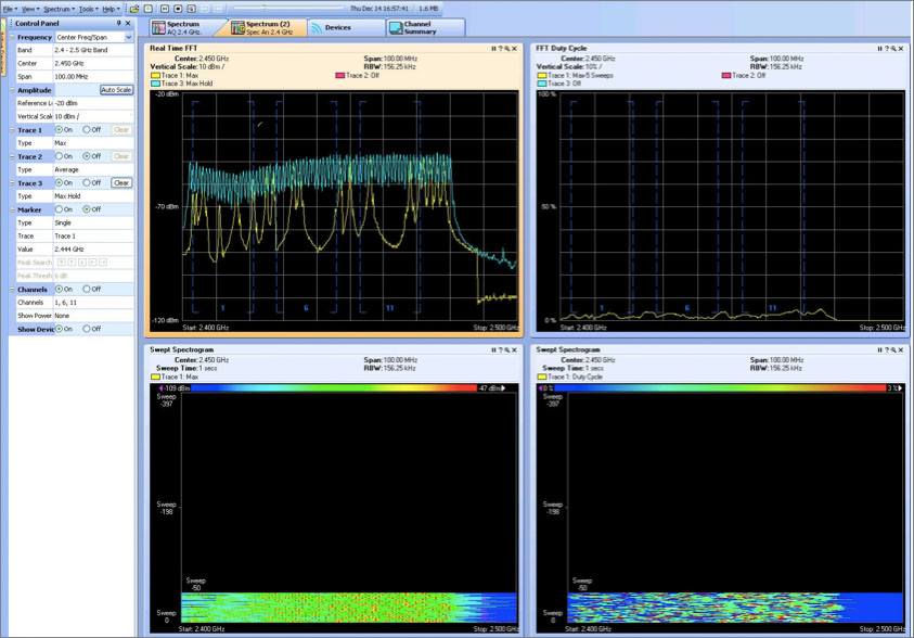
For the purposes of this book, it is not necessary to delve into Bluetooth specifics too deeply but rather to recognize it as an interference source, to understand its impact on the WLAN, and to know what it looks like in a spectrum analyzer trace. Bluetooth is easily identified in a spectrum analyzer by looking for the very high spikes (in a real-time FFT display) that cross all channels (since it’s a frequency hopping technology). Figure 15.2 shows an example taken from a Cisco Spectrum Expert card with the Max Hold setting enabled. You can see the unique Bluetooth signature in the Real Time FFT chart, but in areas with heavy usage and a busy RF medium, the Swept Spectrogram chart may be more useful for identifying Bluetooth. As you can see, there is a characteristic set of “dots” across the entire band.
FIGURE 15.2 Bluetooth as seen from Cisco’s Spectrum Expert
Wi-Fi Interference
One of the most commonly overlooked WLAN troubleshooting topics is the impact that Wi-Fi can have on itself. Many engineers tend to gravitate and stick to the search for non-Wi-Fi interferers, when in reality a large majority of issues are caused by Wi-Fi interference, which can be minimized with proper design techniques. As explained earlier, there are two main types of Wi-Fi interference. There’s the Wi-Fi interference that’s created by your own APs on your network. Then there’s the Wi-Fi interference that’s caused by either rogue APs on your network or a neighboring network that is in close proximity. The following sections cover the most common sources of Wi-Fi interference.
Co-channel Interference
Co-channel interference occurs when you have more than one AP on the same channel within RF range of one another, meaning the APs and either all or some of their associated clients are able to “hear” one another’s transmissions. Why is this bad, you might ask? Well, remember that wireless is a polite protocol and is based on the CSMA/CA principles of listen before talk. If you have multiple APs that are able to clearly “see” neighbor stations on the same channel, essentially what you have is all those clients plugged into a hub. They are all sharing the same channel, commonly called a contention domain.
Now suppose you have three APs on channel 11 and each AP has 10 clients and all of these APs and clients can clearly decipher one another’s transmissions (most importantly, the Duration/ID field in the MAC header). The net result is that only one out of 30 of those clients can talk at a time. Now imagine those same three APs but this time their output power is reduced and their spacing or channel assignment has been changed so that their transmissions are either not heard by one another (or associated clients), or, if they are heard, the amplitude is near the noise floor. By separating them into different contention domains, the result is that 3 out of 30 can transmit at the same time. With this basic example, you can see what impact co-channel interference can have on cell capacity and the overall throughput of your wireless network. Although 3 out of 30 may not seem like much, this is triple the previous capacity.
So where did all this co-channel interference come from? Two places: either your own network or someone else’s!
Operator-Owned Wi-Fi Interference
Let’s talk about co-channel from your own network first. Over the past few years, wireless networks have been making a fundamental shift from coverage-based networks—meaning a network that was designed to cover as much area as possible with as few APs as possible—to capacity-based networks, which essentially means you’re trying to cram as many APs into an area as you can to increase your capacity. Let’s be clear here: designing for a capacity-based network is no easy chore. Many engineers make the mistake of thinking they can increase capacity by simply adding more APs to the network. This is not so. What they end up doing is adding more co-channel interference to their already stressed network. There are specific factors that should be planned for when attempting to increase capacity. Some of these methods are as follows:
- Adjusting transmit power
- Using more directional antennas as opposed to using omnidirectional antennas
- Disabling lower data rates
- Placing APs so that you utilize a building’s natural RF characteristics to provide isolation between APs (APs in rooms versus hallways, etc.)
And even with these techniques, there is always a capacity limit. Smaller AP cells with lower transmit power will eventually cease to yield gains because an unwanted signal (usually between −75 dBm and −90 dBm) also increases outside the desired basic service area (BSA).
Neighboring Network Interference
The second source of co-channel interference is from networks that are not under your control. These can be from rogues (either infrastructure or ad hoc) that are within your building, or from APs that are simply neighboring Wi-Fi networks that could be from a tenant occupying space within nearby RF range of your building. The challenge here is that it’s easy to fail to realize that you have a neighboring network that’s impacting yours.
The Not-So-Friendly Neighbors
A customer calls you and requests assistance with troubleshooting what they describe as a performance issue on their wireless network. This is a network you designed and deployed, and you’re shocked to hear this since you are confident the network has properly placed APs and correct antenna alignment, that channel and power settings are optimal, and that you’ve disabled lower data rates (1, 2, and 5.5 Mbps). Yet you are now getting complaints of poor throughput and poor user experience. You tell the customer you will visit this problematic area and see what you can figure out.
When you get to the client site, you go to the problematic area and perform basic protocol analysis. You see a rogue network occupying the same channel as your AP (e.g., channel 1). Next you check the per-channel utilization and throughput for channel 1, as shown in Graphic 15.1. You are shocked to see that nearly 90 percent of your channel is being consumed by 1 MB traffic even though you have that data rate disabled and you are beaconing at 11 MB. What is happening here?
What you find is a busy neighboring network, one that is broadcasting several SSIDs with the lower data rates enabled. Remember, just because the hardware will let you configure a high number of SSIDs, that does not make it a good idea. The AP has to send beacons for each one of those SSIDs, and with the lower data rates enabled, it’s sending those beacons at 1 Mbps. Now let’s factor in user traffic, both from your own network and from the neighboring network.
If you’re in a situation where you have a neighboring network that’s doing something like this, the best defense is good social tact. The neighbors aren’t doing anything legally wrong, but they are being a bad RF neighbor. The best you can do is find where this traffic is coming from, approach the person responsible for that network, and kindly suggest that they take some action to help alleviate the situation.

Adjacent-overlapping Channel Interference
Adjacent-overlapping channel interference occurs when you have an AP that is on a channel that is overlapping with another channel. Its effects are somewhat similar to co-channel, but they may be worse. In the United States, for example, the three nonoverlapping 2.4 GHz channels are 1, 6, and 11. So, assuming you have APs using those three channels, if you were to have a rogue AP operating on a channel other than those three, it would impact two of those three channels. The 2.4 GHz ISM band channel plan shown in Figure 4.1 earlier in this book helps illustrate this problem.
In the 5 GHz spectrum, all of the 20 MHz channels are natively considered to be nonoverlapping since the channelization pattern was specified for easier configuration. However, since there are far more available channels in the 5 GHz bands, we recommend that you try to space at least one channel between adjacent cells. Even though the primary OFDM signals don’t overlap on the main channel, the secondary “shoulder” may overlap at a lower amplitude. At high transmit powers, this could have a negative impact on adjacent channels. Figure 15.3 illustrates UNII 1 and 2 frequency bands.
FIGURE 15.3 UNII 1 and 2 channel usage.

As a general recommendation, when troubleshooting performance issues on your wireless network, pay close attention to both co-channel and adjacent-channel interference sources.
Security Model Analysis and Troubleshooting 802.1X Authentication
To troubleshoot client authentication using 802.1X, you should break down the key components of the end-to-end infrastructure and follow a modular troubleshooting approach. The three key components involved in 802.1X authentication are the supplicant, the authenticator, and the authentication server.
Authentication failures are generally caused by misconfigurations, certificate provisioning errors, or a credential mismatch between the supplicant and the authentication server. In Figure 15.4 you see an entire EAPOL exchange between the supplicant and the authenticator that results in a failure.
FIGURE 15.4 EAPOL exchange between supplicant and authenticator from start to failure
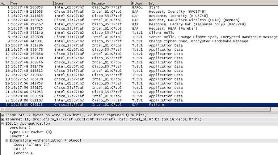
Knowing that the authenticator is simply a pass-through device, you can work your way back to the authentication server where the failure message originated. Figure 15.5 displays the RADIUS exchange between the authentication server and the authenticator.
FIGURE 15.5 RADIUS exchange between the authentication server and the authenticator

The EAP identifier (Id: 15) and code (Code: Failure) within the EAP message of the RADIUS packets are the same as the EAP values in the EAPOL trace (Figure 15.4) that is used to match up the EAPOL and RADIUS packets. To identify the root cause of the failure, you must understand why the authentication server rejected the client authentication. You can do this by checking the authentication server logs during the time period of the failure and searching based on the supplicant’s MAC address or calling-station-id (RADIUS attribute 31).
The most common causes for an Access-Reject from the authentication server are mismatched credentials, protected access credential (PAC) or certificate failure, and EAP type mismatches. In scenarios where the supplicant has an invalid certificate or PAC, the supplicant may not respond to the EAP identity request sent by the authenticator, and the process will not result in an Access-Reject and will not typically show up as a failure in the authentication server failure logs. However, you should see these types of failures in the authenticator logs as a message indicating an EAP timeout where the client failed to respond within the appropriate amount of time.
EAP timeouts can also occur when the authenticator’s EAP timers are set too aggressively. This issue occurs in scenarios where supplicants installed on older client devices take a long period of time to respond, especially during EAP-Fast PAC provisioning or during the EAP-TLS certificate key exchange. Other causes may be if the supplicant is waiting for user input and has prompted the user to select a certificate, enter a username and password, or change their password. If the EAP timeout on the authenticator is too short, the user will not have time to take the appropriate action on the supplicant.
When a certificate expires or becomes invalid on the authentication server, the server should immediately stop using the EAP types that are tied to the expired certificate. This will result in an Access-Reject and a failure message on the authentication server stating that the EAP type is not allowed or no longer configured (unless the supplicant and authentication server are able to negotiate a different EAP type).
When the supplicant and authentication server are configured with mismatched EAP types, the client will send a negative acknowledgment (NAK) message to the authentication server with the desired authentication type that it is configured for. You can see this exchange in Figure 15.6.
FIGURE 15.6 Packet #5 showing the NAK message

In Figure 15.7, the supplicant responds with an EAP NAK message with a desired EAP type of 25, which is PEAP.
FIGURE 15.7 EAP NAK message displaying EAP type 25

As you can see from Figure 15.6, the authenticator sends an EAP failure message to the supplicant indicating the authentication server is not configured to allow PEAP.
Failures can also occur between the authenticator and the authentication server where you do not see any response coming back from the authentication server. To identify the root cause of the failure, you will need to check the logs on the authentication server to see why it is not sending a response back to the authenticator. You may have to use a network sniffer to ensure that the RADIUS packets sent by the authenticator are being received by the authentication server. Typically this behavior is caused by:
- The authenticator’s IP address is not configured as a NAS or AAA client device on the authentication server.
- A shared secret mismatch has occurred.
- Communication ports (usually 1812 or 1645) are mismatched or otherwise incorrect.
- There is a key wrap configuration mismatch.
- The RADIUS service has stopped running on the authentication server.
- General network issues exist that prevent the authenticator and authentication server from communicating.
The authenticator should be configured to send SNMP or syslog alerts when the authentication server is unreachable as this type of failure will prevent the authenticator from allowing any users to authenticate.
Quality of service (QoS) allows the wireless LAN system to prioritize selected network traffic over other types of traffic. Without QoS, all user traffic will have the same priority and will be transmitted using a best effort, “listen-before-talk” algorithm where each device waits for a random backoff time and then transmits only if no other device is transmitting at that time. During times of congestion, delay-sensitive traffic such as voice and video can suffer from degraded quality as traffic load increases.
As a quick rehash from Chapter 10, “MAC Layer Design,” 802.11e uses Enhanced Distributed Channel Access (EDCA) traffic classes to provide multiple traffic classes and queues for transmission. Each traffic class can have its own AIFS, CWmin, and CWmax values, which are used to help determine the wait period before transmission. Traffic classes with the smallest AIFS, CWmin, and CWmax values have statistically the best chance to get access to the RF media.
Wi-Fi Multimedia (WMM) is a traffic prioritization method created by the Wi-Fi Alliance, which is based on the 802.11e standard that is used to determine the assignment of traffic classes based on four access categories (ACs):
- Voice
- Video
- Best effort
- Background
The WMM ACs are designed to easily map to 802.1p, also known as class of service (CoS) and IP Differentiated Services Code Point (DSCP) priorities for interoperability with the wired network. Non-WMM-capable clients that are not assigned to a specific AC are categorized by default as having best effort priority.
To ensure end-to-end QoS priority, inspect the proper QoS priority markings at each endpoint. This can be an arduous task, but it is important to identify where the problem breaks down if you are to preserve application performance. Figure 15.8 shows a packet from a WME-capable wireless device.
FIGURE 15.8 Packet from a WME-capable device

You can see the 802.11e UP value is marked at 6. If your client devices are WME capable and configured for a specific AC and you are not seeing the 802.11e AC marking, you will need to check to make sure the WMM parameter information element is set in the beacon, probe response, and association response frames from the AP radio. Also ensure that WMM is enabled on the WLAN that the client is associated to.
In Figure 15.9, you see a packet from the AP to a wireless IP phone.
FIGURE 15.9 Packet from AP to wireless IP phone marked as Best Effort

In this voice packet you see the packet is marked as Best Effort. You can work your way back to the sending IP phone to see where the QoS marking is dropped. We recommend that you perform end-to-end QoS tests for devices that are using delay-sensitive applications such as voice and video by verifying that the proper QoS classification is set at each end station:
Wireless Devices For wireless devices you must verify the proper 802.11e value is set. If the value is not set properly, it is important to understand the packet flow between the two wireless devices. Also note the direction of the traffic when the QoS marking is set improperly.
Stand-alone APs For stand-alone APs, the wired 802.3 Ethernet frames will be transmitted and received locally at the Ethernet port and separated with the use of 802.1Q VLAN tags. The stand-alone AP should be configured with proper 802.11e-to-802.1p mappings. If the 802.11e value is not marked properly for downstream traffic for wireless clients associated to different APs, you will need to ensure the proper 802.1p and DSCP markings are set and trusted on each Layer 2/Layer 3 hop between the two APs. Do so by reviewing the switch and router configurations or using a network sniffer at each hop to verify the 802.1p and DSCP markings. If you are seeing the improper marking directly at the AP port, there is most likely an improper 802.11e-to-802.1p mapping configured on the AP.
In Figure 15.10 you see the voice packet on the wired network is properly marked for a configuration where the 802.11e UP value is mapped to an 802.1p value of 5 and the switch is configured with a CoS-to-DSCP map where the CoS of 5 is mapped to a DSCP value of 46. We see the traffic is tagged with an 802.1Q VLAN tag of 111 with an 802.1p marking of 5 (shown as “PRI: 5” and encoded as 101, which equates to a UP of 5). The IP DSCP marking is also properly set to 0x2e (the “2e” here is the hexadecimal representation of the decimal number 46), as shown in Figure 15.10.
FIGURE 15.10 Packet with properly marked DSCP

For APs that operate in a centralized, controller-based system, the wireless traffic is typically tunneled between the AP and wireless LAN controller. The outer IP header of this tunneled traffic should also be marked properly for end-to-end QoS.
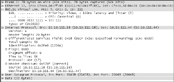
For tunneled traffic that is sent upstream from the AP to the controller, the 802.11e UP value is typically used to determine the value of the DSCP marking in the outer IP header and the DSCP marking in the inner packet is left intact; the DSCP in the outer header is typically used by the controller to mark the 802.1p value for the de-encapsulated traffic going out to the wired network. For traffic that is received at the controller from the wired network, the controller typically uses the original DSCP value of the received packet and marks the DSCP of the outer IP header with the same marking, which is then used by the AP for 802.11e. In Figure 15.11, you see a packet that is captured from a CAPWAP-based wireless LAN controller. The inner CAPWAP packet carries the original wireless data with a source IP of 10.10.111.18 that is marked with a DSCP value of 0x2e; the outer IP header is also marked with a DSCP of 0x2e. When the wireless controller de-encapsulates the packet and sends the traffic out to the wired network, the 802.1p value should be marked with the appropriate value based on the configured 802.11e-to-802.1p mapping and the IP DSCP marking of the inner packet is typically left intact.
FIGURE 15.11 Packet from a CAPWAP-based wireless LAN controller

In Figure 15.12 you can see the same packet (with the same IP DSCP of 0x2e) when it is de-encapsulated from the tunneled CAPWAP packet, which carried the original IP DSCP of 0x2e. The controller is configured to mark this traffic with an 802.1p value of 5, which you see is properly marked. You can confirm this is the same packet because the IP Identification of 0x2fe8 (12264) matches in both traces.
FIGURE 15.12 De-encapsulated CAPWAP packet
In Figure 15.13 you see a correct IP DSCP of 0x2e, but the 802.1p value is set improperly to 0.
FIGURE 15.13 802.1p value incorrectly set to 0

This improperly set 802.1p mapping is typically caused by a router or switch between the AP and the wireless LAN controller that was not properly configured to trust the DSCP in the outer IP header (which was set by the AP based on the wireless client’s 802.11e UP value). We recommend that you use a network sniffer to verify the DSCP marking in the outer IP header at the controller port. If the DSCP in the outer IP header is marked improperly at the controller port, there is most likely a QoS misconfiguration on the controller, or perhaps the switch port that the controller is attached to is not properly configured to trust the 802.1p value being sent by the controller. If the outer IP header DSCP value is not marked properly, we recommend that you sniff the AP port to verify the AP has set the correct DSCP value in the outer IP header. Then verify each L2/L3 hop from the AP to the controller to find where the DSCP value is being re-marked by checking the router and switch configurations or by using a network sniffer.
Whenever critical real-time traffic is deployed in a wireless LAN, you should always verify at each endpoint that you are seeing the proper QoS markings. It is important to understand the QoS translations between 802.11e, 802.1p, and IP DSCP to pinpoint where the classifications are being lost.
When it comes to troubleshooting enterprise wireless networks, you cannot rely solely on the wireless components as the focus of your troubleshooting effort. The clients and the wired network can often be the cause of the issues that occur on the wireless network. In this section, we’ll dig into some common causes of issues on the wired and client side.
Controller and AP Provisioning
APs that operate in a controller-based environment need to be provisioned to discover a wireless controller to operate properly and pull down the proper configuration and software version. Typical controller-based APs will use the IP protocol to communicate with the wireless controller. For controller discovery, the controller-based APs generally use DHCP options that carry the wireless controller’s IP address. To ensure the AP can join the wireless controller, check that:
- The AP obtained a proper IP address on the correct VLAN and IP subnet
- The AP can contact its default gateway
- The AP can discover the wireless controller IP address
- Communication is not blocked by access lists or firewalls
For normal troubleshooting, you can verify IP reachability by issuing ping and traceroute commands from the wireless controller to the AP. You can also sniff the AP and wireless controller port to ensure proper communication. Examine the Address Resolution Protocol (ARP) cache on the default gateway of the controller to check for a duplicate IP address where another wired device is using the same IP address as the controller. The ARP cache on the controller’s default gateway should map the controller’s IP address to its MAC address. You can also sniff the wireless controller VLAN and clear the controller IP address from the ARP cache. Then ping the controller IP; if you see more than one device respond to the ARP request, you can track down the MAC address of the other devices that respond to the ARP request to the controller IP.
Client IP Provisioning
For client IP provisioning, the wireless client will send a DHCP discover/request as an all-subnets broadcast. If the DHCP server is across a Layer 3 boundary, the first hop router must be configured as a DHCP relay to forward the broadcast to the DHCP server. Also you must ensure there is IP reachability between the DHCP server subnet and the client subnet. The DHCP server should be able to get a ping response from the default gateway of the client subnet. The first hop router for the client subnet should have an entry in its routing table that includes the DHCP server subnet, and vice versa. If the routes exist and you are unable to ping and ICMP is allowed end to end, you should verify there is IP reachability via a traceroute to identify the last Layer 3 hop in the traceroute. In the case of a routing loop, you will see the traceroute bounce between the same two Layer 3 hops until the time-to-live (TTL) expires.
Trunking and Pruning
For APs where wireless traffic is locally switched on the AP, the client traffic is separated on the wired network using VLAN tags. You will need to ensure that all the necessary VLANs are allowed over each trunk link. For controller-based deployments, the wireless traffic on the AP may be centrally switched back to a wireless controller. In these deployments, the APs are typically connected on access ports with the VLANs trunked to the wireless controller. To avoid unnecessary VLAN traffic, you will need to prune all the unnecessary VLANs from each trunk link. Also be aware that most APs and wireless controllers do not participate in VLAN Trunk Protocol (VTP) or VTP pruning, so it will most likely be necessary to manually add and remove VLANs from each trunk link. You will also need to verify that the necessary VLANs are in a spanning tree forwarding state.
MAC Address Tables
When a wireless client is able to authenticate and associate to the wireless network but is unable to obtain a DHCP address or obtains an IP address on the wrong VLAN/subnet, it is a good idea to verify whether the wired network properly learned the client’s MAC address. To do this, check the switch’s MAC address table on the AP port for stand-alone APs and the controller port for controller-based environments. The MAC address table should include the client MAC address, ingress port, and VLAN ID.
General network troubleshooting requires you to be aware of how the client traffic is forwarded onto the wired network to verify that Layer 2 forwarding and Layer 3 routing is properly configured.
During the process of troubleshooting wireless LAN-related issues, a large amount of attention is often so focused on the underlying infrastructure that client-related issues are ignored or overlooked. In many cases, it is difficult to troubleshoot client-related issues due to the lack of control you may have over the client devices. Specifically, many enterprises don’t own all the clients on the network, and they have no authority to perform the necessary troubleshooting steps. Similarly, there is typically only one infrastructure vendor in operation on a network, but there are many different client devices with different capabilities, management utilities, drivers, and applications. However, client devices are responsible for a significant number of WLAN problems, and more times than not, the issue can be related to an old driver version or a low-quality radio in general. Not all radios are created equal; low-cost clients tend to be low cost because the hardware they use is cheaper. You can bet that it’s cheaper for a reason. For example, radios with low receive sensitivity are cheaper than radios with high receive sensitivity, but this parameter is important to communication fidelity. The following list examines common client-related problems:
Data Rates 802.11 WLANs support multiple data rates to allow clients to adapt to the diverse nature of the RF environment. Typically clients will downshift due to multiple 802.11 retries that are not ACK’d (or changes in RSSI, SNR, etc.) and upshift after multiple successful 802.11 transmissions. The method and rate at which the client downshifts and upshifts can vary between vendors and clients; some older driver versions may never rate switch properly. You must identify this behavior because clients that are stuck using lower data rates can cause an overall throughput drop to all stations associated to the same access point.
Sticky Clients While the wireless LAN infrastructure can influence a client’s initial association behavior, the roaming decision is made by the client device (except in the SCA architecture). Older client driver software is typically less optimized for modern, highly mobile enterprise environments because they were designed for early networks without fast roaming or only a single access point. In this scenario, the client will continue to stay connected to the associated AP until a wireless signal is no longer detected. In an enterprise environment, this will cause a significant delay when roaming between access points. This will often lead to scenarios where the client is associated to an access point with a poor signal in areas where there is strong coverage that is being provided by other access points. This situation poses a problem for both this and other stations in the same BSS since the “sticky” client will most likely stay associated using lower data rates and experiencing retransmissions, impacting performance for everyone. Certain client adapters may have settings that allow you to adjust the rate and signal level threshold (or general roaming aggressiveness level) where the client will attempt to scan for and roam to a better access point.
Bad Drivers We’ve already mentioned that drivers can have a significant impact on client performance. This impact comes in the form of poor roaming, low data rates, frequent disassociations, inconsistent protocol implementations, and other unexpected behaviors. In many cases, there’s no immediate explanation for a client’s erratic behavior other than a poor driver build or feature implementation. In these cases, the best approach is to test different driver builds or client software utilities, and attempt to identify the most stable combination. Depending on your infrastructure solution, you may also find that there is an outstanding bug or feature incompatibility with the infrastructure and client firmware. For client devices with modular WLAN adapter slots, replacing the radio hardware with a higher quality product with better driver builds may also be recommended.
The key takeaway for this section is that poor client behavior on a single client can affect the overall performance of all the clients on the BSS. It is important to ensure that all clients have current driver builds installed and are optimized to operate properly in an enterprise WLAN environment. Though this section makes up only a small part of this chapter, client troubleshooting is probably more common than any other type of troubleshooting because client devices are usually the guilty party when new, unwanted WLAN behaviors occur.
Common Troubleshooting Mistakes: What Not to Do
Over the course of troubleshooting wireless networks, you will begin to notice that sometimes things just didn’t go as they should have. As you’ll see in the following sections, things can go wrong during the installation process. How does this happen, you might ask? Well, it depends on the situation, but it’s easy to see that at times there’s a disconnect between the wireless engineer indicating where to place an access point and the person who actually places it. Some companies have special contracts in place when it comes to any and all equipment installation. In times like those, the technicians who install the AP might not understand how the technology works—and that can turn out to be a disastrous arrangement.
Figure 15.14 illustrates an AP mounted inside a metal enclosure with the dipole antennas turned flat against the metal enclosure.
FIGURE 15.14 An AP in a metal enclosure with dipole antennas touching a metal door

In this configuration, the omnidirectional dipoles act more like a directional patch as they have a large reflective object on the back side of the antenna. To make things worse, up to 50 percent of the energy is reflected back toward the radio, making the efficiency of the AP itself much less than its true capabilities. Finally, you should notice that it’s mounted up in the ceiling above metal water pipes and other metal objects. Always try to keep the AP closer to the clients when possible and away from materials that will block RF propagation. When APs must be mounted above the ceiling, make every effort to keep them as close to the ceiling tile or other ceiling material as possible. The further the AP goes into the ceiling, the higher the chance of excessive reflection, multipath, and signal attenuation due to ceiling tile grids, air ducts, cable trays, and so forth.
Figure 15.15 illustrates what can happen when an AP is installed and someone follows up after the installation and, without knowing what the AP actually is, creates a new problem.
FIGURE 15.15 Wall-mounted AP hidden behind new piping

To complicate matters further, this particular AP is designed to be ceiling mounted. That’s not to say it cannot be mounted vertically, but you must take into consideration that the RF propagation is not the same as it would be on the ceiling due to the large metal cooling plate that is on the back of the unit. Therefore, when wall mounting an AP, as seen in Figure 15.15, focus most of the energy away from the wall. Any intended coverage behind that wall will likely be inadequate.
Figure 15.16 is an example of a poor above-ceiling installation. The clients are obviously below this ceiling, and the combination of the AP in a metal enclosure, above the ceiling, and surrounded with metal ductwork and I-beams, is a multipath nightmare at best. At worst, it’s a black hole for signal penetration. So what can be done to remedy a situation like this one? You can leave the AP above the ceiling in the box then mount external antennae on the underside of the ceiling tile. Problem solved!
FIGURE 15.16 Example of a poor above-ceiling installation

Throughout this chapter you’ve learned various troubleshooting techniques associated with some common problems to wireless networks. As stated at the beginning of this chapter, there will always be a troubleshooting component for wireless networks. That being said, being proficient at solving complex issues will set you apart from your peers if you’re able to carefully dissect and solve problems.
When approaching a new issue, remember to be systematic: start at Layer 1 of the OSI model by checking physical connections. Ask yourself if power is being supplied and if antennae, cables, connectors, and adapters are connected and oriented properly. From there move through the model to determine if you have Layer 2 connectivity or if other problems are occurring with the protocols at this layer. You then should check Layer 3 connectivity and stability. Collect as much information and diagnostic material as possible, target common problems, find the consistencies in the problem, and take advantage of professional troubleshooting tools. Remember: debugs, protocol and spectrum analyzers, support forums, and surveying tools are your friends, so leave no stone unturned.
Use a systematic approach to troubleshooting. Reference the OSI model and start with Layer 1 before moving on to higher layers when eliminating potential causes for problems. Avoid making multiple changes at once as it is difficult to distinguish which change had which effect when multiple changes occur in unison.
Be able to validate coverage. Ensure the coverage area is receiving a quality signal that meets the design requirements. Use site survey software to analyze and spot problematic areas.
Understand the importance of quality of service. Be able to identify different methods commonly used to give preference to high priority traffic. Understand what happens on both the wireless and wired side of QoS markings.
Know how to troubleshoot security. Be able to troubleshoot the common failures that can occur during 802.1X/EAP exchanges.
Know how to avoid common mistakes. Be able to spot mistakes that happen during installations. Ensure that the design has been deployed as it was intended.
Identify sources of interference. Be able to identify sources of interference that are impacting the wireless network. Those may be Wi-Fi or non- Wi-Fi; understand the impact of each.
Validate the wired infrastructure. Not all wireless issues are purely wireless. Be able to troubleshoot common wired network issues such as DHCP and basic routing that can cause issues on the wireless network.
1. Which of the following is an example of non-Wi-Fi interference?
A. Co-channel interference
B. Bluetooth
C. Thunderstorms
D. Cosmic rays
2. Your company is located in a downtown high-rise building. You’ve configured your network so that your lowest mandatory rate is 12 Mbps. Users are complaining about poor throughput. Upon inspection, you notice that over 90 percent of the traffic is being sent at 1 Mbps. What is most likely the cause?
A. A software bug on the network
B. An AP that has lost its connection to its controller and is repeatedly sending management frames
C. Neighboring networks from above and/or below that are very busy and have the lower data rates enabled
D. Nothing, since this is normal
3. What are the key entities in the 802.1X architecture model?
A. Supplicant, authenticator, authentication server
B. Client, domain server, RADIUS
C. EAP, EAPOL, RADIUS
D. Authentication, authorization, accounting
4. What type of device is classified as an authenticator? (Choose all that apply.)
A. Access point
B. Radius server
C. Wireless LAN controller
D. TACACs server
5. When troubleshooting coverage issues for a wireless network as it appears to new client associations, you should perform which type of survey?
A. Active survey
B. Passive survey
C. Predictive survey
D. A survey is not necessary.
6. Which of the following are examples of Wi-Fi interference for channel 6? Assume all access points are within RF range of one another. (Choose all that apply.)
A. Other access points on your network that are on channel 6
B. Other access points that are not on your network but are on channel 11
C. Other access points that are on your network but are on channel 1
D. Other access points that are not on your network but are on channel 3
7. WMM prioritizes traffic across which four access categories?
A. Voice, video, best effort, background
B. CWmin, CWmax, TXop, AIFS
C. 802.11e, 802.1p, EDCA, CoS
D. EF, AF41, AF31, BE
8. Which of the following devices determine when a client will roam from one AP to another?
A. The access point
B. The wireless LAN controller
C. A combination of the wireless LAN controller and the client
D. The client
9. CAPWAP uses which of the following port(s) for discovery?
A. UDP 5246
B. UDP 12222 and 12223
C. TCP 5246 and 5247
D. TCP 12222 and 12223
E. UDP 1812
10. What protocol is typically used by the authenticator to communicate with the authentication server?
A. EAP
B. EAP over LAN
C. RADIUS
D. MD5
11. In general, troubleshooting should always start at what layer of the OSI model?
A. Layer 7
B. Layer 6
C. Layer 2
D. Layer 1
12. What QoS marking is set in the packet’s IP header?
A. 802.1P
B. EDCA
C. WMM
D. DSCP
13. How are EAP messages transported over 802.11 wireless LANS?
A. EAP-Fast
B. PEAP
C. EAPOL
D. EAP_TLS
14. To increase capacity in a coverage-based wireless network, which of the following techniques are typically recommended? (Choose all that apply.)
A. Turn up power on the access points.
B. Lower power on the access points and, after careful planning, add more APs.
C. Maximize airtime usage by disabling lower data rates.
D. Add additional APs and use directional antennas.
15. A wireless network with fewer APs at higher power levels to cover a large area is said to be which of the following?
A. Coverage based
B. Ideal for roaming
C. Capacity based
D. Destined for failure
16. Identify two types of key caching used for fast secure roaming. (Choose all that apply.)
A. PMK caching
B. 802.11N
C. EAP
D. CCKM
17. At which layer of the OSI model does ARP operate?
A. Layer 2
B. Layer 3
C. Layer 4
D. Layer 6
18. Where can you check to identify a duplicate wireless controller IP address?
A. IP routing table
B. CAM table
C. ARP cache
D. Spanning tree state
19. What are the four main EAP codes?
A. Request, Response, Success, Failure
B. Code, Identifier, Length, Data
C. Version, Packet Type, Body Length, Packet Body
D. Identifier, Length, Authenticator, Attributes
20. Which EAP type does the supplicant send to request a different EAP type?
A. Reject
B. Logoff
C. NAK
D. EAPOL Start
1. B. Bluetooth operates in the 2.4 GHz band, and although it is not Wi-Fi, it interferes with Wi-Fi since it shares the same frequency.
2. C. While it could potentially be a software issue on an AP, there’s a much higher likelihood that the traffic is coming from a neighboring network. Given that the question includes “a high-rise building,” option C is the best answer.
3. A. The three key entities are the supplicant, authenticator, and authentication server.
4. A, C. Access points and wireless LAN controllers act as the authenticator in an 802.1X network.
5. B. When troubleshooting, a passive survey is used to get a holistic view of the RF environment.
6. A, D. Access points that are either on channel 6, or are on a channel that overlaps with channel 6, will interfere with one another regardless of which network they belong to.
7. A. WMM access categories are voice, video, best effort, and background.
8. D. While the wireless network can have an impact on initial associations (such as with band steering or load balancing techniques), the actual roaming decision is made by the client.
9. A. CAPWAP uses UDP 5246 for discovery as defined by RFC 5415.
10. C. EAP messages are transported between the authenticator and the authentication server using the RADIUS protocol.
11. D. Troubleshooting should always start at Layer 1 (the physical layer). By troubleshooting from Layer 1 to Layer 7, you have a systematic approach for eliminating possible causes of the problem.
12. D. The IP DSCP marking is set in the IP header.
13. C. EAP messages are delivered over 802.11 wireless LANs using the EAPOL protocol.
14. B, C, D. Increasing power is not often an effective means of increasing capacity. To increase capacity, you must usually isolate contention domains. This is done through use of lower-power APs, directional antenna use, and the disabling of low data rates.
15. A. Fewer APs at higher power is indicative of a coverage-based network.
16. A, D. PMK and CCKM are two key caching schemes used for Fast Secure Roaming.
17. A. ARP is a Layer 2 protocol that maps Layer 2 hardware addresses to a Layer 3 address such as an IP address.
18. C. Check the ARP cache on the default gateway of the wireless controller to identify a duplicate controller IP address.
19. A. The four main EAP codes are Request, Response, Success, and Failure.
20. C. The supplicant sends a type 3 NAK response to request a different EAP type.