
Chapter 13
Documentation and Finalizing the Design Solution
THE FOLLOWING CWDP EXAM TOPICS ARE COVERED IN THIS CHAPTER:
- Implement and understand the role of documentation in network planning and design.
- Describe processes and best practices related to documenting collected survey data and generating a deliverable report.
One of the most important deliverables to your customer or upper management (if you are designing a WLAN for your own company) is the design documentation. In this chapter, we will focus on the different types of documentation deliverables that need to be produced for any WLAN design effort.
In Chapter 9, “Site Survey RF Design,” we discussed the RF survey process and generating data on which to base your final design. This chapter addresses how to take that information and provide a documentation set that includes the design decisions for AP placement. As you’ll see, not all projects are created equal; some can be very large in scope and some can be very small—even consisting of just a single AP. When the scope of the WLAN increases, the amount of documentation that is required usually increases along with it. Regardless of size, documentation is still needed. The size of your documentation and how it fits your project is also an important topic and one we’ll cover in this chapter.
Other common design documents we will explore include the high-level design (HLD), low-level design (LLD), and operational and maintenance planning documents. This chapter will discuss each of these documents and what type of content needs to be included in each.
There aren’t many people who actually like to create documentation. It is an arduous and often time-consuming task. What’s more, a variety of factors, including customer preference, seem to often necessitate a need to revise. Yet, it’s critical to create reliable documentation for your project. In fact, in regard to success factors, it is second only to making sure the product, a WLAN design in this case, accomplishes what it sets out to do and effectively works.
The Importance of Documentation
When I (Shawn) was 18 years old and attending my first year as a computer science major at Cal Poly San Luis Obispo, my professor, who was one of the most senior members of the department staff, stood up in front of the class and said, paraphrasing of course, “The goal of all computer programs is, one, that it is correct. Two, that it is documented very well.” I can’t even remember what the third item was anymore, but what I do remember is that she never said efficient, fast, or anything even related to that. I was 18 years old then, and she was nearing retirement age and I thought to myself, “Geez, she doesn’t have a clue.” I agreed with her assessment that it is important for the code to be correct. After all, a software program that provides erroneous results is useless. It’s like a calculator that doesn’t divide properly. But I couldn’t understand her reasoning for placing documentation second on the list. After spending over 15 years in the professional world, I now know that the professor was right and I, the know-it-all 18-year-old freshman, was the one who didn’t have a clue.
When all is said and done and any project is complete—especially a project that results in a complex technical system—documentation is essentially all that there is to leverage in group discussions, troubleshooting efforts, and just about any activity that involves any number of interested parties in any part of the life cycle of the product.
For example, if you design a solution and one of your colleagues has to work on it while you are away on vacation, you will experience the importance of documentation. Similarly, what would happen if you left the company? Documentation is also critical when dealing with an older project, even if it was your own project that you designed. There are simply too many details that can be lost if they aren’t put into some form of documentation that can be referenced later.
Hopefully these points have sold you on the value of providing good documentation. Maybe we have even inspired you to author great documents. Documentation comes in many forms; there isn’t a single format that we can prescribe for all WLAN designs. What we do aim to accomplish in this chapter is to provide a solid and flexible foundation that should suffice in the smallest of projects to even the largest of them. In general, the larger the scope of a project, the more people are involved and the greater amount of documentation needed.
For example, a single WLAN installation at even a large enterprise facility may not require a large amount of documentation, relatively speaking. However, if the documentation is a template for a new WLAN standard that will be deployed across many locations in a variety of environments that may involve multiple teams, you can bet that a solid base of documentation will be one of the single most important fruits of your labor.
Let’s now discuss the different audiences of your documentation and also specify a minimum set of requirements that should be included in a WLAN documentation set regardless of size and complexity.
Audience
When writing documentation, have an audience in mind. Each audience will require different data sets and presentation styles, so you will often find that, as the designer, you will have to put yourself in many different people’s shoes as you create documentation. Management and end users require a different set of information than IT support staff who will be maintaining the design in the operational phase of the life cycle. To provide some guidance on how to address each of these audiences for your documentation, we will discuss each audience type below. Most of this chapter focuses on the technical audience, as these are the people who will implement, operate, and make future revisions to your network design.
Management
This audience demographic usually requires the smallest amount of documentation for direct consumption. Their support staff may be involved in the detailed components of the design, but usually management requires simply an overview.
Communication goals that need to be addressed to management are usually included in an executive summary. You typically summarize design requirements and how they are met by the proposed design.
Management will also usually be looking for a high-level diagram of the WLAN design and how it fits into an existing diagram or framework with which they are already familiar (ideally). It is advisable to look for existing diagrams that may fit this bill instead of creating something from scratch. If nothing currently exists, you can use a baseline diagram to illustrate the current environment and then display the same diagram with the proposed WLAN design changes.
Even though we will focus on technical design documentation in this chapter, it’s important to note that whenever talking with management, you should explain the virtues of the design and any benefits that are worth repeating or referencing. This strategy is helpful whenever management plans to speak with other colleagues and interested parties of various types.
Engineering
Engineers can fall into multiple categories depending on the size of the IT team and the organizational structure. In some smaller organizations, engineers may be the architects and planners for new standards as well as the people creating the detailed design. Yet larger organizations usually have separate roles for each of these tasks.
The task of engineering in a larger organization enters into the equation after a product direction and a design standard have been chosen. Usually, engineering leads are consulted for the standard development, but they are usually the main consumers of the high-level design. Specifically, engineering will take the design standard and develop a low-level design (LLD) for a particular site. Therefore, project documentation is key to the engineering staff where they, in turn, further develop documentation for their implementations.
Implementers
When a design has been created and detailed specifications exist that define a new deployment, the role of the implementer is to facilitate getting the design installed. An implementer is often a field engineer, a network technician, or the like. Some organizations combine the role of the implementer and the engineer, though they are usually separate roles in larger organizations. Implementers are typically responsible for racking/mounting, labeling, and cabling equipment, whether the equipment is in closets or throughout the facility, as with APs. Engineers can provide preconfigured devices for the implementers or, depending on the organization, provide configurations or detailed instructions for the implementer to configure themselves.
If implementers will be involved in designs you are developing, consult with them to see what documentation items would be helpful to them. Perhaps they may have a request for specific fields and nomenclature that you should include.
Support Staff
Once a design is installed and is being used, a different team of people provides support. They are the first line of defense for the end users who are the consumers of your new WLAN design. Operational support usually leverages a help desk ticketing system where end users can generate problem reports and the resolution can be tracked. Software and driver updates, patches, and onsite troubleshooting and analysis typically start with the operational staff.
Operational support teams are also the ones who may suffer from bad design decisions. It is important that a feedback loop be created to allow for problem reports to make it back to the designers of the WLAN. When problem reports become larger issues, it is also important that they be able to escalate issues back to engineering and maybe even designers of the WLAN if the problem is significant enough.
Minimum Requirements
WLAN designs may be anywhere from a few APs all the way to multiple sites spanning international boundaries that support thousands and thousands of devices with large numbers of technical staff involved in the process. Regardless of size, there is a minimum set of documentation that is always necessary.
Documentation for WLAN designs is different from other types of networking designs. You can say that WLAN designs are network designs with an additional component: RF. There might be unique construction elements as well, but largely the primary difference is the RF factor. From a network perspective, usually the minimum level of network documentation is a low-level network design document that provides the following:
- Some form of RF documentation that illustrates why APs were placed where they were and what the signal coverage was at the time of the survey
- Logical representation of the network
- A physical network design that shows cabling, mounting locations, and other details
RF Design
One of the most important details when troubleshooting a WLAN is documentation of AP locations and the RF environment. This information is the result of the site survey process as defined in Chapter 9.
Once an RF design is determined, final selection of exact AP placement as well as antenna choices and mounting methods need to be documented. Each AP placement should minimally include the following information:
- A description of AP locations—a text description of where the AP is placed, including nearby rooms, markers, or other identifiable sources
- A map of AP locations
- The AP make and model
- Mounting details
- Antenna selection and orientation (if applicable)
- The power level used in the original survey
- RF channel (only when automated channel management isn’t used or specific channels need to be avoided, such as when interference was found)
- Cabling and power considerations, such as cable media type, termination, origination source, and power source
Including Photos in Your Documentation
Photos are often a debated topic with AP placement documentation. They can be incredibly valuable to installation teams to identify exact AP location, mounting considerations, or any other detail that needs to be called out. On the other hand, they may provide very little value and unnecessarily bloat the size of the document.
Two problems are often found with photos included with site survey documentation. The first problem is when no identifiable markers are included in the photo. For example, let’s say that an AP is supposed to be mounted in an indoor location from a suspended T-bar ceiling. T-bar ceilings often look in one place just like every other place where a similar ceiling is installed. When these photos are taken, be sure to include some identifiable characteristic of the area that is unique.
The second common problem is just the opposite. That is, instead of focusing too closely on one area with no distinction, photos of distant locations are submitted. Without adequate zoom into the specific area of interest, the photo provides no additional value to the audience of the document.
The bottom line is that if photos are included for AP placement, you should make certain they have an explicit purpose and provide value to the installation team.
AP locations also need to be very clearly documented on maps. A single, clean map with AP locations, their labels, and even the base radio MAC address for each radio can greatly enhance troubleshooting efforts. A second map that also shows signal coverage from an actual site survey is valuable as well. Ideally, the final coverage map is one that is based on a post-validation survey—one that is performed after all APs and antennas have been placed.
Logical Network Design
Logical network designs show all of the system components and the path by which data flows in the system. As opposed to a physical topology, a logical network design is independent from the physical interconnections made between network components. During documentation, each system component should be labeled along with its network addresses. Often icons are used to represent system components with lines in and out of them to represent links between components, such as the one shown in Figure 13.1.
FIGURE 13.1 Sample logical network design

The WLAN controller as shown in Figure 13.1 shows a connection to the network core. The physical connection(s) to the WLAN controller can be any type of EtherChannel link that can be configured in a variety of ways. For example, two, four, or more physical Ethernet links can be used in an EtherChannel configuration and bonded together to obtain greater bandwidth and redundancy.
The logical network design documentation is one of the most important documents to convey your design to a large audience. Showing network devices, where they are located in the network hierarchy and logically how they are connected, abstracts the finer details that do not matter to a larger audience.
When drawing links between systems in logical network designs, you should provide only enough detail to convey the medium, such as Ethernet and wireless, and include information such as the VLAN number or the SSID.
Some logical designs go as far as providing device names and IP addresses, but this may not always be necessary to convey logical design concepts.
Physical Network Design
Because logical network design documents do not explain details of how network devices are connected to each other, we usually place that detail into physical network design documents. Physical network documentation should specify the following:
- Actual ports used on the local network device
- Ports used on the peer endpoint from the local device
- The media type by which the devices are connected
- MAC addresses, IP addresses, and/or actual device names, in order to clearly identify which device is being referred to
Eliminating as much ambiguity as possible is one of the major goals of physical network design documents.
An example of a physical network design appears in Figure 13.2.
FIGURE 13.2 Sample physical network design
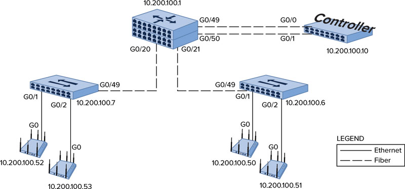
Notice that each device shown in the design has each physical connection to other devices clearly documented. The physical port that each cable is plugged into is shown in the document along with the media type of the connection. Furthermore, each device is shown with the specific IP address it has been assigned. Your organization or customer may prefer to use a device name that will also be entered into the DNS server.
Physical network designs should also have a spreadsheet of the network devices and important information documented such as IP addresses, VLAN assignments, MAC addresses, serial numbers, and other important details.
High-level designs (HLDs) are primarily used to provide an overview of a WLAN design solution. As it fits into the larger documentation scheme, the HLD is like a general design framework around which specific design components can be built. It provides a set of standards (such as vendor selection and deployment architecture) that facilitate a certain amount of design continuity across the enterprise. The importance and extent to which HLDs are used in some organizations will vary. HLDs are often included to convey a network design standard that can be used in a number of network implementations. Larger networks of significant cost usually incorporate HLDs because of the amount of attention paid to larger projects by upper management and other key stakeholders.
Single implementations usually do not produce a separate HLD document. These installations may simply combine elements from an HLD into a low-level design (LLD) document, which we will discuss later in this chapter.
If you’re in a larger organization and deploying a new WLAN technology, you can create an HLD document that discusses the following:
- Details of the design that relate back to business and technical requirements.
- Services that are provided by the new design standard
- An architectural overview
- Specific mention of the primary WLAN applications of data, voice/video, location, and guest network services
If you are deploying a number of sites based on a single design methodology, you should develop an HLD that will then be used to help encourage conformity to the design team’s goals.
We will now review the various document sections that you should include in an HLD document. Use these sections as a starting point and include or omit specific sections based on your audience, organization, and design needs.
Executive Summary
An executive summary is used in a variety of business documents and serves the purpose of summarizing the entire document at a high level so that a busy executive need only read that single section to understand the core concepts of the design. It is possible that an executive will skim the rest of the document, but many do not get past the executive summary.
Executive summaries should include the following:
- Business objective mapping that discusses how the design meets major business requirements
- A description of the other goals of the project and how the design meets them
- A section that highlights any concerns the client should be aware of and how they can support addressing them
- A brief illustration of other important benefits of the solution that may not have been covered by the business requirements and goals
Engineering Summary
HLD documents for larger WLAN designs can be quite long. Engineers and implementers who are producing individual designs based on them do not always want to or have time to read a lengthy document. Ideally they will read the entire document, but you should also include a summary section for engineers that includes hard-hitting and design summary information that they can quickly reference. This section should clarify details that may not be easily picked up in a large document.
Any type of design information that can be summarized into tables and cheat sheets should be included in the engineering summary section. Examples may include, but are not required or limited to:
- Decision criteria for device placement
- Decision criteria for subnet sizing
- Decision criteria for VLAN numbering
- Decision criteria for redundancy
Background and Goals
This section of the document addresses background and goals and should at least include a review of the business and technical project requirements. It may be important to also summarize the business driver for WLAN design and certain information that might be important to a designer.
Some organizations also have to adhere to regulatory policies or their own internal standards. When this is the case, you should reference these policies and discuss how the design addresses (or does not address) concerns related to these policies.
Services and Applications
In Chapter 3, “Designing for Applications,” we discussed several types of WLAN application types: data, voice/video, location services, and guest access. In this section, you should call out specifically which type of applications the WLAN is being designed to accommodate. You can go into detail under each of these categories if there are additional details that you think your audience will be looking for.
If voice and video are applications that your design will be supporting, you should detail the QoS design and features you are specifying in the HLD. This must include both wireless and wired QoS configurations. Guest networks may also have QoS markings in order to place that traffic into the lowest possible QoS queue.
Architecture
In this section that covers architecture, it is a great opportunity to indicate the specific platform(s) the design is based around, which includes the vendor and make and model. You should mention specific components of the overall solution and their function within the design.
For each type of make and model, it is important to describe the type of data forwarding model. Chapter 5, “Vendor and WLAN Architecture Selection,” discussed several types of WLAN architectures and modes of data forwarding.
Redundancy design is another important topic to include in this section. Include design details about the WLAN equipment itself as well as other elements of your design that address redundancy elements related to LAN connectivity, power supply, or other areas.
Diagrams are another important element to include in this section. Diagrams should only be logical network diagrams in an HLD document. They should detail the topology of the network and where the WLAN components reside in the overall LAN hierarchical design.
Finally, include a section on security design. It’s important to document where the authentication server fits into your network design. If possible, the network distance from the 802.1X authenticators (APs or WLAN controllers) should be apparent from the diagram.
If you’ve ever heard the saying “The devil is in the details” and it didn’t fully sink in, it will once you’ve authored a low-level design (LLD) document. This document takes the design that has been outlined by the HLD document and fleshes out all the intricate details that are required to successfully deploy the design. It’s essentially the DNA of a network design and should give any engineer who reads it a solid understanding of how the design is or will be deployed and the configurations that make it work.
LLD documents are usually based on implementations of a single WLAN installation. The LLD documents the actual configuration and implementation choices made for a specific installation.
When approaching the creation of the LLD, there are generally two trains of thought:
Straw Man LLD For some installations it might make more sense to put together a straw man LLD. A straw man LLD means that you have the basic configuration details but there are several unanswered configuration details that you will document as you go. The LLD will then be completed as the actual installation ends up in the final state.
Full LLD Alternatively, you can do the full LLD from the start and make incremental updates as changes occur.
In either instance, it’s important to realize that the document is only as good as it is accurate. The “details” described earlier tend to change frequently as things like scope creep and previously unknown requirements surface later in the deployment.
You’ll find that there are trade-offs in the two LLD approaches. The straw man LLD is more process driven and is updated in stages, requiring less dedicated, up-front commitment. However, if you aren’t persistent and committed to making updates during the installation, you can end up with an incomplete document. On the other hand, the full LLD requires a lot of up-front planning and documentation, but it lends itself toward more thorough preparation and completeness. Whichever camp you’re in, you should develop as detailed an LLD as possible before stepping into any installation. You can always modify an LLD during the course of an installation with information such as the switch port you used for an AP.
Once you’re finally at the point where you are ready to create your LLD, you need to decide where to start. While there is certainly some room for interpretation and creativity, most LLDs will have sections covering the following topics:
- About This Document
- Document Purpose
- Intended Audience
- Scope
- Assumptions and Caveats
- Related Documents
- Network Overview
- Network Architecture
- Technology areas
- Software Summary
- Installation Requirements
- Equipment List – BOM
- History/Review/Document Acceptance
About This Document
Every professional document requires a bit of overhead in order to provide context to all audiences whether or not they are familiar with the project. Every LLD should start with a short section detailing who the author(s) are and the document reference numbers will be used for revision control tracking. Contact information should be included for each document author to facilitate revisions and to address questions to.
Document Purpose This section should be short and to the point. Essentially you are making a statement that the document is a representation of a design and the relevant design decisions that were made along with their configurations. Don’t go overboard on this section—just a simple statement reflecting what the LLD contains and why is all you need.
Intended Audience This section is another short, direct section. It should be no more than a sentence or two describing who the document is aimed at—typically the network planning and engineering personnel responsible for the day-to-day maintenance and troubleshooting of the network.
Scope This section of your LLD should describe the bounds for the document. Describe what technologies the LLD is covering. If some things are purposely left out, this is a good place to describe what is not covered and why. Stating what is not included is just as important as stating what is included.
Assumptions and Caveats Assumptions about the detailed requirements should be documented in the customer requirements document (or CRD, discussed in Chapter 1, “Gathering and Analyzing Requirements”). If for some reason a CRD does not exist, the Assumptions and Caveats can be listed in this section; however, it is ideal to have the CRD created early and point to it as a reference from this section of the LLD.
Related Documents This section should contain a list of documents that are referenced in the design. Documents such as the previously discussed CRD and HLD should be listed here as well as any other configuration guides, IP addressing spreadsheets, configuration templates, diagrams, and policies.
Network Overview
This section should contain a high-level overview of the entire design. The content from this section can be easily pulled from the HLD and only needs to introduce the design without going into details about any specific component or technology. Those specifics will be addressed directly in the following sections. This section should include a high-level network diagram. If the WLAN will be integrated to a LAN, which is typical, the LAN architecture should be shown in this section.
Network Architecture
At this point you are starting to get into the meat of the document. The Network Architecture section should contain details of the WLAN component devices and how they are physically connected to one another. From there it should go into the configuration specifics for each device and provide an explanation of the services it provides. This information should include the logical flow of information during both the steady-state operation as well as when failover scenarios occur.
This section is typically focused primarily on the routing and switching core network components. It should describe where other advanced technology components are located within the network, but the specifics for those technologies are typically explained in a section dedicated to that particular technology.
If you are only responsible for the wireless portion of the design, then you will likely be writing the wireless LLD as a portion of the overall LLD. On the other hand, if you are in a situation where the wired network infrastructure already exists prior to your engagement with the project, you can reference the LLD that should have been created when the original network was deployed.
Logical and Physical Designs
LLD documents need to include a logical and physical diagram of the network design. The details surrounding accomplishing this were discussed in the beginning of this chapter. In the LLD, provide both a Layer 2 and a Layer 3 design.
IP Addresses, Names, Interface Details
Create a table or spreadsheet that provides a central reference for all IP addresses and DNS names for each network component. A single network component might have several interfaces and all need to be included in this table.
It’s a good idea to include a table of VLANs in this section as well. Each VLAN should have a description of how it is used and what device(s) provide routing for each VLAN.
Technology Areas
If your design encompasses more technologies than just wireless (yes, that is the norm), then from this section forward all of those technologies should be broken out into sections. If, however, you are only responsible for adding wireless to an existing wired network, this section should contain only information on the specifics of the network as they pertain to the wireless implementation.
From here on out, each section of the LLD will be focused on the specific technologies used in the design. The following sections give guidance on what areas are typically included in the wireless section of an LLD:
Hardware Selections There should be a section that has vendor and model information on every device being used. It’s also a good idea to include links to the product documentation and configurations guides from the website of the vendor(s) involved. This information comes in handy both in the deployment phase and in the future when you need to know whether things like a particular feature, RF channel, or power setting are supported on a particular device.
SSIDs Dedicate a section to explaining the details about each SSID implemented in the design along with its function. You can pull many of the details for this section from the CRD and HLD as a start, but the specific settings for each particular SSID need to be documented here. In terms of specifics, the amount of documentation can be quite large for each SSID. To help with this, it’s generally accepted that any nondefault configuration needs to be documented and explained.
You can expect this section to get quite large as there will likely be lots of details depending on the complexity of the design. A data, voice–video, location, and guest design will generate significant configuration details that need to be documented. Remember, details are important at this stage.
Mobility Design This section should explain how clients will roam from location to location throughout the network. This includes explanations of IP subnet sizing and their related addressing boundaries. Explain where Layer 2 versus Layer 3 roams will occur and provide details regarding the traffic flow of each scenario.
Failover Design This section should explain how the devices are connected and configured to provide redundancy. Give details on what the network should look like in steady state, as well as in a failure scenario. Outline how the network will be configured to balance the load under normal conditions as well as how it will handle failures and what the failure scenarios will be.
Security Enterprise security (802.1X/EAP) requires infrastructure components in order to provide functionality to the WLAN. Locations of authentication servers (ASs) and information regarding their redundancy configuration should also be included. Also include the EAP types that are supported by the ASs, particularly specific configuration details that are important for each WLAN component. This includes the order of the servers within each WLAN controller or AP.
Authenticator devices (WLAN controllers and APs) sometimes have specific features regarding AS failover, timers, and other information. Any of these features or details should be included in this section as well.
Software Summary
Software versions used for network devices may change over time, but it is imperative to document the software version that the design is to be deployed with. Only once a new software version is tested should a device run anything other than what the LLD specifies. At that point, the LLD should be revised specifying a new software version that all devices need to incorporate along with any other features that may be implemented at the time of the upgrade. When the LLD document is referenced at a later date, it can clear up questions as to why a particular feature was or wasn’t used.
Installation Requirements
AP placement may not always dictate a uniform installation method. Some APs require special consideration for installation even when used in indoor environments. In contrast, outdoor AP installations tend to have unique installation requirements for each AP. This can include how the APs are powered; the type of antenna, orientation, and polarization; physical mounting; and housing. We recommend that you include details on every outdoor AP if there are unique elements for each of them.
Equipment List – BOM
Each LLD that is developed is unique. LLDs, by definition, are site specific and usually have differences from site to site. This can include items such as access switches and uplink capacity. It can sometimes be as simple as mounting brackets and patch cable lengths.
Bill of materials (BOMs) should include all components needed to implement an entire location where a WLAN will be installed. Design approval should be based on a full solution implementation to bring the network from an existing state to the final state with all details. Include in the BOM anything needed to connect and power each network component that doesn’t already exist.
The BOM will minimally include the product name, part or ordering numbers, quantity, description, and optionally price.
History/Review/Document Acceptance
Finally, be sure to conclude the LLD document with a page that provides a means to document the history of the LLD. Keep in mind that an LLD is a living document and as changes are made to the network over time, those changes have to be incorporated into the existing LLD with the dates that the changes were made. These updates don’t always happen, but for the diligent customers who do keep their documentation up-to-date, future changes and modifications will be made easier.
In some organizations, maintaining an accurate LLD is coincident with any and all network updates. In that sense, management will require that the LLD be reviewed and updated prior to approval of network updates. For that reason, keeping up with the history of revisions is important for document acceptance by management.
Operational and Maintenance Plan
It is hard enough to fully design, engineer, and implement a new technology system. Many believe it can even be harder to operate and maintain one. So although a relatively small number of people are typically involved in the design and engineering processes, don’t be surprised that the operational and maintenance phase has the largest number of people interacting with the new system. The diversity and quantity of the additional people involved with a design introduces an entirely new complexity. The operation and maintenance stage requires extensive documentation if support services, change management, network continuity, and workflow processes are to be maintained with consistency.
Whenever a new system is designed and placed into a production environment, it shouldn’t be considered complete without thoughtful consideration as to how it will be operated and maintained. This includes system administration, monitoring and maintenance, troubleshooting procedures, staff preparation and role definition, and much more. These processes can be documented in a manual that defines operational processes. You may see a master document that defines operational and maintenance procedures, and then some subdisciplines of operation (such as help desk) will also have their own documentation policies.
System Administration
Whenever referring to the role involved with operating and maintaining a technology system, the term system administration is often used. The system administrator performs updates to the system once the system is in production. Administrators also monitor the health of the infrastructure and even the end user devices in some organizations.
Every technology system requires an administrator of some sort. The role of the system administrator from a WLAN point of view is usually assigned to perform all day-to-day infrastructure management activities.
Network Monitoring
There are a variety of methods organizations can use to perform network monitoring. Most of the time, a monitoring server is installed that uses a wide range of means to obtain device status. This can include SNMP protocols or even HTTP and other types of application protocols that the system uses. Many WLAN systems today have built-in monitoring and reporting capabilities that implement dashboard overviews as well as detailed menus. These systems often also include automated alarms.
Larger organizations usually have some sort of network operations center (NOC) that receives monitoring alerts from monitoring software systems and can make a decision on how best to respond to the alarm.
Your design should include detailed information about how the new network will be monitored on an ongoing basis. This can be a manual process or it may be automated. Someone will be responsible for performing these functions or ensuring that the system is functioning as designed, and these processes should be documented in the LLD. Monitoring encompasses performance as well as security monitoring.
Maintenance
Maintenance activities involve performing necessary updates to systems as well as regular procedures that ensure the continued operational health of all the system components. This includes backing up configurations and message logs, managing storage space, or just about any other activity that a system requires to remain in a healthy operational status.
Change control procedures should be followed whenever maintenance activities occur, which include documenting the activities and having backup plans in case something goes awry. This section should also cover device failure and repair or replacement processes. Vendor or reseller service contact information could be useful in the documentation here as well.
Troubleshooting
We hope that troubleshooting will never be necessary, but inevitably it always is. When users encounter problems with their wireless connectivity, they need to know how to obtain support and troubleshoot their issues.
Specify the roles and means by which users will contact the proper personnel to obtain support. In addition to including this information in the operations documentation, these processes will often be defined in help desk manuals that designate troubleshooting policy. This can include calling a manufacturer help desk number or opening a trouble ticket using a software ticketing system. The ticketing system in turn instigates a process by which all of the proper staff are contacted and the response can be recorded and measured for service level agreements.
The tools the staff will use should be described in this document. You should also specify which troubleshooting procedures should be followed by the staff. I’m sure all of us can recall phoning a large company’s help desk number and getting someone who asks a series of highly structured questions following a script. The script that the phone support personnel use is constantly updated with the most common problems based on incoming incidents and are designed to resolve operational problems as quickly as possible.
Feedback to Engineering
One of the most common problems larger organizations have when operating a system that is in production is how the information gets fed back to engineering and the design personnel who developed the initial system design. Larger organizations often repeat similar design methods from site to site, and it is critically important that feedback from each implementation make it back to the engineering and operational teams.
Call centers and software ticketing systems are some methods that can make this possible. There are certainly others, but the preferred method should be specified in your design documentation.
Procedures
To make changes to any existing system, change management procedures should always be followed. Smaller organizations often do not have clear or documented procedures when changes may be performed. Describe in this document what procedures should be followed in order to perform any type of configuration change or maintenance operation that can affect the stability and continued operation of the system. This includes having other staff members review the changes that are to be performed and limiting change windows to specific times of day.
Some changes to WLAN infrastructure components do not affect the experience for end users, whereas others may cause a complete system outage for a period of time. Regardless of the change, document it and have a colleague review your changes before they are performed on the production infrastructure.
Staff
Installing a new WLAN will affect the day-to-day lives of two primary groups: the end users and the IT staff who support the WLAN. Each group should also have some form of training that covers how the WLAN will affect their job. You will find that some of these processes are defined in employee manuals, but for this discussion, we are primarily focused on defining training processes in a network operation manual. In that manual, there should be a staff and an end user training section. We will discuss some basics for preparing these two groups in the following section.
IT Staff Preparation
Wireless technology is a fairly new technology for most people, even IT staff. While many of us have wireless networks at home, there are many differences in enterprise hardware to consider. Here are some examples:
- The need for roaming is much greater.
- The security model is different.
- The size of the network is different.
- The usage policies are stricter and have bigger implications.
We recommend that you provide some type of training program and set of operational tools to help ensure the success of the overall WLAN implementation. One thing is certain: without any form of training or tools for IT staff to assist with troubleshooting, problems encountered with the system will likely continue to extended periods of time that will most certainly affect productivity of all users of the system. You should compare the cost of the loss of productivity to the cost of the training and tools for the IT staff.
In this section includes the types of training as well as the tools that are to be used. If the network is sufficiently large, it is possible that there may not be enough staff to support the WLAN at all. If this is the case, you should explain this to management.
End User Preparation
End users who will be using the WLAN will usually be required to perform their daily functions in a different manner. The effect on the workers’ daily functions should be conveyed to them, usually via regular training sessions, in operational manuals, or through employee handbooks. New expectations may also be required of the end users, and these should also be included in a training program.
Training can be provided via in-person or instructor-led methods, or it may be incorporated into an electronic method that can be provided to a large audience in geographically dispersed areas. Electronic methods also benefit from the ability to score the comprehension of the audience to ensure a minimum baseline is met.
The Handoff
Once an operational plan has been made, the support systems and procedures are in place, and all the staff are trained, you can begin handing off the system to the operations team. Often there are limited periods of time that engineering will partner with operations in order to jointly provide service to end users. This phase allows for a seamless handover to the operations team.
Producing good documentation is hard work. However, as we discussed in the beginning of this chapter, it should be clear just how important it is to facilitating sustained and healthy operations for a WLAN design.
In this chapter you learned how to produce documentation for the smallest of WLAN designs as well as the largest. We discussed the minimum requirements to document any WLAN design, regardless of size.
Especially with larger WLANs, it’s critical to base your installation on high-level design (HLD) documents. When a large number of staff members are involved in deploying and supporting installations of each WLAN, the stakes are even greater.
We also reviewed low-level design (LLD) documents and the different types of sections that should be included in them. Operational documents also need to be created to aid in the long-term support and maintenance of the WLAN. Once a design is implemented and all the documentation exists to support it, it can then be handed off.
Understand the components of and critical factors for network design. Be able to identify, explain, and interpret network design deliverables.
Understand the components of an RF site survey. Be able to explain what details need to be included in survey documentation and what data to use.
Explain documentation best practices for the high-level design. Understand the purpose behind HLDs and how to best utilize best practices in your design.
Explain documentation best practices for the low-level design. Understand the purpose behind LLDs and how to best utilize best practices in your design.
Describe design reports and their sections. Understand what documents should be included in design documentation reports.
Explain how operational documents are used and what they should contain. Discuss the value and contents of operational documentation and their value to end users and IT support teams.
1. What level of documentation do large enterprise deployments require that the network designer provide?
A. Depends on complexity and scope
B. Always requires HLD, LLD, operation and maintenance manuals, employee handbooks, and help desk manuals
C. Requires at least an HLD and an LLD
D. Enterprises may not require any documentation.
2. Name the audience type not addressed in this chapter for HLDs.
A. Engineering
B. Executives
C. Operations
D. Designers
3. Young Kimball Corp. is designing a WLAN for their new billiard hall. The number of APs required for full facility coverage was determined to be four APs, but they would like to do data and voice applications. What design documents would you recommend at a minimum? (Choose all that apply.)
A. Logical network design
B. Physical network design
C. High-level design
D. RF design
4. You work at a university and need to cover indoor spaces. A colleague of yours wants every desired AP location from the RF site survey to have a photo, but she has asked for your input. What considerations can you offer? (Choose all that apply.)
A. All AP locations need to have close-up photos to determine mounting hardware.
B. Photos taken at a distance illustrate AP placement relative to other locations.
C. Photo file sizes add to the document file size and should have an explicit purpose.
D. Photos can be taken with average cell phones for nearly all photos.
5. You are creating a logical network design for a large WLAN implementation. What information should be included in the deliverable? (Choose all that apply.)
A. Number of interfaces
B. Icons of network devices
C. Physical interfaces
D. IP addresses
6. In what design document deliverable is a logical network design usually found?
A. HLD
B. LLD
C. Operational and maintenance plan
D. RF design
7. Your company, Tom’s Transmission Lines, requires a WLAN at 15 locations around the globe for a single application and has a centralized support department. What design document is not needed?
A. LLD
B. RF design
C. HLD
D. Operational and maintenance plan
E. None of the above
8. An engineering summary is helpful in what type of document?
A. Site survey document
B. LLD
C. Logical network design
D. HLD
E. CRD
9. What design document should specify redundancy criteria for WLAN designs?
A. HLD
B. LLD
C. Business requirements document
D. CRD
10. You are an engineer for Mark Us Burnt On T-shirt Design Company and are responsible for a WLAN design at a single production facility. What document will you be most likely required to produce?
A. Operational and maintenance plan
B. HLD
C. CRD
D. LLD
11. What type of design document usually results in a BOM?
A. HLD
B. RF Survey
C. LLD
D. CRD
12. What element is typically not detailed in an LLD security section?
A. EAP types
B. Authentication server order
C. Security policy
D. AS redundancy
13. A table of VLANs in a _________ document should include what device performs ________ services. (Fill in the blanks)
A. LLD, bridging
B. LLD, routing
C. HLD, QoS
D. HLD, routing
14. The installation crew for your WLAN project wants to install a few APs to locations nearby the ones specified in the RF design document. What next step should occur?
A. Consult the RF designer.
B. Confirm the mounting hardware.
C. Choose a different AP model.
D. Update the documentation.
15. What might happen if the following information is provided to install a PTP root bridge in an LLD?
Antenna type, azimuth angle, RF channel, and mounting hardware and location
A. Power mismatch
B. Channel mismatch
C. Improper alignment
D. Vertical standing wave ratio
16. You are reviewing an LLD document and you come across configuration items for radio settings. Several settings are specified, but several others are not. What should you do?
A. Implement the specified settings.
B. Use settings complementary to the ones specified.
C. Ask the document author to finish the document.
D. Some settings are obvious and don’t always need to be specified.
17. You are being asked to author an HLD for a WLAN design. You come to the Network Overview section. What should you include in this section?
A. Requirements review
B. Physical design
C. AP placement
D. Logical design
18. All of the design documents and network assurance steps are completed and the handoff is ready to occur when somebody calls to your attention that something was forgotten. At this stage of the deployment, what important business objective may still need to be accomplished?
A. Post-deployment validation
B. Staff training
C. Pilot testing
D. Firmware updates
19. What important item is often left out of operational and maintenance plans?
A. Network overview
B. Syslog analysis
C. Configuration backups
D. Engineering feedback
20. You are part of the implementation team and you notice the equipment arrived with a newer firmware than the one specified in the design documentation. What course of action do you choose?
A. Use the newer software version.
B. Let the document author(s) know a new one is available.
C. Downgrade it to the one specified.
D. Assume the design document is out of date.
1. A. Even large enterprise deployments may not require a lot of documentation. Large deployments can have highly repetitive components that do not need a lot of detailed explanation. Therefore, the amount of time required for documentation may not be extensive.
2. C. High-level design documents are not geared toward operations teams. They primarily provide information for engineering teams to base individual designs on and/or address major design decisions.
3. A, B, D. Small networks do not typically require high-level design documents. Usually low-level design documents can address any design-related questions without requiring a separate document.
4. B, C. Photos should only be included when they offer information that can be valuable to each placement. Design documents are typically printed out on black and white printers and are often illegible. If you decide to include a photo, it should have easily identifiable markers of surrounding objects to aid in placing APs.
5. B, D. Only high-level details need to be included in logical network designs. The number of interfaces as well as which physical interfaces are used is usually too detailed for logical network designs.
6. A. The high-level design (HLD) should always include a logical network design.
7. E. For a deployment of this scale, you should produce all of the documents listed in A through D.
8. D. HLDs should contain summary information for engineers to base design decisions on.
9. C. Business requirement documents specify the criteria on which design parameters need to be based.
10. D. Often, for single-facility network designs, a more detailed design document, the LLD, is required. Since the high-level design will not be reused by the business, it is important to specify all the intricate details of the network so that the LLD can be referenced for troubleshooting or future design changes.
11. C. Low-level designs produce the information necessary to order project materials for WLAN design implementations.
12. C. Security policy is typically referenced by LLD and even HLD documents. HLDs usually address how the security policy is satisfied by the chosen design approach.
13. B. LLDs should include documentation of VLANs being used along with what device provides the routing for the VLAN.
14. A. Before making any changes to antenna orientation and placement, the RF design team needs to be consulted. If a decision is made to change the placement, then and only then should the documentation be updated.
15. C. The elevation angle was not specified in the included list. Elevation plays a big role in PTP antenna alignment, especially for high-gain antennas.
16. A. In LLDs where some configuration details are specified but others are missing, it should be assumed that other unspecified settings are default values.
17. D. Logical network designs are commonly included in the section that provides an overview of the network design.
18. B. Documents help a great deal, but in order to hand off a WLAN design to support staff, some form of training needs to occur.
19. D. One of the most common yet critical components of operational and maintenance plans is feedback of common and frequent support events to engineering and design staff.
20. C. If specific software revisions are specifically called out for network devices, you should always use the one specified in the documentation with no questions asked.