
Chapter 10
MAC Layer Design
THE FOLLOWING CWDP EXAM TOPICS ARE COVERED IN THIS CHAPTER:
- Demonstrate a detailed knowledge of WLAN architectures and solutions. Identify best practice design concepts for each architecture including the following considerations:
- Management solutions
- Protocols for communication and discovery
- Data forwarding models
- Scalability and bottlenecks
- Redundancy Strategies
- Device location in the network
- Encryption and decryption
- VLANs
- QoS
- Roaming considerations
- Architecture-specific security considerations
- RF and channel planning
- Capacity planning
- AP-Controller associations
- Licensing
- Advantages and limitations
- Explain best practices for common WLAN feature support, configuration, and deployment strategies.
- Demonstrate a detailed understanding of the role that the wired network infrastructure plays in WLAN design.
- Explain design approaches related to specific layers of the OSI model.
- Explain the significance of QoS in multi-service WLANs and illustrate a comprehensive understanding of the following:
- WLAN arbitration
- WMM and EDCA operations and parameters
- Policy-based queuing
- 802.1p (802.1D/Q) CoS priority tagging
- Differentiated Services Code Point (DSCP)
- Admission control
- End-to-end QoS
- Airtime fairness mechanisms
- Understand and describe VLAN use in wired and wireless network segmentation.
- Describe load balancing, what purpose it serves for the network, and when and how it should be implemented.
- Describe common design practices for high availability and redundancy.
- Illustrate best practices for roaming support in a WLAN.
- Understand the basics of 802.11 arbitration processes and wireless contention domains, and describe how these factors influence network design.
- Discuss design concepts related to frequencies and bands used for WLAN communications.
- Demonstrate a detailed knowledge of the common problems related to high user densities and describe effective strategies to address them.
- Illustrate best practices for data rate/MCS configurations to manage client connectivity.
- Describe the role of Transmit Power Control (TPC) in WLANs and explain when and how it should be implemented.
- Demonstrate the importance of, and design considerations related to, Fast BSS Transition (Fast/Secure Roaming).
Application performance demands are continuing to increase, and new efficacious features are required to keep pace. The aim of this chapter is to highlight proper network design and feature selection as it relates to the many MAC technologies and protocols that have propelled Wi-Fi as a convincing access technology.
As you probably know already, the 802.11 specification addresses WLAN protocols and operation at the MAC and PHY layers of the OSI model, so it should come as no surprise that MAC-layer design will be a major focus in the deployment of an 802.11 WLAN. A stock set of standardized MAC functionality will often serve adequately for simple Wi-Fi networks, but optimization for high-performance multiservice networks usually requires additional features and design considerations at this level.
Quality of service (QoS) is possibly the most important MAC feature in use today, largely because QoS is usually required to support sensitive applications like voice and video. Wi-Fi protocols use QoS at the MAC layer, but QoS functionality also depends on reliable RF handling at the physical layer (layer 1), infrastructure support at the MAC and Network layers (layers 2 and 3, respectively), as well as data classification from layers 4–7. This chapter will look at the many details of QoS design and will include a discussion about airtime fairness, a proprietary feature that fits generally into the category of QoS-like features.
With VoWiFi phones, tablet computers, handheld devices, and other battery-sensitive devices requiring service from wireless networks, power conservation features have become very significant. There are currently a few power-saving methods available, and network designers should understand how each one works, why they are significant, when they should be used, and what other power save considerations should be made. This chapter will address deployment considerations and best practices for power save features.
Many battery-sensitive devices are also highly mobile and pose other challenges to network design. Mobile devices supporting session-based applications like voice and real-time client/server applications have also gained popularity on Wi-Fi-capable devices, which adds a new emphasis on minimizing latency during inter-AP roaming. With a litany of different network architectures with proprietary and standardized roaming features, network designers must stay abreast of the technical merits, limitations, and functionality of each roaming method. We will cover this topic here as well.
Understanding Quality of Service
If we look at changes in network uses over the course of the last 10 years, it is quite clear that simple, data-only networks are a thing of the past. In an effort to maximize efficiency, mobility, and productivity, competitive businesses are continuing to adopt wireless technologies to support mission-critical, high-performance, and often sensitive applications. Although this trend toward wireless mobility has motivated the progress of Wi-Fi standards and proprietary feature development by Wi-Fi vendors, it has also created new burdens that were previously only experienced by a select few enterprises at the leading edge of the technology. Enterprise network applications have never been more demanding, and as the role of wireless changes from convenience to mission-critical, network design must change with it.
Generally speaking, QoS is a network function designed to optimize application performance by providing differentiated services to devices, users, applications, or service sets. In other words, applications vary in their performance requirements, and QoS helps control the distribution of resources to meet application-specific needs. For example, some applications, devices, or service sets require more bandwidth than others. At the same time, some applications require less latency than others. Some applications are tolerant to low bandwidth and low latency, but require little or no loss. To meet these varying application needs in a network with limited resources, you need differentiated services.
Application Performance Requirements
Chapter 3, “Designing for Applications,” addresses the details of application-specific design requirements, so we will not cover them in detail here. But QoS design is dependent on an intimate understanding of the applications that will be supported on a network. Each application requires a certain performance commitment from the network, and MAC design must take these performance requirements into consideration. Bandwidth, latency, jitter, and loss are all important performance factors that may be directly correlated to, and dependent on, properly provisioned networks. Understanding application performance requirements is the first step to planning the resources that will meet the application’s needs.
Bandwidth
Some applications demand a lot of throughput. However, high bandwidth usage does not necessarily make an application demanding. In most cases, high throughput is only challenging when it is paired with a requirement for low latency and low jitter. For example, an application like FTP file transfers may be somewhat bandwidth hungry, but FTP is tolerant to high latency and jitter, so the throughput requirement can be spread across a longer period of time, which preserves precious bandwidth for other applications. HD video teleconferencing is a good example of an application that can require high throughput while also requiring low latency, low jitter, and low loss. This type of application is more sensitive to properly provisioned and controlled network throughput.
One simple way to protect the bandwidth of a WLAN is to configure rate limits for devices or service sets that do not require special priority handling. Traffic control has many relevant uses in WLANs, and when network congestion is causing higher-priority traffic streams to experience performance problems, rate limits may be an effective way of managing excess traffic.
Latency
Latency is the same as delay and is a measurement of the time it takes for a frame to reach its destination (end-to-end delay). Or latency can be measured in the time it takes a frame to reach its destination and the response to be sent back to the original transmitter (round-trip latency). In any case, there are generally two contributors to latency: fixed and variable factors.
Fixed Latency This includes static elements that do not change, such as preparing a signal for transmission), encoding/decoding, and translation.
Variable Latency This is often the most important type of latency and includes queuing delays, errors and retransmissions, contention and congestion, and more.
Voice and video are two of the most common applications that are sensitive to latency. In an optimum deployment, total end-to-end delay for voice would be less than 150 ms.
Jitter
Jitter is the variation in latency between packets. When jitter is high, an application’s jitter buffer may not be large enough to maintain a steady supply of data for application delivery. This may lead to choppy voice calls, abnormal pace in audio delivery, or video delays or quality impairment. Some applications provide adaptive jitter buffers that change along with jitter conditions. Some applications have a user-defined jitter buffer, which can be helpful if jitter is a suspected cause of poor application performance. For voice, less than 5 ms of latency is typically optimal.
Loss
Loss is a measurement of the difference between packets transmitted and packets received by the destination. Loss can be caused by channel congestion, poor signal quality (low SNR, excessive multipath, collisions), buffer overflow, normal routing procedures, and more. 802.11 MAC protocols provide a resiliency to packet loss by virtue of acknowledgments and retransmissions. Of course, this applies only to unicast traffic. Multicast and broadcast traffic are not acknowledged, so higher levels of loss are far more likely.
As most networking folks already know, use of TCP or UDP at the transport layer also makes a difference here. With TCP, loss is less significant because TCP accommodates loss with acknowledgments and retransmissions, but with UDP, no provision is made to recover lost frames. With UDP, if network conditions are creating loss, no recovery is provided and application quality can suffer. While TCP does minimize loss, acknowledgments and retransmissions may also impact performance. The application in use will determine whether to use group addresses or a unicast address, and it will also determine the transport-layer protocol.
Identifying Application Requirements for Video
As we discuss application requirements and network provisioning, let’s quickly look at the example of video over wireless. You might be tempted to think that video streams on the Wi-Fi network have a pretty standard set of performance requirements, characterized by moderate bandwidth, low latency, low jitter, and low loss. In some cases, this assumption would be right, but not all video is the same.
Wireless users are consuming different kinds of video media all the time, and companies are relying on wireless connectivity to serve varying video needs, such as:
- Streaming video (e.g., surveillance or webcasts)
- On-demand video sources (e.g., Internet-based media or locally hosted media)
- Interactive video (conferencing and collaboration)
Each of these categories of video includes several subtypes, and each subtype of video delivery has a unique traffic fingerprint. Many require moderate to high bandwidth, but some are low-quality video streams, demanding only small amounts of bandwidth. Some applications can tolerate high latency or jitter, whereas others are very sensitive to high latency or jitter.
As an example, consider the differences between consumption-based video such as YouTube and collaboration-based video like video teleconferencing. Though both of these applications fall under the category of video, the application requirements are completely different. On-demand video like YouTube requires moderate bandwidth, but since these videos are buffered, they can tolerate high latency and jitter. Conversely, teleconferencing applications are real-time, demanding high bandwidth as well as low delay, jitter, and loss. These are stringent demands, but the demands must be known if the network is to be properly provisioned.
Table 10.1 shows a common set of applications along with their typical performance requirements. As a disclaimer, it can be a challenge to identify an application with a specific set of performance requirements because some application types have many variant implementations. It is also often difficult to obtain specific information about the application’s network requirements from the application vendor for a variety of reasons. For clarification, Table 10.1 uses the terms Low, Medium, and High to refer to the application’s needs or tolerances. For example, low throughput indicates that the application does not require much throughput. Low jitter, latency, or loss indicates that the application requires low jitter, latency, and loss. High jitter, latency, or loss means the application is tolerant to high jitter, latency, or loss.
TABLE 10.1 Application Performance Requirements

Application requirements are an important determining factor in QoS design. Some applications are tolerant, and others are demanding. Understanding the application’s needs is a proper first start to deploying network resources and ensuring that those resources will yield a pleasurable end-user experience.
End-to-End QoS Flow
Very few applications are initiated on a wireless station, cross a wireless medium, and terminate on a wireless station without also traversing a wired medium somewhere along the way. For that reason, WLANs that support sensitive applications usually depend on systemwide QoS support, which is also known as end-to-end QoS, by all networking systems from endpoint to endpoint.
However, before application data makes it onto the wireless medium, it must first be classified and prioritized within the initiating station. Intra-station QoS begins at the application itself (layer 7) and must continue, without disruption, all the way down the protocol stack (in OSI speak) and onto the outgoing transmission interface. Preserving QoS within a station requires that classifying traits are passed between management layer entities. Similarly, QoS protocols at each layer within the station have internal contention and collision procedures that serve to maintain priority between different transmission queues within the station.
After the data is transmitted onto the carrier medium, it must also be classified (identified as traffic requiring QoS prioritization) and honored (scheduled or queued) with the proper QoS parameters across all network links. There may be several links in the transmission path, and prioritization must usually occur across switched (layer 2) and routed (layer 3) network hops, sometimes including the public Internet, where service is unpredictable. WLAN specifications (802.11e and WMM) define how QoS works within and between wireless stations, but in most cases, the wireless frame is translated by the AP and/or WLAN controller to a wired networking format (Ethernet), as shown in Figure 10.1.
FIGURE 10.1 Demarcation of wireless and QoS
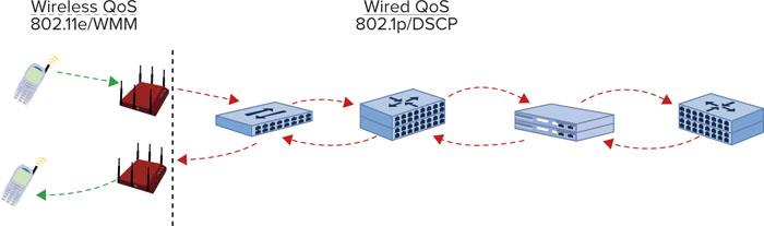
In other words, QoS is an end-to-end endeavor and must be planned as such. One weak link (no QoS or poorly implemented QoS) in the network path can ruin the service quality that network designers work so hard to protect.
It is also important to consider that QoS is dependent on reliable and highly available carrier mediums. There are several places in this book where we discuss the dynamic and unstable nature of the wireless medium, and for good reason. The RF domain is an important foundation on which wireless technologies are built. QoS protocols is not an adequate answer to an unreliable RF domain. If all the proper classification, queuing, and prioritization occur within stations and on the wired network but the wireless domain is unreliable (high collisions/retries, low bandwidth, interference, etc.), QoS won’t be effective for ensuring application performance. For that reason, it is important that wireless designers ensure optimum planning and use of the RF medium so that applications can use the wireless resources effectively and end users can keep smiling. QoS is end to end, or it is nothing at all.
Classifying and Marking
Classifying and marking are two terms related to the way in which packets are identified as needing differentiated treatment across network hops. Classification is generally considered to be the interpretation of QoS settings for incoming packets. Marking is generally considered the designation of QoS parameters for outgoing packets. So, you classify incoming traffic, and you mark (or tag) outgoing traffic.
There are a number of ways to classify QoS data, and these methods largely depend on the medium type of the network, the protocol in use, and the capabilities—and configuration—of the infrastructure equipment. In some cases, application data can be classified on a per-hop basis by some characteristic of the data (i.e., IP addresses, MAC addresses or OUIs, or network service), but it is more common (and often easier) to rely on trusted markings in frame or packet headers as specified by a common MAC- or IP-layer protocol, such as DSCP. After classifying data, appropriate QoS policies can be applied to the data.
Queuing and Scheduling
Queuing and scheduling refer to the way in which classified data is handled and the order in which it is processed for outgoing transmission. In other words, how is priority actually provided? There are several techniques designed to facilitate priority. Among others, these include:
- Scheduled polling
- Weighting mechanisms
- Round-robin
These are generic types of QoS scheduling, and there are many different variations on these types. Data arrives at a station, is classified into a queue, and is then selected from queues in accordance with the scheduling or queuing algorithm or mechanism. A queue is sometimes called a bucket, where frames wait to be processed for transmission by a network node.
In accordance with the network medium type, networking protocols, and QoS method(s) in use, network nodes perform frame and/or packet translation (conversion from one type to another). As a part of translation, stations must take the incoming data classification and convert that classification into an outgoing QoS marking or tag. This translation and conversion process facilitates the end-to-end QoS at each hop in the data’s transmission path. In some cases, translation will convert one type of classification and convert it into another type of marking. In other cases, the same protocol(s) may be in use on the incoming and outgoing interfaces, so the classification translation is a direct transfer.
In the next sections, we will look at the intricate details of WLAN QoS as well as some of the most common wired QoS protocols. As we flesh out the details of these protocols, it will help us to discuss network design practices from a technical perspective.
WLAN Arbitration
If we compare wired and wireless technologies today, it becomes apparent fairly quickly that wired networking technologies generally offer greater capacity and performance than wireless networks. Wireless networks come with many benefits as well—such as mobility and low cost—but their primary drawback is the constraint of a shared wireless medium. As 802.11n has demonstrated, wireless technologies are always improving and capacity is increasing, but resources remain limited.
In this section, we will take a deeper dive into WLAN QoS by looking at the technologies, processes, and protocols that are used on WLANs. The foundational element to this discussion is WLAN arbitration and 802.11 channel access. This is a hefty topic by itself, but we will attempt to truncate it to the most essential components for this treatment and to tease these design applications out in a following section.
Our intention here is not to bog you down with the details but to provide the details that any professional WLAN designer should know. An understanding of 802.11 arbitration is fundamental to proper network design and QoS provisioning.
Channel Access Methods
The 802.11 specification defines a MAC architecture for 802.11 channel access. This architecture includes four different channel access methods that dictate how wireless stations should use the shared wireless medium in a “good neighborly” way.
These channel access methods (or functions) dictate the rules or patterns in which a wireless station can access the wireless medium. Each method has different rules for different network environments. In general, they are designed to facilitate relative “fairness” or to create statistical priority for devices or applications to access the wireless medium. Here’s a description of each:
Distributed Coordination Function (DCF) The Distributed Coordination Function (DCF) is the fundamental, required contention-based access function for all networks. DCF does not support QoS.
Point Coordination Function (PCF) The Point Coordination Function (PCF) is an optional, contention-free function, used for non-QoS STAs. PCF is not currently implemented in the market.
Hybrid Coordination Function (HCF) Enhanced Distributed Channel Access (EDCA) Hybrid Coordination Function (HCF) Enhanced Distributed Channel Access (EDCA) is optional, but it is the method used to provide prioritized contention-based QoS services. EDCA is the way to provide QoS for modern WLANs.
Hybrid Coordination Function (HCF) Controlled Channel Access (HCCA) Hybrid Coordination Function (HCF) Controlled Channel Access (HCCA) is optional, and provides parameterized contention-free QoS services. HCCA is not currently implemented in the market.
Of the four channel access methods, only two (DCF and EDCA) are used today. The other two access methods, PCF and HCCA, have not been implemented by WLAN vendors, so we will avoid discussing these coordination functions here. The MAC channel access architecture is shown in Figure 10.2.
FIGURE 10.2 802.11 MAC architecture

The foundational access method is called Distributed Coordination Function (DCF). In DCF, the coordination function logic is generally the same in every station (STA) in a basic service set (BSS)—except PHY-specific parameters, such as slot times. Stated differently, each station within a DCF follows the same channel access rules. DCF is contention based, which means that each device “competes” with the other devices to gain access to the wireless medium. After contention is won, the STA can transmit a frame, or series of frames, depending on the access rules. Then the contention process resumes. As the original 802.11 network access method, DCF is the most simple channel access method; however, being the first access method, it lacks support for QoS. To maintain support for non-QoS devices in QoS-enabled networks, support for DCF is required in all 802.11 networks.
As an optional access method that may be used in addition to DCF, HCF was introduced to support QoS. HCF EDCA offers prioritized contention-based wireless medium access. In other words, EDCA provides a way to prioritize 802.11 traffic so that certain traffic types are statistically more or less likely to be transmitted first. This is done by classifying 802.11 traffic types by user priorities (UP) and access categories (AC), which are associated with more or less aggressive contention parameters, depending on the desired priority.
A user priority (UP) is a value associated with a medium access control (MAC) service data unit (MSDU) that indicates how the MSDU is to be handled. The UP is assigned to an MSDU in the layers above the MAC. There are eight UPs, and these eight UPs map to four WMM access categories.
An access category (AC) is a label for a set of parameters used by QoS stations to contend for priority access to the medium. There are four ACs.
Contention Mechanisms
Both DCF and EDCA use the same basic contention mechanisms to arbitrate access to the wireless medium. We will look at these mechanisms in greater detail in this section, and we will discuss how differentiated priority is provided within EDCA.
Carrier Sense
To be friendly users of the shared frequency space in which they operate, Wi-Fi devices listen before transmitting. This process of listening is called carrier sense, and as the term implies, it is a way for stations to sense the activity on the medium. There are two modes of carrier sense: physical and virtual. Carrier sense works the same way with all channel access mechanisms.
Physical Carrier Sense—CCA There are actually two subtypes of Clear Channel Assessment (CCA)—carrier sense (CS) and energy detect (ED):
Carrier Sense (CS) The first type is simply called carrier sense (CS). CCA’s CS mechanism is used to monitor the RF domain for incoming WLAN traffic. In other words, when a STA is not transmitting, its receiver is always listening and ready to process modulated WLAN frames, beginning with the PHY preamble (the start of a WLAN frame). If a STA detects an incoming WLAN frame at an RF amplitude above its CCA CS threshold, the STA will identify the RF medium as “busy” and it will not contend for the medium or transmit a frame. If there are no incoming frames or the amplitude of an incoming frame is lower than the CCA CS threshold, the STA will perceive the wireless medium as “idle” and continue to freely contend for the medium and transmit frames if it wins contention.
Energy Detect (ED) The second type of CCA is called energy detect (ED). ED is similar to CCA CS, but instead of listening for WLAN frames, the ED busy/idle state is dependent on raw RF energy. For ED to indicate a “busy” medium, the RF energy on the wireless channel must be pretty substantial.
With either method (CS or ED), a “busy” medium will prevent the STA from attempting to win contention. During a busy medium, WLAN stations sit quietly and wait to begin “contending” again. As you can see, CCA is a bit like a permission slip for WLAN transmissions. When the medium is idle, STAs can contend and transmit frames. If the medium is busy, they must wait. CCA is a critical aspect of WLAN arbitration.
Physical Carrier Sense Threshold Values
As an example of the CCA thresholds for a specific PHY, let’s look at 802.11a details in Clause 17.2.10.5 (CCA sensitivity) of the 802.11-2007 specification:
CCA CS CCA indicates a busy medium when the start of a valid OFDM transmission is received at a level equal to or greater than the minimum modulation and coding rate sensitivity (−82 dBm).
CCA ED If the PHY preamble of the frame is missed, the CCA holds a busy medium for any signal 20 dB above the minimum modulation and coding rate sensitivity, which equates to −62 dBm.
Clause 17’s CCA sensitivity is much higher (meaning the signal can be lower power) when the frame header is received and processed correctly. The sensitivity threshold for RF noise, including 802.11 frames whose header was not processed, as well as non-802.11 RF sources, is much lower, at −62 dBm. Thus, it takes a much stronger signal to indicate a busy medium when CCA ED is used instead of CCA CS.
A real-world example of this would be if an 802.11b/g/n client station were attempting to transmit a frame and a microwave oven in the area caused the 802.11 station to indicate a “busy” medium and cease transmitting. That is, if the microwave oven’s amplitude was measured by the wireless station at a level above its ED threshold, the station would not be able to transmit on the affected channel.
Virtual Carrier Sense—Network Allocation Vector (NAV) In addition to the physical carrier sense mechanisms, the 802.11 specification also defines a virtual carrier sense. Within the MAC header of WLAN frames is a field called the Duration field. This field carries a value that is used to indicate the duration of time before STAs can contend for the wireless medium again. To be completely accurate, the duration value covers the interframe space (required quiet period) after the frame in which it resides, as well as all remaining frames and interframe spaces that are a part of the current frame exchange or transmission opportunity. Figure 10.3 shows a simple frame exchange and the values that are used by the STA to virtually identify the busy/idle state of the wireless medium.
FIGURE 10.3 Purpose and location of the Duration field
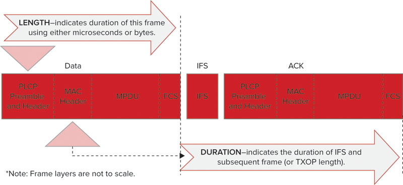
When STAs process the Duration value, they set a network allocation vector (NAV) timer, and count down that timer until the duration value reaches zero. The NAV timer must equal zero for a STA to contend for the wireless medium and transmit a frame. The NAV timer is used in concert with the CCA to inform the STA of the status of the wireless medium, whether busy or idle.
Interframe Spacing
Interframe spaces are an important part of channel access rules that dictate when a STA can access the medium, or when they can begin contending for access. After a frame has been transmitted on the wireless medium, there must be a short idle period before another frame may be transmitted by any station. This idle period is called an interframe space (IFS) and is measured in microseconds (μs). Interframe spaces are used to provide granular controlled access to the wireless medium. For example, some frames must be immediately acknowledged. Thus, before an ACK frame is transmitted, a short IFS (SIFS) is observed by the transmitter. This ensures that the ACK frame takes priority over other frames, which require longer IFS intervals before transmission.
The length of an IFS depends on the frame being transmitted and the access method in use. There are six types of IFS:
- Short interframe space (SIFS)
- PCF interframe space (PIFS)
- DCF interframe space (DIFS)
- Arbitration interframe space (AIFS)
- Extended interframe space (EIFS)
- Reduced interframe space (RIFS)
For our discussion here, we will only look at three of the interframe spaces: SIFS, DIFS, and AIFS.
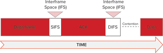
The basic concept of an IFS is shown in Figure 10.4, which shows a data frame, SIFS, and ACK. Following the ACK frame, a DIFS would be observed (assuming DCF); then contention would continue until the next station transmits a frame.
FIGURE 10.4 The basic concept of an interframe space
SHORT INTERFRAME SPACE (SIFS)
SIFS are used within both DCF and EDCA. For 802.11-2007, SIFS is the shortest of the IFS values and is used prior to ACK and clear to send (CTS) frames. However, with 802.11n, a shorter IFS (RIFS, which we will not discuss here) was introduced. The purpose of SIFS is for stations to maintain control of the wireless medium during a frame exchange sequence that warrants priority. By using SIFS, which is a small amount of time, no other stations (which would use other, longer IFS) will be able to win contention and disturb an ongoing exchange.
In other words, SIFS is used as a priority interframe space once a frame exchange sequence has begun. It allows the participants of a frame exchange sequence to complete their conversation uninterrupted. This is true when multiple frames are transmitted within a transmission opportunity (TXOP) (as with frame bursting), and it is also true when a single frame is transmitted (as with typical Data-ACK exchanges).
DCF INTERFRAME SPACE (DIFS)
When a STA desires to transmit a data frame (MAC protocol data unit, or MPDU) or management frame (MMPDU) for the first time (not a retry) within a DCF network, the duration of a DIFS must be observed after the previous frame’s completion. As the IFS for DCF, a DIFS does not provide QoS differentiation. To provide relative equality in channel contention, DIFS values are the same for all STAs with similar PHY capabilities. The DIFS values are shown in Table 10.2.
TABLE 10.2 Calculations for IFS Values

ARBITRATION INTERFRAME SPACE (AIFS)
With EDCA, the basic contention logic is the same as with non-QoS networks, but in order to facilitate QoS differentiation, some notable differences are provided. While DCF designates a single DIFS value for each PHY to use for contention, as shown in Table 10.2, EDCA establishes unique IFS durations for each AC within a BSS. These unique IFS values are called AIFS, and because an AIFS is unique for each AC, an AIFS is notated as an AIFS[AC]. QoS STAs’ TXOPs are obtained for a specific AC, so each STA is simultaneously contending for medium access with multiple ACs. An AIFS interval is used by QoS stations when attempting to transmit data frames, management frames, and some control frames.
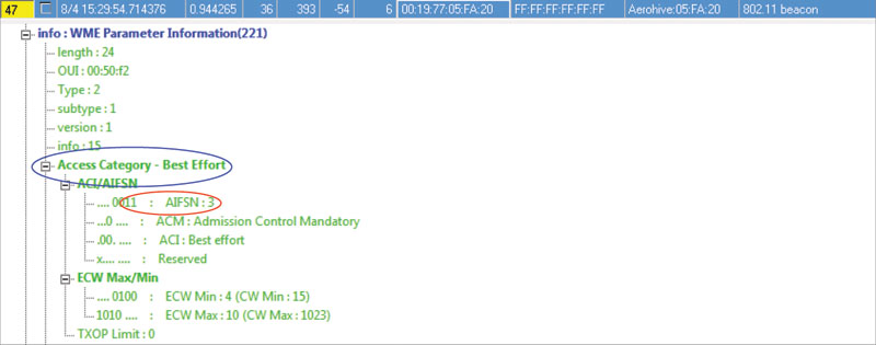
For improved control of QoS mechanisms, AIFS values are user-configurable. By default, QoS APs announce an EDCA parameter set in the Beacon frame that notifies stations in the BSS about these QoS values. When you change these values in the AP configuration, the AP will broadcast a different set of parameters to the BSS. These parameters have a direct impact on the amount of priority given to a specific AC.
Figure 10.5 shows a Beacon frame that includes the AIFSN value for the Best Effort AC. As in the figure, these values can be found for each AC in the EDCA Parameter Set Element within a Beacon frame. In Figure 10.5, a highlight shows that this is the best-effort AC and the second highlight shows that the AIFSN is currently set to 3, the default setting. The AIFSN value determines the duration of the AIFS[AC], as we will discuss next.
FIGURE 10.5 Default AIFSN value as seen in a Beacon frame
As a quick disclaimer, some of the calculations related to IFS values can be a bit intimidating at first. Other materials are available for the same topic, and we highly recommend that you look at these topics in greater depth.
![]()
For a more thorough and in-depth treatment of this topic, refer to the whitepaper titled “802.11 Arbitration,” authored by Marcus Burton, which is available at http://www.cwnp.com/pdf/802.11_arbitration.pdf.
An AIFSN is a number (AIFS number) value that is user-configurable and determines the brevity (or length) of an AIFS interval. AIFSN values are set for each access category, giving the AIFS[AC] a shorter or longer duration, in accordance with the desired priority of the AC. This is demonstrated by the formula used to calculate an AIFS[AC]:
AIFS[AC] = AIFSN[AC] × aSlotTime + aSIFSTime
These calculations can be made using the Slot Time and SIFS values from Table 10.2. The default values for each AIFSN[AC] are shown in Table 10.3 along with the resulting AIFS[AC] value for each PHY. By modifying the AIFSN[AC] shown in Table 10.3, administrators can manipulate the AIFS[AC] duration.
TABLE 10.3 Default AIFS Parameter Set

In comparison with Table 10.2, which shows the fixed SIFS and DIFS values, you can see in Table 10.3 that AIFS values are always longer than a SIFS for a given PHY. This ensures that SIFS-separated frame exchanges take priority.
Although much of this discussion about IFS has been academic, understanding these principles is relevant to network design. Figure 10.6 shows how the IFS values differ, and how a change in these values is directly related to a device’s ability to win contention and transmit frames.
FIGURE 10.6 Relationship of interframe spaces in contention framework

Backoff Timers
The concept of a backoff timer is fairly complex, and we will avoid all of the intricate details for this discussion. Instead, we will focus on the simple purpose of a backoff timer, some basics on its functionality, and how it is relevant to network design.
A random backoff timer is a way to add randomness to the 802.11 contention process to minimize collisions between competing stations. The backoff timer is a value that is randomly selected from a range of values called the contention window (CW). The CW is based on EDCA parameters specified by the 802.11 standard and are user-configurable for QoS control. Here’s how it works.
A STA randomly selects a backoff value from the CW. The backoff value represents the number of slot times (we will discuss this value in the next section) that must be observed with the wireless medium remaining idle before a STA can transmit a frame. So, if a STA selects a random backoff value of 7, it must wait seven slot times. The size of the CW varies in accordance with the PHY technology in use on a STA as well as the AC for QoS STAs. As you might guess, higher-priority ACs have smaller CWs, which gives them a higher probability of selecting a lower backoff value. For example, if you have a voice AC with a CW from 0–7 and you have a best-effort AC with a CW from 0–31, the voice AC is far more likely to select a lower backoff value than the best-effort AC. Lower backoff values represent a greater likelihood to win contention and transmit a frame.
The lower range of the CW is always 0. The upper range of the CW is based on one of two values: the CWmin and the CWmax. For the first attempt at a frame transmission, the CWmin value is used as the upper limit of the CW. For example, if the CWmin is 15, the CW for the first attempt at a frame transmission would be 0–15. If a collision occurs and a frame must be retransmitted, the upper limit of the CW increases exponentially for each retry until this value reaches the CWmax, as shown in Figure 10.7. In other words, collisions and retries are bad. Collisions require that STAs wait longer (statistically) for each subsequent attempt at a frame transmission. This helps us to see why high retry rates in latency-sensitive environments can be problematic for application performance.
FIGURE 10.7 Relationship between retries and a CWmax

Just to reiterate, the CW is the range of values from which a STA randomly chooses a backoff value. This backoff value is equal to the number of slot times the transmission medium must be idle before the STA can transmit a frame.
So, as we mentioned in passing before, the CW represents a statistical probability for priority. ACs or STAs with lower CW values are more likely to select lower backoff timers, and thus, win contention more frequently. Higher-priority ACs, such as for voice and video, have small CWs. To make this concept more tangible, the CW parameters are shown in Table 10.4 for an 802.11n STA using default EDCA parameters.
TABLE 10.4 802.11n STA Default Contention Window Values

As you can see from Table 10.4, AC_VO and AC_VI have a significantly higher priority than AC_BE and AC_BK due to a lower AIFSN[AC] and smaller CWmin and CWmax values. As this plays out in the arbitration process, high-priority ACs are far more likely to win contention than low-priority ACs and STAs.
Slot Times
As we discussed previously, a slot time is a PHY-specific time value, measured in microseconds (μs), that is used as a part of the arbitration process. Specifically, the random backoff value reflects the number of slot times that must be observed before a frame may be transmitted. So, a lower slot time reflects a contention advantage over other devices with higher slot times. Refer to Table 10.2 to see the slot times for each PHY. As you can see from Table 10.2, legacy PHYs have higher slot times than modern PHYs.
Implications for WLAN Design
Let’s now look at some of the ways in which we can apply this knowledge at a high level:
Contention Domains and Probabilistic Contention The first obvious fact about wireless networks is that they operate within a shared contention domain. Contention domains can be segmented—generally speaking—by isolating devices physically, by using nonoverlapping channels, and by shaping RF propagation with antennas and transmit power configurations. Operating within the constraints of 802.11 arbitration, we must use these controllable design elements to maximize capacity and minimize contention within the RF domain. As the number of devices within a contention domain increases, collisions will inevitably increase. Of course, a modest number of collisions and retries is acceptable and normal, but in excess, collisions and retries can bring application performance to unacceptable levels.
Standardized WLAN arbitration is probabilistic. This means that QoS only provides a statistical advantage for some devices to access the network; it does not provide a guaranteed priority. Based on that knowledge, you should approach network design by assessing the load that will be placed on your network and the mission-criticality of sensitive applications. If voice is the most important application on your WLAN, you may want to consider taking extra steps toward isolating VoWiFi to its own contention domain or ensuring that the statistical priority is sufficient for application performance requirements. Many experts in the field recommend deploying latency-sensitive applications like voice in an entirely different frequency band than data. This is an option, but it may lead to other problems, such as what to do with devices that are both data and voice devices (such as smartphones and laptops with softphones). Similarly, the advances of 802.11n in 5 GHz are most beneficial to data applications, whereas voice applications enjoy only a modest benefit. Further, if you prioritize voice applications by supporting them in 5 GHz, your data applications will likely see a performance impact if they are relegated to 2.4 GHz. If there is a clear priority for one application over another, this may be a viable option, but in most cases, several applications are mission-critical, which prevents complete isolation of contention domains by application.
SSIDs and Contention Domains As you assess the options for segmenting applications into different contention domains, remember that SSIDs do not divide a network into different RF domains. All SSIDs supported on a radio operate within the same contention domain. SSIDs are one way to control the access rules by which client devices compete for the medium (such as by preventing certain access categories, or by supporting proprietary access control mechanisms like airtime fairness), but SSID “segmentation” has limited benefit to wireless contention.
Customizing EDCA Parameter Sets While the standardized set of EDCA parameters is usually sufficient for WLAN QoS, some networks may require fine-tuning of these parameters. Thankfully, most WLAN infrastructure vendors allow administrators to change these settings, so you can provide greater differentiation between low- and high-priority access categories.
Channel Capacity and User Density Designers should also consider AP-to-client load expectations with arbitration in mind. When there is a high number of high-priority devices (such as VoWiFi phones), designers may do well to attempt to minimize the load on each AP by decreasing AP coverage areas, performing load balancing, or using other load management practices. The traffic patterns of some low-latency, high-priority applications can be somewhat demanding when there are high user densities. This is often because these applications must transmit frames frequently, and they observe short contention periods. For this reason, a fewer number of devices can typically be supported by a single AP. When CWs range from 0–3 (default for AC_VO) and devices are attempting to access the medium frequently, the statistical likelihood of two devices transmitting at the same time increases dramatically. This may lead to a significant number of collisions when client density is too high. For this reason, WLAN voice client vendors typically have a recommended maximum client density for each AP.
WLAN QoS: WMM and 802.11e
The WLAN QoS mechanisms described in the previous section and later sections were introduced to 802.11 WLANs by the 802.11e amendment, which is now a part of 802.11-2007. However, in the real world, only a subset of 802.11e functionality has been implemented by vendors. The Wi-Fi Alliance introduced a specification based on 802.11e QoS, called Wi-Fi Multimedia (WMM). WMM represents the functionality we see in the real-world implementations.
The Wi-Fi Alliance’s WMM knowledgebase can be found at www.wi-fi.org/knowledge_center/wmm. Some of this content requires a Wi-Fi Alliance membership.
As a subset of 802.11e, WMM makes implementation of WLAN QoS easier for infrastructure and client vendors. As with other Wi-Fi Alliance specifications, a certification program is in place to validate device compliance with WMM functionality. Device certification is an important insurance for device selection and planning of QoS-enabled WLANs. Today, all 802.11n certified devices support WMM.
In the wireless domain, WMM is a feature that should be supported by both the AP and the client for maximum effectiveness; however, WMM does not have to be supported by both. In a QoS BSS, non-QoS traffic is assigned best effort (AC_BE) priority. Most WLAN vendors’ APs can still perform downstream QoS, even if the recipient client does not support WMM. Remember, 802.11 QoS is largely designed to provide prioritized access to the transmission medium, so even if QoS is only downlink, it will still be helpful for some applications. If an application requires bidirectional prioritization, as with most voice implementations, performance will suffer if the client does not support WMM. Applications like unidirectional video will not be as noticeably impacted if WMM is only supported on the downlink. For WMM admission control, WMM is mandatory on both the client and the AP. Similarly, there are many facets to WMM that are lost when both the client and the AP do not support WMM.
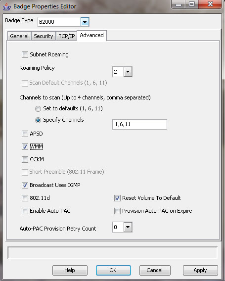
In many client devices supporting WMM, very few configuration parameters are provided. In some cases, there aren’t any client configuration variables. In others, configuration is limited to enabling or disabling WMM, as is shown in the Vocera badge configuration utility in Figure 10.8. In that regard, the client application and software driver dictate the operation of a specific NIC.
FIGURE 10.8 WMM configuration options for Vocera VoWiFi badges
There are many important aspects to WMM operation, so we will explore them in the following sections.
WMM QoS Classification
In our introduction to QoS in the WLAN arbitration section, we mentioned that there are eight user priorities (UPs) and four access categories (ACs). As data is passed from an application down the protocol stack within a STA, it is classified with a UP in accordance with the coding of the application. This UP is passed to the MAC layer for classification and queuing.
Because of the relationship between WLANs and Ethernet LANs, WMM classification is correlated with 802.1p (now part of 802.1D) UPs. We will look briefly at 802.1p UPs later in the section entitled “QoS in Wired Networks.” In WMM, these UP classifications are mapped to four ACs, which possess their own queues and access parameters. The UP to AC mapping and naming conventions are shown in Table 10.5. To preserve the UP value for a frame when it is translated to different media types, WMM stations also include the UP (which is more granular than the AC) in the QoS Control field of transmitted QoS frames—802.11 management frames do not include the QoS Control field, so they are treated with AC_VO access parameters on the wireless medium, and they are not forwarded to the wired interface. The QoS Control field enables the receiving STA (usually an AP) to read the UP classification and then properly mark the frame when it is translated and transmitted onto the wired medium.
TABLE 10.5 Relationship Between 802.11 Access Categories and 802.1p User Priorities

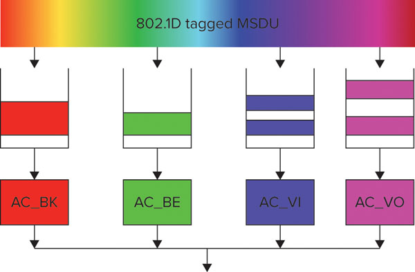
Each of the four ACs specified by WMM has its own contention parameters and frame queues. The intra-station contention and queuing concept is shown in Figure 10.9.
FIGURE 10.9 WMM queuing within a STA
Admission Control and Traffic Streams
Admission control is a configurable option in which stations must request permission prior to using an AC. Support for admission control is indicated by use of an “admission control mandatory” bit, so you will often see the abbreviation ACM referring to admission control. In busy network environments, when too many users are attempting to access the network resources at the same time, quality will suffer for everyone. The purpose of admission control is for the AP to maintain control of the use of network resources so as to preserve application quality for the maximum number of stations. Clients must check in with the AP to see if an acceptable amount of resources are available. The AP’s admission control algorithms are vendor specific and are dependent on channel capacity, RF link conditions, network performance indicators (errors, retransmissions, etc.), and other criteria. Some user-defined admission control parameters are also commonly used, such as the number of permitted calls and maximum bandwidth allocation; these configuration elements are shown for a Cisco 5508 WLAN controller in Figure 10.10. Figure 10.11 shows a Beacon frame with admission control disabled for all ACs.
FIGURE 10.10 Cisco admission control settings for voice traffic
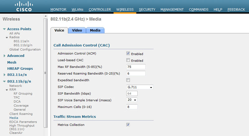
FIGURE 10.11 Admission Control disabled for all ACs

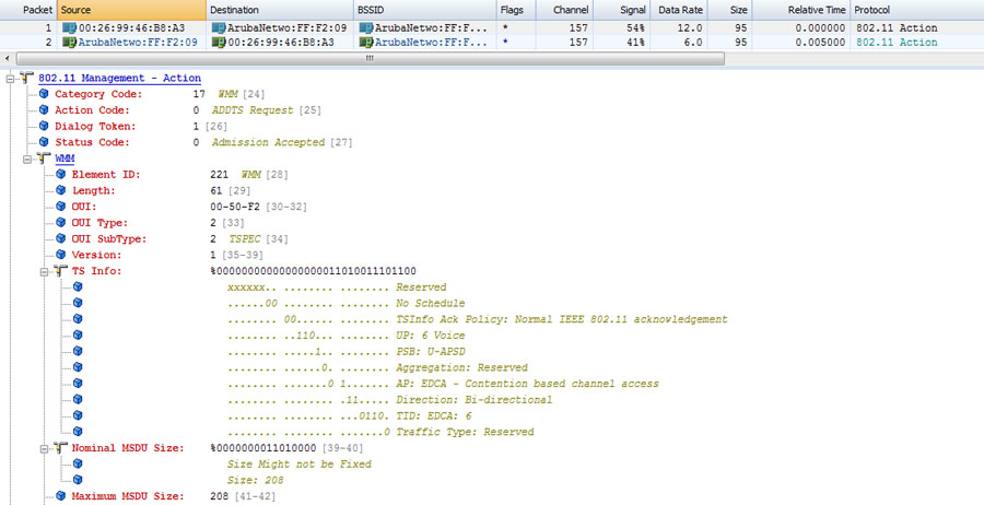
If admission control is enabled, associated clients seek the AP’s permission to use a network resource by sending an ADDTS (short for Add Traffic Stream) Request Action frame to the AP. ADDTS frames are designed to create new traffic streams (TSs) with custom service parameters. Within an ADDTS is a TSPEC (short for Traffic Specification) element, which is a set of parameters that classify the performance requirements of a traffic stream. A sample ADDTS Request frame is shown in Figure 10.12.
FIGURE 10.12 ADDTS Request frame
The AP processes the ADDTS Request (by using the information in the TSPEC element), compares it with the admission control algorithms, and either accepts, rejects, or modifies the TSPEC information. The AP’s response is sent in an ADDTS Response frame, which informs the client how to proceed. A sample ADDTS Response frame is shown in Figure 10.13. If clients are joining a BSS, a TSPEC can be established by means of a TSPEC element in (re)association request frames. The AP’s response to the TSPEC comes in the (re)association response frame. The details of admission control processes are beyond the scope of the CWDP exam, but proper design always requires that designers understand the technology and processes that underlie the deployment.
FIGURE 10.13 ADDTS Response frame

Even when admission control is not required, traffic streams with custom TSPEC parameters may still be established. If the upper layers of a STA determine that a set of frames requires some specific treatment beyond the basic set of contention parameters defined for an AC, the upper layers can indicate this requirement in the instructions to the MAC. The STA then follows the same steps described in the previous paragraph to set up a TSPEC to meet the traffic stream’s performance requirements.
Identifying Traffic for Prioritization
When the upper layers of a station have data to send, they send the data down the protocol stack with instructions to the MAC layer with information about the data to be transmitted. In the instructions from the Logical Link Control (LLC) to the MAC, each MSDU includes a traffic identifier (TID), as determined by the upper layers. The TID indicates the type of treatment desired for a specific MSDU. TID values range from 0–15; however, only TID values 0–7 are currently used with EDCA. TID values 8–15 correspond with HCCA (or HEMM) traffic streams. The information sent from the upper layers also indicates whether additional prioritization measures are required for the set of MSDUs. These additional measures would call for a unique set of traffic requirements, as defined within a TSPEC.
Assigning QoS Policies
Within a typical WLAN infrastructure, QoS policies may define traffic classifications, admission control parameters, bandwidth contracts, scheduling policies, and more. These QoS policies are then tied either to SSIDs for ESS-wide QoS policy enforcement or to groups and users for more granular QoS. AAA attributes, or other user-based authentication methods, are typically used to assign a QoS profile to a user or group. As you plan your method of QoS application, realize that user-based QoS is far more granular and allows for more differentiated services within a service set. However, applying QoS directly to a WLAN profile (SSID) may reflect an easier administrative approach. The decision ultimately comes down to the way in which you are dividing your traffic and service types up within the WLAN profiles.
QoS in Wired Networks
After all of our discussion about WLAN QoS, we must remember that WLAN QoS is useless if it isn’t translated to the wired network. For that reason, if we’re to understand wireless QoS, we must also understand at least the basics of wired QoS.
In general, WLANs are an extension of 802.3 Ethernet LANs that support the IP protocol at Layer 3. With that in mind, we will provide a quick overview of the predominant QoS protocols and considerations that are relevant to those medium types.
The Difference Between Wired and Wireless QoS
We should point out one significant difference between wired and wireless QoS. It is a common practice in wired network design to gratuitously overprovision networks so that there are enough resources to accommodate the expected traffic load without stressing the network’s capacity. In any network with sufficient resources, throughput, latency, jitter, and loss requirements are likely to be met for most applications if the network is not being overly taxed. In practice, overprovisioning usually adds cost to a network deployment and is embraced as a tactic to avoid the complexities of configuring systemwide QoS. Unfortunately, overprovisioning is not an option with WLANs, as bandwidth is limited by virtue of a crowded, shared contention domain; therefore, end users are forced to use the available resources with utmost discrimination. That discrimination leads us to the necessity of QoS.
802.1D, 802.1Q, and 802.1p Standards
802.11 WLANs may be deployed into many different types of wired networks, and the overwhelming majority of deployments are as an extension of 802.3 Ethernet LANs. End-to-end QoS implementations are heavily dependent on compatibility of standardized QoS protocols between different media types, so the IEEE 802.1 working group specifies standards that are intended to facilitate compatibility between different 802.x mediums, such as 802.11 and 802.3. 802.x standards are primarily MAC-layer protocols, and these protocols are an important part of QoS homogeneity across an enterprise. For the wired QoS discussion with Ethernet, 802.1p UPs are our primary topic of interest, but we should briefly discuss 802.1D and 802.1Q before looking specifically at 802.1p.
802.1D The 802.1D standard defines IEEE MAC bridging. The original 802.1D standard did not specify a way for bridged networks to signal user priority within a frame, so 802.1p was specified as an addition to 802.1D for that purpose.
802.1Q 802.1Q is a standard that defines virtual LANs within the context of the bridging framework defined by 802.1D. At this point, you may be asking what VLANs have to do with QoS. The answer is that they don’t really have much to do with QoS, but 802.1Q modifies MAC frame formats in such a way that 802.1p user priorities can be included in the modified frames. 802.1Q provides VLAN support by extending the MAC header of 802 frames with a 4-byte (32-bit) field, which includes a VLAN identifier. 802.1p was developed separately from 802.1Q, but 802.1p is used as a part of 802.1Q frame expansion. Specifically, 3 of the 32 bits that are added to an 802.1Q-expanded frame are used for the 802.1p user priority, also known as a priority code point (PCP). For a reference, the 802.1Q expansion field is shown in Figure 10.14.
FIGURE 10.14 802.1Q frame expansion
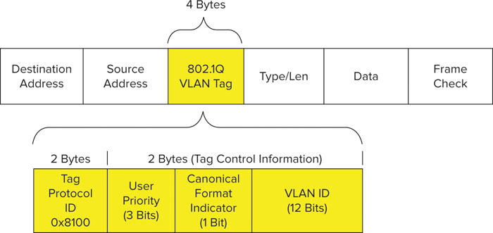
802.1p As you can see in Figure 10.14, the PCP (User Priority, in the figure) subfield is 3 bits in length, which accommodates values from 0 to 7. The eight PCP subfield values are 802.1p UPs, and correspond to different classes of service (CoSs), which are also known as traffic categories. These eight UPs are shown in Table 10.6 with their corresponding traffic type. As we discussed earlier, these eight UPs are mapped to 802.11 AC classifications.
TABLE 10.6 802.1p User Priority Classifications
| User Priority | Acronym | Traffic Type |
| 1 | BK | Background |
| 2 | -- | Spare |
| 0 (Default) | BE | Best Effort |
| 3 | EE | Excellent Effort |
| 4 | CL | Controlled Load |
| 5 | VI | Video |
| 6 | VO | Voice |
| 7 | NC | Network Control |
IEEE Std 802.11-2007, Copyright 2007 IEEE. All rights reserved.
Keeping 802.x Standards Organized
It can be a challenge to keep the myriad 802.x standards organized. The numbering and lettering formats can get confusing. While we don’t have a quick and easy way to keep it all organized, repetition may be helpful. As it relates to 802.x standards, let’s review:
802.1D Specifies IEEE MAC Bridging. 802.1p was added to the 802.1D standard.
802.1Q A standard that defines virtual LANs within the framework of the 802.1D Bridging standard.
802.1p Defines eight UPs, which are signaled in a 3-bit priority field that is a part of 802.1Q-tagged Ethernet frames. Despite its relationship to 802.1Q, 802.1p was written as an addition to the 802.1D standard, and was rolled into 802.1D in 1998.
802.3ac An amendment to the Ethernet (802.3) working group that expanded the maximum frame size from 1518 to 1522 bytes. This change accommodates the 4 additional bytes from 802.1Q expansion, which includes the 3-bit PCP (802.1p) CoS field.
802.11e An amendment to the 802.11 standard; defines QoS for WLANs. 802.11e was rolled into 802.11-2007.
DiffServ Protocols
All of the QoS protocols we’ve discussed thus far have been MAC-layer protocols. At the network layer, DiffServ is the primary QoS mechanism used in today’s IP-based networks. To meet the needs of a highly divergent set of IP networks, DiffServ is a highly flexible QoS mechanism.
DiffServ Resources
The IETF defines DiffServ and provides additional help in a number of RFCs, as the following list shows. A simple Internet search will also yield a number of informative articles and links about DiffServ.
RFC 2474 Definition of the Differentiated Services field (DS field) in the IPv4 and IPv6 headers
RFC 2475 An architecture for Differentiated Services
RFC 2597 An assured forwarding PHB group
RFC 3140 Per-hop behavior identification codes (obsoletes RFC 2836)
RFC 3246 An expedited forwarding PHB (obsoletes RFC 2598)
RFC 3260 New terminology and clarifications for DiffServ
RFC 4594 Configuration guidelines for DiffServ service classes
DiffServ classification can be performed in a number of ways, including the IP source or destination address, the network service, or more commonly, Differentiated Services Code Point (DSCP) bits in the IP packet header. Classification results in an assignment of each packet to a traffic class, which is associated with policies that determine the services provided to that traffic class. The frame handling policies for a traffic class are referred to as per-hop behaviors (PHBs). The IETF provides recommended PHBs for each traffic class and DiffServ is designed to be highly flexible and granular, so network designers may also apply other traffic engineering policies, such as rate limiting and traffic shaping, to IP traffic.
Within an IPv4 packet header, there is an 8-bit differentiated services field. Six of these bits are the DSCP values used for classification, which provides a total of up to 64 different traffic classes. Half of the DSCP values are designated for specific services, but the other half are open for user-defined services.
Each implementation is tailored to the needs of a specific network, which makes its relationship to wireless networks slightly more flexible and fluid. In other words, the DSCP policies that are applied at the network layer do not have a fixed correlation to the policies on the 802.11 MAC. Whereas 802.1p and WMM share a common mapping of 3-bit UP values, DSCP and WMM do not share a consistent one-to-one priority mapping for all networks. However, the IETF does provide fairly extensive documentation and deployment recommendations for DSCP traffic classes, services, and code-point assignments, and these recommendations pave the way for a reasonable amount of consistency across different networks. This allows WLAN vendors to use some consistent UP-to-DSCP conversion.
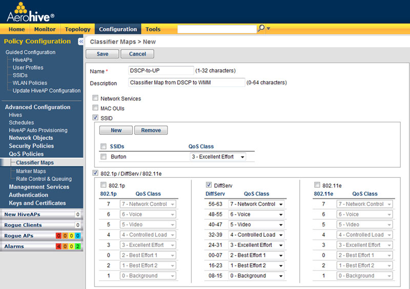
Instead of using 1:1 UP to DSCP conversions—because there are so many DSCP traffic classes—UP to DSCP classifier maps may translate a range of DSCP values to a single UP value for 802.1p or WMM. For example, DSCP values 40–47 may all be mapped to a UP value of 5 (which maps to WMM AC_VI), and vice versa. To demonstrate how this might look in an actual implementation, Table 10.7 shows Cisco’s suggested DSCP to 802.1p and 802.11e UP baseline conversion maps, and Figure 10.15 shows Aerohive Networks’ default classifier map policy, which maps DSCP ranges to UP values.
TABLE 10.7 Cisco’s Suggested DSCP Conversion Map
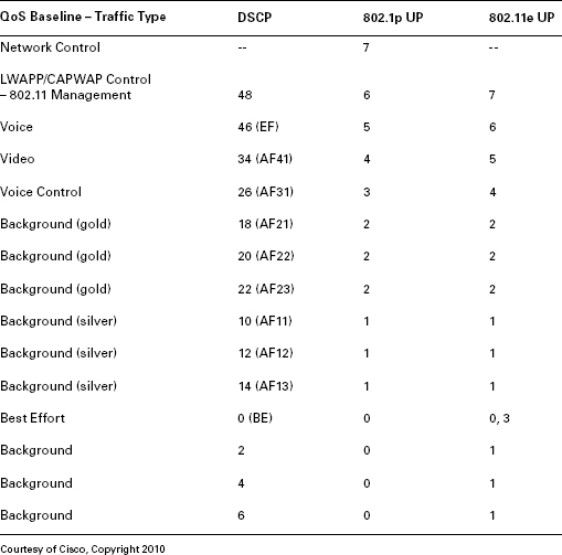
FIGURE 10.15 Classifier map configuration menu
Network Control Priority
You may notice from Table 10.7 that Cisco’s baseline QoS mapping reserves the highest priority 802.1p value for Network control. This traffic type is necessary for maintaining functionality and availability of network resources, so it takes precedence over all types of user traffic. For that reason, it is assigned the highest priority and all other services (such as voice and video) are assigned the next lower priority class to accommodate. This illustrates that vendor-specific design practices are an important part of network design, as is integration of the WLAN into the wired LAN.
Integrating WLANs into Wired Networks
There are several considerations to make as you design the wireless network’s integration with the wired network. Many are architectural in nature and relate to translation of frame markings from one protocol or OSI layer to another. Also, many others are related to integrating with existing wired QoS practices and configuring QoS trust on infrastructure devices.
There are two primary models for data forwarding at the AP: distributed and centralized. When distributed forwarding is employed, APs must have sufficient processing and memory capacity to apply sophisticated QoS scheduling and queuing policies to each frame. This was previously a limitation for some deployments because of underpowered APs. Today, many vendors are moving intelligence into the AP to accommodate this need. QoS configuration on the WLAN will largely depend on the QoS policy on the wired LAN. Some WLAN infrastructure vendors provide granular control of classification and marking maps. In other cases, these maps are fixed and are based on common mappings. If these maps don’t coincide with the desired QoS policy for the network, the wired infrastructure will have to be configured to reclassify traffic that originated from the WLAN or is destined for the WLAN. Let’s look more closely at QoS design considerations for distributed and centralized forwarding models.
Distributed Forwarding One of the first design practices for QoS in distributed forwarding situations is to ensure that the AP is configured to translate between WMM (L2) and 802.1p (L2) and DSCP (L3). In addition to this, the AP’s Ethernet switch must be configured to support and honor the same QoS priority sent by the AP. If the network is using 802.1p CoS bits to provide QoS at the MAC layer, the switch should be configured with appropriate L2 trust and 802.1Q should be enabled on the switch port. On the other hand, if network layer QoS (DSCP) is preferred, the switch should be honoring the DSCP values provided by the AP, and 802.1Q becomes arbitrary for QoS. Depending on the systemwide approach to QoS, the network infrastructure may be applying its own QoS classification policies aside from, or in addition to, code-point values, which may mean that the DSCP values are ignored or changed in favor of new markings. These QoS actions are likely already defined within the company by routing and switching policies, and the primary responsibility of the WLAN is to get the WMM classifications translated to 802.1p and/or DSCP. The wired infrastructure will do the rest.
When a WLAN client constructs an MPDU, the DSCP values are marked in the IP header, encapsulated into an 802.11 header, and passed to the AP. In normal L2 operations, the AP does not inspect DSCP values sent from the wireless client. Thus, in a distributed forwarding model, when the AP forwards the frame on to the wired network, the original DSCP markings from the 802.11 client remain intact.
Centralized Forwarding However, in a centralized forwarding model (frames are forwarded through the WLAN controller), the AP encapsulates the original 802.11 MPDU with new IP and Ethernet headers (with L3 tunneling to the WLAN controller) and marks the new headers in accordance with values derived from the MAC header of the 802.11 frame and the AP’s QoS translation table. In other words, the AP takes the UP from the 802.11 frame, and converts it into 802.1p for the new MAC header and DSCP for the new IP header (assuming 802.1p is marked on the new MAC header, which it may not be). Then these encapsulated frames are sent through the network to the WLAN controller. The original DSCP markings from the wireless client are left intact. When L3 tunneling is used between the AP and WLAN controller, DSCP classification is favored and 802.1p may not be marked at all.
When the WLAN controller receives these encapsulated packets, the outer L2 and L3 headers are removed and the original 802.11 frame is handled by the WLAN controller. In accordance with the QoS policy for that frame, the WLAN controller will apply the appropriate 802.1p and/or DSCP markings on the outgoing frame if it is not destined to return to the AP.
If a frame is destined to go from the WLAN controller to the AP, the controller will encapsulate that frame with an outer MAC and IP header (again, if L3 tunneling is used), marking 802.1p and/or DSCP on the outer headers for proper handling through the network to the AP.
When a centralized forwarding model is used, the network switch to which the WLAN controller is connected must also be properly configured to handle QoS tags from the WLAN controller. This switch port, or combination of switch ports, must be designated with QoS trust in accordance with the desired L2 or L3 QoS policy for the network. If the WLAN controller marks 802.1p and DSCP, the switch may only use 802.1p (CoS trust), or it may strip off and ignore the MAC header CoS bits and rely on the WLAN controller’s DSCP markings. Yet another option is that the Ethernet switch would reclassify the traffic and mark it with new QoS tags to comply with the rest of the wired network configuration.
QoS Challenges
It is difficult to cover the full scope of challenges that may arise with Wi-Fi QoS, but here is a short list of the most high-level headaches:
RF is an unstable and dynamic medium. First, the RF medium is inherently unstable and dynamic. New RF obstructions are introduced and removed. RF interference comes on and goes off. New office partitions are built, removed, or otherwise modified. Doors open and close. Furniture is rearranged. The RF environment is the foundation on which upper-layer protocols and mechanisms, like QoS, are built. If the RF environment is unstable or unreliable, upper-layer features that are built on it will also be unreliable. Stability at this level will generally improve application performance.
Users are mobile and user populations are dynamic. Similarly, users are mobile and are constantly moving throughout a service set. Laptops and other Wi-Fi devices are coming and going, being turned on and off. Legacy devices—with legacy PHYs or no QoS support—join and leave. Neighboring networks are installed, removed, or modified. For many reasons, data rates are always changing. All of these changes affect network capacity and contention.
WLAN QoS is largely probabilistic. We’ve already mentioned it, but it bears repeating that WLAN QoS is probabilistic. Contention mechanisms are designed to provide statistical priority based on a device or access category’s contention parameters. This is not a service guarantee. One of the ways to combat this is to attempt to isolate high-priority devices into their own contention domain. However, when you use separate SSIDs to differentiate between different services, what do you do with devices that don’t fit entirely into a specific service category (e.g., data or voice)? Many end users are using voice services on their laptops along with interactive video, email, and web browsing. Similarly, smartphones, tablet devices, and other similar electronics require many different types of applications. Restricting services to a specific band is becoming increasingly difficult.
Standardized QoS may be insufficient. Standardized QoS mechanisms are usually adequate for maintaining service quality in most WLANs; however, they also fall short in some areas, such as balancing airtime usage among clients with high or low data rates so as to maximize efficiency. For this purpose, proprietary features may be required.
Application-Specific Challenges
For some networks where standardized QoS falls short, we must often turn to proprietary solutions implemented by WLAN vendors.
Increased Demand for Video
One of the hot topics of modern WLANs is the increased demand for video consumption. Video raises a unique challenge for WLANs because some video applications rely on multicast traffic. In fact, any application that relies on multicast for sensitive traffic may pose problems, because wireless multicast has some significant QoS drawbacks, such as:
- Multicast traffic is assigned to AC_BE. Network administrators cannot designate a higher-priority access category for multicast and broadcast (MC/BC) traffic. This is a major drawback, because contention management is the primary QoS mechanism in WLANs.
- All WLAN traffic with an MC/BC destination address must be transmitted at a rate in the Basic Rate Set. This often constrains multicast and broadcast traffic to low data rates, such as 1, 2, 5.5, 6 or 11 Mbps.
- MC/BC traffic in a WLAN is not acknowledged, which paves the way for high loss and low reliability.
- When power save functionality is supported within the BSS, power save operation can severely delay the delivery of MC/BC traffic. Specifically, MC/BC traffic is buffered at the AP until after Delivery Traffic Indication Message (DTIM) Beacons, at which point all stations awake to receive these frames. Even if every Beacon is a DTIM, this is still a problematic amount of delay for sensitive traffic.
- Multicast group subscription is not easily determined by the AP unless the AP snoops client traffic for multicast join requests. It is quite possible that all members of a multicast group (for whom the multicast stream is still active) would be disconnected from an AP, but the AP would still be transmitting a multicast data stream, taking up valuable network airtime.
To address some of these concerns, vendors have responded with proprietary solutions. The primary way to address many of these multicast-related problems is to convert multicast traffic into unicast traffic. This addresses many of the problems in the previous list and allows these data flows to be given proper treatment. As a word of caution for multicast to unicast conversion, if there are a lot of client subscriptions to the multicast flow in a BSS, network capacity can quickly become overwhelmed when a single multicast flow is transferred into many high-priority unicast flows. If all unicast flows are at a high data rate, the adverse affect may be minimized, but if a few clients are connected at low data rates, the impact to network utilization could be severe.
Other Demands
In addition to multicast related problems, some applications have other demands that are difficult to meet with standardized QoS. For example, some applications are sensitive to latency and loss. It may be advantageous to intentionally transmit these application flows at a lower data rate to ensure signal reception with lower loss and lower retries. Similarly, with video applications, some of the data frames are more significant than others; these frames should also be prioritized in a way that reduces retries and maximizes efficiency, but this type of functionality requires application-level insight by the WLAN infrastructure. These types of application-specific hurdles are minor, but many networks can benefit from any and all QoS improvements that are available. To offer these types of advanced QoS features, application and network infrastructure vendors will either have to be tightly integrated or these products will have to be provided by the same vendor.
Time Sensitivity
With voice and video, the time sensitivity of some data is a higher priority than loss. If there are high retries, at some point, a specific frame should be dropped because it may no longer be valid for the application flow. This can be user-defined with retry count limits and CWmax settings, but in an ideal world, the WLAN infrastructure would be aware of application requirements and could adjust its behavior accordingly. Proprietary features are required to address these custom application optimizations.
Basic QoS Troubleshooting
When application performance isn’t meeting expectations but QoS is enabled and configured, what do you do?
First, consider all the factors that impact network traffic from start to finish, among them:
- Proper marking and tagging
- The maintaining and honoring of classification across all network hops
- QoS trust
- Transport delays
- Translation delays
- Queuing delays
- Utilization of network links (congestion)
- End-to-end bandwidth resources
- RF interference
- Data forwarding models
- Roaming
As you encounter specific problems and try to isolate the root cause, it may help to consider each of these variables and how they may affect the network.
Keep in mind that many WLAN QoS problems are also caused by poor RF design and resource management. A simple analysis of channel traffic may help to identify if the wireless medium is saturated, if RF interference is causing issues, if clients with sensitive applications are roaming excessively, or if the wireless domain is operating as it should be. Is there too much management traffic (too many SSIDs?), are you supporting the lowest basic rates (try disabling 1, 2, and 5.5 Mbps), are there too many errors and retries? Look for indicators that would help you isolate the problem to the wireless or wired domains.
You should also consider whether other applications are functioning properly. If so, you’re likely looking at an issue of sensitive application requirements and insufficient resource provisioning. Ensure that your application’s traffic is being marked and prioritized properly (on transmit and receive). Analyze latency and jitter if the flow is bidirectional. If bandwidth is being consumed by other lower-priority devices, explore ways to limit bandwidth consumption—move some stations back to the wired network, use rate limiting or service level agreement (SLA) policies, and so forth—and free up resources for the sensitive applications.
Another issue you may observe is one-way QoS—for instance, your phone is sending properly tagged and prioritized upstream traffic, but downstream traffic from the AP is not being prioritized. This is often an issue of improperly planned end-to-end bidirectional QoS. Since there are several potential points of failure along the end-to-end QoS link, you should reassess your APs QoS configuration, including conversion of markings. Also, ensure that your access switches are configured with proper trust. There are many other considerations here as well. One way to test proper end-to-end QoS in a site assessment is to initiate a voice call to another voice station in the same BSS. If frames are transmitted and received by both clients with proper markings, your end-to-end QoS should be intact.
Finally, what if your wireless station isn’t sending properly tagged frames? Begin by ensuring that your device supports QoS. Is it WMM certified? Is WMM enabled on the client and infrastructure—for VoIP, check the VoIP server as well. Is your application properly tagging the data? Does your driver support WMM?
Airtime Fairness
In the “WLAN Arbitration” section, we discussed the standardized methods by which wireless contention is managed. Standardized contention parameters were specified by the IEEE to handle normal traffic loads and to provide priority to some devices or access categories, but new network technologies demand new network solutions. In many cases, standardized arbitration mechanisms are not enough to provide the type of differentiated service that many enterprises require for the network, and other solutions, like airtime fairness, are needed.
Airtime fairness is a proprietary feature offered by a number of vendors to bridge the gap between the standardized contention processes and the requirements of modern WLANs. Specifically, airtime fairness addresses a significant problem that occurs when some devices within a network use low data rates and take up a disproportionate amount of airtime as compared with devices that use higher data rates. When this occurs, devices using high data rates suffer the consequences of the slow devices consuming too much precious airtime.
The concept of airtime “fairness” is raised here because devices that operate with low data rates—either because they use legacy PHYs that only support legacy rates, or because they are at the edge of a service area and may only communicate with low data rates—can ruin WLAN performance for an entire BSS.
Since standardized features do not yet address this problem, proprietary features are required. As you might guess, this problem has become commonplace in the enterprise with the advent of 802.11n. For a visual demonstration of the problem, see Figure 10.16.
FIGURE 10.16 Equal contention opportunity for slow and fast STAs
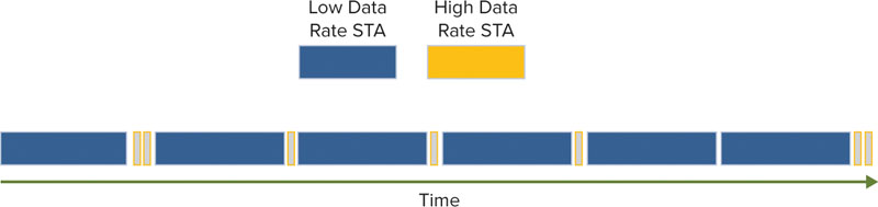
Figure 10.16 shows two stations contending for access to the wireless medium. One station is operating at a high data rate and the other is operating at a low data rate. In this scenario, both stations will statistically win contention a similar number of times. They may be transmitting the same amount of data during each transmission opportunity, but the amount of time it takes to transmit that data is highly divergent. The 802.11 arbitration protocols are designed to create relative equality in contention, but the use of airtime in this example is hardly “fair.” The station operating at a low data rate is taking up about 20 times more airtime than the station operating at a higher data rate, but they both transmit the same amount of data. In the real world, you may have an 802.11n AP that supports client stations operating at 300 Mbps, and you may have stations in the same service set operating at 1 Mbps. It’s simple math, but that’s a 300:1 difference in airtime for the same amount of data.
To eliminate this unfairness, vendors use proprietary scheduling and queuing mechanisms that seek to balance the airtime usage on a PHY-specific—or data rate–specific—basis, which improves aggregate performance for the entire network. In fact, airtime fairness improves performance for stations operating at high data rates, and the impact on stations operating at low data rates is very minimal. So, it is a win-win for the entire BSS. Figure 10.17 shows the same two stations from Figure 10.16, but this time they are using the airtime more efficiently.
FIGURE 10.17 Airtime fairness in action
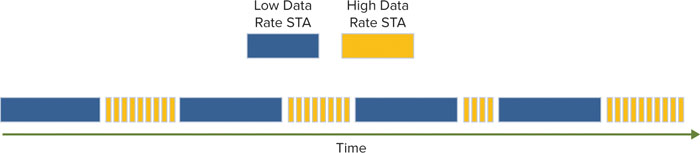
The basic logic behind airtime fairness is that stations connecting with higher data rates should be afforded more opportunities to transmit data because they are using the wireless medium much more efficiently than stations operating at low data rates.
For the most part, airtime fairness is a downstream technology performed by the AP. It is important that the AP be the decision maker because fairness scheduling algorithms can be applied to data more effectively with a holistic, BSS-wide perspective of data flow. This prevents latency-sensitive traffic from being under-prioritized in favor of high bandwidth data at higher rates, and it also prevents a few stations with low data rates from crippling the network’s performance.
Though airtime fairness is not yet a ubiquitous feature, many vendors have assimilated it into their products. If you are supporting lower data rates and have clients with highly divergent speeds within your WLAN, airtime fairness can be a helpful tool to avoid some problems. In a typical configuration, the administrator can specify a priority or a weight to be applied to user groups, SSIDs, or WLAN policies—specific configuration steps and procedures will vary by vendor. The complex scheduling algorithms do the rest.
As you can see from the long discussion about QoS, QoS is an important topic. Since the 802.11 protocol is primarily a MAC protocol, there are also several other topics to consider in the network deployment. Protection mechanisms are an important feature for networks with diverse client populations because there are many ways in which legacy clients can impede network performance. As we discussed in the “Airtime Fairness” section, one of the most harmful impacts of legacy clients is inefficient use of the airtime. Legacy clients also impact WLAN performance by requiring extra control overhead in the form of protection mechanisms when modern PHYs are used and backward compatibility is desired.
There’s no need to repeat the technical reasoning for protection mechanisms from CWNA, but we should discuss design practices related to their use. After many new PHY enhancements within the 802.11 standard, there is now a long line of backward compatibility. 802.11n is backward compatible with 802.11a/b/g and DSSS, 802.11g is backward compatible with 802.11 (DSSS) and 802.11b, and 802.11b is backward compatible with 802.11 (DSSS).
One of the big problems with backward compatibility, as prescribed by the standards, is that protection may be required when legacy devices are present, regardless of whether they are yours, your guests, or your neighbors. For that reason, protection mechanisms can be minimized but rarely avoided altogether.
At some point, network deployments must move past the model of backward compatibility in favor of higher-performance LANs. When standards bodies aren’t forcing this progress, it is up to network designers to influence this change. There are two ways to manage the use of protection mechanisms in a wireless environment:
- Configuration-related parameters that dictate how protection mechanisms are used and what mechanisms are supported
- The process of physically controlling the types of devices and PHY technologies in your network environment
Physical device control is a necessary, albeit limited, option because this type of control requires a lot of administrative work and authority. However, you can establish a baseline for device support on the network. For example, you may wish to remove all company-owned legacy (802.11b or earlier) APs and client devices.
In all up-to-date enterprise networks today administrators have the option to control the types of devices that access their network. This can be done by disabling or enabling certain data rate sets. If you’d like to prevent the oldest and slowest clients (802.11 DSSS) from joining your network, disable 1 and 2 Mbps data rates. To disallow 802.11b as well, disable 1, 2, 5.5, and 11 Mbps. Some vendors simplify this configuration step with an operability mode selection (e.g., 802.11g/n only; no 802.11b) for a BSS. Ideally, modern networks would eliminate all 802.11b and earlier devices, but this is not economically feasible or practical for many companies.
Further, some client devices rely on low data rates (like 1 and 2 Mbps) for essential functions. Some VoWiFi phones require these rates for broadcast frames, and some RFID tags also transmit “beacons” at these rates. So, even if you wanted to disable these rates to prevent other legacy clients, you could not.
On the client side, adapter capabilities and drivers vary in configurability; most client adapters have a limited set of user-defined protection parameters. In many adapters, nothing is user configurable. However, some adapters allow the user to configure the PHY mode, such as 802.11a/b/g, 802.11a only, and 802.11b only. The wireless PHY mode configuration option is shown in Figure 10.18 and may impact the AP’s protection response. In real-world networks, there’s no reason to support 802.11b but not 802.11g. However, this parameter can be helpful if you’d like to restrict a device to a certain frequency band. In addition to the operational mode, some adapters allow you to configure the type of protection used, such as request to send/clear to send (RTS/CTS) or CTS-to-Self. This option is shown in Figure 10.19 for a popular Intel adapter.
FIGURE 10.18 Setting the PHY operation on a client STA
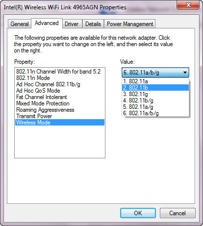
FIGURE 10.19 Configuring the protection mechanism on the client STA

802.11n introduces many new interoperability mechanisms and requirements as well. Many of these mechanisms are automated (not user configurable) and are simply a result of your chosen deployment model (such as 20 or 40 MHz channel widths) and supported features (like spatial multiplexing, Space-Time Block Coding [STBC], or short guard intervals [GI]). The primary design consideration here is to weigh the benefit of new 802.11n features against the drawback of protection mechanisms. Most 802.11n features are valuable enough to justify their use, but some may not be.
For example, as you entertain the idea of 40 MHz channels, you should consider how many 20 MHz-only devices (802.11a/b/g) will be present in the same frequency space. In the 5 GHz spectrum, you are more likely to get clean 11n 40 MHz operation with few protection requirements for 802.11a devices. However, in the 2.4 GHz spectrum, there are so many 802.11b/g devices in most environments that your 40 MHz channel will almost always be using some type of protection, thus nullifying any potential benefit from a 40 MHz channel. In fact, a 40 MHz channel may cause interference in the rest of your 2.4 GHz network and be more of a problem than a benefit. To that end, any 802.11n deployment or migration strategy should include a discussion of protection mechanisms, such as feature selection and configuration based on client PHY population, removal of legacy devices, and techniques to maximize the investment. With that in mind, network engineers should properly set expectations in accordance with the decision to support or not support legacy devices.
Power management is another one of those topics that becomes increasingly important with the proliferation of mobile Wi-Fi devices. As with protection mechanisms, many power management features are not user configurable and power save functionality is transparent to the end user. Because of that, the primary responsibility of network designers is to properly plan a deployment by ensuring that the infrastructure and client devices both support the intended power management features, the AP and client devices interoperate properly, the power management functionality doesn’t impact performance to unacceptable levels, and the desired amount of battery preservation is achieved.
There are two primary power management techniques:
802.11 Power Save (a.k.a. legacy power save) Legacy power save has been around for many years, and was a somewhat fundamental approach to conserving battery life. Client devices that support legacy power save functionality alternate between awake and dozing states and wake up to check in with the AP at regular, predefined intervals (DTIM Beacons) to see if the AP has frames buffered for it. If it does, the client requests delivery of those frames by transmitting a PS-Poll frame to the AP. This process continues until the buffer is empty.
WMM Power Save WMM Power Save (WMM-PS), which is the power save extension of the Wi-Fi Alliance’s WMM specification, is a more effective and important power save technique today. It works essentially the same way as legacy power save stations, but it is more flexible and efficient for a few reasons:
- First, WMM-PS stations can request frames from the AP at any time by sending trigger frames (if the AC is trigger enabled), which allows for more efficient and timely delivery of buffered frames.
- Second, WMM-PS is derived from WMM, so it provides a way for the client to request data for specific ACs instead of requesting any and all data destined for the client.
- Third, WMM-PS has different modes of traffic delivery, including scheduled and unscheduled; these delivery policies can be negotiated separately for each AC.
- Fourth, when the client station requests buffered data, the AP can empty the buffer in a burst; legacy PS required a separate poll frame from the client for each buffered frame.
As a Wi-Fi Alliance–certified feature, WMM-PS support can be identified for both client and AP devices by looking at the Wi-Fi Certified certificates found on the Wi-Fi Alliance’s website. The core functionality of WMM-PS is called Automatic Power Save Delivery (APSD), so you will often find that WLAN vendors use this term in configuration menus instead of WMM-PS. U-APSD refers to the unscheduled mode of APSD, which is the most common implementation. Most WLAN infrastructure configuration for WMM-PS is limited to enabling or disabling support for it on an SSID profile.
Power save features are directly correlated with performance. Dedicated devices like voice phones don’t use power save during an active call, but will enter power save mode whenever there is not a call, so this is not a big deal for voice performance during a call. For multifunction devices, like laptops or PDAs, power save functionality occurs during normal traffic flows, so it may add delay and jitter while reducing throughput, especially for downlink traffic. This is because the AP buffers the traffic until the client requests it, or until the scheduled delivery period. For uplink traffic, the client station can control awake and dozing states in cooperation with the flow of its data from the application layer. When your client devices support high-performance features like frame aggregation, channel bonding, spatial multiplexing, and Multiple Ratio Combining (MRC), you will notice that battery life will be shorter. Usually, there’s not much you can do about this from the client side unless the client driver or provisioning utility allows you to enable or disable specific features. Most devices today are not quite this granular.
However, there are client-side configurations that can improve battery life. In addition to standardized power save features, transmit power has a direct relationship to battery life. If mobile devices are transmitting at maximum power, more battery life will be used; if you find that devices are quickly running out of juice, consider modifying the transmit power settings. TPC may also help to control optimal client transmit power so that clients aren’t unnecessarily using battery life with excessively high transmit power. As you weigh the output power of client devices, remember to seek a balanced power ratio between the client and AP. So, you won’t want to configure the client for low transmit power if this has a negative impact on the link balance.
As you research client device capabilities, you will find that manufacturers of battery-sensitive devices make most of the battery conservation decisions as a part of engineering, and they remove these decisions from the customer. Case in point, VoWiFi phone manufacturers are highly conscious of battery life. For that reason, as of this writing, only one dedicated VoWiFi phone manufacturer has made an 802.11n phone because 802.11n is usually a higher-performance protocol that requires more battery life. Many manufacturers also restrict their voice devices to 2.4 GHz to conserve power—because 5 GHz requires larger antenna elements or more power to collect the same amount of signal as in 2.4 GHz. Similarly, manufacturers of mobile devices (mobile phones, tablet computers, netbooks, etc.) that support Wi-Fi are also limiting the capabilities of their devices. For those that do support 802.11n, they’re usually 1x1 or 1x2 MIMO only.
Power save can also have BSS-wide performance implications for broadcast and multicast traffic. Specifically, when a power save device is dozing, the AP buffers unicast traffic to that station. It also buffers all group addressed traffic to the BSS because at least one member of the BSS is incapable of receiving it. At each DTIM interval, the dozing station(s) wakes up to receive frames buffered for it, and also for the delivery of group addressed frames to the BSS. The problem with this is that some latency-sensitive applications natively use multicast traffic for delivery. Multicast video streaming and multicast voice sessions are example applications that would be impacted by power save functionality.
In most cases, even if the DTIM interval is set to 1 (every Beacon is a DTIM Beacon), latency-sensitive multicast applications still won’t function properly. Some vendors have sought to remedy this by translating multicast traffic for some applications into unicast data streams, but not all vendors have such a solution. This means that either power save functionality must be disabled, power save devices must have their own SSID (without sensitive multicast applications), or latency-sensitive multicast applications simply won’t work.
802.11n also introduces new power save modes called Power Save Multi-Poll (PSMP) and Spatial Multiplexing Power Save (SMPS). For the purposes of network design, these power save modes have not yet become significant as selection criteria or device configuration options. 802.11n chipsets have not reached full maturity, so spec sheets tend to be slim on 802.11n power save details. Even if devices do support SMPS and PSMP, there are not likely to be any configuration parameters for client devices.
The details of these operational modes are covered in the CWNA Certified Wireless Network Administrator Official Study Guide: Exam PW0-104, First Edition, by David D. Coleman and David A. Westcott (Sybex, 2009).
Mission-critical applications, real-time applications, and latency-sensitive applications have specific and demanding network service-level requirements. So that users of these applications have acceptable performance, you need to ensure the following:
- Application performance levels are maintained as clients move throughout an ESS.
- Roaming occurs with low latency and is fully transparent to end users.
- Security, data reliability, and low retransmission rates are maintained for mission-critical applications.
This combination of requirements demands that network designers focus on roaming and mobility in a secure network.
As we will discuss in Chapter 12 (“Advanced Enterprise WLAN Security Design”), 802.1X/EAP authentication can take more than a full second to complete. During a client reassociation, this amount of delay will cause a noticeable service outage for most latency-sensitive applications. For some real-time applications, this much delay can cause a timeout to the application’s session, forcing users to manually reconnect a phone call or initiate a new client/server session. This is a considerable problem for application performance, as illustrated in Figure 10.20.
FIGURE 10.20 The 802.1X/EAP slow roam process
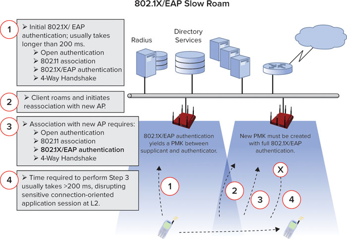
There are several technical ways to address this problem when 802.1X/EAP is required, but most of them have limitations. In this next section, we will look briefly at the technical approach to each fast secure roaming—often abbreviated as FSR, mechanism and discuss their strengths and weaknesses. We will then discuss roaming optimization and finally cover other roaming considerations.
Layer 2 Roaming Methods
As a MAC protocol, the 802.11 standards bodies have provided several options for fast secure roaming at Layer 2. In addition, proprietary solutions have been introduced to improve on the MAC framework offered by the 802.11 protocol.
PMK Caching
PMK caching (a.k.a. fast roam-back) is defined in 802.11-2007. How does PMK caching work? In short, an 802.1X/EAP authentication yields a pairwise master key (PMK), which is used as an input for dynamic encryption key generation at the supplicant and authenticator. Instead of discarding the PMK after the association is destroyed (e.g., disassociation, reassociation, or deauthentication), the PMK is cached on both devices and a PMK identifier (PMKID) is calculated as a reference to that specific PMK. So, when the client roams back to that AP, it looks for a valid PMK for the AP, and if it finds one, it references the PMKID in the reassociation frame. The PMK is reused instead of re-creating one with a full 802.1X/EAP authentication.
While helpful, PMK caching is limited in that it only helps a client “roam back” to an AP to which it has previously performed a full 802.1X/EAP authentication. This means that every time the client roams to a new AP, it will be a slow roam—full 802.1X/EAP authentication. This has limited effectiveness and benefit. PMK caching is shown in Figure 10.21.
FIGURE 10.21 How PMK caching works

Preauthentication
The other 802.11-standardized method, preauthentication, takes a different approach. To address the obvious flaw with PMK caching, preauthentication seeks to preestablish a PMK between the client and all APs to which the client may roam in the future. Before roaming, the client initiates an 802.1X/EAP authentication with other APs through its current AP via the wired network. PMKs are created and then stored on both the client and potential future AP with a PMKID to reference that PMK. When the client roams to a new AP, it references the previously created PMKID in the reassociation request frame, thus allowing a fast roam.
While helpful, the problem with preauthentication is that the implementation is limited for various reasons:
- It causes extra traffic on the network
- It puts extra and unnecessary load on the authentication server and user databases.
- It is essentially a “cover all the bases” approach that is highly inefficient.
For preauthentication to be successful, clients must accurately know and predict the APs to which they may roam or they must roam with every AP in the vicinity. Preauthentication is shown in Figure 10.22.
FIGURE 10.22 The preauthentication process
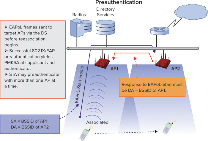
Opportunistic Key Caching
One of the best solutions to-date is opportunistic key caching (OKC). In its simplest form, OKC is a hybrid between PMK caching and Cisco’s proprietary method, Cisco Centralized Key Management (CCKM). OKC takes PMK caching a step further and “opportunistically” shares cached PMKs with other APs within a mobility domain or RF neighborhood. Thus, when a client roams, a PMK is already present on the target AP and the client only needs to reference the PMKID in the reassociation request frame. The PMKID value comes from a formula that includes the client MAC address as well as the BSSID, which allows for unique per-AP and per-client combinations. Seems simple, right?
Unfortunately, OKC suffers the ill fate of nonstandardization. Symbol and Microsoft were co-creators of OKC, but it is not well documented or standardized anywhere. For that reason, not all implementations of OKC are compatible or consistent. By now, most infrastructure vendors are supporting OKC except those with a vested interest in a proprietary solution. But many client vendors have been slow to adopt OKC, so client support is sporadic. OKC is shown in Figure 10.23.
FIGURE 10.23 The opportunistic key caching (OKC) process

Of these three previously mentioned roaming mechanisms, a consistent problem is client support. Most enterprise networks support many different client types, but client vendors have been highly inconsistent in their support of fast roaming methods. Additionally, even when a client supposedly supports one of these mechanisms, the implementations are often quite poor. For example, with OKC, clients may only send a PMKID in the reassociation request half of the time. This causes a number of problems and does not lead to administrator confidence or user satisfaction.
802.11r Fast BSS Transition
The most promising solution for fast secure roaming is 802.11r Fast BSS Transition (FT), which is defined by 802.11r. The technology that comprises FT is far more complex than the previously discussed roaming methods. The intricate details of its operation are not pertinent to the purposes of this book, so we will spare the details for this discussion. At present, FT is not supported by any AP or client vendors, and its support will largely be postponed until the release of the Voice Enterprise certification by the Wi-Fi Alliance. The Voice Enterprise certification has been in progress for multiple years now and is finally reaching maturity. It is reaching the final stages of the Wi-Fi Alliance’s testing and support process and should be released sometime in the middle of 2011. In addition to 802.11r, Voice Enterprise is based on functions introduced by 802.11k and 802.11v.
In short, FT works in a similar way as OKC, but it is more efficient. FT seeks to modify the frame contents of the reassociation request/response exchange as well as the 4-way handshake to make them more efficient. FT introduces new keying concepts, key holders and distributors, and other ancillary information about mobility domains and groups that is relevant to mobility transitions.
You should know that FT is a promising set of protocols that will drastically improve on client roaming methods. FT is standardized (by IEEE) but is not yet a certified roaming platform (by Wi-Fi Alliance); however, it is an efficient, resourceful, and effective method that looks to be a de facto solution for years to come. For now, we must simply await its acceptance and proliferation, which will not happen overnight.
For more information and a deep technical dive on Fast BSS Transitions as well as any of the other roaming mechanisms discussed in this section, see the Robust Security Networks (RSN) Fast BSS Transition (FT) whitepaper authored by Devin Akin. This whitepaper is offered free of charge by CWNP and can be obtained at http://www.cwnp.com/pdf/802.11_RSN_FT.pdf.
Proprietary Solutions
In addition to the previously mentioned fast secure roaming methods, we have proprietary mechanisms from Meru and Cisco. Other vendors also offer proprietary enhancements to the previously mentioned protocols, but no other vendors have comprehensive solutions like the two offered by Meru and Cisco.
Single-Channel Architecture Meru pioneered the single-channel architecture (SCA), which uses a single BSSID (per-SSID or per-client) across all APs on a given channel. Client devices interpret the single BSSID as a single large AP, and the WLAN infrastructure takes care of transparently optimizing the client’s association by quickly transferring the client’s association to different APs. It is probably safe to say that this method is the most efficient and effective form of roaming available today, but it is proprietary and limited to a single vendor. Also, this solution requires support for the much contested single-channel architecture. We discuss the SCA approach to roaming in greater detail in Chapter 5, “Vendor and WLAN Architecture Selection.”
Cisco Centralized Key Management (CCKM) We also have CCKM, which has received pretty good market penetration due to Cisco’s market share leadership. With CCKM, a WLAN controller or AP provides WDS (Wireless Domain Services) functionality within an ESS. WDS functions consist of caching and forwarding PMKs to other APs within the ESS. CCKM is basically a Cisco-specific version of OKC. CCKM requires client support and participation (CCKM compatibility) as a part of the Cisco Client Extensions (CCX) program. This limits the supplicant selection and may add cost to the supplicant deployment. As with Meru’s proprietary option, CCKM locks a customer in with a single vendor.
Overview of the Roaming Landscape
Among these options, no single approach will work for all occasions. Although they each have drawbacks, the network designer should evaluate which of the drawbacks are tolerable for the deployment scenario. Both of the proprietary solutions have strengths, but so does OKC. Client support will be a major part of the final decision. When the Wi-Fi Alliance releases the Voice Enterprise certification and vendor adoption is pervasive, Voice Enterprise will be our best choice in most cases. As of this writing, it is difficult to know how far in our future this will be.
If these options do not meet your business or application needs, other security solutions, such as WPA2-Personal, or per-user preshared keys (PPSK) are recommended. We will discuss this further in Chapters 11 (“Basic WLAN Security Design”) and 12 (“Advanced Enterprise WLAN Security Design”).
Roaming Optimization
In all roaming methods except Meru’s proprietary technology, client devices are the decision maker when it comes to roaming. The roaming algorithms of client drivers dictate when and where a client will attempt to reassociate with a new AP. In general, client roaming algorithms initiate a roam when signal quality (as determined by RSSI, SNR, data rate, collisions/retries, and/or dropped frames) changes below a certain threshold. For this reason, RF design techniques should account for the types of client devices—and resultant roaming behaviors—that will be present within the network.
Proper site surveying should indicate typical roaming boundaries for client devices, and designers should attempt to plan these boundaries strategically. Of course, you can’t be expected to control every roaming boundary all the time, but you can reduce pain points by monitoring roaming boundaries in popular user congregation or transitional areas.
A common example for user congregation is nurse stations within a hospital. Nurses commonly gather in these areas with voice phones in tow, and you do not want the phones to be encountering a roaming boundary right in this area. That may cause the phones to perpetually roam back and forth while nurses remain in the same location. By the same token, if you can’t eliminate “slow roams” from your network, try to plan the slow roam boundaries at natural transition areas, such as between buildings on a campus.
You will also want to consider the role of WLAN controllers in the roaming process. We will talk more about intercontroller roaming in the next section, “Other Roaming Considerations,” but the key point here is that you want to avoid intercontroller roaming where possible. In other words, if half of your APs are homed to one controller and the other half are homed to another controller, you do not want to stagger these APs in the deployment so the clients are walking down the hall and continuously roaming back and forth between APs on different controllers. This has been referred to as a salt and pepper approach (which has the appearance of RF coverage resiliency if a controller fails), and it is not optimal.
There are many other fine points of consideration for optimizing roaming, but one final suggestion is to carefully set your 802.1X key timeout intervals (or rekeying interval). This value will determine when the client will be required to create a new key by means of a full 802.1X/EAP authentication. Some companies with aggressive security policies set this value to 15 minutes, but this is not usually advisable. This value should be set to coincide with times that the client device is not likely to be in use, such as at break times or shift changes. This will prevent an application session from being terminated as a result of forced rekeying.
Other Roaming Considerations
In addition to the mobility topics discussed thus far, there are several other issues to think about, such as the difference between inter- and intracontroller roaming, Layer 2 and Layer 3 roaming, and the distinction between mobility groups. We will discuss these topics next.
Centralized Architecture Roaming
There are two general types of roaming in a centralized architecture:
Intracontroller Roaming In intracontroller roaming, clients are roaming between APs managed by the same controller. Intracontroller roaming is a simple process because WLAN controllers are typically managing client security keys, QoS and security policies, and more, and can easily move them from one AP to another within the controller itself.
Intercontroller Roaming In intercontroller roaming, clients are roaming between APs on different controllers. Controllers must transfer client state information, keys, buffered frames, and policies, which requires more time, coordination, and traffic overhead. When possible, limit the amount of intercontroller roaming. Controller-to-controller handoffs rely on proprietary communication that is usually transparent to the network administrator, but for those vendors that provide configuration parameters for controller-to-controller communication, it is important that settings be optimized for roaming. Generally, it is required that controllers be assigned to the same mobility group for intercontroller roaming to occur seamlessly.
L3 Roaming
In our roaming discussion thus far, we’ve been primarily concerned with moving a client association at Layer 2. However, Layer 3 roaming also occurs and requires additional techniques. Different WLAN controllers/APs within the enterprise are often on different VLANs. When a client roams from a controller/AP on one VLAN to a controller/AP on another VLAN, this would normally require that the client obtain a new IP address for the new subnet. This is known as Layer 3 (L3) roaming. If the client must obtain a new IP address, this means that all sessions above the IP layer will be terminated, which is bad.
Most vendors handle the problem of L3 roaming by forming an IP tunnel between the new controller/AP and the old controller/AP. The client traffic is thus sent to the new controller/AP, encapsulated in the tunnel, and forwarded to the old controller/AP for processing. In this way, the client’s association is transparently maintained at the old controller/AP and on the old subnet. This allows the client to maintain its IP address on the old subnet, thus preserving application sessions. This concept is often referred to as anchoring, and you will find this term in the configuration menus of some vendors.
Tunneling is generally a good thing because it maintains the flow of application data. However, one problem with L3 tunneling is that it adds latency and additional network hops to network traffic. Depending on the type of application in use, it may be desirable to force the client to obtain a new IP address on the new subnet so as to avoid the extra latency incurred from tunneling. In an ideal world, this would be delayed to a time after the application session has ended. In most cases, the WLAN infrastructure will force the client to obtain a new IP address after a certain interval.
Mobility Groups and Domains
The terms mobility group and mobility domain vary from one vendor to the next. Commonly, the term mobility group refers to a set of WLAN controllers or APs within which mobility messages are shared and roaming is expected to be commonplace. Mobility domains, on the other hand, are sets of mobility groups within which roaming is supported but is not expected to happen as frequently. The implementation of mobility groups and domains is dependent on the vendor, and designers should understand how mobility is, or is not, supported or required between groups and domains.
In addition to the larger topics we’ve already addressed in this chapter, you need to take into account more subtle MAC configuration parameters when deploying a WLAN. These parameters will vary from one vendor to the next, but there are many consistencies. They usually fit within the realm of a “WLAN profile,” which may be called a WLAN or a virtual AP. We will discuss the most common of these parameters in the following sections.
SSID
We’ve already discussed some of the basic SSID configuration suggestions in other areas of this book, but we’d like to include a brief discussion of SSID conventions here as well. At the most basic level, an SSID should be configured in accordance with the policies and intentions of the company. When multiple SSIDs are supported by each AP, SSID naming conventions should facilitate end users in their discovery and selection of a network. Network designers will want to minimize help-desk calls by making network selection clear and easy.
We discuss the topic of SSID hiding in Chapter 11, so we will not go into great detail here. There may be administrative reasons to hide the SSID, but it is not recommended as an effective security tactic. The same logic applies to AP configurations that allow the AP to ignore broadcast probe responses.
The most important aspect of SSID design is deciding how many SSIDs to support on each AP. The answer to this question will largely depend on the types of services supported on the WLAN as well as the expected traffic load. Many network administrators go about the SSID creation process somewhat haphazardly, adding new SSIDs as they see a need for a new service. However, too many SSIDs can quickly cause an excess amount of management overhead on the wireless channel.
Every SSID must transmit a Beacon stream to broadcast its presence, and Beacons are usually transmitted every 100 ms by default. Consider for a moment that you have enabled eight SSIDs on each AP and you have four visible APs in a given area on a specific channel—32 Beacon streams. Then remember that broadcast traffic is transmitted using a basic data rate. So, you have 32 Beacons every 100 ms transmitted at a low data rate. Given the size of 802.11n beacons, that is a lot of airtime being used up for beaconing. In some network environments with many SSIDs and densely deployed APs, management traffic alone can account for 30–50 percent (or more) of a channel’s capacity. This is often referred to as management frame poisoning because this much management traffic will severely impact application performance when any amount of load is placed on the network.
If you notice that your beacon traffic is reaching unacceptable levels, one simple remedy would be to combine like services onto a single SSID. Then take advantage of user-based or group access control assignments to differentiate the allowed services within a single SSID. This can be done with RADIUS return attributes or by other authentication methods supported by most vendors.
There are other considerations as well. Most WLAN vendors employing the centralized architecture (WLAN controller and APs) are creating L3 tunnels between the AP and WLAN controller. However, in a few vendor implementations, we’re not talking about a single L3 tunnel for an AP to a controller. We’re talking about a single L3 tunnel for each SSID on each radio for each AP. In other words, if you have a dual-band AP with four SSIDs in each band, there would be eight separate L3 tunnels between the AP and the WLAN controller. Many WLAN designers can be myopically focused on the wireless side of the network without considering the implications this will have on the wired side. While these tunnels may not create an extraordinary amount of traffic on the Ethernet switches, they do put a lot of stress and strain on the CPU of the WLAN controller. If you have a WLAN controller that supports 250 APs and you load it down with eight SSIDs per AP, you may quickly realize that WLAN performance suffers as a result of excess tunneling.
Each vendor does tunneling a bit differently, so you should find out how your vendor tunnels traffic between the AP and WLAN controller. This topic has not been widely publicized and is unknown to many administrators, but it has severe implications for WLAN design. As a best practice, when possible, limit the number of SSIDs on each AP to four or less. Monitor the amount of management traffic required to sustain your SSIDs, and this will help you identify if it is becoming problematic to your applications.
Beaconing
As we think about SSIDs and management traffic, the Beacon interval becomes an important parameter. Every vendor has standardized on a default Beacon interval value of 100 ms (actually, it is 100 Kμsecs, which is often rounded to 100 ms for simplicity), but this is usually a configurable parameter. If you must support a high number of SSIDs, you can modify the Beacon interval to a higher value (such as 200 ms), but this approach is generally not recommended. Some client device drivers begin to display aberrant behaviors when they do not see a Beacon every 100 ms. Similarly, some client devices are configured to passively scan a channel for 110 ms before moving on to another channel. This allows them to catch a Beacon, interpret the information, and move on to the next channel. If the Beacon interval is higher than the default 100 ms, you may have client connectivity issues (creating or maintaining a connection).
The DTIM interval is a value that determines what Beacon frames are DTIM Beacon frames. In power save operation, dozing stations must awake for every DTIM Beacon. After a DTIM, all buffered multicast and broadcast traffic is delivered to the BSS; following that, power save stations can request their buffered frames from the AP. In general, a DTIM between 1 and 5 is normal, but traffic requirements will dictate this need. Some WLAN client vendors suggest configuring every Beacon as a DTIM (value of 1) to minimize delay in the delivery of multicast and broadcast traffic. This is especially true of mildly latency-sensitive applications that rely on either multicast or broadcast traffic for some function. The DTIM interval configuration parameter is shown at the top of Figure 10.24.
FIGURE 10.24 DTIM, data rates, and other configuration parameters
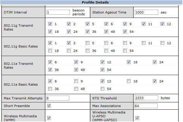
Supported and Basic Data Rates
Another important step in deploying a WLAN profile is to enable or disable data rates for the BSS. The primary purpose of this step is to maximize the efficiency or availability of the WLAN channel. As legacy clients join a service set or associated clients move to the edge of the service area, their data rate will naturally drop as a function of dynamic rate switching. These slower devices will then have an adverse impact on channel utilization. So, the enabling or disabling of specific rates is largely a balance between availability and broad client support on the one hand and performance and efficiency on the other hand.
If you intend to support legacy devices (802.11 DSSS or 802.11b), you will have to leave some legacy rates (1, 2, 5.5, or 11 Mbps) enabled. However, when you allow clients to connect at low data rates, you leave the door open for a single client to severely impact channel utilization by taking a long time to transmit a small amount of data; this impacts everyone.
In most multiservice WLANs, it is advisable to disable support for at least the lowest data rates (1 and 2 Mbps) in favor of higher rates. Some engineers may prefer to be more aggressive in their data rate support by also disabling 5.5 Mbps within the BSS. If you are providing backward compatibility for 802.11b, 11 Mbps could still be supported. Or, if you prefer to disallow DSSS and 802.11b devices, you can simply disable all of these legacy rates. These configuration parameters are shown in Figure 10.24.
The Basic Rate Set for a BSS is a set of data rates that must be supported by all stations in the BSS. So, if you desire to support 802.11b, you will want your Basic Rate Set to reflect 802.11b capabilities (e.g., make 5.5. and 11 Mbps a basic rate but not 6, 12, 24, etc.). When selecting a basic rate, the important thing to know here is all devices must support these rates, and frames with multicast or broadcast addresses, as well as some control frames, are always sent using a basic rate. So, if 1 and 2 Mbps are your basic rates, you will see a lot of traffic at these low rates. This will adversely impact utilization of the wireless medium.
However, as you will find as you begin testing your data rate configurations, client drivers are sometimes unpredictable. For no apparent reason, some client devices will not function properly if certain data rates are not supported. Thus, you should monitor your data rate selection carefully and keep these parameters in mind if you find connectivity problems after changing the supported or basic rate set. Of course, disabling lower data rates is an effective way to ensure that your WLAN channel is being used efficiently, and this tactic is becoming increasingly common, especially in environments with high user densities and latency-sensitive applications. Many VoWiFi design guides encourage engineers to disable lower data rates.
Band Steering
In the wake of dual-band 802.11n APs and the continued desire to maximize wireless capacity, WLAN infrastructure vendors have sought proprietary ways to make maximum use of the unlicensed frequency spectrum. By now, readers of this book should be familiar with the differences between the 2.4 GHz and 5 GHz frequencies, including the number of channels and common uses for these bands. 2.4 GHz has only three nonoverlapping 20 MHz channels and is typically pretty saturated with Wi-Fi and non-Wi-Fi interference sources. The 5 GHz bands offer up to 24 nonoverlapping 20 MHz channels (depending on regulatory domain)—or fewer bonded 40 MHz channels—and are typically much “cleaner” RF bands. In other words, far fewer devices are currently using the 5 GHz bands, which makes their use for Wi-Fi far more desirable.
To take advantage of the highly available 5 GHz bands, some vendors have introduced a proprietary feature called band steering. The simple goal with band steering is to attempt to move 5 GHz-capable client devices into 5 GHz bands and out of the 2.4 GHz band. Each vendor’s version of band steering works a bit differently, but the basic functionality is generally the same.
Almost every Wi-Fi device that is 5 GHz capable is also 2.4 GHz capable. Unfortunately, client software drivers are not consistently implemented to prefer the 5 GHz band and to use the congested 2.4 GHz band as a last option. So, the WLAN infrastructure must attempt to simulate this priority by selectively responding to, or avoiding response to, the client’s active scanning attempts. The intention is to make the client think that a service set is only present in the 5 GHz spectrum, which would cause them to initiate authentication in 5 GHz instead of 2.4 GHz.
Because of its efficiency for scanning a large number of channels, most client devices prefer active scanning over passive scanning. This is a good thing for band steering, because clients could always use Beacon streams to identify a BSS. Unfortunately, the biggest problem with band steering is that client drivers are all different. Some devices that are 5 GHz capable are still very reluctant to associate in the 5 GHz band, so they will continue scanning the 2.4 GHz band despite the presence of 5 GHz networks. In most implementations of band steering, the AP will ignore the clients’ first several (usually two or three) probe requests in the 2.4 GHz band, and if the client does not join in the 5 GHz band, the AP will eventually begin responding to the client’s probes in the 2.4 GHz band as well. This concept of band steering is shown in Figure 10.25.
FIGURE 10.25 Typical implementation of band steering

As you have probably gathered, band steering isn’t effective for every client, or in every circumstance. However, it does work for many client devices and is a highly valuable feature, especially for high-density deployments. If you have ever sought an automated way to maximize the 5 GHz bands while providing the same service sets to 2.4 GHz and 5 GHz devices, band steering is the answer.
While band steering is largely an automated process that is configurable within the WLAN infrastructure, the same net effect can often be achieved with some careful network planning and provisioning. The simple principle here is to configure similar service sets for 2.4 GHz and 5 GHz bands, but to use different naming conventions for the SSID.
For example, the SSID for the 5 GHz service set may be “FastWiFiAccess,” and the SSID for the 2.4 GHz service set may be “SlowWiFiAccess.” When end users scan for available networks, they see these two options—fast and slow Wi-Fi—and end users will likely choose the fast option. If the client device is not 5 GHz capable, a network scan will only discover the 2.4 GHz network, and the user will have no choice but to join the “slow” network. This type of SSID naming is a manual way to offload network traffic from 2.4 GHz and put it on 5 GHz. This is sometimes jokingly called poor man’s band steering.
Both manual and automated band steering methods can be effective ways to optimize the client load across the spectrum. Simple configuration options like this can go a long way toward alleviating congestion from high user densities in the crowded 2.4 GHz band.
Frame Aggregation and Fragmentation
802.11n introduced a new efficiency mechanism called frame aggregation, which enables a transmitter to combine multiple MSDUs or MPDUs into a single frame for transmission. You may remember that in years past, the opposite trend, called frame fragmentation, was more popular.
In most of today’s networks, aggregation is more useful than fragmentation. The purpose behind fragmentation was to split large frames into multiple smaller frames so as to minimize collisions on heavily utilized WLAN channels. The problem with fragmentation is that it was not beneficial in many environments and it added management overhead. However, it was useful in some environments, largely because legacy RF handling mechanisms (like simple diversity) were not robust enough and data rates were not efficient enough to combat environments with high multipath and dense user populations.
Frame aggregation is made possible by 11n’s superior signal transmission and reception technologies as well as the higher data rates that are supported. Higher data rates allow more data to be transmitted in a shorter amount of time. By aggregating multiple MSDUs (A-MSDU) or MPDUs (A-MPDU) into a single frame transmission, you improve channel efficiency by reducing management overhead. However, aggregating data frames is not always beneficial to a service set.
First, frame aggregation is great for cramming a lot of data on the wireless medium. However, throughput is not always the most important metric for application performance. When throughput takes priority and individual frame transmissions take a longer amount of time to complete, less airtime is available for other devices, like voice phones, that must access the medium frequently and consistently to transmit small amounts of data. In networks with a high number of voice clients, frame aggregation can be harmful to voice flows.
Both A-MSDU and A-MPDU can be supported at the same time. Aggregation configuration is usually made at the radio level of a WLAN, but it is a MAC-layer feature. In configuration menus, you will often find configuration options to enable or disable each type of aggregation as well as a maximum A-MSDU or A-MPDU size. In almost every case, you will want to keep the default size configuration. One vendor’s configuration parameters for frame aggregation are shown in Figure 10.26.
FIGURE 10.26 Frame aggregation parameters for Motorola

Additional Configurations
In addition to the previous list of common WLAN profile configuration parameters, every vendor has their own list of additional configurations. These include options like the following:
Client Timeout (or Ageout) Values The length of time a client can be idle before its association is destroyed.
RTS Thresholds The maximum value of an RTS control frame.
Client Limits The number of clients that can be supported on a specific SSID or AP at a time.
Proprietary Optimization Features These are various as there are many different proprietary features that may enabled on a WLAN. Consult vendor documentation for details.
Peer-to-Peer (P2P) Blocking Prevents clients within a BSS from communicating directly with one another through the AP.
Protected Management Frames These enable protection for some management frames so that attackers cannot conduct certain types of attack.
Fragmentation Thresholds If fragmentation is in use, frames larger than the fragmentation threshold are divided into multiple separate frames. In many legacy networks with high utilization, frame fragmentation was helpful for minimizing collisions and maximizing channel efficiency.
IDS Behaviors There are many IDS behaviors that may be tied to a WLAN, such as channel scanning behaviors, client or rogue priorities, and many more.
These are just a few. A sample set of these advanced configuration parameters is shown for two different vendors in Figure 10.27 and Figure 10.28. Because we can’t address each configuration option exhaustively, our best approach is to defer to vendor documentation. Often, feature naming conventions vary from vendor to vendor, so it is always helpful to consult the documentation. Similarly, many of these features are offered by most vendors, but the exact implementation or configuration parameters vary.
FIGURE 10.27 Advanced configuration parameters

FIGURE 10.28 More advanced configuration parameters
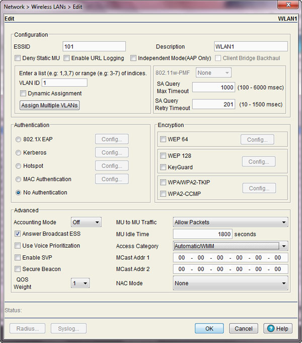
In this chapter, we looked at many of the features and technologies that take a WLAN from a base set of functionality to high-performance, mission-critical, multiservice functionality. There are many aspects to a high-performance WLAN deployment, but since the 802.11 protocol is primarily a MAC-layer protocol, it should come as no surprise that MAC-layer considerations are absolutely essential. More and more enterprise companies are turning to the WLAN to meet the connectivity needs of increasingly mobile clients, and MAC-layer features accommodate this demand.
With this new emphasis on WLAN usage, the shared contention domain of unlicensed frequencies is becoming increasingly crowded. Unfortunately, bandwidth resources on Wi-Fi networks are limited, and as more devices contend for this resource, it is important to allocate these resources properly. That is the role of QoS. While QoS doesn’t add any more bandwidth, it does provide more discriminating use of the available bandwidth. With such a diverse set of applications on the WLAN, end-to-end QoS is absolutely essential for creating priority for some applications. Wireless QoS is a unique challenge by itself. But in addition to wireless considerations, the wired network must be provisioned properly. Then the WLAN must integrate properly with the wired network. It’s a large hurdle but a necessary one. Without QoS, many mission-critical applications won’t live up to their intended uses.
Many of the same mission-critical applications that require QoS are also power sensitive. Mobile devices are a new breed of network-connected electronics, and there is always a balance between performance and power conservation. In this chapter, we looked at important design considerations for protecting battery life while maintaining optimum performance levels. Power-saving protocols, like WMM Power Save, are an important piece to this puzzle.
Roaming is also an important part of mobility in the enterprise. With so many options for roaming protocols, it is important for us to understand the options as well as the strengths and limitations that come along with each protocol. There are many detailed design considerations to facilitate effective roaming.
In addition, you must take into account many other MAC-layer configuration options and deployment considerations. As devices with different PHY capabilities populate the airwaves, MAC-layer protocols are left to help everyone play nicely together. Protection mechanisms serve this purpose, and their use has many implications.
No MAC design discussion is complete without talking about the many checkboxes and custom fields that are a part of any WLAN infrastructure and client solution. There are so many common vendor-specific MAC features that we couldn’t possibly address them all. To that end, we will defer to user guides and vendor-specific implementations.
Identify the need for QoS and explain its significance. Recognize why QoS is necessary and understand how application requirements and limited network resources demand it. Also understand how it benefits application performance.
Demonstrate a thorough knowledge of WLAN arbitration. Understand the relationship between WLAN arbitration and application performance, particularly as it relates to QoS.
Illustrate a comprehensive understanding of QoS technologies. Illustrate the technical intricacies of wired and wireless QoS as well as integration of WLANs with the wired network.
Explain the benefit and operation of proprietary optimization features. Understand the purpose, functionality, and benefit of proprietary optimization features like airtime fairness, band steering, and others.
Illustrate best practices for roaming support in a WLAN. Understand the technologies and protocols related to roaming in a WLAN. Explain different types of roaming, challenges related to roaming, vendor-specific processes to handle roaming, best practice for client roaming, and the limitations and benefits of specific roaming methods.
Explain best practices for deployment of power management features and PHY protection mechanisms. Understand the technologies related to power management in WLANs and illustrate when and how they should be implemented. Understand how different PHY technologies interoperate and how to properly plan for their presence in a network environment with protection mechanisms.
Explain best practices for common WLAN feature support, configuration, and deployment strategies. Demonstrate a thorough understanding of common WLAN configuration parameters and identify when and how to configure them.
1. What parameters are included in the EDCA parameter set? (Choose all that apply.)
A. CWmin
B. CWmax
C. AIFSN
D. Slot time
2. A MAC frame is marked with a UP value of 6. To which WMM access category (AC) would this frame be mapped?
A. AC_VO
B. AC_VI
C. AC_BE
D. AC_BK
3. What new power management mechanisms were introduced with 802.11n? (Choose all that apply.)
A. PSMP
B. WMM PS
C. SMPS
D. MRC PS
E. MIMO PS
4. According to industry best practices, what is the recommended maximum number of SSIDs that should be supported on each AP radio?
A. 1
B. 2
C. 4
D. 8
E. 16
5. How does band steering typically work?
A. Band steering is a client-side feature that allows the client device to measure channel utilization and select an AP and operating channel based on frequency congestion.
B. Band steering forces clients to join in the 5 GHz band by stopping an AP’s Beacon stream when the client load threshold is reached.
C. Band steering is a load-balancing mechanism used by WLAN controllers to move a client association from the 2.4 GHz band to the 5 GHz band using channel switch announcement messages.
D. Band steering attempts to move 5 GHz–capable stations to the 5 GHz band by withholding probe responses when the client sends a probe request in the 2.4 GHz band.
6. Why is end-to-end QoS important? (Choose all that apply.)
A. All applications requiring QoS need bidirectional uplink and downlink priority.
B. Failure to prioritize traffic on any single hop within a frame’s data path may negate QoS provided on all other hops.
C. Evaluation of admission control criteria should account for all resources from the data source to the network destination.
D. If QoS markings are not preserved across all links on the network, data authenticity calculations will fail on the wireless endpoint.
7. What is the basic problem with Layer 3 roaming?
A. Standardized 802.11 roaming mechanisms at Layer 3 are not typically supported by all clients.
B. The Wi-Fi Alliance has been slow to create a specification for Layer 3 roaming based on 802.11r.
C. Layer 2 QoS and security policies cannot be maintained across Layer 3 links.
D. Roaming between different subnets normally requires the client to obtain a new IP address, which can stop active applications.
8. How many Differentiated Services Code Point values are available in an IP header?
A. 8
B. 16
C. 54
D. 64
9. What statements are true regarding jitter and latency? (Choose all that apply.)
A. Latency is a measurement of the time required to transmit two subsequent frames.
B. Jitter is a measurement of average latency based on a sample of >100 frames.
C. Jitter is a measurement of latency variability from one frame to another.
D. Latency is a measurement of the time delay experienced in the delivery of a frame.
E. Jitter is a measurement of the variance of the number of frames received from an application for a specific time interval.
10. Which of the following reflect accurate application performance requirements for VoWiFi phone calls? (Choose all that apply.)
A. High bandwidth
B. High latency
C. Low jitter
D. Low loss
11. As a wireless engineer, you are asked to research the ways in which QoS can be marked in Ethernet networks. You have previously read about Ethernet frame expansion to allow for an 8-bit CoS priority field, and you want to go to the source standard to collect the details. What standard specifies Ethernet frame expansion to include a VLAN ID and CoS markings?
A. 802.1D
B. 802.1p
C. 802.3ac
D. 802.11e
E. 802.1Q
12. Your company supports non-QoS client stations in a QoS BSS. To what WMM AC is non-QoS data traffic mapped when it is sent by a wireless client station?
A. Non-QoS traffic is not supported in QoS BSSs, so it is dropped by the AP and is not mapped to an AC.
B. AC_VO
C. AC_VI
D. AC_BE
E. AC_BK
13. When some stations are operating within a BSS at low data rates and other stations are operating within a BSS at high data rates, the stations operating with lower data rates consume a disproportionate amount of wireless resources on the time domain. What proprietary feature, supported by many WLAN vendors, may be implemented to address this problem?
A. Band steering
B. Airtime fairness
C. RTS thresholds
D. Round robin queuing
E. WMM
14. What is the most significant drawback of PMK caching?
A. It is not standardized.
B. Most client vendors do not support it.
C. It only allows “fast roam-back.”
D. It requires costly add-on client software.
15. What MAC features were discussed in this chapter that are, or will be, certifications offered by the Wi-Fi Alliance? (Choose all that apply.)
A. 802.11 Power Save
B. Wi-Fi Multimedia
C. Opportunistic key caching (OKC)
D. WMM Power Save
E. PSMP
F. Voice Enterprise
16. Your wireless network designer has dictated that 802.11b devices should be prevented from associating to your WLAN. To implement this policy, what data rates should not be supported by your APs? (Choose all that apply.)
A. 5.5 Mbps
B. 6 Mbps
C. 11 Mbps
D. 12 Mbps
E. 13.5 Mbps
17. In your company’s WLAN, you expect to have a mixed client PHY environment and plan to use protection mechanisms. The protection mechanism used by your client devices is configurable. What is the best protection mechanism for backward compatibility of 802.11n devices with 802.11b devices?
A. WMM Protection
B. RTS/CTS
C. CTS-to-Self
D. Dual-CTS
E. SMPS
18. What three 802.11 amendments are being used as contributing data for the Wi-Fi Alliance’s Voice Enterprise certification? (Choose all that apply.)
A. 802.11r
B. 802.11D
C. 802.11k
D. 802.11w
E. 802.11v
F. 802.11n
19. What is the purpose of the clear channel assessment (CCA) function of WLAN arbitration?
A. CCA predicts the busy state of the wireless medium by means of the Length and Duration fields in the PHY and MAC headers.
B. CCA adds an element of randomness to the arbitration process by means of a contention window so as to minimize collisions.
C. CCA measures and detects Wi-Fi and non-Wi-Fi transmissions on the wireless medium to determine whether a station can contend for access to the medium.
D. CCA values are PHY-specific parameters that dictate the number of CCA intervals a station must wait after it has chosen a random backoff value.
20. For what purpose is SSID hiding generally useful? (Choose all that apply.)
A. Obscuring the network name from potential attackers
B. Preventing guests from attempting to join the secured corporate network
C. Preventing legitimate corporate users from finding the guest network
D. Minimizing help desk calls from users and guests attempting to join the wrong network
1. A, B, C. Along with other parameters, the AIFSN, CWmin, and CWmax are included in the EDCA parameter set. These parameters dictate the contention behaviors of EDCA client stations in a QoS BSS. A slot time is a fixed, PHY-dependent value that applies to all stations regardless of the channel access method in use.
2. A. 802.1p user priority (UP) values are mapped to WMM access categories. While these mappings are customizable, default configurations usually map UP 6–7 to AC_VO. UP 4–5 maps to AC_VI. UP 0, 3 maps to AC_BE. UP 1–2 maps to AC_BK.
3. A, C. To maximize power efficiency with 802.11n’s new performance features, Power Save Multi-Poll and Spatial Multiplexing Power Save features were introduced. WMM PS is also a power save mechanism that will be supported by most 802.11n stations.
4. C. The recommended maximum number of SSIDs for an AP radio is dependent on a number of factors, such as channel utilization, the purpose and/or need for multiple service sets, and the Beacon interval settings, among others. In the enterprise, a maximum of four SSIDs is widely accepted as a best practice. Beyond four SSIDs, management traffic can begin to reach problematic levels for channel contention.
5. D. Band steering is a feature designed to offload WLAN traffic from the 2.4 GHz band by “steering” clients to 5 GHz. This is accomplished by the AP by withholding probe response frames when a client sends a probe request in the 2.4 GHz band.
6. B, C. It is commonly said that QoS is end-to-end or it is not at all. Priority handling must be applied across all hops of a network. If data is prioritized throughout the network but then hits a bottleneck that adds significant latency because the data is not properly prioritized, the priority provided in the rest of the network will be moot. Similarly, when admission control is required, resources should be evaluated from start to finish. This will ensure that application data will be successfully supported on the network.
7. D. Most WLAN vendors implement proprietary tunneling protocols to facilitate Layer 3 client roaming. When a client roams between subnets, it would normally require a new IP address on the new subnet. With most WLAN implementations, the client’s association is anchored at the original AP/controller and is tunneled from the new AP/controller to the old AP/controller.
8. D. DSCP supports up to 64 traffic classes by means of 64 different code point values.
9. C, D. Explanation: Jitter is the measurement of latency variability from one frame to another, and latency is the measurement of time delay experienced in the delivery of a frame.
10. C, D. VoWiFi calls require low jitter and low loss to achieve call quality, which is rated with high Mean Opinion Scores (MOS). MOS is a subjective perception of the quality of a call.
11. E. 802.1Q defines a 4-byte expanded Ethernet header to accommodate a VLAN ID. 802.1p defines a 3-bit CoS value to identify frame priority within the 802.1Q-expanded Ethernet header. In WLANs, the 3-bit 802.1p UP values are mapped to four WMM ACs.
12. D. Data traffic sourced from, and destined to, non-QoS stations operating in a QoS BSS is mapped to AC_BE.
13. B. Airtime fairness is a proprietary feature that seeks to balance airtime usage by client stations in accordance with the efficiency of their modulation and coding scheme. When slower stations in a BSS are not regulated, performance for the entire BSS suffers.
14. C. PMK caching is standardized by the 802.11 specification. As an early solution to the problem of roaming with 802.1X/EAP, PMK caching is a limited implementation. Specifically, PMK caching is often referred to as “fast roam-back” because it does not provide fast roaming to new APs; it only facilitates efficient roaming when a client roams back to an AP with which it has previously had an association.
15. B, D, F. The Wi-Fi Alliance has become an important standardization body within the Wi-Fi industry. WMM is an important QoS certification; WMM Power Save is also an important certification related to WMM for power conservation. Voice Enterprise is a certification based on 802.11r, 802.11k, and 802.11v that is currently in development by the Wi-Fi Alliance.
16. A, C. 802.11b uses 1, 2, 5.5, and 11 Mbps data rates. To prevent 802.11b devices from joining your network, your network administrator can simply disable support for these rates.
17. B. For client devices, RTS/CTS is the preferred protection mechanism for backward compatibility with 802.11b devices. With RTS/CTS, client devices begin a frame transmission by sending an RTS control frame to the AP. The AP then transmits a CTS frame back to the client. The purpose of these frames is to reserve the medium for the data transmission, which will occur at a data rate that is not understood by the legacy device. Because client devices are not typically centrally located in an AP’s service area, CTS frames transmitted by the client may not be heard by all stations in the area. For that reason, the AP should be the one to transmit a CTS after the client sends an RTS.
18. A, C, E. The Voice Enterprise certification being developed by the Wi-Fi Alliance is designed to implement technologies and protocols derived from the 802.11k, 802.11r, and 802.11v amendments to the 802.11 specification. 802.11k defines radio resource measurement enhancements. 802.11r defines RSN fast BSS transition (FT) enhancements for roaming, and 802.11v contributes features related to wireless network management as it relates to mobility transitions.
19. C. The Clear Channel Assessment (CCA) function is a way for a Wi-Fi radio to physically sample the wireless medium to detect both Wi-Fi and non-Wi-Fi transmissions. PHY-specific rules dictate how a transmitter should respond in the event that the wireless medium is busy or idle.
20. B, D. Removing the SSID from Beacons was an early attempt at “security through obscurity.” However, this should not be viewed as a valid approach to network security. On the other hand, SSID inclusion or removal may have administrative benefits related to minimizing the number of help-desk calls from users who are attempting to join the wrong network. This is done by hiding the SSID of networks where the clients are automatically configured. By so doing, guests will not likely discover and attempt to join the wrong network.