
Chapter 9
Site Survey RF Design
THE FOLLOWING CWDP EXAM TOPICS ARE COVERED IN THIS CHAPTER:
- Determine RF link requirements and demonstrate common planning techniques and deployment approaches for outdoor networks.
- Describe best practices for updating or modifying an existing WLAN.
- Discuss migration strategies for upgrading to 802.11n.
- Explain the importance of building-specific planning considerations.
- Explain the functionality and purpose of network planning tools.
- Describe design models and considerations for both Multiple Channel Architecture (MCA) and Single Channel Architecture (SCA) WLANs.
- Illustrate best practices for roaming support in a WLAN.
- Demonstrate a detailed understanding of RF behaviors and characteristics and relate these concepts to WLAN RF design.
- Discuss design concepts related to frequencies and bands used for WLAN communications.
- Illustrate a comprehensive understanding of the role of channel planning and usage in network design.
- Understand the purpose of, and challenges related to, creating a balanced RF link between the AP and client devices.
- Demonstrate a detailed knowledge of the common problems related to high user densities and describe effective strategies to address them.
- Describe the purpose of, and techniques for, controlling and shaping RF to improve WLAN functionality.
- Describe the role of load balancing in RF spectrum management.
- Explain how to conduct a proper WLAN site survey according to industry best practices.
- Demonstrate a detailed and thorough understanding of surveying types and methodologies.
- Explain the metrics, data, and other information collected and reported during a site survey.
- Explain how surveying methodologies may differ when preparing for specific applications.
- Discuss how surveying approaches differ depending upon PHY and feature support.
- Illustrate how a site survey facilitates hardware (APs and antennas) placement and mounting decisions.
- Describe how antenna selection, placement, and orientation is determined by an RF site survey.
- Describe how channel planning and output power configurations are determined by an RF site.
- Understand the differences in tools, methods, and purpose between outdoor and indoor site surveys.
- Understand how survey methodologies and requirements differ depending on network architecture.
- Understand site survey tools and planners that are built into network infrastructure systems.
If you are designing a new WLAN, this will be one the most important chapters of the book to help you determine AP locations. It is as simple as this: you can never recover from bad AP placement regardless of what features may be available in an equipment vendor’s system. Quite frankly, bad RF propagation is synonymous with bad or faulty cabling in a wired infrastructure. In other words, recovering from bad RF design can only be done by changing the design.
Automated RF features that are built into some infrastructure WLAN products will only help in rare circumstances. If you have already read other chapters of this book, you have consistently heard the theme that automated RF features are overmarketed and oversold.
This chapter will address all areas a proper site survey should include based on a variety of design criteria. As you’ll see, site surveys are not all created equal. To complicate matters further, different design approaches and their caveats are not very well understood in the Wi-Fi industry and this chapter will attempt to quantify the areas you need to be concerned with.
Beyond all other things, a site survey must include a method to quantify and measure RF propagation. Because RF propagates differently in different environments, your methods will vary depending on the physical environment you are attempting to cover. This includes construction and mounting options. At the beginning of this book you read that becoming a CWDP involves attention to construction. This chapter will quantify that statement.
If you are performing a survey yourself or you are selecting and hiring a vendor to perform this work for you, the information in this section is equally valuable. If you are outsourcing this effort, you need to pay close attention to the methodologies and criteria explained in this chapter before you make a final vendor selection. Outsourcing is a double-edged sword; you cannot outsource something that you know nothing about. It is synonymous with selecting the right employee to staff a position without knowing how to select that person. You have to know what to ask and understand the subject matter enough to ensure you have the right candidate. Outsourcing a site survey to a vendor is no different.
Furthermore, if you are striving to be a CWDP and will be performing the RF surveys yourself, this chapter will lead you well on your way.
The site survey method you should use in your designs will vary based on several factors. While the authors of this book always highly emphasize that survey methods involving actual RF measurement techniques are superior, sometimes the design may be for a building that hasn’t been constructed or populated yet. In other cases you might be designing a network upgrade from one technology, doing an AP technology upgrade, or even adding a frequency band. Each requires a different set of attention and design techniques. That is why there are a variety of industry-standard survey methods.
Each method also requires different attention to detail in terms of the client device used for measurements as well as the AP configuration. Wrong settings lead to bad designs. In Chapter 2, “Designing for Client Devices and Applications,” we discussed several design factors that must be considered based on devices that will run over the new network. While this chapter discusses the method to perform the RF design, the RF characteristics of your target client devices must be factored into each of these methodologies discussed. We’ll provide an explanation of each.
The first stage of every site survey should involve an onsite spectrum analysis. Because Wi-Fi operates in the unlicensed bands that many other devices use, you must ensure that interference is minimal. Minimal is probably the best word choice because there are so many devices that use the same spectrum and it is nearly futile to think all forms of interference can be mitigated.
When a site survey is performed, nowadays it is more or less expected that an OSI Layer 1 analysis be performed. Cables need to be tested, too. Because spectrum analysis was so far out of reach for so long to WLAN designers, spectrum analyzers were not used. The complexity and knowledge required to use PC-based spectrum analyzers is far less than using traditional spectrum analyzers. What’s more, costs have drastically decreased, putting spectrum analyzers well into reach for even moderately sized jobs and companies.
In the past, only some WLAN designers incorporated spectrum analysis into the cost of site surveys. Spectrum analysis is now considered a requirement.
Tools cost money, and they also need to be maintained. Therefore, the cost of performing this work must be factored into the total cost of the WLAN deployment.
The following sections will explore this topic fully.
Different Types of Spectrum Analyzers
Spectrum analysis involves the use of a specialized RF instrument and antenna(s) to listen to and analyze specific wireless frequencies. The readings the instrument provides vary a great deal depending on the capabilities of that instrument. There are various types of spectrum analyzers:
Large Bench Top Units Traditionally, spectrum analyzers are large bench top units whose typical starting costs are over $20,000. They can cost much more than that, depending on their accuracy, frequency range, speed, and the type of measurement modes. Bench top units are great for laboratory use cases and for performing accurate (calibrated) measurements. Wireless equipment manufacturers are the primary market for these units.
Portable Spectrum Analyzers The type of spectrum analyzer that is most useful to a WLAN designer is portable, like the one shown in Figure 9.1. In response to this, manufacturers have produced portable versions of these units that can be taken to any environment. Sometimes they are also called field units.
FIGURE 9.1 Portable spectrum analyzer

The type of portable spectrum analyzer shown in Figure 9.1 can be equipped with a variety of antennas depending on the frequency being analyzed. The challenge with these types of spectrum analyzers is that you need a great deal of academic background in RF along with experience in order to obtain useful measurements from them. That is why these units have traditionally been tools for equipment vendors or RF engineers who have had significant training.
PC-Based Spectrum Analyzers In 2007, Cisco acquired a company called Cognio. Cognio made the first popular and affordable PC-based spectrum analyzer. Several companies rebranded it prior to the Cisco acquisition. The analyzer comes in a CardBus form factor that fits into a compatible laptop. For many, the most amazing part of this product is the device classifier functionality; it analyzes the signals it hears and tells the operator the type of device, such as microwave, Bluetooth, or cordless phone. In general, here are the primary distinguishing factors in PC-based spectrum analyzers:
- Ease of use
- Richer user interface
- RF signature detection—device classifier
- Speed
- A number of different and customizable views
- Integration with other wireless network management system (WNMS) platforms
Other PC-Based Spectrum Analyzers Others have also entered the market with similar products of varying capabilities and other form factors.
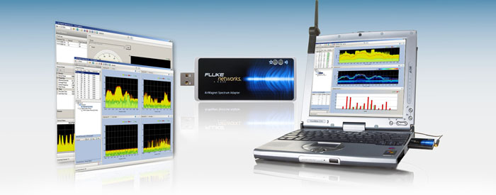
AirMagnet (www.airmagnet.com) AirMagnet is a division of Fluke Networks and has several products that also perform spectrum analysis. Figure 9.2 shows a USB form factor that can also be used on laptop computers. Because laptop computers no longer use CardBus or PC Card technology, USB form factors have become a must until PC Card Express adapters become more common.
Wi-Spy (www.metageek.net) Metageek also offers a USB-based spectrum analyzer, called Wi-Spy, which has gained a great deal of popularity. This product has traditionally been the lowest cost Wi-Fi spectrum analyzer that is popularly used. An example is shown in Figure 9.3.

Berkeley Varitronics Systems (www.bvsystems.com) Berkeley Varitronics also manufactures a handheld and tablet form factor spectrum analyzer that includes a full software suite such as the one shown in Figure 9.4. The benefit of this unit is that it is a dedicated device used primarily for spectrum analysis, but also has other Wi-Fi related utilities that assist in field troubleshooting and analysis.
FIGURE 9.4 Berkeley Varitronics Systems YellowJacket Tablet
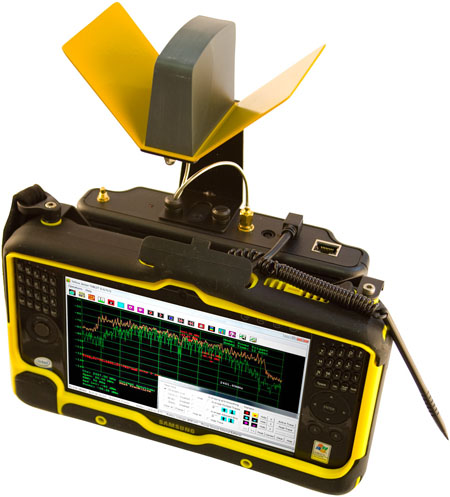
Courtesy of Berkeley Varitronics Systems, Inc.
Some of these products even integrate with survey mapping software or WNMS products. When devices detect abnormal signals that have known negative effects on Wi-Fi, they can send email or other alerts to staff.
Many full-featured spectrum analyzers often come with other important capabilities. One of the next most important features is network signal analysis, also referred to as a vector network analysis (VNA). It is beyond the scope of this text to discuss this topic in detail, so just keep in mind that a VNA becomes incredibly valuable in analyzing RF cables and antennas. A VNA will provide details of RF transmission lines, including return loss, impedance measurements, and detailed information to quantify antenna tuning characteristics. With the use of a VNA, you can quickly determine whether you have a bad antenna, RF cable, or connector.
Integrated Spectrum Analysis
In the past, Wi-Fi radios were not capable of capturing or reporting many meaningful RF statistics. The radio would detect and receive RF signals and report decoded information to the operating system of the host device. In that sense, WLAN chipsets were generally designed to transmit and receive IEEE 802.11-compliant transmissions.
That is what makes a spectrum analyzer so important. WLAN radios are affected by interference of non-802.11 transmissions but previously couldn’t report them, so without a spectrum analyzer you would be blind to RF interference.
WLAN chipset manufacturers are starting to incorporate spectrum analysis into their chipset designs. As of this writing, it is too early to speculate on the full capabilities that will be provided by integrated spectrum analysis. In the meantime, the feature quality looks very promising, though only a few vendors have implemented these solutions. Because WLAN radios are price sensitive, it is likely that dedicated spectrum analyzers will still be one of the critical items in a WLAN survey team’s arsenal. Without question, spectrum features in WLAN radios will never compare to the capabilities of the best dedicated, full-purpose spectrum analyzers. However, for many use cases, integrated spectrum analysis will provide a great deal of value.
The Physical Layer of Wireless
If you have a networking background, you are familiar with the OSI model. Layer 1 of the OSI model—in wired networking—refers to the physical cabling that is used between networked devices. In wireless, the physical layer is the wireless medium.
The use of “physical” might be a difficult concept to compare RF transmissions to. Just because humans cannot detect them doesn’t mean that they are any less real or physical in nature. In fact, in terms of thinking about RF and how important it is, physical is probably the best term to use in order for wireless professionals to grasp RF topics.
It is important to understand this concept as you will hear the wireless medium referred to as the physical layer in this book and other industry-related materials.
Interference with Patient Care
A hospital contracted for a new WLAN to be installed in their new expansion. This new area also incorporated the use of a patient telemetry system. As the new hospital wing was about to open and all the furnishings were installed, the WLAN team performed a survey to determine each AP’s placement. During that time no interference was detected when a spectrum analysis was performed.
The hospital continued to install and test each of the other systems for this expansion. As the new WLAN was installed, the IT team began to test the network performance and received incredibly poor performance. Their client devices kept disconnecting and they could hardly pass any data. After a great deal of lost time (several days), they called the site survey team back in and another spectrum analysis was performed.
What the spectrum analysis showed was an incredible amount of interference across the entire 2.4 GHz ISM band where their new 802.11g network operated. After tracking down the source of the interference, the team identified the culprit as the patient monitoring system (a.k.a. the telemetry system). The type of interference the system was transmitting was so severe that it would be impossible for a 2.4 GHz Wi-Fi system (or any 2.4 GHz system for that matter) to co-exist in the same area reliably.
The hospital staff then determined that the telemetry system they purchased was different than that used elsewhere in the hospital. It was the “new” version of the product, but unfortunately the staff didn’t realize this until it was too late.
In this case, one system had to move away from the 2.4 GHz band. The hospital decided to deploy an 802.11a solution operating at 5 GHz. However, this is a severely limiting factor for Wi-Fi and not all hospitals would have chosen this path. In fact, many Wi-Fi clients are not 802.11a or 802.11n (5 GHz) capable. The best solution for some would have been to return the telemetry system to the manufacturer for a system that doesn’t use 2.4 GHz.
When to Perform a Spectrum Analysis
Any time WLAN analysis or site surveys are being performed, spectrum analysis provides critical data about RF health that leads to WLAN performance. At least a minimal spectrum analysis provides a great insurance plan.
Some larger companies who depend heavily on their WLANs even install sensors that have incorporated spectrum analysis into their feature set. This provides a constant, 24/7/365 monitoring of their RF environment and can quickly report troubles to an operations team. Cisco’s 3500 series APs were the first on the market with an integrated spectrum analysis chip, which Cisco calls CleanAir technology.
Integrating spectrum analysis functionality with the AP radio might appear to have some limitations. This technology bets on your 802.11 network not being overutilized. In fact, most of the time APs are not transmitting and are able to collect a great deal of information and report the findings to a centralized database for later reference. One of the most notable benefits is having the ability to rule out highly impacting spectrum problems during troubleshooting events. If interference events are recorded in a database when they occur, this might also prove highly beneficial in determining the root cause after a WLAN outage has occurred.
Documenting Your Data
Whenever you perform a spectrum analysis, you always need to record the location where the measurements were taken, the local time, and any other activity or purpose of the scan. If a non-PC-based spectrum analyzer is being used, the screen shots tend to show the configuration of the instrument without having to record them manually. PC-based spectrum analyzers are generally nonconfigurable. Therefore, documenting analyzer settings for these devices is largely irrelevant unless you are using an external antenna.
Remember, spectrum recordings are location and time dependent. For example, looking at a recording a month later that simply says ACME Corp Recording 1 has much less value than one labeled as ACME-Location3-StaffBreakRoom-2.2dBiOmni-20100816-1454. In the second example, you know the location, which may even refer to a documented map indicating Location 3, the antenna type, and the date and time.
Locations can be documented in a column and row fashion by taking a floor plan and overlaying a labeled grid using letters on one axis and numbers on the other. In this case, you could label the previous example recording as LocationB3.
Regardless of the method you use, it is important to capture this information in order to make it useful when viewing recordings at a later date.
Some PC-based spectrum analysis products integrate with survey mapping software so that you can recall this data based on the exact location it was gathered from. The person performing the survey simply clicks on a map location and keeps moving. This process allows for the engineer to walk through a large area in a very short amount of time. An example is shown in Figure 9.5.

Configuring Your Wi-Fi Adapter When Performing Spectrum Analysis
One of the most common mistakes people make when performing a spectrum analysis is not disabling their WLAN radio from transmitting. While several PC-based spectrum analysis products rely on a laptop’s WLAN radio to detect 802.11 transmissions, the WLAN radio only needs to perform that task in listen-only mode. Some WLAN client utilities allow you to instruct the radio to not attempt to connect to any network, which essentially places the WLAN radio in listen-only mode.
If this is not performed, you will find very high-powered wireless transmissions in your spectrum recordings. The fact that a PC-based spectrum analysis chip is in such close proximity to the WLAN radio’s antennas explains why signal levels are registered at such high levels. When observing these high transmissions, it is not always obvious that they are coming from their own analysis station.
Disabling the WLAN radio on your laptop, for example, would also disable the ability to detect 802.11 transmissions for the spectrum analysis product.
Investigate the proper settings with your WLAN client adapter that enable you to suppress connecting to WLANs without actually disabling the adapter.
Using a PC-Based Spectrum Analyzer
Let’s now explore how to use a PC-based spectrum analyzer to analyze Wi-Fi frequencies; note that the base concepts are the same for all spectrum analyzers. We are focusing on the PC-based models in lieu of the others because they are the most commonplace and affordable varieties for design and survey tasks. Other types of spectrum analyzers certainly have their value, but for a field analyzer, there is nothing better than simply slipping an adapter onto your laptop to get you up and running. Many of you might even already be taking one of these with you just about everywhere you go.
In this section we will explore the types of measurements that you should pay the most attention to.
FFT
Fast Fourier transform (FFT) is a method of showing RF power as a function of frequency. FFT is the most commonly used function of a spectrum analyzer of nearly any kind. Any type of transmission that is heard on a specific frequency will be reported based on the actual signal level that was recorded.
FFTs are built by sweeping the frequency band. Usually three traces of particular significance are shown in an FFT:
Current The current trace is usually the default when a spectrum analyzer is launched. It is the maximum signal level reported over the measurement or display interval. For example, if a signal is transmitted at 2454 MHz, the analyzer reports the maximum signal level heard on that measurement interval even if the transmitter of the 2454 MHz signal only transmits once. If the analyzer swept that same frequency 10 times in a second and that was the highest RF signal it heard out of all 10 times, it would report that value on the FFT plot.
Average The average plot is an averaging of all the data points the spectrum analyzer recorded over a measurement interval. For example, using the same scenario as mentioned earlier, all the signal readings would be averaged and displayed in the same plot as the Current FFT trace, but usually as a different color for clarity.
Max Hold When viewing an FFT plot over time, the signal levels constantly change when viewing Wi-Fi network transmissions. Max hold is a trace that will keep a visual indicator of the maximum RF signal strength per frequency within a real-time FFT plot. It is a great method for viewing interfering RF signals in addition to Wi-Fi transmissions.
Figure 9.6 shows a PC-based spectrum analyzer using all three traces.
FIGURE 9.6 Real-time FFT from Cisco Spectrum Expert

Duty Cycle
When wireless devices transmit, they may do so in very short bursts like a Wi-Fi network, or worst case, they can send a continuous transmission such as with certain wireless video cameras. The amount of time a device occupies the wireless medium is measured in terms of duty cycle. In other words, duty cycle is a measurement of RF transmissions in the time domain (at a specified amplitude threshold or higher) rather than by signal strength, like with the FFT measurement.
Devices that use a 100 percent duty cycle are the worst types of wireless devices if you would like to share the same frequencies with other wireless systems. When a device transmits at a 100 percent duty cycle, you can also refer to it as a continuous duty transmission. This is important as a device occupying a specific range of frequencies that never stops transmitting makes it impossible for other devices to use those same frequencies. Remember, the 802.11 protocol utilizes a collision avoidance mechanism whereby it detects if the medium is available before it transmits. If the medium isn’t available, then a compliant device shouldn’t transmit.
Duty cycle plots can also incorporate the same current, average, and max hold traces that an FFT plot uses. Figure 9.7 shows an illustration of a duty cycle plot from a PC-based spectrum analyzer.
FIGURE 9.7 Duty cycle from AirMagnet Spectrum XT

Measurement Variables
Many PC-based spectrum analyzers on the market today have limitations on how the analyzer can be configured. Nearly all have fixed scanning behavior and bandwidth settings that cannot be adjusted. If you are not using a PC-based spectrum analyzer or one that may be adjustable for different measurement variables, you need to understand how they will affect the data values. Even if you are using an analyzer that has fixed settings, you should also know how to relate the output to other spectrum analysis measurements.
Sweep Times When a spectrum analyzer scans the RF medium, it begins at the start frequency and measures the RF in chunks of frequency as specified by resolution bandwidth, which we will discuss next. The analyzer continues to measure new chunks of frequency until it reaches the stop frequency. The elapsed time to scan a frequency range in chunks starting from the start frequency and ending with the stop frequency is called a sweep time. A slow sweep time will not provide reliable duty cycle measurements because it doesn’t get enough data samples of each frequency. It is important to understand sweep time when using any spectrum analyzer, whether or not it can be adjusted, in order to interpret the data properly.
In PC-based spectrum analyzers the speeds at which sweeps are accomplished are quite fast—so fast, in fact, that you can truly get a good gauge of duty cycle across a wide range of RF frequencies. This is something that is difficult to achieve across a wide frequency width with traditional spectrum analyzers.
Resolution Bandwidth Spectrum analyzers will measure RF in specific frequency widths. Therefore, when a spectrum analyzer is sweeping the RF medium it is reading the RF medium in chunks of RF as specified by a value known as the resolution bandwidth value. Resolution bandwidth is the actual frequency width that is used during a sweep cycle and affects the granularity of the RF information displayed to the operator.
Resolution bandwidth is usually not controllable in PC-based spectrum analyzers. In traditional spectrum analyzers, resolution bandwidth can be adjusted so that finer and finer frequency widths are used to provide a higher resolution of RF medium transmissions.
Dealing with Intermittent Interference
There are two kinds of RF interference that some would classify as the worst kind:
Continuous Duty The most notorious kind is one that is in continuous duty (it never stops transmitting) and therefore knocks out everything around it on that frequency.
Intermittent Interferer The other kind is the one that shows up unexpectedly and unpredictably, has a high enough severity to impact performance or reliability, and then goes away until yet another unexpected and unpredictable occasion. This type of interferer is called an intermittent interferer.
Months can go by when you are dealing with an intermittent interferer and you never find the source. This can drive you batty. One of the best methods to handle intermittent interferers is by using triggers. Triggers are configurable thresholds from which a spectrum analyzer will trigger a series of actions.
For example, assume an environment has an intermittent interferer and a spectrum analyzer is brought onsite. The spectrum analyzer can be configured to start a recording and perhaps even send an alert to the IT administrator when the duty cycle reaches past 50 percent for a duration of 5 seconds. Once that condition is met, the action is kicked off.
Triggers can be quite helpful in allowing an IT administrator to monitor an environment without having to sit and wait for the event to recur.
There are several types of surveys that you can perform. Some are better suited for certain environments or for obtaining different types of data. You will find that some people have strong feelings about one survey method versus another. At the same time, what you lose or gain from one method isn’t always self-evident. We will explore the different types in this section, starting with choosing the right client to perform a survey.
Choosing a Survey Client
Not all clients are created equally. If you’ve read Chapter 2, you should have a firm understanding of just how much clients differ from one another. When performing a WLAN survey, choosing the wrong client may yield an unusable WLAN design for inferior-performing devices in comparison to the client used for designing the WLAN. Grasping this fact is a critical requirement to be able to design enterprise WLANs.
It’s a good idea to make a list of all the critical and widely deployed client devices that will be supported on the WLAN. Next, try to obtain some data from spec sheets or other forms of documentation that detail transmit power and receive sensitivity. These two factors are the biggest variables in client device performance.
Of the clients that are to be deployed, the device with the lowest transmit power and worst receive sensitivity would be the best choice. Transmit power is more of a function of determining what the AP transmit power will be. However, assuming the AP’s power and client’s power matches, the receive sensitivity of the client makes the next biggest difference.
Detailed client specifications like these aren’t always easy to obtain. It is more likely that transmit power will be easier to obtain than receive sensitivity. If that is the case, a benchmarking exercise would yield the best results.
To benchmark your client devices, take an AP and set up a new SSID just for testing. This effort doesn’t require sending any data, so it can be an open SSID that isn’t even connected to a distribution system like an Ethernet network. Next, take each of your client devices to a fixed location that isn’t immediately next to the AP. In fact, we recommend that you have clear line of sight with minimal multipath and obstructions that produce RF signal reflections. This often means that an elevated position is desirable. For example, mark a spot where the client device reports approximately −60 to −65 dBm from one of the test clients. Going upward or near −70 dBm will likely kick off the roaming algorithm of the device and unpredictable behavior may occur, so it is best to not go where the signal is that weak.
Next, take a spreadsheet and record each of your devices at that same location in a similar orientation. Each client device data should be recorded in their normal use case. That means if it is a phone, place it on a person’s head. If two different laptop models use the same WLAN chipset, it is possible that the antenna design may be different, so it is best to also include device variations.
We also recommend that you record client uplink RSSI information, which is the value that the AP reports the client is connected at. Be aware that some APs average this value over a long period of time and you might need to wait a while in order for the averaging algorithm to weed out outlying data points. Consult your equipment vendor’s documentation to make the reporting value as real time as possible for this exercise.
When a device is connected to the test SSID, it is also important to turn off automatic RF management features so that the AP never changes power or channel. In fact, you should not use dynamic transmit power control (DTPC) if you also want to record uplink RSSI information. DTPC causes the client to change its radio transmit power based on information that the AP tells it. For example, if the AP reports that it is configured at 14 dBm, clients that support DTPC will also turn their transmit power levels to be in parity with the AP.
It’s a good idea to check each client device at different angles to the AP. For example, if you are using a laptop, stand in front of it to simulate how the device will be used in its real deployment scenario, and then rotate your orientation to the AP so that the laptop has a different orientation to the AP. Ninety-degree increments should do the trick. This way, you can help determine orientation variance to the AP.
Once this step is done, you should know your client device population quite well. When comparing the results of all your client devices, it should be apparent just how different their performances are from each another. Hopefully these client data measurements illustrate just how important selecting the right client is and how using different devices will result in very different survey data results. The best recommendation is to choose the worst performing client device that is supported by your survey application with which to perform surveys. This way you ensure that the network will support all of your client devices.
Keep in mind that most survey software packages do not allow you to use application-specific devices like VoWiFi phones, though basic surveying applications for some mobile platforms are currently available. You should also include in this client analysis a list of supported adapters that your survey software of choice also supports. Doing so will help you baseline your survey client adapter to the rest of your device population.
Survey Mapping Software
Until the day that glasses are invented that allow humans to see RF signals, we will need to visualize RF propagation using other methods. One of the best methods for visualizing RF data is to use a survey mapping software tool. This approach will import a scaled floor plan or map where the user can then associate RF data points to. Before these products existed, large CAD drawings were often used and RF values were handwritten manually onto these maps. That is a time-consuming process and makes it hard to visualize the results.
One of the first things you must do is calibrate the map. Calibration requires the user to measure a distance from two known points that are also identifiable on the map. The distance is then entered into the software to calibrate the entire map based on the known distance between those locations. Indoor environments that use drop ceilings are great because you can usually simply count the number of ceiling tiles and then multiply by the width of the tile. We recommend calibrating using long distances if possible, because the margin for human error is far less. Regardless of your method, once that is done the entire map should have dimensions true to real-world conditions that will allow the software to perform RF calculations.
Before data collection—the time-consuming part of a survey—we highly recommend that you confirm that the calibration was performed correctly. Take two other measurements and compare the results. If a calibration error occurred and it wasn’t caught, it is likely that the data gathered with an improperly calibrated map will be largely unusable.
Survey mapping software allows you to show a color overlay that corresponds to actual data measurements on top of a map, similar to what is shown in Figure 9.8. Maps showing a graphical representation of RF signals on top of a floor plan or map are also called heat maps.
FIGURE 9.8 Example of a heat map

When you are analyzing RF survey data, heat maps serve an incredibly valuable purpose for visualizing the RF environment as an overlay on a map. This allows you to quickly see where signal levels do not meet certain design specifications.
Propagation Assessment
In addition to the data points that will be taken during the surveying process, survey mapping software commonly uses RF algorithms in order to calculate an area around the measurement points and for other visualization purposes. In fact, there may be no algorithm involved at all and the survey software simply draws a bubble of information around each data point that matches the actual measured data. It is important to realize that it is the survey software’s guess. Some programs allow you to adjust the amount of guessable distance from each data point. If you are the one setting up the survey software parameters, you must determine how big this “guess zone” should be.
Keep in mind that the size of this zone in no way changes the actual data measurements. It is a visualization feature that makes the map look prettier. Improperly set propagation assessment distances lead more uneducated users of the heat map to assume that coverage might or might not be present in specific locations where no data was recorded, as shown in Figure 9.9.
FIGURE 9.9 Potentially misleading propagation assessment
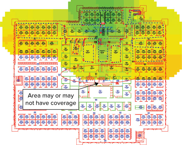
The area circled in Figure 9.9 is a hallway and the AP being measured is at the top of the map. The actual data measurements are based on the walking path where the dashed lines and arrows are indicated. In this case the propagation assessment was set to 25′. That means that in this case the SNR visualization will extend a bubble of color in a 25′ radius from a given data point.
Perhaps that hallway was made of a different building material or floor-to-ceiling metal filing cabinets full of paper were located against these walls. Would the signal propagate based on this assessment of 25′ as the survey software might predict? Assume that it will not. Unless a data measurement is made in a location, you cannot assume it will be covered unless you measured that location, which is why it is important to collect as many data points as possible for maximum accuracy. Minimize software guesswork when you can.
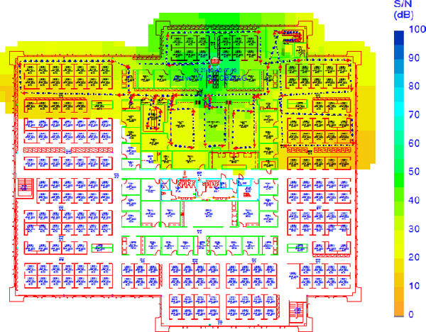
Compare this to the same survey, but when rendering the map using a 15′ propagation assessment, as shown in Figure 9.10.
FIGURE 9.10 Shorter propagation assessment

Spatial Orientation
Using survey mapping software requires a high degree of spatial orientation. When performing a manual site survey, some people struggle with tracking to the correct place on a map far more than others. You may find that you are one of those people. To complicate matters further, floor plans and maps aren’t always up-to-date and that can cause disorientation. This has nothing to do with technical competency. For people who fall into this group, it may take more time to perform a survey of this type than others.
Some devices aid with overcoming disorientation. Tablet PCs that can use pen-based input can be rotated as the surveyor turns in different directions while keeping the tablet in the same orientation as the physical environment.
Simulations
Some survey mapping software packages also have simulation tools that incorporate the known data points as well as the map calibration in order for WLAN designers to test modifications to their designs. These tools are particularly helpful in augmenting an existing design in which you were able to measure RF data points.
To gather data points, the surveyor will need to start in one area of a map and begin moving. As the surveyor walks, they click the mouse where they are walking on the map. Most mapping software automatically samples data points at regular intervals between mouse clicks. Therefore, every time the surveyor’s velocity or direction changes, they must click the mouse at those points in order for the automatic samples to be accurate. A good general rule is to record a manual data point approximately every 15′ or so. It is a general guideline, but realize that this is a safeguarding measure in case the surveyor has to retrace steps from an erroneous click, they are stopped in the hallway, or for a variety of other reasons. That means a minimal amount of resurveying will need to be done if steps have to be retraced.
Not all simulation tools are created equal—you usually get what you pay for in this category. To be clear, when we refer to the “wireless industry” it means more than just the 802.11 WLAN community. As a reminder, there are many other types of wireless communication, and some software is better suited for some technologies and use cases more than others. Simulation software is known to employ advanced RF calculations with a great deal of variable elements that an RF designer can tweak.
Passive Surveys
Passive surveys are surveys that are performed using a listen-only method. The survey client never associates to the AP. Such surveys can be quite helpful when you are looking for rogue devices or you want a good gauge of downlink RF coverage from the infrastructure devices. By downlink coverage, we mean the range of RF coverage that comes from AP transmissions. Passive surveys will be able to report downlink coverage and do not factor in any client uplink information.
Specifically, passive surveys listen for 802.11 beacons that come from infrastructure APs. Beacon frames are always sent at the lowest basic rate. Therefore, choosing 54 Mbps as the lowest basic rate on your survey APs will yield different results and range than a rate set to 2 Mbps. Lower data rates can be understood (decoded) at much further distances. We highly recommend that you use the same radio settings that you would in your production network.
Again, it is important to remember that passive surveys only provide information of downlink coverage from your WLAN infrastructure. APs that are set to very high or very low transmit powers can provide a skewed perspective of the network.
Convenience is your biggest gain when conducting passive surveys. There is less complication, and regardless of the security policy used, you will be able to perform a site survey.
Use passive surveys when you are trying to accomplish the following:
- Find rogues
- Locate RF trouble zones quickly
- Validate final RF settings
- Validate a network that uses enterprise security
- Perform initial surveys (caveats apply)
Methodologies of a Passive Survey
Passive surveys are used for a variety of purposes. Analyzing an existing network is one of the most common use cases. Passive surveys can quickly reveal areas of low or too much signal based on current settings. As mentioned earlier, the results can be dangerously misleading if the transmit power of the infrastructure is unknown or improperly configured.
Another common use of passive surveys involves the use of finding rogue APs. In this approach, configure the survey software to scan all possible 802.11 channels. That way, if a rogue AP was installed, a passive survey will most certainly catch at least one beacon from the AP when it scans each RF channel.
If you are using passive surveys to perform site surveys for new WLAN deployments, pay careful attention to detail. First, the transmit power of the survey AP must be reasonably low. We recommend that you use a transmit power that is close to or at the lower range of what you will want to support in your production environment. Specifically, this means that the AP transmit power should not exceed the maximum transmit power of your least powerful client devices. Another consideration is to not misconfigure your AP to exceed regulatory power constraints for the area where you will be operating your WLAN.
Client channel scan settings are another area where mistakes are commonly made when performing site surveys for new WLAN designs. If your survey AP is on channel 1 and your survey client is scanning all channels, you will not have usable results with which to gauge your WLAN deployment.
Optimizing Channel Scan Settings
When performing a passive site survey, usually the default settings are to scan all 802.11 channels. To help quantify this, assume that all 14 channels for 2.4 GHz ISM are scanned, plus all of the 24 channels for 5 GHz UNII and ISM. Next, the dwell time the survey radio will spend on each channel is configurable. The default in AirMagnet Surveyor is 250 ms because it needs to pick up at least one beacon for each AP on that channel, which is usually a default interval of about 100 ms. Ideally, more than one data sample is preferred before changing to the next channel in order to help mitigate against multipath and RF nulls.
In this case, that means a total of 38 channels are scanned. Therefore, only 1/38th, or 2.6 percent, of the time is spent analyzing a given channel. In other words, assuming 250 ms is spent on each channel, that would yield a total of 9.5 seconds to sweep through all the configured channels. A lot of physical ground can be covered within about 10 seconds. Assuming that your environment doesn’t use all these channels and you are not looking for rogue devices, you will need to optimize the survey software to eliminate looking at those channels. In other words, if you are trying to analyze your WLAN infrastructure and it only operates on a subset of those channels (usually a small subnet), you will not achieve the results you might expect.
Another consideration when performing a passive survey is that you want to turn off automatic RF management features at least during the survey—that is, unless you want to validate that the automatic RF features are doing their job correctly. The reason you might want to turn off automatic RF management features is because you do not know what the AP transmit power is set to. Even if you recorded a snapshot of the network’s values, they can still change at any time. Regardless, it is still an exercise to manually determine the AP transmit power when you have to analyze the survey results.
If you surveyed an environment, say, at 25 mW and based your AP placements using sound methodologies, it is hard to imagine that it would ever make sense for an AP to go down to 1 mW or perhaps even up to 100 mW. In both of these cases, problems will likely occur. Specifically, if coverage is based on 25 mW and you measured that it provided coverage into nearby rooms and areas where clients will reside, turning it down to 1 mW made your network unusable at the extents of its original coverage. Conversely, if the AP went to 100 mW, it is likely that you may have WLAN clients that aren’t capable of that power. So, you get the megaphone on the hill analogy where clients can hear the AP, but the AP can’t hear the clients back. Remember, transmit power doesn’t change receive sensitivity; it only changes downlink coverage and what you are striving to achieve in WLAN designs is symmetry in the RF link. Of course, high transmit power could also create a co-channel interference problem too.
The point should be clear here that passive surveys can get you into trouble if you do not consider these variables.
Most site survey software packages do not work with enterprise WLAN security. While some offer support for certain EAP types, we highly recommend that you avoid all forms of WLAN security. It complicates the initial configuration of your survey and you are only concerned with RF coverage. If you need to analyze WLAN security, make that a separate task so it doesn’t complicate the RF analysis. Furthermore, WLAN security should only be tested on the actual clients that your network will use.
Greenfield Deployments
One method of performing site surveys for designing new, or Greenfield, installations is to use a passive survey. If done correctly, this survey can result in time savings. In this approach, the survey AP is placed where the surveyor believes an optimal location is and the survey utility is configured to scan only that channel. The AP is configured to broadcast a survey-specific SSID regardless of the security type being used. Without even concerning yourself with security settings of the AP, as long as the AP is broadcasting an SSID, the client will be able to gather what it needs. Remember, beacon intervals are set to approximately 100 ms, so that will yield approximately 10 data samples per second, which is pretty darn good.
It is possible to expand this process to multiple APs. This means that you can take a second AP and configure it for the same or perhaps a different channel. It is usually best to use the same channel so the survey client never needs to change its channel. If another channel is used for the new AP, you should set your survey utility to scan only the two channels the survey APs are configured for. Failure to do so will result in the channel scanning phenomenon mentioned earlier where it will receive only a small fraction of information from the APs you are surveying.
This method requires caution. Placing APs either too close or too far away might not be evident until you have started or even finished your survey process, which would require you to start the survey all over again. If you choose to use this method, it is very important to walk to the extents of where you are trying to obtain coverage with your survey client to determine if any location changes are required before you begin to record data. Doing this for two APs certainly will add some time to each initial AP setup, but you need to take this into account if you believe it will save you time in the end. For those who do not have a lot of experience performing surveys, we don’t recommend this method. In fact, there is a lot of room for error using this approach, but it is still a viable alternative.
What You Lose When Using Passive Surveys
The most significant loss of information with passive surveys is uplink information, PHY rate boundaries, and retransmissions. As you have already learned, PHY rates are generally based on RF signal and noise levels. A passive survey will only report signal propagation for beacons measured by the particular client device used to perform the measurements.
PHY rates can only be measured by sending actual data to and from an AP. PHY rates are also good indicators of RF signal health and balanced link budgets. For example, if an AP’s transmit power is set at the maximum level, the passive survey will show a very large coverage area. What it wouldn’t show is the usable subset of that coverage area by your least capable client devices. If a client device can only transmit at half the range of the AP, it will result in a client’s inability to connect reliably to the infrastructure. PHY rates and retransmission information can be a useful gauge in comparison to purely downlink information.
Active Surveys
Active surveys are surveys performed with the survey client associated to the APs used during the survey. When a client is associated, it performs all the tasks a typical 802.11 client performs, which includes shifting data rates as RF conditions change and performing retransmissions when it determines that the AP did not hear the transmission. This information is incredibly valuable in order to highlight network problems.
Active surveys are commonly used for new WLAN deployments because they provide the most amount of detail to base a design on. Unless you are doing multiple APs at a time, it takes roughly the same amount of time to perform an active survey as compared to a passive one. Active surveys also benefit from reducing human error during the survey process. When performing an active survey, the only critical component to the survey equipment configuration is AP transmit power settings.
Use active surveys whenever you are looking to understand more information from your surveys. Having PHY rate and retransmission information tells you much more about the environment and the ability for a client to communicate back to the AP. Additionally, knowing how far your APs will propagate is useful information for a variety of purposes.
Active surveys are also recommended for less experienced survey teams because they can reveal and help to eliminate human error. They allow the person performing the survey to see the full coverage that a single AP provides that will most easily guide them in placing the next AP.
Some people refer to active surveys as “AP on a stick” surveys.
Methodologies of an Active Survey
There are two main methods for performing active surveys: the BSSID method and the SSID method.
BSSID Method
The BSSID method of an active survey is the most common of the two methods. This method locks a client into an AP’s radio MAC address and prevents the client from roaming. This gives you a full picture of an AP’s connectivity zone along with a rich amount of performance detail.
When this method is used, each individual AP can be analyzed, allowing a surveyor to show the complete RF propagation pattern and PHY rate zones. This information is, of course, based on the survey client type being used for the survey.
In Figure 9.11, a map of an active survey using the BSSID method was used. As you can see, different aspects of the data can be viewed—in this case, the actual PHY rate measured by the survey client.
FIGURE 9.11 PHY rate map
In Figure 9.12, the same map is shown but this time retransmission data was used. This map is a good gauge of performance and of spectrum interference. You would expect to see a large amount of retransmissions at the edges of coverage when using the BSSID method. By definition, you are asking your survey client to forcefully lock into the AP you are surveying, so it will continue to retry each data transmission until it is successfully heard or the client disconnects. It is likely that standard 802.11 clients will trigger the roaming process if excessive retransmissions occur. This map usually indicates the areas where clients will roam away from the AP being surveyed. Note that PHY rate shifting usually occurs once an 802.11 station starts to experience retransmissions. Therefore, you can expect to see an increase in retransmissions at rate shift boundaries.
FIGURE 9.12 Retransmission rate map

Human error may also be reduced when compared to passive surveys. In an active survey, the surveyor does not need to pay attention to channel scan settings in the surveyor client. The software will find the AP and stay there until the survey is stopped.
SSID Method
The SSID method of an active survey is used for surveying multiple APs and is more commonly used for postdeployment scenarios. This method enables the survey client to associate to an SSID where the client will roam between multiple APs. Some survey clients let you adjust the roaming thresholds for when the client will decide to roam. The SSID method is the closest example to real-world client roaming conditions of all the survey methods.
There are some limitations to using this method, including the loss of some visibility to the full RF propagation of each AP. In other words, you lose visibility to where acceptable coverage might begin and end for each AP. This is due to the fact that when the client leaves an AP and roams to another, it loses all visibility to the one it just left. Furthermore, if a client has acceptable coverage from an AP it is already associated to and it moves into a zone of another AP that is spaced too closely, it will likely not roam to that new AP until acceptable coverage degrades past the point where the surveyor client has instructed it to roam.
Another limitation to using this method is that roaming triggers used in the surveyor client likely do not mimic real-world conditions with standard WLAN clients. Therefore, it is not necessarily an accurate gauge of how your network and client devices will perform.
Conceptually, this method does have some value in helping to see how certain client roaming settings might perform on your network. Therefore, this method is largely used to augment other survey methods used, but usually does not serve as a replacement.
Security Limitations
Performing active surveys involves a full 802.11 association, which includes needing to configure WLAN security. This may be a problem when performing postdeployment coverage validations. Some survey software packages allow you to configure WLAN security, but often there are severe limitations on EAP types and compatibilities.
Simply put, it is best to avoid all security configurations when performing surveys using survey mapping software packages. The best option is to configure a temporary SSID or use a guest SSID (if one exists). On this temporary SSID, you can usually add a firewall rule to prevent all traffic from hitting the Ethernet network, if the AP is connected to the network. Otherwise, depending on the survey software package, using a WPA PSK key might be an option.
What You Lose When Using Active Surveys
With active surveys, the only thing you really lose is rogue or misconfigured AP information. Because the 802.11 client is actively associated to a BSSID it is not constantly changing channels hunting for APs that might be misconfigured or considered rogue.
Depending on what you are trying to achieve, it is usually best to perform a quick passive scan of all channels before performing an active survey. Passive scans of this nature consist of simply walking major areas of a coverage area. For example, if the environment is a university, it would be sufficient to walk the hallways doing a passive scan of all available channels. This process will find any AP that is transmitting beacons.
Virtual or Predictive “Surveys”
In the 802.11 industry, there are certainly a variety of contentious topics that are debated among professionals, not the least of which is the topic of virtual, or predictive, surveys. A predictive survey is a survey performed using a software program and an operator that is programming the tool with information about the coverage area in order for the software to perform AP placement based on RF algorithms. These surveys are typically void of any type of field measurement. From a business perspective, the gain is obvious: time and money. The problem is that if a predictive design is a bad design, the upfront savings of time and money are lost. In fact, recovering from a bad design can result in a substantial amount more money, and time, than would have been the case had the design been done right from the start.
Using the term survey for a completely software-based exercise is a play on words to some extent. Webster’s Dictionary defines the word survey essentially as the act of taking measurements using analytical and mathematical methods. Predictions, although based on mathematic principles, do not factor in the unknown and real-world variables that exist. Many have argued the use of the word survey related to this method.
Environments that have critical dependencies on WLANs should not employ predictive surveys. This method should be reserved for environments where best effort performance is required. Predictive surveys also have value for budgetary planning purposes.
Another use of this method is when the building does not yet exist. In other words, you cannot survey an environment that hasn’t been built, so you essentially have no alternative other than to perform a predictive survey—that is, unless you can wait until after the environment is built. If the target environment will critically rely on the WLAN for certain activities, including a heavy reliance on seamless roaming, it is indeed recommended to wait. Examples of these types include areas where VoWiFi will be deployed and places like hospitals with highly mobile devices and staff members with mobile devices. Otherwise, a predictive survey can get you mostly there and you can later perform a postanalysis of the network once it is installed and the environment is fully populated with furniture and other items that might affect RF propagation.
It is often best to pull additional cable drops and purchase additional APs whenever a predictive survey is used. This will more easily allow for altering the design based on the postvalidation survey.
The best times to incorporate a predictive survey are as follows:
- When the deployment environment hasn’t yet been built
- To obtain a budgetary estimate for WLAN-related hardware
- When roaming requirements are less stringent
- When tolerance for less-than-perfect coverage is less critical
There is value to a predictive survey, but in practice, few environments have reliable enough information to base a predictive survey on. In addition, many facilities have less-than-accurate CAD drawings, a fact that adds even more complexity to the equation.
Approaches to Conducting Predictive Surveys
Predictive surveys involve complex software tools that are designed to import CAD drawings of the intended deployment environment. The basic concept is that you inform the software about certain characteristics of the environment based on the imported drawing. For example, you would specify the type of walls that are in the environment and the type of construction used. Walls that are made of concrete have higher attenuation than do walls made of sheetrock with wood or metal studs. Effectively, the knowledge of the person (operator) informing the predictive software tool about the environment is the single biggest factor for success. If there is a lack of detailed information available to the operator, then the results will be less reliable.
Calibration of a predictive modeling tool is absolutely essential. The software uses algorithms based on free space path loss (FSPL), the information that the operator provides to the software, antenna type, and transmit power to predict locations for each AP.
The operator must also have knowledge of the deployment environment—perhaps even more so than someone who has the ability to visit onsite. For instance, the software tool might not be able to factor in atriums, areas of high aesthetic concern, mounting options, mounting height, antenna types, cable length limitations, and many other factors that can render certain locations not deployable.
It’s possible for a predictive survey tool to incorporate measured RF propagation information in the environment. If you place a single AP in an environment and then walk the area and measure using a survey client, your software could incorporate that information into its prediction process. In fact, this method would be much less of a prediction because it incorporates this RF fingerprinting data.
If predictive modeling will be used, this is the recommended method. Take actual data samples from the deployment environment and use those RF propagation characteristics to calibrate the modeling software. In other words, use the real-world measured data to recreate the propagation characteristics in the software. This is a useful method for large deployment environments and allows for semi-accurate calculations. The actual deployment will require fine-tuning, if not more substantial changes, of AP placement, but the predictive approach will provide a useful framework. This survey method is often paired with dynamic RRM functionality.
What You Lose When Using Predictive Surveys
Whenever you are asked to perform a predictive survey and the use case doesn’t fall into the categories we discussed earlier, you should ask your customer to reconsider.
When deciding to use a predictive survey for a WLAN design, you generally get exactly what you set out to achieve: a prediction. Nearly all WLAN experts with a respectable amount of field experience would agree that nothing beats actual field measurements and data on which to base a WLAN design.
There are so many variables that will affect RF propagation. Anybody who has performed a substantial number of surveys in a variety of environments can probably tell you a number of stories of just how hard it was to get ample coverage in certain parts of their projects. How RF will perform in a real environment is not easy to predict.
In short, you can lose a lot with a predictive RF survey, but these surveys still have their place and value proposition. Consider your choices wisely and predict what the consequences would be in both time and money (and to your reputation) if the design doesn’t meet the requirements for proper performance, up to and including VoWiFi applications.
You must inform and educate your customer accordingly when you are asked to perform a predictive survey by using the information and caveats listed here.
Postverification
Based on the proper applications of when to use a predictive survey, you should also include a thorough postverification analysis of the network once it’s installed. Chapter 14, “Post-Installation Validation,” delves into methods for properly performing this task. Post-installation surveys are probably the most important aspect to all surveying approaches. You must verify that your design and deployment actually works for the actual clients that will be used. This is key.
The interesting part of RF is how it penetrates through opaque materials. As humans, we tend to think about things in terms of light and how light stops when anything opaque stands in front of it thus creating a shadow. For example, television remote controls use Infrared light, which is why they do not work when pointed away from the television. While some good analogies of light may be used when discussing RF principles, it fails to compare on many other aspects. RF is vastly different from light because it has the ability to pass through walls, floors, and a variety of other objects. This includes in two-dimensional spaces as well as three dimensions. Three-dimensional RF propagation can be both a hindrance and a benefit.
RF can reflect, refract, and scatter off a variety of materials. Placing antennas near certain objects can change the tuning characteristics of the RF performance of those antennas—in a two-dimensional as well as a three-dimensional plane.
Simply put, RF propagates between floors—so much so in some environments that an AP on the floor above (although usually below) can provide enough coverage to service a sizable area of floor space below. It all depends on the building construction, the antenna types used, the mounting location, and antenna placement. Older construction techniques have tended to use strong and thick interior walls in multistory buildings for additional structural integrity. This type of construction limits a company’s ability to reconfigure the floor based on its business needs. Architects and builders have learned this over the years and generally use building techniques that have strong floors with lightly constructed walls to allow for reconfiguration of the space based on future business needs.
From an RF coverage perspective, you may find yourself seeing much more floor-to-floor propagation in older construction than you see in newer or similar construction techniques. Floor-to-floor propagation will, without question, affect performance of the final design solution. For example, if you were to stack APs on top of each other from floor to floor, that arrangement will usually maximize the stacked APs’ ability to hear one another. Configuring these APs for the same RF channel can have a significant impact on performance. This is not a desirable outcome.
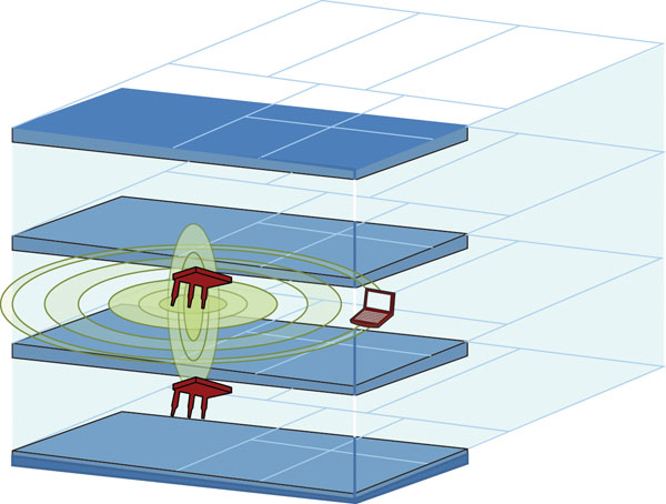
What is likely to occur is the APs hear one another’s transmissions to their associated client stations, but they do not hear the client station return transmissions especially if a client is directly above or beneath an AP on a different floor. This situation will usually invoke a common RF phenomenon called hidden node. Hidden node is most commonly drawn from a 2D perspective, but when you consider it from a 3D perspective, it makes the possibilities for hidden node even more real. Figure 9.13 shows a simple illustration of an AP that is able to communicate with a mobile device on the same floor using the same channel as an AP placed on the floor below it. The transmissions from the AP back to the client are also heard by the AP below it, resulting in interference and corruption from hidden node transmissions.
FIGURE 9.13 3D RF propagation
Understanding RF Propagation
Passive surveys are excellent for helping you gain a solid understanding of RF propagation between floors. Of course, they will only work if the APs are installed, which is arguably too late in many cases. Therefore, multifloor RF propagation needs to be factored in, and quantified, during the initial RF survey designs.
In general, you should take spot measurements at different locations in a facility from the floors above and below an AP placement. Because it is cost prohibitive to perform this measurement for every AP placement, and you are hoping to gain a perspective of the propagation between floors, you should perform this activity only where construction methods and periods are different. For example, parts of a facility that have been expanded over the years most likely have different floor-to-floor signal bleeding than parts constructed during earlier periods. This information, in essence, tells you to what extent you need to worry about floor-to-floor stacking of APs. Alternatively, this information might help you design for signal propagation in some parts of a facility.
In general, signal bleeding through floors produces a small geographical area of acceptable signal coverage. In this case, you should not rely on this coverage for applications like VoWiFi or where devices are highly mobile. When in motion, a client device might roam to the floor above or below, and as the device continues to be in motion, it will then quickly roam out of its acceptable coverage area. The result would be two quick roaming events, which might cause a perceptible delay in service. This same phenomenon is similar to APs that are powered down to the lowest of extremes.
In other instances where roaming activities are minimal or devices are stationary, this 3D bleeding might be factored into a design. Multifloor coverage applies in certain situations where two AP coverage patterns meet and a device is stationary. We don’t recommend that you rely on multifloor coverage, but it is just another tool in the toolbox for certain corner cases.
The important thing is to familiarize yourself with the negative effects of multifloor propagation and be able to quantify how much it needs to be factored into your design. It is always best to quantify this aspect by performing at least a few measurements. Special areas like atriums, outdoor areas adjacent to multifloor buildings with deployed APs, and similar types of cases are obvious areas of concern.
RF Propagation in Atriums
A good rule of thumb when dealing with atriums is to not place APs too close to the walls of the atrium when providing coverage to adjacent (non-atrium) areas. APs placed in an atrium will usually propagate quite far, and if the signals of APs placed in other parts of the coverage area do not propagate into the atrium, this means that explicitly placed APs in the atrium can provide the best, contention-free coverage to clients also located in the atrium. We generally recommend that you use directional antennas in atriums to maximize the coverage in the atrium while also minimizing the propagation into the adjacent areas.
Floor-to-Floor Placement
In general, avoid stacking APs directly on top of each other between floors. Depending on the type of antenna used, the propagation pattern might be minimal directly above and below, and in those cases it is certainly acceptable. In some cases it may be unavoidable due to mounting or cabling restrictions.
It is best to place APs in a staggered fashion between floors. Where two AP cell edges meet on one floor, you should place an AP directly above and/or below that spot on neighboring floors. Doing so can help protect against coverage gaps should construction or other factors change in the environment that affect the original propagation from APs. In this case, 3D RF propagation can help a design be more resilient to changes over time.
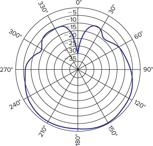
Most enterprise APs that incorporate internal antennas tend to be designed to be mounted to a ceiling and provide coverage somewhat similar to a low-gain patch antenna. The signal is somewhat of a carotid pattern from back to front. Figure 9.14 is an example of an enterprise AP coverage pattern that is heavily used in the enterprise.
FIGURE 9.14 Elevation plane (2.4 GHz) propagation pattern of a Cisco 1142 AP
Channelization
As you may have already determined at this point in the chapter, channelization should be based on floor-to-floor propagation from all the APs in an environment. If you are not planning on using an automatic channel assignment algorithm, you will need to rely on your survey information to best assign channels based on multidimensional information.
Most new deployments of any scale will likely have automatic RF algorithms built into the infrastructure. If this is the case, you may find that you might experience some unexpected results. In some cases, you might find that several immediately adjacent APs on the same floor use the same RF channel. Although this situation may not seem ideal, it is often likely due to multifloor RF propagation. What the channelization algorithm is likely doing is configuring different channels for each of those APs based on its hottest RF neighbors. Therefore, from the perspective of each of these APs it is likely that they are hearing APs from floors above and below hotter than the adjacent APs on the same floor.
This arrangement yields, from the perspective of the AP, too many RF neighbors for the channels it has available. Too many neighbors and too few channels to pick from is especially true when you’re using the 2.4 GHz ISM band where only three nonoverlapping channels are available. In this scenario, it is important to either trust the algorithm or consider redesign efforts. After all, the algorithm is based on the most important metrics.
Utilizing Infrastructure Links
Infrastructure links in the context of this discussion pertain to point-to-point (PTP), point-to-multipoint (PtMP), and mesh AP RF links. Typically these are APs installed in outdoor environments that bridge computer networks or devices in multiple locations. Mesh links, in particular, are generally used to extend the range of an RF coverage area where a network backhaul connection is not feasible.
These types of infrastructure links can often travel great distances. The following is usually the case: the longer the distance that needs to be covered, the higher the antenna gain that must be used at each side of the link. As you increase the amount of antenna gain in an infrastructure link, the alignment of these antennas can be quite a challenge. Let’s now discuss infrastructure links in detail.
Point-to-Point Links
PTP links usually travel the farthest distances of any of the infrastructure links we’ve mentioned. By definition, they involve a device dedicated to each end of the RF link that speaks to one and only one RF peer. Because of this fact, you will find a special breed of APs, called bridges, that are designed and marketed specifically for these applications. The term bridge is overused and can be interpreted as many different technologies in computer networking. In the wireless world, using the word bridge by itself is usually interpreted as a PTP link device, but we recommend that you refer to them as a PTP bridge in order to be more specific.
Because PTP links are designed to speak with only one peer, it is quite common to see them sold or packaged in pairs. When they are not, it is often because the manufacturer has a variety of options for each bridge, such as internal or external antenna ports, different types and quantities of wired ports, powering options, and so forth. It is not uncommon to have to spec different, but compatible, model numbers for each end of the PTP link.
Compatibility is an interesting topic when it comes to PTP bridge links. A standards-based, multivendor protocol is not required. When you are using a device for such a specific use, a manufacturer tends to optimize a standards-based protocol like 802.11 with certain proprietary tweaks to gain performance and stability. Such tweaks may include delaying the standard ACK times because of the time involved for RF propagation to occur over distances and the response to be provided back to the transmitter. If you need to travel far distances, it takes longer and longer for the RF transmission to travel that distance. Channel bonding (increasing the frequency bandwidth) is another common technique by PTP bridge manufacturers to gain more data throughput. Other areas of tweaking include different modulating and coding schemes, contention algorithms, and QoS prioritization. The PTP link doesn’t even have to use RF at all—some companies use lasers and other mediums as a form of optical, long-range communication for the same purpose. We always recommend that you avoid mixing different vendors with PTP links.
PTP links are often used as a replacement for a physical data circuit that comes with a high monthly recurring price tag. They are also used as a means of increasing data throughput to an existing set of circuits where IP routing protocols can load-balance traffic across. Using PTP links for this purpose usually provides a great deal of cost savings and perhaps a big increase in speeds with reduced latency. Even buildings that may be located close to each other may use PTP links in lieu of trenching the ground, running conduit, and installing fiber-optic or copper cabling. A great deal of labor and cost is involved in this effort. While wired connections have some benefits, using PTP links provides a cost benefit and they can even be used for relatively temporary installations.
What if you don’t have LOS between the two PTP links? Usually no LOS spells disaster. Many RF links have still been made even with this deficiency. Typically success is achieved only by using the lowest frequencies possible—which explains why you still see many 900 MHz ISM band PTP products on the market. The speeds that are possible using 900 MHz are less than the higher frequencies, but the lower frequency can penetrate through many more obstructions, and therefore products using this band still have their niche in the marketplace.
Alignment
One of the hardest tasks when dealing with PTP links is getting the proper alignment. While this is usually a problem attributed to longer-range links, sometimes even shorter-range PTP links present a challenge. As you’ll recall from our discussion of antennas in Chapter 7, “RF Hardware and 802.11n,” achieving higher antenna gain means that the RF signal is reduced for other directions. So, the higher the antenna gain, the higher that directionality of the antenna. Additional RF isn’t manufactured from higher-gain antennas; it is just that higher-gain antennas shape the RF signal to the particular antenna pattern.
When using high-gain antennas for PTP links, you’ll find it difficult to align over long distances where you may not even be able to see the other end of the link. Here’s a good parallel: pretend you are five miles away from a colleague at the other end of a communication link and you are both holding a laser beam. Imagine trying to align both laser beams at each other perfectly. Both sides must be properly aligned for a functional communication link.
This is only an analogy and no antenna gain manufactured at this time has a beamwidth that small. However, a 24 dBi parabolic dish or grid antenna only has a horizontal and vertical beamwidth of approximately 10°. That is an extremely tight beamwidth to align over long distances.
One way to get around this issue is to use a high-gain antenna on one end of the link and a lower-gain antenna (15–19 dBi) on the other, as shown in Figure 9.15. This method allows for very high gain in the link budget without complicating the installation and tuning process.
FIGURE 9.15 PTP link with lower gain antenna on one side
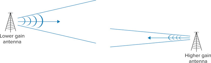
In fact, there are many stories of installation professionals who have spent a day or more trying to align very high-gain antennas at each end of a link where they knew RF LOS was possible.
When you use a lower-gain antenna on one side, it may only reduce the overall link budget by a number in the single digits. At the same time, the antenna can move due to wind (on top of a tall mounting pole or radio tower) and will still maintain a solid link.
Another point to keep in mind is that, by definition, using a lower-gain antenna has a wider propagation pattern. The result may be that other unwanted RF transmissions that are in range of the lower-gain antenna are introduced. For example, if the lower-gain antenna is mounted on top of a roof where APs using the same channel are installed, the lower-gain antenna’s pattern may include these APs in its primary propagation pattern. That will cause transmission hold-offs on PTP links transmissions because, as you’ll recall, we are using CSMA/CA or collision avoidance techniques.
If that is the case, you should consider on which side of the link it may be best to place the lower-gain antenna. Perhaps only one side of the link has this issue. An example of this technique would be to use a 24 dBi high-gain parabolic dish on one side of the link but a lower-gain 15 dBi yagi antenna on the other.
Polarization
The polarization of an antenna is defined as the E field, or electric field. When the E field is vertical, the polarization is said to be vertically polarized. Alternatively, if the E plane is parallel to the ground, the polarization is said to be horizontal. If you look on the back of most directional antennas, the direction of the E field is usually marked with an arrow. For additional clarity, refer to the manufacturer’s documentation for the antenna you are using.
Antenna polarization becomes much more of a design factor over longer distances. If antenna polarization is incorrect, the signal may not be strong enough to maintain a reliable signal for the PTP link. Be certain to use the same polar alignment for both sides when using PTP links. Figure 9.16 illustrates one antenna using horizontal alignment and another using vertical alignment.
FIGURE 9.16 Antenna polarization misalignment
Antenna polarization might be a technique you want to use when trying to avoid interference from other RF transmissions. One polarity might be better than the other and you can make this determination during a PTP site survey.
Survey Methods
The first step in a PTP link survey is to get absolutely everything working perfectly in the comfort of an office with the equipment placed nearby each other. Doing so saves you a great deal of time in the field configuring the units and eliminating configuration from the troubleshooting equation. Even after doing so, you must save the configuration to the flash memory or equivalent of the radio and perform a full power-down and power-up to ensure the changes stuck.
While you may need to change RF frequency of the link during the survey depending on RF conditions, this task is extremely minor in comparison to configuring everything from scratch.
When performing a survey for a PTP link, come prepared with an entirely different arsenal of tools than you might need for an indoor survey. You will need the following:
- A variety of gain and types of antennas, including very high ones
- Antenna cables and connector adapters
- Binoculars, a spotting scope, or a telescope
- Mirrors
- Accurate GPSs
- A compass or sighting compass
- A level
- A protractor
- Tape or chalk for marking alignment
- Mobile phones
- A laptop computer
- A Wi-Fi radio or PC-based spectrum analyzer with an external antenna connector (if applicable)
A common technique is to start with lower-gain antennas and build your way up. For example, one side of the link can start with a 15 dBi antenna coarsely pointed using GPS coordinates and a compass for alignment. The other side of the link can also use a 15 dBi antenna using the same technique for coarse alignment. This method allows for a very wide tolerance of error usually in both the vertical and horizontal alignment.
Always perform a PTP RF survey using two teams of people. One team (or person) needs to be at each end of the PTP link.
Assuming you’ve done your homework and you have the coarse alignment correct, you may be able to establish a link. In situations such as longer-range PTP links, you may need higher-gain antennas to establish a link. Lower gain antennas will steal signal from the RF link budget. In that case, you may have to start with a higher-gain antenna at one side of the link. If you need it for both, perhaps a PTP link is questionable to begin with because you shouldn’t be operating with such a small margin in your link budget.
Remember, even a low-quality RF link from the PTP peers is enough to start optimizing the alignment and antenna choice.
The coarse tuning method is sometimes referred to as prealignment. Prealignment may also be performed using other techniques incorporating the materials we’ve mentioned. For example, mirrors have traditionally been used to reflect the sun from one side of the link to the other. You’ve likely experienced the bright sun reflected back to you from a mirror. It is quite noticeable even from very far distances.
Other methods include using binoculars, spotting scopes, or telescopes to see the other end of the link to get coarse alignment. Spotting scopes and telescopes can be quite nice when used with tripods because they provide a visual point of reference for the coarse antenna alignment.
Using Optical Scopes
One of the authors received a phone call from a colleague who was performing a PTP radio installation at a job site. The colleague, Joe, said that he had an interesting story to relate. So, he began to explain by describing the environment and the fact that the antennas were separated by a distance difficult to determine by the naked eye. He commonly carried a spotting scope for such purposes.
In order to perform the work, Joe explained to the employees of the facility that he would need to be on the roof of the area, and he asked the employees to alert the security staff. But during his coarse alignment activities, Joe was interrupted by a team of officers with armed weapons pointed directly at him. Because the environment was an airport, the use of the spotting scope on top of a roof overlooking a runway of taxiing aircraft while he was in a prone position didn’t sit well with the airport police.
Hopefully you will never find yourself in this predicament, but be aware that it might be best to request an escort for some environments.
After the coarse alignment is performed, you can then start to fine-tune the alignment. One technique is to find the center of the pointing direction. Here’s where marking tape and chalk come in handy. Take one end of the PTP link and, reading signal levels from the PTP radio, move the antenna all the way to either the left or the right until the signal degrades rapidly. Repeat this exercise several times to make sure there weren’t other factors temporarily contributing to the signal degradation. Once you determine the pointing direction where the signal rapidly degrades, mark the pointing direction on the floor or other surface using tape, chalk, or other means. Take the midpoint of the left and right markings, and this should be near the optimal pointing location for the azimuth. Once you determine the azimuth, record an exact compass reading along with a GPS coordinate.
You can perform the same general marking process for the vertical pointing, otherwise known as the elevation. Instead of using a GPS and a compass, use a level and a protractor. Even if the mounting survey for the antenna isn’t perfectly vertical from the perspective of a level, you can still establish the elevation pointing direction by measuring the angle using a level to determine an exactly vertical reference point. Next, perform the same exercise for the other end of the link. In general, it is best to start with a zero elevation for coarse tuning, which you can usually obtain by using a level.
Once pre-alignment and some fine-tuning are completed, you now have a clear angle to position different antenna types. For example, if you want to increase the signal quality of the RF link, you can now attempt a higher-gain antenna, starting with only one side of the link. It is recommended to start with only one side of the link at a time. Remember to check for proper antenna polarization and verify that your cables are tightly secured each time you use a different antenna.
Performing PTP antenna alignments can be extremely time-consuming. It is not uncommon for a full day to be consumed aligning two high-gain antennas. Increasing distances add to the difficulty.
Point-to-Multipoint Links
PtMP links can be very different design scenarios compared to PTP links. PtMP links often involve employing traditional APs using bridge link modes, but you may use products from PTP bridge manufacturers as well. PtMP links are often used when access to network resources from one location needs to be given to several remote locations. These remote locations may be relatively adjacent buildings or perhaps even separated by some distance.
Let’s start with a simple scenario. Consider a central office building with two remote locations that are at completely different pointing directions. Figure 9.17 shows what this design scenario may look like.
FIGURE 9.17 PtMP design scenario

The central location has a single root bridge and several nonroot bridges joined to the bridge. The antenna for the root bridge is an omnidirectional antenna because each building has an opposite pointing direction. Perhaps if the buildings were separated by an angle of only 60° or so from the central location, a higher-gain antenna could have been chosen.
Regardless of whether the central location uses an omnidirectional antenna or not, the RF channel will be the same for all communication. Depending on the technology used, the maximum bandwidth possible that a single RF channel can provide will vary. The other challenge is that in PtMP links, the nonroot bridges may not be able to hear one another’s transmissions to the root bridge. In this scenario, hidden node problems occur, and if the nonroot bridges communicate at the same time, collisions take place. Once this happens, the total throughput of the link drastically decreases in addition to increasing latency.
PtMP links using standard 802.11-based protocols are usually not recommended due to these effects. Some PTMP vendors provide their own proprietary protocol where timing techniques can be used when nonroot bridges have dedicated time slots for communications or a different medium reservation protocol is used.
If standard 802.11-based APs are used, it is best to use dedicated radios for each remote location back to the central location using different RF channels along with high-gain antennas at the central site. The high-gain antennas allow for better isolation from adjacent channel interference between the other radios used for the other PTP links. Even when you use high-gain antennas at the central location, you may not be able to separate the mounting locations very far from each other. When this happens, using nonadjacent RF channels is always the best route.
The other benefit of using this technique is increased bandwidth and elimination of contention from other remote link transmissions. In essence, each PTP link pair will have its own RF domain to manage. This arrangement increases the amount of throughput by what a single channel capacity can bear depending on the technology used. It also nearly eliminates the amount of contention and RF collisions for the channel, thereby reducing the latency problems inherent in a standard PtMP link.
Mesh
Mesh networks gained a great deal of steam when more and more interest in outdoor metropolitan networks began. The concept of a mesh network is that you put up a series of APs, called root nodes, that are connected to an Ethernet or other type of backhaul network. You then add APs not connected to a backhaul network that will result in a self-formed, multilink RF connection network between the root nodes. The benefit of mesh networks is that you can save money in metropolitan deployments by not supplying a backhaul connection to each and every AP.
Mesh network APs come in two forms: single- and multi-radio mesh APs. Single-radio mesh networks use a single RF channel between all mesh nodes. After all, how could an AP serve traffic to clients and then communicate with other mesh nodes at the same time? That is why a single channel is used. The problem with a single-radio design is that the same radio is used to provide access to client devices and to provide backhaul connectivity.
Multi-radio mesh nodes usually use a different, dedicated radio for the actual backhaul connection. For example, one radio uses the 2.4 GHz band to service wireless clients in a full-time fashion whereas a second radio uses the 5 GHz band to communicate with other mesh nodes. The benefit to this design is that latency is greatly reduced. Whereas in single-radio mesh APs the only radio has to service clients and then transmit it again to another mesh node, a dedicated backhaul radio can perform this operation in a parallel fashion. There are mesh AP designs that use more than one backhaul radio and perhaps even more than one access radio. Other frequency bands such as 4.9 GHz (in the United States only) or even multiple channels at 5 GHz can be used.
With mesh networking, all APs are required to see each other at fairly high signal levels. Recall our discussion of SNR and how that affects data rates. For example, if a mesh AP has to communicate to another mesh AP and the signal level is weak, it can only use PHY rates applicable to signal and noise values. This can easily lead to a mesh AP serving wireless clients who are connected at high PHY rates while the mesh node can only forward traffic at lower PHY rates. If that same mesh node was also serving other mesh APs that need to forward traffic through it, you would have even more congestion on the backhaul link.
Mesh networks also benefit from highly optimized traffic distribution algorithms that can self-heal. The concept is that if a mesh network is designed so that it can see more than one mesh node, the backhaul network can recover from a single-mesh node failure. Of course, clients located where the mesh node failed would have no connectivity (unless cell overlap was planned for), but the backbone network should survive.
Designing a mesh network requires careful attention to backhaul connections just as with client connections. In order for the backhaul network to properly operate, it requires high PHY rates, ideally using separate radios designated for backhaul connections.
Antenna gain is important in the backhaul connection. Mesh nodes might be 90° separated from each other or in a 360° pattern. Although you would want to use antenna gain, the downside of using it would be that it makes adding to the mesh more difficult. Suppose your mesh node uses a directional antenna and points back to the rest of the mesh network; if you add another mesh AP to that network, it would likely point to the back of the antenna it needs a mesh connection with. This is why many mesh networks use omnidirectional antennas for backhaul.
Regardless of whether single- or multi-radio mesh nodes are used, the big challenge with mesh is latency. Because not every mesh node has a wired backhaul connection, mesh APs need to relay traffic back to root nodes. In ideal RF conditions the transmission might arrive rather quickly, but since we are using unlicensed frequencies, RF congestion and interference often occur where traffic needs to be retransmitted, creating a variable amount of latency.
Several mesh networking vendors originally showed interest in a standardized mesh platform from the IEEE under the 802.11s task group. As of this writing, 802.11s was subject to abandonment because of the lack of vendor cooperation and limited appeal in real-world environments.
This section explores dealing with situations or findings that require immediate escalation to your point of contact. The important point to remember is that it sometimes is better to escalate an issue during the survey process itself rather than wait for a later date (such as simply including the issue in the documentation).
Bad Interference
When you are performing an RF site survey, one of the biggest areas of concern is bad RF interference. If you recognize areas where substantial RF interference exists, you should immediately escalate this issue to your point of contact.
Once you encounter bad interference, quantify what it is and locate the source. It is not always possible to identify the source, but you can usually identify the location. At the same time, identifying the source can indicate where the transmitter is located. Of course, this may not be possible if the spectrum analyzer doesn’t have a device classifier or you can’t manually identify the signal.
Some spectrum analyzers have an equivalent of a Geiger counter to assist with these efforts. Figure 9.18 shows that type of feature from a PC-based spectrum analyzer.
FIGURE 9.18 PC-based spectrum analyzer device finder
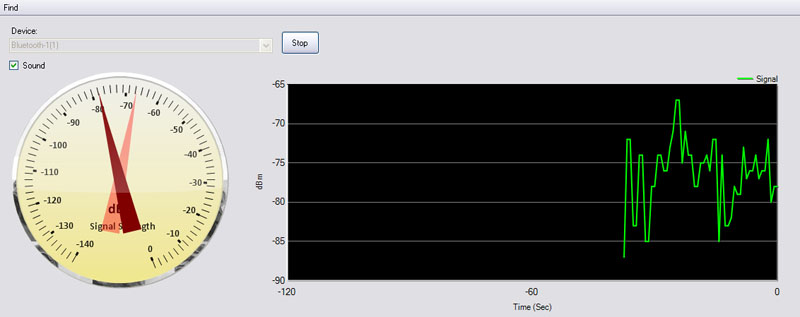
Directional antennas can also be helpful coupled with a spectrum analyzer. The directional antenna can be used to stand in a single location and point the antenna in different directions to see where signal levels peak. Be aware that in indoor environments the source may be originating from a different floor and that signal reflections and multipath effects are more common.
Specifically, the types of bad interference you should watch for are ones with very high duty cycles. A list of APs that you picked up at about −90 dBm and with duty cycles of less than 10 percent is not something that generally requires immediate attention unless the environment or your customer warrants it.
Interference from intermittent, non-Wi-Fi transmitters can be quite troublesome and frustrating to deal with. Intermittent interferers are often the most difficult to identify and locate. It is comparable to a person experiencing problems with their PC and an IT person is called over to resolve the conflict but the problem does not occur; when the IT person leaves, the problems start to occur again. With RF interference it is worse because unless a spectrum analyzer is used at the time, it is often hard to determine whether it is an equipment problem, a network problem, or an application problem. Trigger features that automatically initiate data gathering come in handy in this situation.
Whenever an RF survey is performed, each microwave should be checked for interference severity. As you’ve read repeatedly in this book, microwave ovens will interfere with Wi-Fi, but some are drastically worse than others. Microwave ovens use a variety of types of shielding to keep the microwave signals used to cook the food from escaping the oven. The fact is that some manufacturers do a far better job than others. What’s more, the shielding can deteriorate over time after repeated use.
When the shielding deteriorates, the microwave needs to be replaced. Fortunately, microwaves are cheap and their cost pales in comparison to the cost involved in troubleshooting incidents related to microwave oven interference. Microwave ovens most certainly fall into the category of intermittent RF interferers.
Suspicious Rogues
Rogue APs come in a variety of forms. Rogues may be neighboring APs that you can’t do anything about, or perhaps they are APs within the same deployment area of your target location that you are surveying. Here are some examples of rogue APs that should be escalated upon discovery:
- An AP connected to the wired LAN with no security
- An AP that is consuming a great deal of channel capacity that is affecting performance
- Non-802.11 network devices, such as frequency hopping (FH) APs
The benefit of using unlicensed frequency bands is that you do not have to purchase a license to operate in that band. Because the band is unlicensed, the sales volume of manufacturers is exponentially higher and therefore the costs are low and fiercely competitive among equipment manufacturers. On the other hand, the problem with unlicensed frequencies is just that—they are unlicensed. Anybody can use the spectrum and there isn’t much you can do about it.
Rogues are considered a fact of life in many environments. However, rogue APs deployed against policy by employees or hackers on your network are nearly always within the purview of the design team. Regardless, it is best to quantify the effects of each rogue AP and locate each one within the coverage area of your network design.
For 802.11a/b/g/n radios, this task can be fairly simple. Performing a passive site survey scanning all available channels using a dual-band 802.11 radio will usually uncover all of them. Assuming the surveyor wasn’t sprinting through areas, a rogue AP should be caught. Survey mapping software often has filtering options that display in a map the signal strengths of each unique AP that was found during the survey, clearly indicating areas of the highest signal strength.
Finding IEEE 802.11 FH devices is more difficult. The reason is that the narrowband spikes of each FH transmission can travel for quite a distance. Here again you’ll want to use a directional antenna to help determine the direction of the device.
It is sometimes possible to find APs that have been hidden by employees providing their own Wi-Fi service. This is most common in areas where Wi-Fi hasn’t already been deployed. Hidden APs are difficult to find. They can be located above drop ceiling tiles or mounted to the bottom of desks. Figure 9.19 shows a heat map of a rogue AP discovered during a passive scan of a facility.
FIGURE 9.19 Heat map of a rogue AP

A list of rogue APs that have signal strengths stronger than −80 dBm should be escalated to your project team or customer immediately. Chapter 15, “Design Troubleshooting,” describes troubleshooting techniques for handling rogue devices.
Mounting Restrictions
One of the challenges of designing WLANs is that you can’t always place an AP or antenna where you need it. Placement limitations are common and although they can be frustrating, they are a reality of the job. This challenge is particularly evident when you’re placing outdoor APs.
You will usually find that there are relatively painless solutions available to overcome outdoor placement limitations, but in some cases the problem affects the design of the WLAN in a particular area. When this is the case, you need to alert the stakeholders of the WLAN. Suppose you have to cover a long, narrow walkway and you cannot place equipment down the middle (due to a variety of reasons). As the tunnel fills up with people, equipment, or other things that affect RF propagation, the signal degrades in the middle of the tunnel to an insufficient level.
Various mounting restrictions include the following:
- You are unable to install an AP or antenna in the most convenient location.
- You are unable to get unshielded twisted pair (UTP) cabling or power into a specific location.
- The WLAN exceeds the cable length limitations.
Ceilings
High ceilings are a common trouble spot for AP placement for two primary reasons. First, it is difficult to install the AP because you might need a man lift. In general, if something is difficult to install, consider the effectiveness of that solution and use locations where access to that placement at a later date will be less burdensome. If you can’t survey in that location, that’s a hint that you might want to reconsider the placement. Second, high ceilings may not provide the best RF coverage to your WLAN clients; the signal may not have enough vertical gain in order to provide sufficient coverage.
Hard and decorative ceilings can also be tricky locations to install APs or antennas. We forget how spoiled we are when using drop ceilings with removable tiles whenever we have to run additional cable. With hard or other types of permanent ceiling construction, installing an AP may be unrealistic. But although hard ceilings are a requirement for some facility locations for a variety of business reasons, in order to maintain a sufficient level of serviceability to the building, access panels are often installed in these rooms, allowing you to pull your cable through.
Even with a drop ceiling with removable tiles, cable runs might not be easily achieved. You never know what is above the ceiling tiles, and you always need to confirm with the proper personnel.
Ceiling challenges aside, there may be areas where running cable presents a formidable challenge for other reasons—too many to mention here. The point is that, ironically, it takes a lot of wire to design and deploy a wireless network.
Proximity Limitations and Obstructions
Proximity restrictions to other hardware or systems can also pose a challenge. These include minimum distance requirements from fire suppression systems like sprinklers, sensors of various types, and other types of RF devices.
Mounting an AP near a sprinkler head that is used in the case of a fire will restrict the spray pattern of the sprinkler. This is just an example, but other systems have proximity restrictions, so you want to check local building codes or a licensed authority.
Co-locating other RF systems immediately adjacent to each other is not a good idea. Examples include some cellular systems (like distributed antenna systems), two-way radio, telemetry, and similar systems. Even though those systems may not be operating on the same RF channel, there are sometimes side effects like intermodulation. Generally speaking, do not mount an AP within 1 meter of another antenna system. The farther away the better you are.
Always consult local, state, or federal regulatory building codes whenever installing an AP. As we’ve mentioned in other parts of this book, a variety of industry vertical regulatory requirements come into play, depending on the type of venue.
Materials that have been commonly used for construction have changed over the years. Most of you may have heard of asbestos, which is an insulation material that was commonly used for a number of years. Asbestos is now banned and considered highly hazardous, and you may face it in a future design. If the building where you are installing looks old, you should ask whether asbestos was used in the building’s construction. If that is the case, it might drastically change the locations available to you for your design. Costs can also greatly increase when you have to run cables in a building that contains asbestos.
If you are installing equipment or cabling indoors, you may have plenum requirements to deal with. A plenum space is an area, usually above a ceiling or below a floor, that is used for air circulation in inhabited areas. The concern over plenum spaces is related to fire. When higher air circulation is available, so is the availability of oxygen that will make a fire grow stronger. Whenever plenum requirements are present, you have to factor in every component of an AP installation—including the cabling, the AP itself (not all APs are plenum rated), and antenna cables.
There are other mounting concerns that may seem like common sense, but it is still quite common to see mistakes made. Be cognizant of mounting locations that affect door openings, roll-up doors, or other facility materials.
When you are faced with mounting APs that have high security access restrictions, determine whether performing maintenance or troubleshooting will be possible. This caveat also applies to certain areas like hospital operating rooms (ORs). ORs have highly erratic schedules and may completely restrict any IT personnel from doing anything with the AP while operations are in progress.
Cable Length Limitations
Copper twisted pair cabling is commonly referred to as UTP, CAT5, CAT6, and so forth. This cabling has length limitations when used with Ethernet networks. The distance is approximately 100 meters, or approximately 328 feet, and PoE requirements follow the same limitation. You need to consider the entire cable length required from the switch port to the AP, which may also include one or more patch cable lengths. The entire length has to be less than 100 meters.
If length is not an issue, it is always best to install service loops at the ends of cable runs. A service loop is excess cable neatly looped at the end of a cable run. The service loop allows you to move the cable if you have to relocate an AP in the future.
When cable runs get too long, it usually gets expensive. Fiber-optic cabling is usually the only way to run cable from one central place without adding another Ethernet switch. If there are a lot of runs that will be over the 100 meter limitation, it might be best to install another PoE switch. You can then place the switch in a location central to all the cable runs and run a fiber-optic line to it.
Not everyone realizes that it is possible to order pre-terminated fiber-optic cables to different kinds of lengths. This also may be the cheapest, fastest, and simplest option in some cases. Fiber-optic cable has a reputation for being expensive because of the equipment and specialized labor required to terminate the cable, but fiber-optic cable is the most cost-effective and efficient option for some environments.
If you do not install a new Ethernet switch and are planning on running fiber-optic cable to the AP locations, you will likely have to factor in two things: powering the AP via a nearby electrical receptacle and having to convert the fiber-optic line back to UTP. Often running a new electrical circuit in itself can be a costly situation and also adds points of failure to the equation.
The important point is that you will need to factor in all these costs and design considerations. The best advice we can give you is to present all the options to your customer and let them decide. Some customers may prefer the more expensive alternatives based on other projects or situations they have been working around.
Asbestos also comes into play again when considering cable length limitations. It may be logical to run cable around an area where an AP needs to be installed, thereby requiring more length of cable to place an AP where you want it. All aspects of cabling need to be considered.
Changes to Coverage Area
Part of the challenge of planning surveys is dealing with out-of-date maps of WLAN coverage areas. It is important to ensure that you are dealing with accurate maps. CAD drawings and maps are one of the most critical components in a WLAN design planning effort. If they are not accurate, change orders may be necessary, resulting in extra cost and perhaps time overruns.
CAD drawing accuracy is important for your survey because if you are performing an active survey and walking through an area, you are basing your map location on the current physical location while constantly comparing your real environment to the CAD drawing. When you click on the map, a data measurement is recorded at that position. If the map is not accurate, from the perspective of the CAD drawing it might appear that you are walking through walls or, worst yet, the representation of your data will be inaccurate.
When you encounter this situation, the worst thing you can do is pick spots on the map that aren’t to scale with the rest of your data points. Survey mapping software relies on distance calculations in addition to measured data, and if your data points are not accurate in 2D space, the survey results will not be accurate.
If it is possible, attempt to click on the map based on the location where you think you are standing relative to the map you are dealing with. Doing so can provide some data to analyze at a later date even if the map isn’t accurate. The main risk involved in this process is human error in recording data points at the actual locations.
Predictive surveys will be inaccurate when CAD drawings are out-of-date. If walls and rooms with large furniture are installed where the drawing shows open space, the prediction will be useless.
When you find yourself in this situation, you must escalate the problem to the project manager immediately. Sometimes it may be so minor that it doesn’t affect the design, but in other situations it might drastically change the schedule and costs.
Notifying Personnel
During the course of your work, employees will stop you for various reasons. Some are simply inquisitive whereas others are disruptive. For example, if you are performing a survey or spectrum analysis and enter an area where employees are present, they may not have been told that visitors would be performing work. Reactions will vary, but be prepared in case someone has a negative reaction.
Some people simply react a certain way because management or business policy requires them to do so. This is why the proper preplanning steps must be taken in order to ensure local procedures are followed and policies are being adhered to. A good rule of thumb is to request a company escort so they can explain your presence to anyone who hasn’t been notified.
Another option is to use the presurvey walkthrough to identify locations where employees may not know of your presence. Because this walkthrough is almost always done with an escort, it is also a good opportunity to introduce yourself to local management and security personnel.
Obviously, a security badge or other identifying information is an excellent safeguard that can also prevent uncomfortable situations.
The Spies Are Among Us
When performing a site survey in a large enterprise facility, this author was stopped by an employee who was greatly concerned about what was going on. Picture me standing there with a tripod with a bunch of antennas, electronic devices, a power supply, and laptop computers. A local employee who noticed me was convinced that management had sent me in to spy on their department and that we were planning to install surveillance equipment. The employee caused quite a ruckus.
Unbeknownst to me, there had been a tenuous situation only a few days back between management and the local department that resulted in some friction. My project was delayed several hours by the time management was called in and we demonstrated the equipment and project details.
Designing a WLAN to support both 2.4 GHz and 5 GHz from the same AP infrastructure can be quite a challenge considering the two frequencies propagate differently. Also, APs and clients can behave or perform differently at different bands and even channels within the band. This calls for extra attention to the type and configuration of survey equipment being used.
Antennas are one of the biggest areas of concern. In Figure 9.20 you see an indoor AP with an omnidirectional antenna pattern for 2.4 GHz and 5 GHz. This AP clearly has a different propagation pattern between 2.4 GHz and 5 GHz. Some external antennas to dual-band APs also exhibit these characteristics. You must be careful about your antenna and other design choices that exhibit these types of characteristics if your design calls for dual-spectrum deployments.
FIGURE 9.20 Enterprise AP azimuth pattern

As you can see, if your antenna pattern is different, there is nothing you can do about gaps (or overlaps) in signal. In this case, you should seriously reconsider your options.
For APs with internal antennas, it is uncommon to see this kind of irregular pattern between bands. Equipment manufacturers are getting more experience every day making products with internal antennas and the antenna designs are improving with this collective experience. Large variations in antenna performance seem to be fewer nowadays, making our job as designers even easier.
If you take the time to look at antenna patterns between different manufacturers’ products (or even products from a single manufacturer), you will see a great deal of variability in antenna and radio performance. This is why you should survey using the vendor’s equipment that you intend on deploying. Changes to antenna types and orientation will render a survey null and void.
You must also determine transmit power differences both within a single band, but also across any other bands the device operates at. Regulatory domains play one of the biggest roles in this equation. A radio that’s capable of higher transmit power may limit output because you have configured the AP in a regulatory domain where transmit power in all or part of a frequency band is required.
The 5 GHz UNII bands used in the United States and other regulatory domains fall into this category. According to FCC part 15.407, UNII-1 (5.15–5.25 GHz) transmitters should not exceed 50 mW (17 dBm) EIRP. There are cases that are outside the scope of this section that can reduce EIRP to 40 mW (16 dBm). For example, assuming 50 mW max with a 6 dBi antenna, the transmitter output cannot exceed 12.5 mW (11 dBm).
Granted, a single dBm difference isn’t going to make the spectrum police knock on your door, but the difference is when an AP is designed with internal antennas. Because the antennas are fixed, the AP will be designed to operate safely within this spec, so you might even expect this to be the lesser value.
Understanding Client Support
Whenever you plan to operate at two bands simultaneously, pay close attention to your client device configurations. You must also include capabilities in your assessment.
Most older 802.11a adapters will not operate in the UNII-2 extended (2e) band that was opened up for use after they were manufactured. The same goes for infrastructure devices. You can’t blame the equipment vendor of the devices; it is a fact that technology changes, and in this case, there was a change in the fundamental factors that equipment manufacturers designed to.
Intel’s 3945 and earlier adapters, for example, were based on regulatory and certification requirements at the time. Therefore, when the FCC later opened up additional frequencies at 5 GHz, the Intel devices were not certified to operate in that space. Keep in mind that manufacturers have to get their devices tested by independent testing laboratories. The tests at that time didn’t address those frequencies and therefore the manufacturer had to recertify those devices with the FCC—which proved to be a costly expense (assuming a device was even capable of the new frequency operation). We aren’t picking on Intel in this case; all 802.11a devices certified in that era fall into the same category.
It’s likely the adapter can operate at those frequencies, but it is not certified to do so. Therefore, it would be a legal concern should a new firmware package be available to enable its use.
Why is this important? Think about the scenario of deploying a new infrastructure product that is capable of operating at UNII-2e. If you have a legacy client that doesn’t support UNII-2e and it roams to an area where the AP is configured for a UNII-2e channel, guess what would happen. The client would be disconnected from the network if it didn’t drop down to 2.4 GHz operation. Effectively, the service area provided by that AP operating at UNII-2e would be a black hole to those older client devices.
If you have older client devices that you must support at 5 GHz, you unfortunately need to disable UNII-2e channels in order to avoid disruption to those client devices.
Utilizing Dual-Band Antennas
Another area that has gained a lot of attention for designers is dual-band antennas. These antennas primarily come in two forms.
Single Antenna The first is a single antenna with a single antenna connector that is tuned for both frequencies. This type of antenna is most appropriate for radios that can be software configured to operate in multiple bands.
Single Antenna Enclosure Housing Multiple Antennas The second type, as shown in Figure 9.21, is a single antenna enclosure that houses multiple antennas dedicated to different frequencies using different antenna connectors. In this case, the antenna connectors are marked to indicate which antenna connector goes to which radio.

In the first scenario, where a single antenna element is used for multiple bands, you usually have to sacrifice some performance. Antennas are optimized for specific frequencies or frequency ranges. When you have multiple channels and frequencies you have to support, it is usually the case that some channels do not perform the same as others.
This would cause an inconsistent performance of the AP based on what channel the AP is currently set to. Assuming the antenna has been designed sufficiently, the penalty might not be that noticeable.
Consider for a moment how client device antennas are designed. Specifically speaking, we are talking about the dual band–capable clients. The same problem exists for the antennas used in these devices. If performance on a particular channel is deficient at the AP but slightly better on that channel at the client device, the impact will be less perceived. The problem is when both sides have deficiencies on that same channel. In such cases, you may very well notice that your signal coverage is not as good on one channel as it is on another.
This is not a common scenario, but it is important to point out the most fundamental aspects that affect WLAN performance. When troubleshooting, thinking all the way down to the physical layer is very important.
When choosing a WLAN client to survey with, it is important to consider the target client population. As we’ve stated elsewhere in this book, you do not want to pick a high-performing WLAN client to perform your surveys because the data will not be consistent with your lower-performing devices.
The following is a minimal list of criteria that you should consider when selecting a survey client:
Diversity Diversity helps mitigate the negative effects from multipath. Diversity will even out signal strength hysteresis of reported measurements. Not using diversity in your survey client will result in more irregularity in the RF signals it reports, and you may experience more retransmissions and cyclic redundancy check (CRC) errors. This issue may or may not reflect your client conditions.
MIMO The use of MIMO in a survey client is another worthwhile consideration. Specifically, a MIMO client will exhibit signal processing improvements as compared with an 802.11a/b/g client. Again, the important factor here is to match the survey client with the lowest common denominator of your intended client population. MIMO is an excellent technology for 802.11 performance enhancements, but the improvements may not reflect the expected behavior of your actual client population. If MIMO is in use by your clients, choose an adapter that supports the MIMO configuration (number of transmit and receive radio chains) and 802.11n features that are present in your client devices.
Polarity Polarity enters into the equation when you’re performing outdoor installations or you are operating a client device at a farther distance from an AP than with typical indoor situations. In outdoor or very large, open indoor environments, use higher-gain antennas that allow clients to connect from farther distances. The polarity of the RF signal has a greater effect in these situations. That means that when performing a survey in these situations, consider your client population and mimic the real-world conditions.
Frequency and Band Support Remember that not all clients support multiple bands. Some client devices that support these different bands can be configured to not utilize the additional frequency real estate.
Some client devices may even differ in their performance within a single frequency band. There has been more than one defective adapter. You need to test your client device across several different channels and ensure that you have a properly performing adapter across all the survey channels.
Figure 9.22 illustrates an approximate frequency bandwidth comparison between 2.4 GHz and 5 GHz. There is a marked difference in how an antenna manufacturer will design something for 2.4 GHz versus 5 GHz. Using the same antenna for both frequencies is yet another challenge. Not all channels will perform equally across multiple bands. This will affect the channels that you use to perform your site survey.
FIGURE 9.22 Relative frequency bandwidth comparison
Another important point to remember is the survey client settings. You must prepare your survey client to ensure that device behavior is what you want to observe. Pay specific attention to transmit power settings, roaming thresholds, and channel bonding.
Frequency Band–Specific Considerations
We have already discussed a great deal of detail related to frequency bands and considerations when performing a survey. For reference, here are a few details that need to be discussed:
- Transmit power and modulation type
- Regulatory channel and transmit power restrictions
- Band support
- 20/40 MHz channels
- Benefits and challenges of more channels
Transmit power and modulation type are pretty straightforward topics and have been discussed elsewhere in this text. In short, transmit power usually is not equal across frequency bands and even more so across modulation and coding types. For example, DSSS and OFDM usually do not have the same maximum transmit power for many APs and nearly all client devices. Also, as PHY rate increases, transmit power also backs off for various technical constraints.
Regulatory domains will further limit transmit power and even operational modes in different bands. Different regulatory domains also limit the bands that are available for use.
Spectrum band support includes not only the 2.4 GHz ISM and 5 GHz UNII bands but also the 4.9 GHz band. This is especially true for outdoor operation for municipal customers. Even within 5 GHz, the UNII-2e band was added after many client devices were sold. While operation in the UNII-2e and the 4.9 GHz bands will add some complexity to the survey, the process isn’t any different than designing for 2.4 GHz and 5 GHz. The same steps must be followed.
Channel bonding as used with 802.11n is also not consistent across all hardware. Even though 802.11n supports channel bonding at both 5 GHz and 2.4 GHz, it is not recommended to support channel bonding at 2.4 GHz.
Even though it might be possible to configure 40 MHz channels at 2.4 GHz on an infrastructure product, you will find that many client devices do not support 40 MHz mode at 2.4 GHz. In fact, the 802.11n standard built in a feature to advertise “intolerance” for 40 MHz operation to the infrastructure, as described in IEEE 802.11n-2009.
Having more channels is a double-edged sword. The more channels an infrastructure operates at, the more channels a client device will need to scan when roaming. If voice is used at 5 GHz, for example, its quality may be affected whenever the handset has to roam. Unfortunately, no Information Element (IE) with beacons and probe responses advertises the list that the collective infrastructure operates at.
When designing a new WLAN, you must determine the applications that will need to be supported. For example, if voice is a target application, supported PHY rates in most enterprise deployments should not include the lower DSSS rates such as 1, 2, and 5.5 Mbps.
Whether these rates should be supported or strictly disabled is a contentious topic. Every voice vendor uses different techniques and differs at least slightly in their design recommendations. Regardless of which side of the fence you sit on, the most benefit is gained by making a higher data rate a basic rate. As you may recall from Chapter 3, “Designing for Applications,” where we discussed voice and real-time applications in depth, the lowest basic rate is the PHY rate at which an AP sends all its management frames. Making 11 Mbps the lowest basic rate means that 11 Mbps will be the PHY rate at which beacons and other management frames will be transmitted.
Having to support applications that require higher PHY rates means that you must design the network to support RF conditions to ensure the lower data rates will not be needed. Outside of the basic rate factors, lower rates are needed only when RF conditions warrant their use—when RF signal quality is at its worst.
When you design a network with those PHY rates disabled, make sure cell edges have a sufficiently high SNR to make higher dates possible. For example, voice deployments use a value effectively equating 25 dB of SNR, which will ensure enough RF signal quality to support very high PHY rates.
If you are designing a network that will have minimal usage, such as for handheld computers that only use Telnet or similar types of low-bandwidth applications, you can use fewer APs and support lower PHY rates to enable connectivity at longer distances.
Lower PHY rates travel much farther distances than higher PHY rates . . . well, actually, they travel the same distances but their modulation is simple enough that their signals can be decoded from much farther away. Using lower PHY rates also means more contention to the medium because they travel much farther and likely will cross over into nearby same-channel APs. That means channel 1 clients and APs using lower PHY rates will affect other channel 1 APs in relatively close proximity.
The other problem with lower PHY rates is that your applications will be bandwidth restricted. If higher PHY rates are supported and used for the vast majority of the traffic, bandwidth would not be a problem. However, even a single client device at a cell edge sending a large amount of data would be doing so using a low PHY rate. That would result in very high channel utilization, penalizing other users of that same channel within earshot of the transmissions.
Once you have factored in your client devices and applications, you need to decide whether you will be designing your WLAN for high PHY rates and thus installing a higher number of APs, or designing for range and thus trying to maximize the coverage of each AP.
Designing for Rates
Designing for rates means that you are trying to design for higher PHY rates. Higher PHY rates require high signal strength in order to support the higher modulation and coding schemes. The closer you are to the AP, the better the signal quality is, assuming that transmit power is balanced on both sides of a link. This usually requires that you place APs closer together.
When APs are spaced closer together, you have to deal with the negative side effects of co-channel interference. Figure 9.23 depicts a highly simplified AP deployment using three different channels. Keep in mind that this type of simple RF propagation plan never exists in real life and is used for illustrative purposes only.
FIGURE 9.23 Three-channel design

When designing for high PHY rates with densely located APs it is important to also reduce transmit power to avoid co-channel interference. It is often mistakenly thought that simply disabling lower rates will suffice to prevent interference and excess contention to neighboring cells. In reality, the AP’s transmissions at higher rates will still travel the same distance, but the usable range of those transmissions will be shorter. The RF amplitude of those signals will not change as a result of supported data rates. Even so, it is important to disable the lower rates in this design scenario so that clients can only connect within the intended high rate area, and not at great distances from the AP, which could add contention problems for neighboring cells.
Lower data rates also require more time to transmit the same amount of information. When any device transmits using lower PHY rates, it penalizes the other stations also operating nearby on the same channel by bringing down the total amount of throughput the medium would normally allow. That means that other higher-speed devices will have to wait until the slower-speed transmission is finished. Potentially, if other higher-speed devices were to use the wireless medium at the same time, the total amount of throughput the AP would be able to sustain would be far greater.
When designing for rates, you must strongly consider the negative effects of co-channel interference when using the lower data rates.
Hospital VoWiFi Deployment Gone Bad
A large hospital purchased a VoWiFi solution and deployed its Wi-Fi network based on the vendor’s best practices. APs were spaced quite closely, and the hospital was told that automated RF management would resolve all the RF configuration and tuning. The entire infrastructure was installed and turned on, and the network sat overnight in order for the automatic RF management algorithm to fully tune the large, multifloor hospital facility.
The phones were configured and deployed to the staff, but the phone performance was very poor. IT staff from the hospital worked for many days performing tests and checking signal strength in order to figure out what was happening.
Finally, the hospital IT department resorted to bringing in a consultant and demanded that the person be a Certified Wireless Network Expert (CWNE). The consultant arrived at the hospital and after interviewing the staff they went to visit an area of the hospital where the phones were deployed.
The CWNE noticed that APs were spaced very closely to one another and that they all were placed in the hallways. The consultant used a Wi-Fi analyzer to measure the VoWiFi phone conversation and noticed that RF channel utilization was at about 50 percent of capacity. Worse yet, the VoWiFi phone hadn’t even dialed and nobody else was using the network.
Immediately the CWNE noticed that all the data rates that were occupying the channel were at 1 Mbps. Each AP was serving six SSIDs for various purposes. The CWNE then noticed that all the 1 Mbps transmissions were beacons from the APs. The number of APs that were seen from a single location totaled over 100.
The problem was that with a highly dense deployment, six SSIDs, multiple floors, and 1 Mbps enabled, 1 Mbps transmissions can be heard from very far away. The CWNE informed the IT department that disabling 1, 2, and 5.5 Mbps would not negatively affect client connections because of the density of the AP deployment throughout the coverage area. After reviewing all the facts, the IT staff disabled two of the SSIDs that weren’t being used at the time and turned off the 1, 2, and 5.5 Mbps data rates. The channel utilization went down to 6 percent.
Once that was done, the performance of the wireless network skyrocketed and phone operation met the original expectations.
Designing for Range
When you design for range, you are making a conscious decision to leverage lower data rates and seeking to maintain client connections at maximum distance. This method is commonly used for outdoor environments and sometimes for warehouse environments.
By choosing to design for range, you are also consciously giving up WLAN capacity. Capacity, in this situation, can be considered in speed and number of clients. When using lower data rates, the same packets that need to be transmitted over the wireless medium simply take longer. That means the rate at which the transmissions are sent is lower. Therefore, the effective throughput of the WLAN is decreased.
The other area of capacity relates to the number of client devices. When lower data rates are supported, assuming the same types of applications are being run on each client, each client produces additional load on the wireless medium. Assuming that each client device behaves in a similar way, each client represents a finite amount of contributed traffic to the overall workload on the WLAN. This means that fewer wireless transmission opportunities exist and therefore the number of wireless clients is decreased. The amount of traffic in a wireless medium is inversely proportional to the number of new client devices that the WLAN will support.
Not all Wi-Fi network deployments are Greenfield. Nowadays, chances are a Wi-Fi network already exists and the design needs to be upgraded. Sometimes only a few APs might be deployed. Or perhaps the entire network needs to be augmented, analyzed, or even replaced with an 802.11n network.
Performing work on an existing WLAN can present some unique challenges in comparison to designing a new network from the ground up. Active surveys, for example, can be more difficult if the only SSIDs are 802.1X/EAP enabled. The existing network might also incorporate automatic RF management and transmit power might be highly variable on an AP-to-AP basis. Finally, some companies take issue with survey APs using the same channels during hours of normal operation.
Technology Upgrade
One of the most common reasons for updating an existing design is that the equipment is getting old and is no longer supported. Another reason is that the business is relying on the WLAN more heavily than ever before and requires a technology upgrade to support higher speeds, more spectrum, or specific features.
When technology changes, the existing AP layout may not provide a baseline for the new technology. One example involved the earlier 802.11 FH systems. FH APs could travel quite some distance, but the speeds were limited. Warehouse environments in particular were heavy users of FH technology and found themselves adding a much higher number of DSSS- or OFDM-based APs when replacing the older FH-style APs. Therefore, you may not be able to leverage the existing Ethernet cable runs and mounting locations. Be sure to inform your customers if that’s the case.
Customers found themselves in a similar predicament when upgrading from 802.11b AP technology using 2.4 GHz only to 802.11a/g-based APs using dual spectrums. Designers found that usable 802.11a cell sizes were often smaller than the previous 802.11b cell sizes, and they needed to factor in more APs and tighter spacing.
Technology will continue to evolve. In fact, the IEEE is working on a gigabit PHY technology under two different standards called 802.11ac and 802.11ad. It’s premature to discuss the details of those standards, but when this technology arrives there will yet again be more design challenges involved in technology upgrades. In the meantime, it is best to focus our efforts on 802.11n and associated design strategies.
It took many years for 802.11n to arrive as a fully ratified standard. Business and consumers were eagerly anticipating the benefits of better radio technology along with an increase in transfer speeds. Now that 802.11n is fully ratified and every equipment manufacturer has an offering, WLAN designers are finding that many of their efforts are centered on moving from 802.11a/g technology to 802.11n.
Several things changed with 802.11n from a design perspective. These include the following:
Multiple Antenna Elements Using multiple antenna elements is an important improvement in order to gain most of the advantages of MIMO and throughput speeds.
Heavy Focus on 5 GHz The primary benefits of 802.11n rest in the 5 GHz UNII bands, so most designs are now primarily focused on 5 GHz.
Cell Sizes Cell sizes aren’t necessarily a 1:1 ratio to existing 802.11a/g designs. And for a variety of contributing factors, external and directional antennas tend to be less common.
Nobody likes the expense and labor involved in performing site surveys, and several manufacturers have claimed that you can perform a 1:1 swap of existing 802.11a/g APs with 802.11n APs. Then, in a different white paper or marketing bulletin, they may claim a 20–30 percent increase in range. Which is true? Should you simply take an existing 802.11a/g design and swap the APs with 802.11n models?
Before you begin, critique the existing design and understand how it was designed. This process includes interviewing users on how well the existing network has been performing for them. Here are some questions you should ask:
- Is the existing network too dense to begin with? Is the AP placement too sparse?
- Are all the required coverage areas for the new design covered in the previous?
- Was the existing network designed using directional antennas?
A good technique is to experiment a bit. Using a good survey mapping software package (or using other, manual methods), perform a survey of an installed AP. Is the transmit power reasonable? If not, set the transmit power of your test AP to the proper level before performing the survey. Once that is done, place an 802.11n AP in the same location and perform a survey using that AP. If they are roughly equivalent, that is a good start.
Next, perform a passive survey of the entire coverage area. Before performing the survey, consider these important factors:
The Survey Client Is the performance of the existing client devices similar to the devices that you plan to deploy in the upgraded network? If it isn’t representative, then you should use the lowest common denominator of device that will be around for the foreseeable future.
Transmit Power of the Existing APs Because a passive survey is a downlink-only measurement, it is critical to normalize power across the entire environment. Ensure the transmit power is known and ideally consistent across the entire network.
Optimized Channel Scanning Whenever analyzing an existing network using known channels, you should configure your survey client utility to scan only those channels. This gives you more information regarding the channels that you are operating on and provides you with a better basis for analysis.
One of the benefits of a passive survey is that it can be performed quickly. Once that process is finished, take a look at the survey data and review the results. Are there coverage gaps in the existing design? If so, the new design may need to incorporate more APs than the current one has. However, if the existing network is already too dense, you might need fewer APs.
Another factor that is important to analyze in an existing design is AP placement. You have already seen how AP placement affects location accuracy if RTLS will be used. Different placement might be recommended in some areas regardless of whether RTLS is used.
Existing designs might also have all the APs down the center of long hallways and not into the rooms where users are located. Depending on the facility, the APs in the hallways usually hear one another loudly, which usually causes channel contention. At the same time, if automated RF management algorithms are used, this might cause the APs to automatically power down their transmit power to a point where the users in the rooms have limited or poor connectivity. In situations like these, some might argue that the original design was flawed.
Phased Upgrades
Sometimes it can be difficult to update a large WLAN deployment in one single event. In such cases, from a business perspective it might be best to phase in the upgrades.
Phasing in upgrades sometimes has its own unique challenges. Upgrading from one technology to another might not seem disruptive to client applications, but sometimes it is. For example, an existing design might use a specific VLAN for all users and the new design uses another. If the same SSID is used for the old and new infrastructure and they will be adjacent to each other, a client device will roam between the two without knowing that it will be placed on a different VLAN. This will likely cause disruption in user applications.
Another example is when fast secure roaming is enabled, but not functional between the old and new environments. Even if the two WLANs are on the same VLAN, roaming between the two environments might require clients to perform a full 802.1X/EAP authentication on every roam between each other. Remember, the client device seeks any AP that matches its configuration profile for SSIDs. If another AP is a suitable match and the RF signal is better, the device will roam there.
Perhaps 802.11 technology is changing from 802.11g to 802.11n at 5 GHz. Does the client driver and AP firmware allow state to be flipped back and forth seamlessly between the two technologies? Bugs may be revealed when moving between the two in one or both environments.
Phased upgrades are best performed in geographically segregated areas, perhaps one building at a time. One floor at a time in a multifloor building is not the same thing—clients often jump between APs on different floors in most multifloor AP deployments.
Upgrading Clients
When upgrading an existing design, take another hard look at the client devices. When mobile carriers upgrade their networks, phones often need to be upgraded as well. Many of you know from experience the benefits of updating your mobile phone at times.
WLAN client devices are no different. When a newer AP technology is deployed, client devices will have to be programmed to take advantage of new features. Perhaps the driver is old and would benefit from an upgrade anyway.
The point here is that whenever you upgrade your WLAN infrastructure, you must perform some level of upgrade, or at minimum, some level of monitoring, to your client devices. Even if that involves a simple driver update, this step usually provides results with a high payback.
After performing a site survey, you have a lot of data to look at and make sense of. It may feel like a daunting task reviewing all the information in detail.
One of the first things that you should do when reviewing survey data is to look for common problems that surveyors make. Performing an 802.11 RF survey isn’t exactly a science that has been around for a long time. And not everybody gets to attend expensive training programs.
A nice side effect of reviewing site survey data is that you can often filter on rogue APs. Looking for interference issues is also important when viewing survey results.
In this section we will explore the common problems with interpreting survey results and looking for key findings from the data gathered in the coverage area.
Common Problems to Look For
Let’s assume that you are looking at a site survey that was performed by a third party. The survey file says that it was a passive survey. You learned several attributes of passive surveys earlier in this chapter, so you know that when performing a passive survey a WLAN client doesn’t associate to the AP. The benefit of this approach is that you can see richer data about all the APs in an environment. The problem is that the survey client constantly scans a preconfigured set of RF channels.
Configuring these channels appropriately for the type of analysis that needs to be performed is critical to providing the type of data required. For example, assume the survey client was configured to scan all 2.4 GHz channels and the network being surveyed was an SCA using only channel 6. In this case, the client constantly scans all the other channels using a dwell time of 250 ms. That would mean that scanning 2.4 GHz channels 1–14 would take 3.5 seconds to complete. If the surveyor was walking at a brisk pace, the data resolution may not be as fine as desired because channel 6 data samples were not frequent enough.
When reviewing survey information, try to interpret the information being presented to ensure the scan settings were properly configured for the statement of work required.
Another common problem is erroneously reporting interference. The interference in this scenario is what the interference analysis modules of survey mapping software programs report. Suppose you are analyzing an existing WLAN deployment and device to use a passive survey to perform a downlink coverage assessment of the WLAN. When you review the results of the survey using the survey mapping software package, it provides an interference analysis report. If the network being surveyed was running multiple SSIDs, it is highly likely that the survey mapping software would see each SSID from each AP as individual APs. When multiple SSIDs are used, a different BSSID (MAC address) is used on the AP. When this is the case, the survey mapping software sees a unique BSSID and assumes that it is a stand-alone AP. Therefore, the survey mapping software interprets this as multiple APs deployed in the same spot using the same channel. You will need to filter the data from the passive survey so that the interference analysis report includes only a single BSSID from a single AP that was surveyed.
One of the most common problems is improperly scaled maps. When maps are imported into survey mapping software packages, the graphic file is scaled to the screen. Each pixel has no relevance to real-world dimensions because graphic files do not contain this information about dimensions. Survey files might be skewed in one dimension more than another when they are first imported. You can usually tell this by looking at text and doorways between the x and y dimensions. Doorways of similar type are usually exactly the same. Using that information to your advantage will allow you to quickly determine whether the surveyor scaled the map before performing the survey. Another method is to use a measuring tool in the survey mapping software to measure points on a map and confirm to known, real-world dimensions.
Another common problem is insufficient walking paths. When a surveyor walks a map to analyze RF coverage, they must click locations on the map within the software where they are standing in real time. The tricky part is that they must also click on the map when they change directions (every time) as well as speed (every time). If that step isn’t followed, the survey software package keeps recording data at predetermined intervals and spaces the data points equal distances apart between the two mouse clicks. If a change of direction isn’t recorded and the survey mapping software isn’t stopped, paths might appear to go through walls. When you see walking paths do this, it is a clear indication that the data points do not reflect real-world conditions and that the data is likely unusable. Similarly, the surveyor’s walking path should not be limited to hallways and common areas. It is important that accurate coverage maps be obtained by gathering data samples from as many points on the map as possible (or reasonable, within the constraints of the project). As data samples increase, so does the accuracy of the heat maps.
Locating and Quantifying Rogues
Rogue devices or networks can impact the performance of your network. Rogue devices from company personnel usually can be quickly remedied, but rogue devices from neighbors can’t. Part of the challenge of using unlicensed frequencies is that as long you are staying within the regulatory transmission limits, people are free to utilize that frequency. That means you have little to no recourse to do anything about it.
When performing a site survey you can locate rogue devices quickly, but passive surveys are the best way to locate rogue devices. Most survey mapping software allows you to filter the survey results to show the rogue devices individually, by channel, by SSID, and more. Figure 9.19, earlier in this chapter, is an example of a passive survey that was filtered to show where a rogue device was found during the course of a survey.
When viewing site survey results, always communicate to the proper personnel the survey findings of rogue APs that were discovered during the survey process. In particular, rogue APs that have minimal security policies are ones that require immediate escalation.
Interference Mitigation
Interference from non-802.11 sources is one of the single biggest factors that can wreak havoc on a WLAN. Certainly not all interference is created equal, but by performing a spectrum analysis, you can quantify the impact to the RF spectrum as well as the connection quality (if an active survey was performed). Negative effects from interference include higher retransmission rates while even in an area of strong signal quality, lost 802.11 frames, higher reported noise floor, and connection drops.
Survey results will show symptoms of interference. These symptoms include elevated noise floor, high retransmission rates, and usually lower PHY rates than what would be expected for a given signal strength. You can view the recorded data rom a site survey using several methods. One of these methods includes looking at noise levels across the entire surveyed area. If this area is several floors of a large multistory building, seeing an elevated noise floor is a sign that some form of interference is likely present.
This same information can help you pinpoint where the interference is located. Once a location is loosely determined, taking a spectrum analyzer using a directional antenna can be a helpful method of finding the problem device.
Performing a survey for a single-channel architecture (SCA) versus a multichannel architecture (MCA) theoretically isn’t that different. Sure, you do not worry about the channel settings of the final AP configuration, but you still have to concern yourself with pure RF propagation. Without proper RF propagation, it doesn’t matter what channel one or all of the APs are on.
It seems that SCA vendors more commonly deploy a higher density of APs than do MCA vendors. Because the RF algorithms are intended to be more coordinated between APs in SCA systems, the logic for some is that deploying a higher density of APs with SCA deployments has fewer side effects than with MCA deployments.
While many WLAN professionals debate this topic, APs placed closer together will still have to contend for airtime. When a device transmits on a particular channel, the wireless medium may be occupied. The distance of impact to adjacent devices is one of the biggest differentiating factors. Keep in mind that we are speaking of transmissions from both clients as well as APs.
Simply put, all of the same logic still applies to AP placement regardless of what type of technology you intend to deploy, though the surveying process for an SCA should be slightly simplified because channel and transmit power settings do not need to be carefully managed for contention planning. In SCA networks, transmit power is usually set to max power (usually 100 mW).
One of the most fundamental steps in WLAN design is ensuring proper RF propagation. Without proper RF propagation, the WLAN performance and user experience will be poor. The analogy is equivalent to faulty cabling in wired network design.
In this chapter we reviewed many types of survey methods you can use in order to accomplish a thoughtful and effective RF design. Some are more effective and applicable to certain situations than others. Just as with many things in life, one size doesn’t fit all. It is important that you understand these survey methods and when to best apply them.
Survey mapping software can be a useful asset for performing RF surveys and are a valuable visualization tool for you as the designer as well as the customer of the network. Predictive design software packages are also valuable in some situations, but they can provide inaccurate results if not used properly or if the input and assumptions for the design are not accurate.
Infrastructure links such as PTP and PtMP links have their own unique set of survey requirements and the design techniques are quite different from indoor designs.
When you update existing WLAN designs, you’re interested in leveraging existing assets, but you need to be cautious about utilizing bad elements of existing designs to base a new WLAN design on. Furthermore, when updating the WLAN infrastructure, you should always look to upgrade or update the client devices that will also utilize the new network.
Finally, once all the RF measurements are taken, an analysis process must be performed. You need to be on the lookout for common mistakes people make when analyzing survey output before drawing any specific conclusions.
All in all, RF design is one of the most important factors to a successfully operating WLAN. Without sufficient RF performance, everything that depends on it will be affected. Hopefully this chapter has provided you with a good foundation for improving your future designs.
Explain differences between survey methodologies and when best to apply different ones. Know the differences between active and passive surveys as well as predictive designs, including different modes of each one.
Describe why a spectrum analysis is important in RF design. Be able to explain the major measurement types of spectrum analysis methods and how to interpret results.
Understand the factors involved in designing for multiple spectrums. Explain the various details involved in designing WLANs for more than one spectrum.
Define techniques for designing for rates versus range. Describe details of design techniques for a variety of business requirements that may affect AP placement and high-level design factors.
Understand important factors in updating existing WLAN designs. Understand the important aspects of updating an existing WLAN design and how that will affect client connectivity.
1. Before performing a pre-deployment passive RF survey of a new deployment using survey mapping software, which of the following must be performed?
A. Determining AP transmit power
B. Checking client DTPC settings
C. Scaling the map
D. Selecting antennas
2. When you’re performing a passive survey and channel scan settings are set to all available 802.11 channels, what information will you gain? (Choose all that apply.)
A. SSIDs of all APs
B. Rogue APs
C. AP channel and power settings
D. BSSIDs of known APs
3. Passive surveys performed using only the channels on which an existing WLAN is operating have which of the following benefits?
A. Longer scan times
B. Same as default scan settings
C. More information per channel
D. Less roaming delay
4. You are being consulted to observe a spectrum analyzer recording and you notice strong RF transmissions in narrow spikes across the entire band. What type of measurement have you been shown?
A. Swept spectrograph duty cycle
B. Real-time FFT
C. Return loss S12
D. Max Hold
5. Active surveys benefit from what additional information versus a passive scan? (Choose all that apply.)
A. RSSI
B. Signal to noise
C. PHY rates
D. Retries
E. Loss
6. NicoCo is building a new facility and would like to install a WLAN for primary connectivity of all clients. The requirements are dual-spectrum 802.11n supporting voice and location tracking. What type of pre-deployment survey should be performed?
A. Passive, using optimized channels
B. Active, using a voice handset
C. Active, using a lowest common denominator client
D. Predictive
E. Passive, all channels
7. You are being asked to perform a survey in a multifloor building. The building has very thick walls that you know are going to highly attenuate signal propagation. When performing some analysis onsite you notice fairly strong propagation between floors. What two factors should you be very aware of? (Choose all that apply.)
A. Channel planning
B. Transmit power
C. Hidden node
D. Multi-path
E. Stacking APs
8. Assume Inc. is doing a point-to-point (PTP) network installation and has asked you to be onsite to consult for the alignment and tuning effort. The equipment has been installed and powered, but no link is being made. You can see that the antennas are a short distance away and RF line of sight should not be an issue. What is the first question you should ask?
A. Is your antenna polarization aligned?
B. Did you test configurations before installing?
C. What is the transmit power at each end?
D. What are the channel settings?
9. You are being asked to design a solution for a long-range PTP link using 5.8 GHz. While the distance is well within the link budget, the other end of the links will be difficult to see for alignment. What initial consideration could you factor into your design to ease the alignment process?
A. Additional antenna gain
B. Receive sensitivity adjustment
C. Lower antenna gain
D. Antenna polarization
E. Frequency choice
10. Four buildings are located in a square orientation to each other. Fisch Stix Food Company is requesting a PtMP link between the buildings. On the building with the root bridge link, what type of antenna is the best choice?
A. Vertically polarized omni
B. 60° yagi
C. Parabolic dish
D. 100° sector
E. Horizontally polarized omni
11. You are viewing a site survey report from a vendor who provided spectrum analysis readings. The report show screen shots of the real-time FFT chart where non-802.11 RF interference is seen. When interpreting this data to grasp the impact on the performance of the new WLAN, what can you say?
A. Since other devices are using the medium, it will impact performance.
B. You ask the vendor to include duty cycle before providing any feedback.
C. You ask the vendor to include device classifier information before providing any feedback.
D. Since other devices are present on those channels, you should avoid known bad channels.
12. MUG Inc. has installed a large mesh network in a large convention facility. The mesh APs installed at the farthest end of the building have received a large number of user complaints. What design information should you immediately ask for? (Choose all that apply.)
A. Topology of the network showing root mesh nodes
B. RF signal readings between mesh nodes
C. The number of radios used on mesh nodes
D. The types of applications the network supports
13. Lace Doily Company is highly concerned about aesthetics and you are being asked to keep APs from being visible on the ceiling. What best practice option should you explore as a first step?
A. Install APs with internal antennas above the ceiling.
B. Investigate using small external antennas that can be mounted to the ceiling and walls.
C. Paint the APs or antennas using the same paint used for walls or ceilings.
D. Point out that there are smoke detectors, sprinklers, lighting fixtures, speakers, and other existing items and the APs will hardly be noticed.
14. What factors can prevent mounting APs where your design may call for placement? (Choose all that apply.)
A. Maximum Ethernet cable distance versus maximum PoE distance
B. UTP cable distance
C. Power availability
D. Installation/maintenance labor costs
E. Plenum rating
15. When designing for dual-spectrum AP deployments, what design planning exercise should you perform before starting the full survey?
A. Matching propagation patterns on both bands
B. Normalizing transmit power
C. Telling the customer to use it as an excuse to buy new laptops
D. Infrastructure-based load balancing, which will free up 2.4 GHz
16. Schembs MMA Inc. just installed a brand-new 802.11n network and they have asked your help in determining why legacy clients are having performance problems. You determined the following: 40 MHz channels are in use, all UNII bands are being used, an 802.11n client was used for the survey, 2.4 GHz is not being used, all MCS rates are enabled, and lowest basic rate is 9 Mbps. What items are you most concerned about? (Choose all that apply.)
A. Lowest basic rates
B. No 2.4 GHz is being used
C. MCS rate selection
D. 40 MHz channel settings
E. 802.11n client used for survey
F. All UNII bands are used
17. Sandlin Sandwich Company has asked you to consult on their WLAN upgrade that will be performed in phases. They plan on updating a floor at a time, adding 5 GHz, and would like to change IP subnets. What recommendations do you offer?
A. Change the SSIDs on the new network.
B. Using the same SSID is OK because clients will only connect to the APs on the floor they are located on.
C. Existing client drivers will perform equally.
D. Existing Ethernet uplinks will suffice.
18. You are being asked to design a WLAN for a number of WLAN clients that will use Telnet as the primary application. The customer has asked that you use only the number of APs necessary because of the complex installation and construction costs each AP installation will incur in this particular environment. What design factors do you consider?
A. Use 11 Mbps as the lowest basic rate.
B. Omnidirectional antennas should be used to maximize cell overlap.
C. AP transmit power should be turned down to minimize co-channel interference.
D. Clients could benefit from RTS/CTS mode for all transmissions.
19. Head Thinkers Inc. is asking you to consult on a WLAN upgrade where each AP will be upgraded from a dual-band 802.11a/g version to a dual-band 802.11n AP. When you review the design, what critical factors are you looking for? (Choose all that apply.)
A. Antenna patterns
B. Usage statistics of current network
C. Ethernet uplink speeds
D. 802.11n SGI setting
20. You have been asked to review a predictive design that was performed by a third party. You notice an abnormally high quantity of APs used for a small office building. What might be the root cause?
A. VoWiFi is a design requirement.
B. The network will support a high number of client devices.
C. The design calls for 5 GHz.
D. Map scaling was done improperly.
1. C. Survey mapping software uses FSPL calculations in addition to recorded data. An improperly scaled map will alter the results provided by the software.
2. B, D. When performing a passive survey using all channels, you gain optimal visibility of all APs that can be heard. That includes all known and all unknown APs.
3. C. When you’re performing a passive survey to analyze an existing WLAN, it is best to configure a passive survey client to scan only the channels that the WLAN operates on in order to have more data points for each AP. Channel scan settings set to their default values can spend too much time off channel and create gaps in data that can skew final results.
4. B. The spectrum plot showing signal strength across a frequency range (frequency domain) is called an FFT.
5. C, D, E. Since active surveys associate to an AP, data can be recorded consistent with actual associated stations.
6. D. If the building hasn’t been built, then unfortunately an active or passive survey cannot be performed. However, since the requirements are so great and the WLAN will be used for primary network connectivity and voice, a full active survey should be performed once the facility is built and populated with all furniture and other items that can affect RF characteristics.
7. A, E. Every building and construction method will affect RF propagation differently. It is important to consider three dimensions when planning channels and co-channel interference introduced by stacking APs on top of each other between floors. Staggering, rather than stacking, APs can sometimes provide better long-term coverage at RF cell overlap zones as changes to a facility alter RF coverage patterns, causing weaker overlapping signals at cell edges.
8. B. Installing PTP links require attention to detail in the preparation and testing before actual installation. When on a radio tower or 10+ story rooftop building, all testing needs to be performed prior to installation, such as using multiple power cycles to ensure configuration settings have been properly saved.
9. C. When installing long-range PTP links, antenna gain that’s too high will get you into trouble when you attempt to align the antennas. At least one end of a PTP link should have a lower antenna gain in order to aide in the antenna alignment process. Once proper alignment is achieved during the coarse tuning effort, high-gain antennas can replace the lower-gain antennas after the final pointing direction is determined.
10. D. If all four buildings are in a perfect square orientation to each other, that means they are an angle of 90° apart. Installing a 100° sector antenna on the root node building will provide enough azimuth to reach all three other buildings while rejecting other RF interference in the areas where no buildings are present. Using a sector antenna also minimizes elevation antenna gain (again, where no other building PtMP antennas will be installed).
11. B. Duty cycle will provide the most useful information regarding how existing RF interference will affect a WLAN. You can have very low signal levels but have very high duty cycle, which might hardly register on the FFT plot. Options A and D are cop-outs; 802.11 uses unlicensed frequencies and there will always be some form of interference. Option C may not be possible depending on the spectrum analyzer the vendor used. Worse yet, there may not be classifiers for some forms of interference and, regardless, you can obtain the information you need from the Duty Cycle plot.
12. A, B, C, D. The two top questions should be how many mesh nodes have backhaul connections to the wired network and how many radios are being used in the mesh design. If mesh nodes are several hops away from a root node, it will take several mesh hops before traffic hits the network. This adds latency and congestion from many mesh APs backhauling all their data to a limited number of root mesh nodes. Other factors that will affect performance are signal readings between mesh nodes and the types of applications the network must support.
13. B. Some external antennas are quite small and may still provide good coverage without compromising performance. Installing APs above ceilings will affect signal propagation and is never recommended. Painting APs or antennas must only be done using specific types of paint that will not affect RF propagation. While pointing out existing installed items may seem pertinent, the company likely already knows this and do not want to continue to add to the clutter.
14. B, C, D, E. Ethernet and PoE run off UTP (a.k.a. CAT5 or CAT6) cabling and both have the same maximum usable length (100 meters). If total length between an Ethernet switch and the AP exceeds that length, the AP may not work. Installation and labor costs are a big factor in total WLAN budget planning. Plenum requirements will also limit certain AP and antenna choices if all components are required to be plenum.
15. A. When planning a dual-spectrum WLAN design, one of the hardest parts is having consistent performance between 2.4 GHz and 5 GHz propagation patterns. Transmit power adjustments should be made to optimize propagation patterns while not exceeding link budget transmit power. Spectrum load balancing features may not perform as expected if clients are not capable or not configured to use both bands.
16. E, F. If clients are connecting at all, it means that all legacy clients are 802.11a capable since 9 Mbps is enabled as a basic rate, so that would not be an area you focus on first. MCS rate selection only affects 802.11n clients. 40 MHz channel operation still provides full connectivity for legacy clients using the primary channel. The fact that an 802.11n client was used for the survey is an indicator that legacy clients might not be able to match the same performance and the network might be inadequate for some legacy clients. Since all UNII bands are used, which includes UNII-2e, it is highly possible that some legacy clients do not support UNII-2e channels and the network would have dead spots from the perspective of those clients.
17. A. The most correct answer is A. Since IP subnets will be changed, you do not want clients changing subnets when they roam to APs on different floors, which is likely to happen. Client drivers should not be assumed to perform equally and an upgrade should be investigated. Ethernet links might want to be upgraded to gigabit if 802.11n is being used.
18. D. None of the available options were that compelling, but out of the list, RTS/CTS mode can provide some benefits from hidden node interference if a large coverage area is provided by each AP. Since bandwidth is not a concern, this option can cut down on collisions.
This scenario is a typical rates versus range design situation where you have to design a WLAN to support a particular application and you have design and budget constraints that must be considered. In this case, Telnet is the WLAN application that will be used, which requires very little actual throughput to operate. Therefore, speed of the WLAN is not a requirement, but budgetary constraints are the biggest consideration. Basic rates and other data rates lower than 11 Mbps should be enabled because range is your highest design requirement. AP transmit power has little to do with co-channel interference in this particular design scenario.
19. A, C. Changing out a legacy AP type with an 802.11n AP cannot be assumed to provide equal coverage. Existing APs might use external antennas that are directional in nature. Unless the new APs provide a similar coverage pattern, coverage holes may exist. Uplink speeds are another area for which you might recommend a new 802.11n network.
20. D. One of the most common mistakes people use when performing site surveys is not properly scaling maps. Unless the map is scaled properly, the predictive design software will not be able to determine AP placement adequately.