9
Brain–Computer Interface-Assisted Automated Wheelchair Control Management–Cerebro: A BCI Application
Sudhendra Kambhamettu1, Meenalosini Vimal Cruz2, Anitha S.1, Sibi Chakkaravarthy S.1* and K. Nandeesh Kumar1
1Center of Excellance, Artificial Intelligence and Robotics (AIR) and School of Computer Science and Engineering, VIT-AP University, Andhra Pradesh, India
2Georgia Southern University, Georgia, United States
Abstract
Technology today serves millions of people suffering from mobility impairments across the globe in numerous ways. Although advancements in medicine and healthcare systems improve the life expectancy of the general population, sophisticated engineering techniques and computing processes have long facilitated the patient in the recovery process. People struggling with mobility impairments and especially spine injuries which also leads to loss of speech, often have a narrow group of devices to aid them move from place-to-place and they are often limited to just movement functionality. BCI (Brain Computer Interface) powered wheelchairs leverage the power of the brain, i.e. translating the thoughts/neural activity into real-world movement providing automated motion without any third party intervention. Many BCI powered wheelchairs in the market are cumbersome to operate and provide only singular functionality of movement. To address this problem and improve the state of BCI products, Cerebro introduces the first ever go-to market product utilizing Artificial Intelligence to facilitate mobility features with built-in speech functionality via blink detection. Further sections of the Chapter take an in-depth look into each layer of the Cerebro system.
Keywords: BCI, cerebro, motor imagery, EEG, deep learning, artifact, support vector machine, Raspberry Pi3
9.1 Introduction
According to the WHO disability report, 15% of the world’s population is living with some sort of disability, about 2–4% of them experience significant difficulties in functioning. Also, every year about 250,000–500,000 people suffer a spinal cord injury (SCI) which leads to mobility impairment in these patients. Although their brain activity is intact, their fundamental functional abilities like walking, running and also in serious cases, talking are debilitated. While the cause for these injuries could be prevented, the ones suffering need a viable product in order to help them communicate better and avail spatial movement.
There have been numerous attempts at developing a non-invasive style BCI controlled wheelchair in the past decade itself. BCI presents itself as an interesting application, when the discussion is on products/concepts to aid the disabled, thanks to the rigid structure of human anatomy keeping the brain from most of the damage. Brain is one of the most integral parts of the human anatomy as it is the source of all control, behavior, thought and movement. Neural pathways are wide spread to reach every organ and every part of the body tallying up to, about 7 trillion nerves in an average human body.
The primal mode of communication through the neural pathways are the brain signals originated from the brain, which are triggered upon the intent for a specific action. These brain signals are small electrical impulses which can be detected by the right equipment. After further processing of these signals, they can be converted into readable and control transferable signals which can then be mapped to enable external actions i.e. motor movements, key-taps, playing a sound etc. Several brainwave reading strategies such as SSVEP, EEG – Motor Imagery, etc., which we will be discussing further in the chapter, were implemented to achieve the control of the wheelchair from imagination of the perceived movement. For example, this study by Doron Friedman et al. in 2007 explores the possibility of BCI based wheelchair control for a tetraplegic in a VR environment via translation of imagined motion of paralyzed legs [4].
Another study in 2013, developed a hybrid BCI system combining P300 and steady-state visual evoked potential (SSVEP) strategy for a wheelchair offering control via flickering buttons set on a graphical user interface [5]. The conventional methods and design of a BCI controlled wheelchair is standard and addresses just the mobility issue. However a novel device, Cerebro is introduced which takes it a step further by offering two distinct modes of control and communication. One for the spatial mobility of the wheelchair through imagined motion by classifying Motor Imagery using Deep Learning methods and the other, availing faculties for patients with speech impediments, offering text to speech control via BCI. In depth look into these systems will be followed further in the chapter (In the Section “Control System”). Let’s take a look at what BCI is and understand its basic fundamentals.
9.1.1 What is a BCI?
The first ever BCI (Brain–Computer Interface) was introduced in 1964, in an experiment to observe the correlation between the action performed and the recorded brain wave activity. Dr. Grey Walter, who performed this experiment on a patient who was connected with electrodes, had to introduce a delay from detection of brain wave activity until the task prescribed was done, as he observed the intent of performing the task in the brainwave activity, prior to the patient actually performing it. Voila! This was the conclusive proof for the existence of control without muscular movements, a true BCI [1].
Alright, so how do we describe a BCI? Informally, A device which can read brain signals and convert them into control and communication signals. Natural forms of communication or control require peripheral nerves and muscles to act together by which means, signals from the brain are transmitted to achieve the imagined action. This flow is called the Efferent pathway/Efferent communication. [Efferent pathway -motor control, Afferent pathway - Sensory control]. And more formally, BCI is an artificial system acting as an alternative to the natural efferent pathways i.e. the neuromuscular output channels of the body [2], offering control and communication by the translation of brainwave activity into control signals after various processes such as signal processing and pattern recognition. Essentially, BCI is a device which accepts voluntary commands directly from the brain without requiring physical movements [3].
9.2 How Do BCI’s Work?
BCI essentially records brain activity and converts them into control signals as we already know. To understand it better, knowledge on how the brain activity is measured is of key importance.
9.2.1 Measuring Brain Activity
Broadly, brain activity can be measured in two distinct processes. With surgery and without surgery. While most BCI’s rely on electrical measures of brain activity, some methods also have been developed to measure brain activity via magnetic measures, since neural signal transference produces both electrical and magnetic activity.
9.2.1.1 Without Surgery
The orthodox method of gathering brain activity relies upon placing electrodes/ sensors on the subjects’ head. A popular method, Electroencephalography (EEG) is used to record electrical activity from the scalp with electrodes. It is a reputed and clinically well tested method and has been in use since decades. While EEG provides a good temporal resolution i.e. ability to detect changes in brainwave activity within a short interval of time, the spatial resolution and the frequency range is limited. EEG is also highly susceptible to artifacts (Corruption in EEG data caused by other electrical activities in the body caused by eye movements, blink: EOG (electrooculography) and muscular: EMG (electromyography) close to the recording sites). EEG is highly advantageous in terms of its cost and portability while its application procedure is clumsy and inconvenient. EEG procedures are often done by two methods, wet electrodes and dry electrodes. Wet electrodes involve electrodes sticking to the scalp requiring a gel like substance for improved receptibility of brainwave activity. Although, there have been many improvements since and portable products with dry electrodes are gaining popularity among researchers as they offer a significant improvement in EEG recording and they are convenient in comparison to the traditional wet electrodes. EEG caps are designed using the International 10–20 system which is used to accurately place electrodes to obtain recordings from specific regions of the brain [6]. Figure 9.1 depicts the international 10–20 system.
Other non-surgical procedures involve MEG (Magnetoencephalography) which records magnetic fields associated with brain activity, fMRI (Functional magnetic resonance imaging) which measures minute changes in the blood oxygenation level-dependent (BOLD) signals which are associated with the cortical activation.
9.2.1.2 With Surgery
A surgical procedure named craniotomy is involved with cutting the membranes that cover the brain to implant the necessary sensors in order to record brain activity. ECoG and Intra cortical reading techniques are used to read the brainwave data. While such procedures yield much better results which are less prone to artifacts, it is not widely adopted unless it’s absolutely necessary.

Figure 9.1 Placement of electrodes according to the international 10/20 system.
9.2.2 Mental Strategies
BCI is often misinterpreted to read thoughts, which isn’t the case at all. BCI can merely classify patterns generated by the electrical activity in the brain associated with a task performed by the subject and then translate them into control signals which can be mapped onto desired actions. Thus, just obtaining the brainwave activity does not decode what was thought/ imagined by the patient. As such, mental strategies are developed which help associate a particular pattern corresponding to a neural activity, to an interpretation, i.e., a mental strategy is what a patient/subject must perform in order to produce these patterns. These mental strategies are constrained by the hardware and software capabilities of the systems available. There are multiple mental strategies that could be used and depending on the chosen mental strategy, certain actions must be performed by the subject to generate the desired patterns. Subjects must be trained for a certain period of time to replicate specific actions in order to generate the desired patterns. The training time is highly dependent on the mental strategy chosen. Selective attention and Motor imagery are the most common types of strategies incorporated [7, 8]. Motor imagery has been adopted for generating necessary data in case of Cerebro. Let’s briefly take a look at two most popular and widely used mental strategies viz. SSVEP (steady-state visual evoked potentials) and Neural Motor Imagery.
9.2.2.1 SSVEP
Steady state visual evoked potentials is a part of the broader classification, Selective attention. The primary principle of selective attention is to focus the subjects’ attention on a selected stimulus (visual, audio etc.) which is associated with a particular command that controls the BCI application. For example, let’s say the musical note “A” is associated with a pattern generated by looking at a visual source pointing left and “B” is associated with a pattern generated by looking at a visual source pointing right. In order to play the note “A”, the subject must selectively focus their attention on the light source which points to the right.
SSVEP is a pattern generated by following the mental strategy which is based on visual stimulus. Wherein a constant source of multiple flickering visual stimuli is displayed, each with a varying frequency and each of which corresponds to a particular action. Selective attention to a particular flicker will evoke an SSVEP in the visual cortex with the exact same frequency as the target flicker. For example, if the target visual stimulus flickers at 5 Hz, the elicited resultant SSVEP will also flicker at 5 Hz. Thus by looking at the SSVEP stimuli from the visual cortex BCI can determine the target flicker which can be mapped to the corresponding command associated with the flicker. This strategy, although effective, wasn’t chosen to implement for Cerebro, as SSVEP might require the subject to shift gaze. And completely locked-in patients however cannot do that.
9.2.2.2 Neural Motor Imagery
The brain activity in the cortex is not only susceptible to the tiniest movements of any muscle in the body but also the imagination of the movements causes neural activity. The resultant activity from imagination of movements can be recorded through SMR’s (Sensorimotor rhythms). These oscillations are typically categorized into 4 distinct categories each with a specified frequency band, i.e. delta: <4 Hz, theta: 4–7 Hz, alpha/ mu: 8–12 Hz, beta: 12–30 Hz, gamma: >30 Hz. Mu and beta bands hold the most significance in the resultant EEG data for observing the motor movements. ERS and ERD respectively are changes observed as increasing and decreasing in oscillatory activity of specific frequencies. These changes in the EEG data depict the motor imagination activity. For them to be sufficiently prominent (stand out amidst the background EEG noise), the cortical areas which are targeted need to be large enough, which in general are observed to be the hand, foot, and the tongue areas. This is the reason why NMI is recorded by imagining the movement of Left hand, Right hand, feet and tongue [23].
Table 9.1 Depicting the corresponding electrode location (according to the International 10/20 system of EEG electrode arrangement) for ERD/ERS activity produced as a resultant of movement of these body parts.
| Movement | Electrode location |
|---|---|
| Right hand | C3 |
| Left hand | C4 |
| Feet | Cz |
It is important to note that ERD/ERS patterns, as observed, evoke only specific locations in the EEG headset (see Table 9.1).
Cerebro utilizes this method of EEG data collection for further classification by a deep learning model. The following section will explain the data collection process and the preprocessing steps taken in depth.
9.3 Data Collection
As discussed in the previous section of the chapter, Motor imagery was used to collect data to be trained for a classification model. Let’s take a look at collection methodologies and pre-processing techniques used to prepare the data.
9.3.1 Overview of the Data
Motor images collected were categorized into 5 distinct classes. Left, Right, Front, Back left and Back right. Totally 10 healthy subjects aged 22–42 years (7 males, 3 females) were recruited to participate in this study. EEG data corresponding to each channel is recorded in their respective channels. Thus 10 recordings pertaining to each class. Each class contains 25 columns (1 Time column and 24 EEG channels) and each column contains roughly ~36000 data points i.e. rows. Here’s a quick descriptive statistics of a generic data sheet (see Table 9.2). Note that, the below data depicts a rough statistical summary of a single class pertaining to a single subject.
Table 9.2 Describes the standard statistical measures of the EEG data procured across 24 channels.
| Time | ch_1 | ch_2 | ch_3 | ch_4 | ch_5 | ch_6 | ch_7 | ch_8 | ch_9 | ch_10 | ch_11 | |
|---|---|---|---|---|---|---|---|---|---|---|---|---|
| count | 8 | 8 | 8 | 8 | 8 | 8 | 8 | 8 | 8 | 8 | 8 | 8 |
| mean | 4636.906 | 4588.046 | 4591.133 | 4592.245 | 4591.757 | 4590.241 | 4590.241 | 4588.015 | 4587.557 | 4597.169 | 4586.457 | 4597.667 |
| std | 12952.67 | 12972.37 | 12971.17 | 12970.94 | 12971.01 | 12971.51 | 12971.51 | 12972.38 | 12972.58 | 12970.74 | 12973.08 | 12970.79 |
| min | 0.0033 | -25.8 | -58 | -144.6 | -102.6 | -46.4 | -46.4 | -24.7 | -41.9 | -414.7 | -90.8 | -437.8 |
| 25% | 34.12625 | -0.875 | -1.45 | -2.875 | -2.45 | -1.6 | -1.6 | -0.825 | -1.3 | -10.375 | -1.47258 | -4.4 |
| 50% | 61.15668 | 2.068967 | 3.257354 | 4.923022 | 3.995419 | 3.248853 | 3.248853 | 1.978758 | 2.741079 | 14.59839 | 3.5 | 4.996145 |
| 75% | 99.37748 | 12.14556 | 28.51237 | 57.7087 | 44.59733 | 42.37522 | 23.72302 | 11.62059 | 16.45572 | 157.3678 | 27.66596 | 159.659 |
| max | 36693 | 36693 | 36693 | 36693 | 36693 | 36693 | 36693 | 36693 | 36693 | 36693 | 36693 | 36693 |
| ch_12 | ch_13 | ch_14 | ch_15 | ch_16 | ch_17 | ch_18 | ch_19 | ch_20 | ch_21 | ch_22 | ch_23 | ch_24 |
| 8 | 8 | 8 | 8 | 8 | 8 | 8 | 8 | 8 | 8 | 8 | 8 | 8 |
| 4594.69 | 4596.286 | 4587.578 | 4588.148 | 4587.5 | 4586.629 | 4586.641 | 4604.432 | 4616.494 | 4586.641 | 4587.387 | 4588.746 | 4589.68 |
| 12971.15 | 12969.2 | 12972.58 | 12972.34 | 12972.6 | 12972.6 | 12972.93 | 12967.12 | 12961.55 | 12972.93 | 12972.75 | 12972.1 | 12971.84 |
| -353.6 | -95.6 | -53.2 | -39 | -38.6 | -0.6 | -0.5 | -295.5 | -127.5 | -0.5 | -108.2 | -40.7 | -108.9 |
| -5.05 | -3.55917 | -1.6 | -1.36057 | -1.1 | -0.02509 | -0.02528 | -2.775 | -4.225 | -0.02531 | -1.82382 | -1.75 | -3.1609 |
| 4.517862 | 8.3 | 2.836611 | 2.6 | 2.502446 | 0.05 | 0.05 | 4.318794 | 3.603381 | 0.05 | 3.5 | 3.383113 | 6.35 |
| 131.8147 | 54.42378 | 19.71269 | 16.84735 | 15.09376 | 0.225053 | 0.221253 | 126.7628 | 109.5571 | 0.22303 | 34.89816 | 19.5768 | 42.89329 |
| 36693 | 36693 | 36693 | 36693 | 36693 | 36693 | 36693 | 36693 | 36693 | 36693 | 36693 | 36693 | 36693 |
Before data collection, it was verified that none of them reported a clinical history of psychiatric and neurological conditions or brain diseases. All the human subjects are right-handed, had either normal or corrected to normal vision. All subjects were instructed about the experimental procedures, aim, and scope of the study and completed the consent form and a brief questionnaire before data collection. This study was approved and carried out in accordance with the recommendations of the Institutional IRB committee.
9.3.2 EEG Headset
In order to successfully implement the BCI for the automated wheelchair task, the EEG headset must be portable and convenient. For better convenience of the human subjects, a dry electrode EEG headset is preferable (see Figure 9.2). Hence to meet the above two needs, the EEG data were recorded from 23 electrode channels via the wearable sensing dry electrode EEG headset.
The dry electrode is made with silver/silver chloride tips (see Figure 9.3) to resist the noise signals, and there is a hybrid resistive and capacitive amplifier behind each electrode. Both the electrode and amplifier are protected in a faraday cage to get the high-quality signal with low noise. The signal gets amplified immediately, which helps to get the clean signals without electrical artifacts. There is a spring attached to each electrode that regulates downward pressure and stabilizes the sensor during any movement to avoid mechanical artifacts. Within the sensor itself, another spring can absorb shock in both the vertical and horizontal planes. The second spring also ensures that the outer ring is always flush with the inner ring during recording, enabling the faraday cage to enclose the inner electrodes completely.

Figure 9.2 Wearable sensing EEG dry electrode headset.
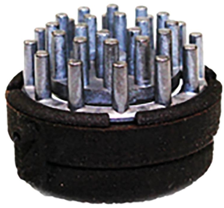
Figure 9.3 Electrode placements in BCI headset.
A combination of active sensors (sensors right at the electrode tip), with ultra-high impedance amplifiers and proprietary circuitry, and optimized Ag/AgCl electrode tips help record signal quality comparable to that obtained with wet electrode systems. Furthermore, the DSI streamer software that comes with the headset has the capability for continuous impedance monitoring to ensure good signal quality during recording.
The channels of the headset were arranged primarily over the motor and parietal cortical areas according to the international 10/20 system. The channel reference positions are FP1, FP2, FZ, F3, F3, F7, F8, CZ, C3, C4, T3, T4, T5, T6, P3, P4, O1, O2, A1, A2. The reference electrode was placed on Pzcmf.
9.3.3 EEG Signal Collection
The study aims to design a model to classify the EEG signal to control the wheelchair using four possible commands: Turn left, Turn right, Move forward, and Move backward. The EEG headset is placed on the subject’s head and adjusted to sit in the correct position, as shown in Figure 9.3. Through the DSI steamer software, the placement of the electrodes and the impedance level were monitored. The participants were instructed about the basics of EEG recording, such as blinking, and jaw clenching should be avoided during data collection.
Following the EEG headset placement, subjects were seated in a comfortable chair placed in a quite soundproofed room. Before each recording segment, subjects were instructed to assume a comfortable position in a chair. Other brain activities might suppress the desired signal. In order to obtain the alpha signal before the experimental task, subjects were instructed to close their eyes and to relax but to stay awake for a few seconds, and then the subjects were instructed to open their eyes to fixate on a multicolor subject at 1 m distance and to relax.
Data acquisition was divided into five parts, subjects were asked to imagine looking on the right side, the signal was collected for 120 seconds. Then after a few minutes of break, the same process was repeated for imaging looking on the left side, the signal was collected for 120 seconds, then in the third section, the subjects were asked to imagine moving straight for 120 seconds, and the signal was collected. Then to model the backward driving of the wheelchair, the subjects were asked to imagine moving backward on the left side, and the signal was collected for 60 seconds, and then the subjects were asked to imagine moving backward on the right side, and the signal was collected for 60 seconds.
There were around 36,000 rows of information collected for 2 minutes of reading from all 21 channels for each direction. So, totally around 3,024,000 data points were collected from each subject to implement the classification model.
9.4 Data Pre-Processing
Pre-processing is an essential step to prepare data and make it ready for training. Pre-processing of data is usually done for two main reasons: (i) identify the problems with the data and (ii) preparation for data analysis [9]. Common methods like outlier detection and removal, cleaning data, maintaining coherence are employed to identify the gaps in the data. One of the major problems with EEG data is the interference of artifacts. As mentioned earlier in section 9.2.1.1, EEG data is extremely prone to artifacts i.e. pollution by EOG and EMG data as shown in the Figure 9.4. The other issue that persists is the extremely high dimensional nature of the collected data. Due to this, the size and learnability of the existing patterns by the Machine Learning algorithms increases drastically. Thus dimensionality reduction helps in extracting more relevant information from big collections of data aimed at improving the performance of a pattern recognition system drastically [10]. Similarly reducing the complexity of the data while keeping the crux patterns intact by signal processing techniques, reduces the computational strain that is experienced to train the model. Let’s take a look at each of the pre-processing techniques.

Figure 9.4 Contamination of target EEG signals by the biological artifacts [21].
9.4.1 Artifact Removal
The lack of dealing with artifacts significantly reduces the performance of the BCI system in practical applications [11]. Thus, it’s important to recognize them and remove them. Many automated systems have been developed for rejection or removal of artifacts [20]. The general method for doing so, is to discard the severely distributed EEG segments. As such, this method has also been implemented for the Cerebro BCI system as an early pre-processing step. Since this rudimentary method doesn’t ensure the removal of artifacts in sparsely distributed EEG segments, methods such as CSP and Riemannian geometric techniques are also employed. Section 9.5.3. Elaborates the discussion on the same, further in the chapter. Several other novel methods have also been introduced where artifacts are considered as missing values and BTF (Bayesian-tensor factorization) methods are used to fill the gaps to complete the EEG segment [12]. Although, BTF method isn’t employed for the Cerebro system.
9.4.2 Signal Processing and Dimensionality Reduction
The recorded EEG data inherently is polluted with noise of various types generated by environmental, instrumental causes or even by the signal source. The presence of noise masks the target signal diminishing the relevant characteristics of the patterns associated with the EEG signal. Depending on the stage one’s in on the Data pipeline, filters are chosen to clip the noise [14]. In the pre-processing step, signals are filtered through a low-pass filter to extract the lower dimensional features. These features contain a more distinct representation of the underlying patterns. Butterworth low-pass filter is being implemented for Cerebro as it is tested positively across many BCI and EEG related literatures [13, 14]. Butterworth filter is essentially designed to obtain a flat frequency response in the passband. The above step also acts as a dimensionality reduction step. The changes in the EEG signal before and after are observed in the Figure 9.5. It is also to be noted that there are a few more methods such as SWT (stationary wavelet transform) which also work exceptionally well with EEG data [15].
9.4.3 Feature Extraction
The key question persists, what are the important features of the obtained EEG data that discriminate between any two given classes. This is important because, the higher the difference between the classes of motor imagery, the better the classification. As such, CSP (Common Spatial Pattern) feature extraction is used to find projections that maximize the discrimination between different classes [16] and a classification technique which exploits the structure of tangent space features drawn from the Riemannian geometry framework are employed [17].

Figure 9.5 Before and after applying Butterworth low-pass filter to an EEG signal corresponding to the class – “Right”.
The CSP method involves finding an optimal number of spatial filters from the given input data, to compute the features whose variances are optimal for discriminating between two classes of EEG recordings [19]. That is achieved by using the concept of diagonalization of the covariance matrix for both groups (any two given classes) simultaneously [18]. These covariances are generated using the pyriemann package which are then fitted on the data to produce the features. The following is the code which depicts the functions to perform the above tasks.

Covariance matrices computed through spatial filters as discussed above are largely used in NMI (Neural Motor Imagery) based BCI systems. Cerebro also employs it to yield improved results and efficiency of the classifier. These covariance matrices lie in SPD spaces (Symmetric Positives-Definite), which are a subset of the Riemannian Geometrical domain of computations [21]. As such tangent space features drawn from the Riemannian geometry framework that is shared among the training data of multiple subjects are exploited [18] to increase the classification efficiency and aid in removal of artifacts [22]. These are also generated using the pyriemann package as shown below.

9.5 Classification
Classification is an integral part of the Cerebro BCI system as it actively recognizes and classifies what movement has been imagined by the subject. While the end result of a trained model is deployed on a micro-computer, it is essential to understand the DL and the training process. A deep learning model trains over the EEG data obtained and finally when input a new EEG data, the model classifies the input by mapping it to corresponding class. The overview of the process is represented below (see Figure 9.6). The typical pipeline for the classification process involves a few prior steps which we have covered in previous sections. Check Figure 9.7 for a complete overview of the pipeline.

Figure 9.6 System level overview of the classification process.

Figure 9.7 Typical pipeline for classification models.
9.5.1 Deep Learning (DL) Model Pipeline
To test the performance of the cerebro system, two pipelines were constructed and tested accordingly, on the collected data. The motive for testing multiple DL pipelines was to compare the performance and efficiency of the system to be able to deploy on an end product. Each pipeline contains three specific stages. Preprocessing, Training and Cross Validation. To design BCI’s based on the CSP algorithm, the common preprocessing step involves extracting the covariance matrices of the EEG signal for each class (left, right, back etc.). This step also facilitates better handling of dimensionality. Common training paradigm used in all three pipelines includes a Support Vector Machine (SVM) as was found to be the best in several pre-established BCI related literatures. Although, variants of SVM kernels were used for each CSP method and the Riemannian geometry method. Finally, for the validation step, K-fold cross-validation (with five splits) was implemented for estimating the performance of the trained models, as was found to deliver results that are generally less biased in estimating the models’ skill, by several earlier literatures.
9.5.2 Architecture of the DL Model
As mentioned in the previous section, Cerebro leverages SVM’s for training on EEG data as they have been proven to work the best for BCI based multi-class classification [24]. SVM’s are fundamentally different from ANN’s (Artificial Neural Networks), as its core mechanisms are based on statistical and geometrical approaches as opposed to ANN’s which try to emulate the neural system of the human brain. SVM’s are used to perform both binary and multi-class classification tasks. While a linear binary SVM classification includes calculation of the optimal hyperplane decision boundary that separates one class from another, multi-class classification breaks down the problem into multiple sets of binary classifications for computing the decision boundaries [25]. In general two approaches i.e. (i) pairwise and (ii) one-versus-all classification paradigms are used for a multi-class problem. Figure 9.8 shows the mapping of input-space into a feature space with a division of binary classes by a linear hyperplane. Figure 9.9 depicts the resultant decision function of the SVM architecture after the computations of weights and support vectors have been completed in the training stage. For in depth understanding of SVM please refer to [26].

Figure 9.8 Non-linear-mapping from two-dimensional input space with non-linear class boundaries into a three-dimensional feature space with linear separation by a hyperplane. Courtesy of SVM article on http://www.neural-forecasting.com.

Figure 9.9 SVM classifier architecture [25].
Two kernels, linear and rbf (radial basis function) are offered for each CSP and Riemannian approaches of classification. Hyperparameters of each are shown in Table 9.3.
9.5.3 Output Metrics of the Classifier
The custom trained SVM with tuned hyper-parameters yields an average accuracy score of 0.7477175231044293 ~75% with the Riemannian Geometry technique and a 0.7382235458425794 ~74% with the CSP technique. This result is yielded over an average training period of 91.88 sec, 117.45 sec for CSP and Riemannian techniques respectively over 1000 epochs. It essentially means that the model predicts correctly what direction the subject (user) is thinking seven to eight times out of 10 on an average. The average precision and recall for each on average is 80%, 85% respectively for each technique. It is expected that given more training data collected from a diversified group of individuals and trained over a longer period of time, accuracy and precision score can potentially be improved significantly.
9.5.4 Deployment of DL Model
The trained model is finally deployed on the Raspberry Pi3 micro-computer. The EEG data read from the user will be served as input to this deployed model, which then predicts the imagined motion and takes necessary actions. The next section elaborates on the entire control system of Cerebro.
Table 9.3 Depicting the hyperparameter values of the different SVM kernels. Note that these are parameters of the SVM methods offered by the sklearn.svm package.
| Hyperparameter | C | Loss | max_iter | Multi_ class | Penalty | Random_ state | Gamma | Tol | Degree |
|---|---|---|---|---|---|---|---|---|---|
| Linear SVM | 0.1 | ‘hinge’ | 1000 | ‘ovr’ | l2 | 1 | default | 0.00001 | default |
| RBF SVM | 20 | default | -1 | ‘ovr’ | default | default | auto | 0.001 | 10 |
9.5.5 Control System
The Control system forms the topmost layer of the Cerebro system. The output from the Classification layer is transmitted to the Control system which maps the received signal to its respective control operation. This is the final stage of the BCI system where the natural efferent pathways are bypassed to achieve the desired action (control and communication). A Raspberry Pi3 Micro-computer is the central unit of the control system and responsible for collection and re-directing of all input signals. Detailed architecture of the entire Cerebro system will be elaborated in the next section. The control system offers two modes of operation, each for a specific application.
9.5.6 Control Flow Overview
A flip switch is fitted to shift from one mode to another. It must be noted that while operating Cerebro in one mode, the other cannot be accessed. This lock ensures the safety of the patient/user from any system mishap.
9.6 Control Modes
9.6.1 Speech Mode
In this mode, the user can essentially type out the words he/she intends to speak and then convert them into speech. This involves a two-step process. One where the patient is prompted to input text of interest and the other, converting the text into speech. Since the user is a disabled individual and can only leverage the power of the brain, Cerebro integrates the speech module (see Figure 9.10) with the main BCI system via blink recognition. The following sections take a detailed look into each of these systems.
9.6.2 Blink Stimulus Mapping
It is a known fact pre-established by several literatures that BCI’s are able to detect intentional eye blinks of a person based on their blink strength. This feature is utilized to map each intentional/pressured blink with the selection of a key on the automated keyboard. For example, in speech mode if the user intentionally blinks with a little pressure, the key with the cursor on it will be selected. This way, the disabled individual can type out entire words and sentences. Intentional Blink stimulus from the BCI is sent to the Raspberry Pi3 module which triggers the selection of key whenever the BCI sends a blink signal.

Figure 9.10 Complete system level overview of Cerebro.
9.6.3 Text Interface
An LCD interface is fitted onto the Raspberry Pi3 micro-computer which runs an automated python GUI keyboard interface. The cursor of the keyboard interface moves across the screen iterating over every key in a loop until one is selected by blinking. The layout of the keyboard can be observed in Figure 9.11. Preset sentences like “hey”, “how are you?”, “I am hungry”, “I am happy” and emergency sentences like, “Help me” are set to facilitate ease of access for the patient. A “talk” key is displayed on the keyboard interface, upon selection it converts the typed out text into voice using the python package gTTS API. And finally the speakers attached to the Cerebro Wheelchair present the speech output.
9.6.4 Motion Mode
In this mode of operation, the user is only able to control the wheelchairs’ movement and not the speech functionality. Motors attached to the wheelchair for its mobility are controlled by the motor driver which receives signals from the Raspberry Pi3.
9.6.5 Motor Arrangement
The arrangement of the motors is designed in such a way that the rear rotors (tires) are driven by the motors while the front is fitted with a castor wheel for ease of movement. The rotation axis and direction of the rear motors control the direction of movement of the Cerebro wheelchair. These motors are connected to the motor driver (L293D) which dictates the direction and the speed of the wheelchair. The motor driver in turn is connected to the raspberry pi which maps the prediction of imagined direction by the user to actual rotation of the motors to execute the imagined movement.

Figure 9.11 The automated cursor movement keyboard GUI displayed on the LCD operated by the Raspberry Pi.
9.6.6 Imagined Motion Mapping
The classifier in the Cerebro system predicts and categorizes what is imagined by the user into its respective class (left, right etc.). These predictions need to be executed in order for the wheelchair to move. The central system monitored and operated by the Raspberry Pi3 module receives the prediction results from the classifier by Bluetooth communication channel and based on the predicted class, certain commands are signaled to the motor driver which then executes them accordingly. Thus moving the motors to achieve the imagined motion.
9.7 Compilation of All Systems
The complete architecture of Cerebro is shown in Figure 9.11. The EEG records the brain waves and sends it to the raspberry pi where the deployed dl model predicts the imagined motion. If the Cerebro system is in Motion mode, this output is then transferred to the motor unit where a motor driver converts this data into a communication signal for the rear rotors to move in the predicted direction. In the case of Speech Mode, an automated keyboard GUI with preset sentences is displayed on the LCD panel where the user can select letters and form sentences by intentionally blinking. The BCI in this mode instead of capturing EEG records for movement, detects intentional blinks and sends the signal to the micro-computer where this signal is processed into a communication signal for the cursor to select the key when blinked. After forming a sentence, the user must select the “Talk” key from the keyboard to convert the typed out text into speech through a mounted speaker.
9.8 Conclusion
Cerebro proposes a novel coalition of DL based BCI technology and automated systems with speech facilities offering an all-round functionality for the disabled. Additional testing with more data is expected to improve its performance in recognizing the brain patterns with greater accuracy. With advancements and sincere effort by the researchers in this field day-by-day, better devices and products are to be expected, which can also potentially improve the overall design of the end product. To my knowledge as of today, cerebro marks the first effort to build a complete BCI go-to market product with speech support features aiding the unfortunate.
References
- 1. Block, N., The Journal of Philosophy. JSTOR, 90, 4, 181–193, 1993. www.jstor.org/stable/2940970.
- 2. Wolpaw, R., Birbaumer, N., McFarland, D.J., Pfurtscheller, G., Vaughan, T.M., Brain computer interfaces for communication and control. Clin. Neurophysiol., 113, 767–791, 2002.
- 3. Levine, S.P., Huggins, J.E., BeMent, S.L., Kushwaha, R.K., Schuh, L.A., Passaro, E.A., Rohde, M.M., Ross, D.A., Identification of electrocorticogram patterns as the basis for a direct brain interface. J. Clin. Neurophysiol., 16, 5, 439, September 1999.
- 4. Leeb, R., Friedman, D., Müller-Putz, G.R., Scherer, R., Slater, M., Pfurtscheller, G., Self-paced (Asynchronous) BCI control of a wheelchair in virtual environments: A case study with a tetraplegic. Comput. Intell. Neurosci., Article ID 079642, 8, 2007.
- 5. Li Y, Pan J, Wang F, Yu Z. A hybrid BCI system combining P300 and SSVEP and its application to wheelchair control. IEEE Trans Biomed Eng., 60, 11, 3156–3166, 2013 Nov. Epub 2013 Jun 20. PMID: 23799679.
- 6. Schomer, D. and Silva, F., Niedermeyer’s electroencephalography: Basic principles, clinical applications, and related fields, Wolters Kluwer Health, Lippincott Williams & Wilkins, Philadelphia, USA, 2012.
- 7. McFarland, D. and Wolpaw, J., Brain-computer interfaces for communication and control. Commun. ACM, 54, 5, 60–66, 2011.
- 8. Allison, B.Z., McFarland, D.J., Schalk, G., Dong Zheng, S., Jackson, M.M., Wolpaw, J.R., Towards an independent brain–computer interface using steady state visual evoked potentials. Clin. Neurophysiol., 119, 2, 399–408, 2008.
- 9. Famili, A., et al. Data preprocessing and intelligent data analysis. Intelligent data analysis., 1.1, 3-23, 1997.
- 10. ESANN 2014 proceedings. European Symposium on Artificial Neural Networks, Computational Intelligence and Machine Learning, Bruges, Belgium, pp. 23–25, April 2014, i6doc.com publ., http://www.i6doc.com/fr/livre/?GCOI=28001100432440.
- 11. Wagner, J.M., Dromerick, A.W., Sahrmann, S.A., Lang, C.E., Upper extremity muscle activation during recovery of reaching in subjects with post-stroke hemiparesis. Clin. Neurophysiol., 118, 1, 164–176, 2007, https://doi.org/10.1016/j.clinph.2006.09.022.
- 12. Zhang, Y., Zhao, Q., Zhou, G., Jin, J., Wang, X., Cichocki, A., Removal of EEG artifacts for BCI applications using fully Bayesian tensor completion. 2016 IEEE International Conference on Acoustics, Speech and Signal Processing (ICASSP), pp. 819–823, 2016.
- 13. Deo, A., Pandey, S.K., Joshi, A., Sharma, S.K., Shrimali, H., Design of a third order butterworth Gm-C filter for EEG signal detection application. 2018 25th International Conference “Mixed Design of Integrated Circuits and System” (MIXDES), pp. 361–365, 2018.
- 14. Shakshi, R.J., Brain wave classification and feature extraction of EEG signal by using FFT on lab view. Int. Res. J. Eng. Technol., 3, 1208–1212, 2016.
- 15. Butterworth Bandpass and Stationary Wavelet Transform Filter Comparison for Electroencephalography Signal S. S. Daud, R. Sudirman Department of Electronic and Computer Engineering Faculty of Electrical Engineering. 6th International Conference on Intelligent Systems, Modelling and Simulation, UTM 81310 UTM Johor Bahru, 2015.
- 16. Belhadj, S.A., Benmoussat, N., Della Krachai, M., CSP features extraction and FLDA classification of EEG-based motor imagery for brain-computer interaction. 2015 4th International Conference on Electrical Engineering (ICEE), pp. 1–6, 2015.
- 17. Gaur, P., Tangent space features-based transfer learning classification model for two-class motor imagery brain–computer interface. Int. J. Neural Syst., 29, 10, 1950025, 2019.
- 18. Afrakhteh, S. and Mosavi, M.R., Chapter 2 - Applying an efficient evolutionary algorithm for EEG signal feature selection and classification in decision-based systems, in: Energy efficiency of medical devices and healthcare applications, A. Mohamed (Ed.), pp. 25–52, Academic Press, London, United Kingdom, 2020, https://doi.org/10.1016/B978-0-12-819045-6.00002-9.
- 19. Lisi, G. and Morimoto, J., Chapter Seven - Noninvasive brain machine interfaces for assistive and rehabilitation robotics: A review, in: Human modelling for bio-inspired robotics, J. Ueda and Y. Kurita (Eds.), pp. 187–216, Academic Press, London, United Kingdom, 2017, https://doi.org/10.1016/B978-0-12-803137-7.00006-9.
- 20. Kanoga, S. and Mitsukura, Y., Review of artifact rejection methods for electroencephalographic systems. Electroencephalography, 69, 69–89, 2017.
- 21. Barachant, C., Riemannian geometry applied to BCI classification, in: Latent variable analysis and signal separation, pp. 629–636, Springer, Berlin Heidelberg, 2010.
- 22. Xu, J., Grosse-Wentrup, M., Jayaram, V., Tangent space spatial filters for interpretable and efficient Riemannian classification. J. Neural Eng., 17, 2, 026043, 2020.
- 23. Rajesh Kumar, D., Vinothsaravanan, R., Poongodi, M., Krishnasamy, L., Hamdi, M., Kotecha, K., Vijayakumar, V., Random forest bagging and x-means clustered antipattern detection from SQL query log for accessing secure mobile data, Wireless Communications and Mobile Computing, 2021, Article ID 2730246, 9 pages, 2021. https://doi.org/10.1155/2021/2730246
- 24. Schlögl, A. et al., Characterization of four-class motor imagery EEG data for the BCI-competition 2005. J. Neural Eng., 2, 4, L14, 2005.
- 25. Ruiz-Gonzalez, R., Gomez-Gil, J., Gomez-Gil, F.J., Martínez-Martínez, V., An SVM-based classifier for estimating the state of various rotating components in agro-industrial machinery with a vibration signal acquired from a single point on the machine chassis. Sensors., 14, 11, 20713–20735, 2014.
- 26. Joachims, T., Making large-scale SVM learning practical. EconStor: Making large-scale SVM learning practical, Practical Advances in Kernel Methods-Support Vector Learning, 1999, USA: MIT Press, Cambridge, MA, 1998. http://hdl.handle.net/10419/77178.
Note
- *Corresponding author: [email protected]