Chapter 7. Introduction to Arduino and NFC
As you’ve seen from Chapter 6, you can use NFC to initiate all kinds of action when you connect an NFC radio to devices that interface with the physical world. Although we relied on existing hardware in the previous chapter, we don’t always have to do so. For example, imagine you wanted to make the Mood Setter application do more than control lights and music. Perhaps you’d like it to open or close the window blinds, lock the door, or even set off fireworks. All of these things are possible with a custom controller, a few electronic and mechanical components, and an NFC radio. Smartphones and tablets aren’t the only devices that can use NFC. There are NFC modules on the market for microcontrollers as well. In this chapter, you’ll get a brief introduction to NFC on the Arduino microcontroller platform.
Digital Meets Physical: Arduino
If you’re interested in building new physical interfaces for electronic devices, you generally start with a microcontroller. Microcontrollers are the simple programmable computers at the heart of nearly every electronic device you own. The digital input and output pins of a microcontroller can read and generate electrical changes from sensors, or control other components like motors, lights, speakers, and more. The Arduino microcontroller platform makes it easy to begin developing your own microcontroller projects by combining a simple integrated development environment on the software side and a range of preassembled microcontroller interface boards on the hardware side.
Common Arduino projects include custom musical instruments, remote control pet feeders, environmental sensing projects, game controllers that afford different forms of action, and much more.
Both the Arduino software and hardware are open source. You can find the source code for the IDE, the source code for the firmware libraries, and the electrical schematics and board layout plans on the Arduino website.
An Arduino is a general-purpose microcontroller. Its input and output pins are not dedicated to any specific application. Think of it like the CPU of your mobile phone: though it’s programmable, it would be useless without the cellular radio, the screen controller, and the audio controller (not to mention the NFC controller). To make an Arduino useful, you need to connect it to more specific-purpose components, like communications radios, motor controllers, physical sensors, and so forth. The Arduino platform features a specification for add-on modules called shields that perform these various functions. For this chapter, you’ll connect an Arduino Uno, the most common Arduino model, to an NFC radio shield.
Although microcontrollers are often used to introduce electronics development, you won’t get much of that in this book. For the projects used here, you’ll use mostly pre-built electronic modules that can be controlled from the Arduino or other microcontrollers using one of the methods outlined. You won’t have to design or build your own circuits. You’ll use shields and other pre-built modules for your electronic needs, so you can focus on the mechanics of using NFC in the Arduino environment.
The Hardware Heart of NFC
At the heart of NFC communication is a radio controller. When reading passive targets like the tags you’ve used so far, the controller is the initiator. It generates the radio signal that the tag receives, then waits for a returned signal, as explained in Chapter 2. When communicating with active targets like a smartphone or tablet, the radio can be the initiator or the target. If it’s the target, it listens for incoming radio signals and responds. The controller acts like a modem: it controls the transmission and reception of radio signals and converts those signals to data communications with its central processor.
One of the most popular NFC controllers on the market right now is the NXP PN532. It’s common to a number of different NFC modules, and the PN53x family of controllers can be found in most of the NFC-enabled consumer devices on the market. There are several modules compatible with Arduino that use the PN532: the PN532 NFC/RFID controller breakout board v1.3 from Adafruit; the PN532 NFC/RFID Controller Shield for Arduino (also from Adafruit); and Seeed Studio’s NFC Shield and NFC Shield v2.0. All of these modules are compatible with the NDEF libraries you’ll use in this chapter.
In your Android device, the NFC controller is attached to the CPU’s I/O pins, and communicates with it using similar protocols to the ones you’ll use here. The NFC plug-in for PhoneGap serves the same purpose as the Arduino libraries you’ll see here: it allows the central processor of your Android device to control the NFC chip on the device.
The Arduino Development Environment
To do the exercises introducing Arduino, you’ll need the following:
- An Arduino Uno microcontroller, available from many outlets, including Arduino, Adafruit, Seeed Studio, and others
- The Arduino IDE
Tip
The libraries and examples for this chapter have been tested thoroughly on the Uno, but not the Due or the Leonardo. They should work well on any Arduino derivative that uses the Atmega328 processor. For the other processors, it might work, but you’re in uncharted territory.
Once you’ve downloaded and installed the Arduino IDE, open it and you’ll get an editor window containing the following code:
voidsetup(){// put your setup code here, to run once:}voidloop(){// put your main code here, to run repeatedly:}
The Arduino programming framework is written in C++, and the code you write for Arduino is as well. The framework simplifies the more complex aspects of the language, however. There are two main functions to every Arduino program: setup() runs once when the processor powers up or is reset, and loop() runs repeatedly from the end of setup() until the processor is disconnected from power or reset. There are no callbacks, no multiple threading, just one single loop. You can call functions from the loop, though, as you’ll see further on.
Here’s your first running program for Arduino:
constintled=13;// give the LED pin number a namevoidsetup(){pinMode(led,OUTPUT);// initialize pin 13 as an output}voidloop(){digitalWrite(led,HIGH);// turn the LED on (HIGH is the voltage level)delay(1000);// wait for a seconddigitalWrite(led,LOW);// turn the LED off by making the voltage LOWdelay(1000);// wait for a second}
After tying this in, pull down the Tools → Board menu and choose “Arduino Uno.” In the Tools → Serial Port menu (or Tools → Port in later versions of Arduino) you’ll see a list of serial ports. Unfortunately none of them will be named “Arduino,” but you can find the name of your port by looking at the list, then plugging your Arduino Uno into a USB port (on Windows you’ll be asked to install drivers; they’re included in the IDE download) and looking at the list again. The new port in the list will be your Arduino Uno. On OS X, you’ll see two ports, one labeled /dev/cu.usbmodem-xxx and another labeled /dev/tty.usbmodem-xxx, with xxx being the board’s serial number. Either one will work, as they’re functionally the same port. For example, on a 2011-era MacBook Air running OS X 10.8, the ports are called /dev/tty.usbmodem621 or /dev/tty.usbmodem421. On a Windows 7 or 8 machine, it’s COM3. On Linux, it’s usually /dev/ttyACM0.
Pick your port, then click the “Upload” button on the toolbar, as shown in Figure 7-1.

This figure also illustrates the Toolbar buttons; from the left, they are Verify (compiles your code), Upload (compiles and uploads), New, Open, and Save. On the far right is the Serial Port Monitor. The selected board type and serial port appear on the bottom right of the window. The IDE will compile your code and upload it to the board. The board will reset and start running, and you’ll see a blinking LED right next to the Arduino logo on the board (Figure 7-2). That LED is attached to one of the controller’s I/O pins, digital pin 13.

Arduino, like all microcontrollers, operates by reading or controlling the voltage on its I/O pins. The command digitalRead() returns a 1 or a 0 from a given pin, also called HIGH or LOW (referring to the voltage levels). The digitalWrite() command sets a given pin to HIGH or LOW. The Uno operates at 5 volts, so HIGH, or 1, refers to 5 volts, while LOW or 0 refers to 0 volts. Some of the I/O pins can operate in analog mode too: Analog pins A0 through A5 can read an analog voltage from 0 to 5 volts, with a resolution of about 0.05 volts (returns a range from 0 to 1,023). Digital pins 3, 5, 6, 9, 10, and 11 can “fake” a continuously changing analog output voltage by pulsing the pin with a duty cycle resolution of 256 steps.
In the previous code, the Arduino initializes digital pin 13 as an output pin, meaning it will drive voltage on that pin. In the loop, the processor sets the voltage to 5 volts (digitalWrite(ledPin, HIGH)), then to 0 volts (digitalWrite(ledPin, LOW)). In between, it does nothing for 1,000 milliseconds (delay(1000)). Because this is the only program running on the Arduino’s processor, delay() really means the processor does nothing, so you won’t see it used a whole lot.
The IDE creates a default directory for your sketches in your Documents directory called Arduino. For convenience, save this sketch there under the name Blink. You’ll see more on this sketch directory later.
The core Arduino command reference can be found at Arduino’s Language Reference page. There are also dozens of examples of how to use the platform in the Learning section. You can also find these examples in the IDE, by choosing Examples from the File menu.
Serial Communication
In addition to the basic I/O functions, the Arduino can communicate using asynchronous serial over USB, as well as the I2C and SPI protocols used by the PN532 chip. You’ll see serial-to-USB used a lot to send messages to and from your computer. It’s also used to upload your compiled program (called a sketch in Arduino) to the Uno. Here’s a sketch that reads input from your computer over the USB-to-serial connection and uses the input to control the output of the LED on pin 13:
constintled=13;// give the LED pin number a namevoidsetup(){Serial.begin(9600);// open serial communication at 9600 bpspinMode(led,OUTPUT);// make the LED pin an output}voidloop(){if(Serial.available()){charinput=Serial.read();// read a byte from the serial portif(input=='H'||input=='h'){// if it's H or hdigitalWrite(led,HIGH);// turn the LED onSerial.println(input);// echo what the user typed}elseif(input=='L'||input=='l'){// if it's L or ldigitalWrite(led,LOW);// turn the LED offSerial.println(input);// echo what the user typed}}}
The full source code can be found on GitHub.
Upload this sketch, then click the Serial Port Monitor on the right side of the toolbar and the Serial Monitor window will open. Type “H” or “h” and click “send” or hit Enter and the LED attached to pin 13 will turn on. Type “L” or “l” and it will turn off.
Once you understand digital in and out, analog in and out, and serial communication, you’ve got the basics of working with Arduino. Everything is controlled either by reading a voltage on an input pin, generating a voltage on an output pin, or sending digital communications using serial protocols. Serial protocols themselves are just timed series of voltage pulses on specific I/O pins.
For more information on developing projects with Arduino, see Massimo Banzi’s Getting Started with Arduino, Tom Igoe’s Making Things Talk, or Michael Margolis’ Arduino Bookbook, among others. You’ll also find thousands of Arduino example projects, sample code, libraries, and add-on modules on the Web.
Installing Arduino Libraries
The Arduino environment can be extended through the use of libraries, just like any programming platform. To use NFC with Arduino, you’ll need a couple of libraries. Download the NDEF library from Don’s GitHub repository. To install it as an Arduino library, click “Import Library…” in the Sketch menu, then choose the “Add Library…” submenu option. You can install the library from a ZIP file, or by choosing a directory and choosing “All Files.” In either case, the IDE will import all the files from the ZIP or directory. Inside each library directory is a subdirectory called “Examples.” After you import the library, these can be found in the File menu under “Examples,” with a submenu for the library’s name.
You’ll also need an adapter library for the shield you’re using. There are several different libraries for the PN532 chip, but in the examples that follow, you’ll be using the PN532 libraries from Seeed Studio. These will work with both Seeed’s shields and Adafruit’s shield. You can download them from Seeed’s GitHub repository. The Seeed Studio NFC libraries are separated into three different components: the PN532 folder, the PN532_I2C folder, and the PN532_SPI folder. In order to get them to work with Arduino 1.5 and beyond, you should import each of these three folders as if they were separate libraries. That way they’ll end up in the libraries folder properly, and when you compile your code, you’ll save some memory, because you won’t be adding the drivers for the communication protocol you don’t need.
Other Libraries, and Library Namespace Collisions
Adafruit’s NCFShield I2C library is also an excellent library for use with the PN532. You can download it from GitHub. Although the Adafruit library works only with the I2C interface, and therefore only works with the Adafruit shield, it is a very stable library, and takes a little less memory than the Seeed library. The Adafruit library doesn’t work automatically with the NDEF library for Arduino, but can be made to do so with some slight modifications to the latter.
If you’ve experimented with some of the lower-level NFC libraries previously, and still have earlier versions of them in your libraries folder (like we did), you may get errors when you try to compile your code. If you do, remove any libraries related to the PN532 that you’re not using from your Arduino libraries directory and restart the IDE. You can find the libraries directory inside your Arduino sketch directory.
For these examples, you’ll need the following:
- An Arduino Uno microcontroller.
- The Arduino IDE.
- An NFC Shield (you can use Adafruit’s PN532 NFC/RFID Controller Shield for Arduino or Seeed Studio’s NFC Shield or NFC Shield v2.0)
- If you’re using the Adafruit shield, you may want to get some Shield Stacking headers from Adafruit as well. You’re going to have to do a little soldering to use this shield, but it’s worth it.
- A few NFC tags (for this chapter, Mifare Classic are the most compatible with the Arduino libraries you’re using, even though they won’t work on some Android devices; see Device-to-Tag Type Matching for more on which tags work with which devices).
- The Arduino IDE version 1.5.3 or later.
- The Arduino NDEF library, available from Don Coleman’s GitHub repository.
- The SeeedStudio PN532 library.
The Adafruit shield comes without pin headers mounted, so you’ll need to solder these on. It can be tricky to align these, but Adafruit’s got a nice tutorial with pictures linked off the product page on how to do this. Plug your shield into your Arduino Uno (it will only fit one way), and you’re ready to go.

The Arduino NDEF Library
The libraries you’re using can be thought of as a stack. The PN532 adapter libraries provide the low-level commands to speak to the PN532 chip on the shield, one in SPI and the other in I2C. By themselves, they simply deliver the data from the tags as a string of bytes. In order to interpret those bytes, you need some helper libraries that describe the various tag protocols: Mifare Classic, Mifare Ultralight, and so forth, as described in Chapter 2. Above the tag type libraries is an NFC layer that removes the differentiation between tags and delivers a stream of bytes. Finally, above that, there’s the NDEF library that reads the bytes passed on from the tag type libraries as a series of NDEF messages and records. Figure 7-4 shows the stack and the libraries’ relationships to each other.
Without the NDEF library, you’d have to figure out byte-by-byte what’s going on with the bytes coming in from your tags. With it, you can generally ignore what’s going on at the lower levels, and concentrate on reading and writing NDEF messages as you’ve done previously.
Not all the tag type helper libraries have been written. So far, the NDEF library repository includes tag libraries for reading and writing to Mifare Classic tags and read capability for Type 2 (Mifare Ultralight), but not the others, so you’ll need to use one of those two tag types, or be prepared to dive in and write your own tag descriptor library.

The NDEF library for Arduino contains some objects and concepts that should be familiar to you already:
- NfcAdapter
- This object is an instance of the lower level adapter library. It looks for tags for you.
- NfcTag
- This object contains metadata about the tag: UID, technology, and size.
- NdefMessage
- When you’ve read an NDEF-formatted tag, you’ll get an NdefMessage, of course. This object handles the encoding and decoding of bytes to and from the NDEF format.
- NdefRecord
- This carries the payload and any record metadata, like the language, the TNF, the Type, and so forth.
The library has a number of helper functions for both reading messages and writing them. You won’t use all of these functions, but most of them should seem familiar based on what you know of NDEF already. All the functions are listed by class in Table 7-1.
| NfcAdapter functions | NfcTag functions | NdefMessage functions | NdefRecord functions |
|
|
|
|
|
|
|
|
|
|
|
|
|
|
|
|
|
|
| |
|
|
| |
|
| ||
|
| ||
|
| ||
| |||
| |||
|
Reading NDEF in Arduino
The ReadTagExtended example that comes with the NDEF library shows many of the functions of the library and the workflow nicely. To see it, click the File menu, choose “Examples,” then the “NDEF” submenu, then “ReadTagExtended.” Upload it to your Arduino and try reading some of the tags you’ve already written.
You’ll need to change the beginning of the sketch depending on which shield model you’re using. If you’re using an SPI-based shield like the Seeed Studio shields, your code should start like this:
#include <SPI.h>#include <PN532_SPI.h>#include <PN532.h>#include <NfcAdapter.h>PN532_SPIpn532spi(SPI,10);NfcAdapternfc=NfcAdapter(pn532spi);
If you’re using an I2C-based shield like the Adafruit shield, your code should start like this:
#include <Wire.h>#include <PN532_I2C.h>#include <PN532.h>#include <NfcAdapter.h>PN532_I2Cpn532_i2c(Wire);NfcAdapternfc=NfcAdapter(pn532_i2c);
After that, everything will be identical, regardless of your shield type. The remainder of this chapter shows code for an I2C-based shield, so you should change the beginning as necessary if you’re using an SPI-based shield.
As you can see from the following code, the program logic is similar to what you’ve seen before: first you check if a tag is present using nfc.tagPresent(). Since Arduino doesn’t have event handlers, repeated polling is necessary for this. When you know there’s a tag, you make a tag object and read the data into it using NfcTag tag = nfc.read(). Next you check if there’s a message using tag.getNdefMessage(). If there’s a message present, iterate over the records in the message and pull out the message attributes (TNF, type, payload, and ID):
#include <Wire.h>#include <PN532_I2C.h>#include <PN532.h>#include <NfcAdapter.h>PN532_I2Cpn532_i2c(Wire);NfcAdapternfc=NfcAdapter(pn532_i2c);voidsetup(){Serial.begin(9600);Serial.println("NDEF Reader");nfc.begin();}voidloop(){Serial.println("Scan a NFC tag");if(nfc.tagPresent()){NfcTagtag=nfc.read();Serial.println(tag.getTagType());Serial.("UID: ");Serial.println(tag.getUidString());if(tag.hasNdefMessage()){// every tag won't have a messageNdefMessagemessage=tag.getNdefMessage();Serial.("This NFC Tag contains an NDEF Message with ");Serial.(message.getRecordCount());Serial.(" NDEF Record");if(message.getRecordCount()!=1){// if there's more than one record, pluralize:Serial.("s");}// cycle through the records, printing some info from eachintrecordCount=message.getRecordCount();for(inti=0;i<recordCount;i++){Serial.("NDEF Record ");Serial.println(i+1);NdefRecordrecord=message.getRecord(i);Serial.(" TNF: ");Serial.println(record.getTnf());Serial.(" Type: ");Serial.println(record.getType());// will be "" for TNF_EMPTY// The TNF and Type should be used to determine// how your application processes the payload// There's no generic processing for the payload.// it's returned as a byte[]intpayloadLength=record.getPayloadLength();bytepayload[payloadLength];record.getPayload(payload);// Force the data into a String:StringpayloadAsString="";for(intc=0;c<payloadLength;c++){payloadAsString+=(char)payload[c];}Serial.(" Payload (as String): ");Serial.println(payloadAsString);// id is probably blank and will return ""Stringuid=record.getId();if(uid!=""){Serial.(" ID: ");Serial.println(uid);}}}}delay(3000);// delay before next read}
Upload this code then open the Serial Port Monitor by clicking the icon on the top right corner of the IDE window. When you run this with the tags from previous chapters, you should get output that looks something like this:
NDEF Reader
Found chip PN532
Firmware ver. 1.6

Scan a NFC tag

Mifare Classic
UID: A4 AF 77 5D

This NFC Tag contains an NDEF Message with 2 NDEF Records
NDEF Record 1
  TNF: 2
  Type: text/hue
  Payload (as String): {"lights":{"1":{"name":"Living room","state":
   {"on":true,"bri":223,
   "hue":47293,"sat":0}}

NDEF Record 2
  TNF: 1
  Type: U
  Payload (as String): /sdcard/myMusic/Forever.mp3
The tagPresent and delay functions are blocking functions. This means they stop the program until they complete; about 100 milliseconds for tagPresent, and as long as you set for delay. You should only call them when your controller needs to do nothing else. If you need to read physical inputs like pushbuttons or receive data via serial communications, prioritize those things, as you’ll see in the application sketches that follow.
Writing NDEF in Arduino
Writing records to an NDEF message and sending it is also straightforward. The WriteTagMultipleRecords example gives you a good idea. To see it, click the File menu, choose “Examples,” then the “NDEF” submenu, then “WriteTagMultipleRecords.” Upload it to your Arduino and try writing to a tag, then reading it with your phone.
First, you set up an NdefMessage object, then you add records to it using the writing helper functions, such as addTextRecord(), addUriRecord(), or addMimeMediaRecord(). Once the message is assembled, you send it using the NfcAdapter write() function, which will return success or failure:
#include <Wire.h>#include <PN532_I2C.h>#include <PN532.h>#include <NfcAdapter.h>PN532_I2Cpn532_i2c(Wire);NfcAdapternfc=NfcAdapter(pn532_i2c);voidsetup(){Serial.begin(9600);Serial.println("NDEF Writer");nfc.begin();}voidloop(){Serial.println("Place a formatted Mifare Classic NFC tag on the reader.");if(nfc.tagPresent()){NdefMessagemessage=NdefMessage();message.addTextRecord("Hello, Arduino!");message.addUriRecord("http://arduino.cc");message.addTextRecord("Goodbye, Arduino!");booleansuccess=nfc.write(message);if(success){Serial.println("Success. Try reading this tag with your phone.");}else{Serial.println("Write failed");}}delay(3000);}
Once you’ve got a sense of the basic reading and writing functionality of the NDEF library, you’re ready to build an application with it.
A Microcontroller NFC Application: Hotel Key Cards
If you’ve checked into a hotel in the last 10 years, chances are good you had an RFID-based room key card. This is an application that could easily be enhanced through the use of NFC, so as an example of embedded NFC, you’ll build a simple NFC-based hotel room key card application. In this application, you’ll write an NFC card writer sketch on an Arduino as well as an NFC card reader sketch. The latter will involve an extra piece of hardware: an electronically controlled door lock that you can use in a real door if you want. Because what’s the fun of using a microcontroller if you can’t make something physical happen?
The first half of this application you’ll write is the tag writer in Arduino. You’ll make a little box that sits behind the registration desk, attached to the desk computer. The clerk enters your name, room number, and how many nights you’re staying, then inserts the card in the box. The tag writer sketch then writes this information to the tag as a MIME media record containing a JSON string.
The second half of the application that you’ll write is the door lock controller. The Arduino will be attached to the door lock, and when it reads the card, it will check to see if the current time is in between check-in and checkout, and if the room number on the card corresponds to the room number of the door. If that’s all correct, then the Arduino will open the door latch for three seconds so you can open the door.
Finally, you’ll write a browser-based user interface to connect with the NFC tag writer so that the desk clerk can interact with the device in a familiar way.
While the first half of the application could be written on a mobile device using the methods you’ve learned already, the second half requires a controller because of the physical door lock. You also have to consider the physical context in which it’s used. For example, a hotel guest is typically juggling a few items when she opens her room: suitcase, coat, purse or briefcase, and room key. You can’t expect her to do more than tap or insert the key, and you’ve got to make sure the door locks behind her.
For this application, you’ll need the same parts you needed for the preceding NFC examples. In addition, you’ll need some new parts:
A solderless breadboard or prototyping shield for Arduino. Here are a few options:
- Arduino Proto Shield Rev3.
- Adafruit Proto Shield for Arduino.
- A tiny breadboard (optional accompaniment to the previous two).
- If you don’t need everything mounted together, you can just use a half-size breadboard.
- A solenoid-driven door lock, 12 volts or less. There are plenty of small solenoids that’ll do the job. We used an Amico 0837L DC 12V 8W Open Frame Type Solenoid for Electric Door Lock bought on Amazon, but you can also get solenoids from other retailers. Adafruit sells a similar lock-style solenoid and Seeed Studio sells several models, so if you’re ordering a shield from them, you can get a solenoid from them as well.
- A TIP120 Darlington transistor.
- A 12V, 1000mA power supply, with 2.1mm ID, 5.5mm OD, center-positive connector to power the solenoid circuit.
- jumper wires or 22AWG solid-core wire.
- Two LEDs (one red, one green). These are available from any electronics retailer, but for reference, check out Adafruit’s red LED pack or green LED pack.
- Two 220Ω resistors for the LEDs, which are available from any electronics retailer.
- The Time library for Arduino by Michael Margolis.
If you plan to build and deploy both the NFC writer and the NFC reader/lock controller, you’ll need two Arduinos and two NFC shields. However, you can learn the whole application with just one of each.
Figure 7-5 shows the system diagram for the application.

The Interaction and Data Format
Both of the controllers in this application, the card writer and the reader/door lock control, should be as responsive as possible, so it’s best to keep them as simple as possible. As you can see from the diagram, the writer will always be attached to a personal computer, which has a much richer physical interface. So you can leave the work of taking user input, working out the timestamps, and prompting the user to that computer. The microcontroller only needs to wait for a string of data, write it to the card, and report whether it succeeded or not. It won’t care what the data is, it’ll just write the text. To make things more compatible with other applications in this book, make the MIME media record a JSON string containing the basic details, like so:
{name:username,room:(roomnumber),checkin:(checkintimeinunixtime),checkout:(checkouttimeinunixtime),}
The writer sketch will wait for a serial string ending in a } character, then look for a tag in its field. If it sees a tag, it will write the string to the tag as an NDEF message with one NDEF MIME media record. If it succeeds, it will turn on a green LED on pin 9, and if it fails, it will turn on a red LED on pin 8. It will check every three seconds, and turn off both LEDs.
The reader sketch needs to be a bit more complex, because it’s a standalone device not attached to any other computer. It will need to keep time for itself, read and decode the tag data, check the current time against the check-in and checkout times, check the room number on the tag against its own number, and indicate to the user whether it read the tag, and control the lock appropriately.
The reader’s main loop has to be very responsive, however. Its primary task is listening for tags. When it’s not listening for tags, it should turn on an indicator LED, green or red, to indicate whether it got a good or bad read. If it’s a good read, it should also hold the door lock open.
Because you’re using JSON for the data exchange, you could add in other features as well. You could write a PhoneGap app for the guest, to display the room number and check-in and checkout times. You could write a series of room entry and exit times to the card. The advantage to this architecture is that it makes it trivial to add other information to the card and to applications on other physical devices that read it, while not affecting the most important device—the lock—at all.
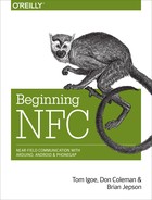
The Arduino NDEF Writer Device
The circuit for the NDEF writer is shown in Figure 7-6. It plugs into the Arduino, and the circuit shown sits on top of the shield (which is not pictured). It contains two LEDs and the NDEF shield. Connect the solenoid circuit as shown. You should test the LEDs by using the previous Blink sketch; just change the output pin number from 13 to 8 or 9 and upload the code again. The LED should blink.
See Figure 7-7 for a picture of the NDEF writer in schematic view.

Start with the writer code, as it’s simpler, and you’ve already got applications on your Android device that you can use to check it. Include the libraries you need and set up an NfcAdapter object. Then add some constants to name your output pins and a string for serial input, and a variable to track when you turn the indicator LEDs on, as you’ll see in the following sketch. Then in the setup, initialize serial communications and the NfcAdapter object, and set the two indicator LED pins to be outputs.
// If you're using an SPI-based shield, change these to include the SPI library:#include <Wire.h>#include <PN532_I2C.h>#include <PN532.h>#include <NfcAdapter.h>#include <Time.h>PN532_I2Cpn532_i2c(Wire);NfcAdapternfc=NfcAdapter(pn532_i2c);constintgreenLed=9;// pin for the green LEDconstintredLed=8;// pin for the red LEDStringinputString="";// string for input from serial portlonglightOnTime=0;// last time the LEDs were turned on, in msbooleanreadyToWrite=false;// true when you are ready to write to NFC tagvoidsetup(){Serial.begin(9600);// initialize serial communicationsnfc.begin();// initialize NfcAdapterpinMode(greenLed,OUTPUT);// make pin 9 an outputpinMode(redLed,OUTPUT);// make pin 8 an output}
The main function of the loop is to take input serially from a desktop app on a personal computer. When you’ve got the data, you’ll call another function to look for a tag and write to it. Here is the main loop:
voidloop(){// if there's incoming data, read it into a string:while(Serial.available()>0){charthisChar=Serial.read();// add incoming character to the end of inputString:inputString+=thisChar;if(thisChar=='{'){// new message, reset bufferinputString="{";readyToWrite=false;}elseif(thisChar=='}'){// end of message, ready to write to tagSerial.println("Ready to write data to tag");readyToWrite=true;}}// keep looking for a tag to write to when// you've got a string to write:if(readyToWrite){lookForTag();}if(millis()-lightOnTime>3000){// check every three secondsdigitalWrite(greenLed,LOW);// turn off pin 9digitalWrite(redLed,LOW);// turn off pin 8}}
The if statement at the end of the main loop uses the millis() function, which returns the number of milliseconds since the Arduino reset to check if three seconds have elapsed since you turned on the success or failure LED. If so, it turns them both off.
The lookForTag() function that’s called when you have a full string looks for a tag and writes the input string to it. When there’s a valid string to write, the main loop calls lookForTag() continuously until it succeeds. If lookForTag() succeeds in writing to the tag, it returns true. Otherwise, it returns false:
voidlookForTag(){if(nfc.tagPresent()){// if there's a tag presentNdefMessagemessage;// make a new NDEF message// add the input string as a record:message.addMimeMediaRecord("text/hotelkey",inputString);booleansuccess=nfc.write(message);// attempt to write to the tagif(success){// let the desktop app know you succeeded:Serial.println("Result: tag written.");digitalWrite(redLed,LOW);// turn off the failure light if ondigitalWrite(greenLed,HIGH);// turn on the success lightlightOnTime=millis();readyToWrite=false;// clear write flag}else{// let the desktop app know you failed:Serial.println("Result: failed to write to tag");digitalWrite(greenLed,LOW);// turn off the success light if ondigitalWrite(redLed,HIGH);// turn on the failure lightlightOnTime=millis();}}}
This function also sends a serial response whether it succeeded or failed to write to the tag, and both responses contain a common word, Result:. That’s important, because it means a desktop application that’s reading this response can parse for the line easily, whether the tag was written or not.
The full source code can be found on GitHub.
That’s the whole sketch. Save this, upload it to your Arduino, and test it by opening the Serial Port Monitor, placing a tag on the shield’s antenna and typing in the following JSON object (you may want to type it into a text document beforehand and cut and paste, and feel free to set your own values for these):
{
   "name":"Nicky",
   "room":3327,
   "checkin":1357534800,
   "checkout":1373428800
}
When you enter the data, the green LED should turn on, and you should get the message “Result: tag written.”
To test these tags, open any tag-reading app you have on your Android device, like NXP TagInfo, and try to read the tag. You should get a MIME media record with the same JSON string in it.
Your reader device doesn’t have a user interface, other than the green and red LEDs. It relies on a desktop application that can read and write its serial protocol to provide an interface for the desk clerk. You wouldn’t want the clerk to have to open the Arduino IDE and the Serial Port Monitor and type in a JSON string to write to the card. Instead, you’d write your desktop application to take input from the keyboard, convert it into a JSON string, and send it to the Arduino.
You could write a desktop interface in any programming environment that can access the serial ports of your computer. The clear serial communications protocol you established previously will help, namely that:
-
Every message to the writer device should be a JSON string, ending in
} - Every response from the writer device will contain the word “Result:” to report success or failure in writing to a tag
-
Every response from the writer ends in a new line (because you used
Serial.println())
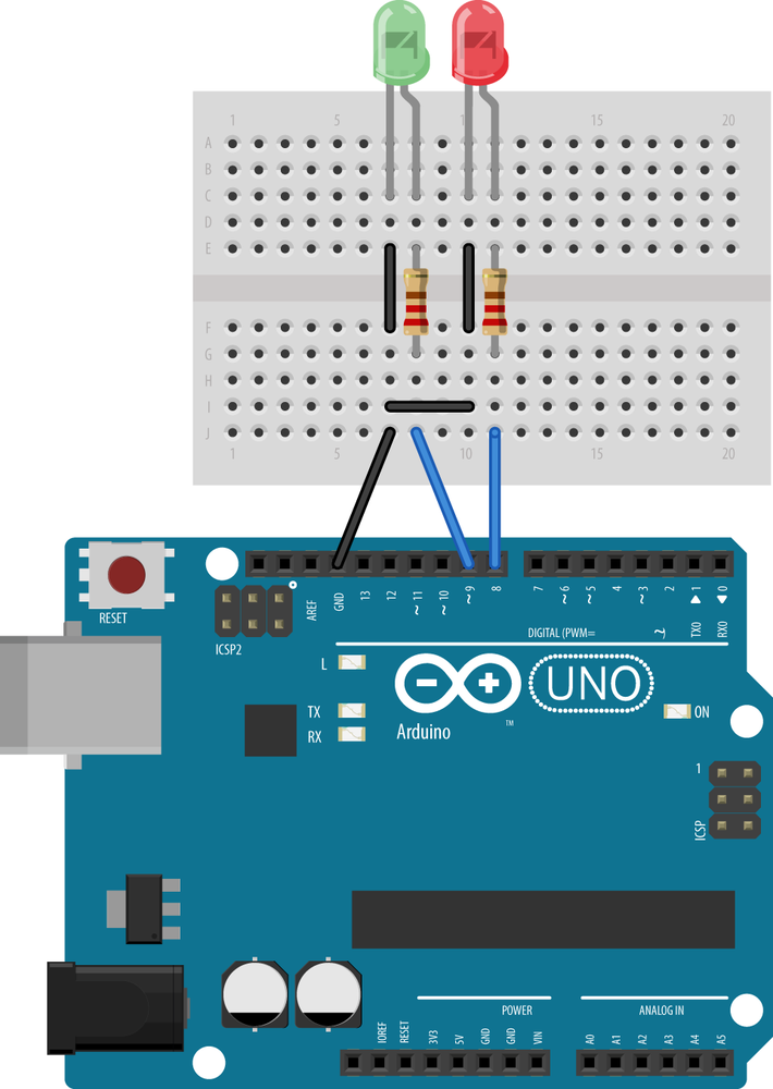
You’ll write a browser-based interface for this device in Node.js later on, but for now, move on to the reader device. You can see the writer device on a door in Figure 7-8. The dotted lines show where a control box and solenoid might be embedded in the door in a final version. The card would insert into a slot from the top or tap on the front of the reader as in most hotel rooms.
The Arduino NDEF Reader and Door Lock Device
The NDEF reader device is a bit more complex than the writer. It has to interpret the JSON on the tags and take appropriate action. In order to do that, it has to not only read the tag, but parse the result. It has to know if you’re at the right room number, and whether or not the current time is within the dates of your stay. To do this, it has to be able to tell time in Unix time. Michael Margolis’s Time library for Arduino will help accomplish this. Originally written to interface with a real-time clock (RTC) chip like the Dallas Semiconductor DS1307 or the DS3231, this library can also keep time using the Arduino’s internal clock. The latter is less accurate, but requires no extra hardware. It will do fine for this example.
The circuit for the reader is shown in Figure 7-9 with a solenoid lock (the NFC shield is not shown). It plugs into the Arduino and contains two LEDs, the NFC shield, and the solenoid circuit for the door lock part. Connect the solenoid circuit as shown. Note that, because the solenoid needs 12 volts and 667 milliamps to operate, you’ll need to power the Arduino from the 12V power supply mentioned in the parts list. You should test the solenoid by using the previous Blink sketch; just change the output pin number from 13 to 7 and upload the code again. The solenoid should fire once a second. Note that the MOSFET transistor here can be swapped with a TIP120 Darlington transistor, as they have the same pinout.

See Figure 7-10 for a picture of the same circuit in schematic view.

As you did with the writer, start your Arduino sketch for the reader with library includes, constants, and global variables. In addition to instantiating the NfcAdapter, you also need to create an instance of the Time library. Use constants to give names to the output pins and the lock’s room number, then add variables for the information from the card, like check-in time, checkout time, and whether or not your last card read was good:
// If you're using an SPI-based shield, change these to include the SPI library:#include <Wire.h>#include <PN532_I2C.h>#include <PN532.h>#include <NfcAdapter.h>#include <Time.h>PN532_I2Cpn532_i2c(Wire);NfcAdapternfc=NfcAdapter(pn532_i2c);constintlockPin=7;// pin that the solenoid door lock is onconstintgreenLed=9;// pin for the green LEDconstintredLed=8;// pin for the red LEDconstlongroomNumber=3327;// the room numbertime_tcheckin=0;// checkin timetime_tcheckout=0;// checkout timeStringcardName="";// name on the cardlongcardRoomNumber=0;// room number on the cardlongreadTime=0;// last time you tried to read a cardbooleangoodRead=false;
The setup() function initializes your output pins as usual, and initializes the nfcAdapter and serial communications. It also sets the time. Make sure to change the time values to reflect the current date:
voidsetup(){Serial.begin(9600);// set the clock to the date & time// hour (24-hour format), minute, second, day, month, year.// e.g. date shown here is Jan 9 2013, midnight:setTime(00,00,00,1,9,2013);nfc.begin();// initialize the NFC readerpinMode(lockPin,OUTPUT);// make the door lock pin an outputdigitalWrite(lockPin,LOW);// set it low to lock the doorpinMode(greenLed,OUTPUT);// make pin 9 an outputpinMode(redLed,OUTPUT);// make pin 10 an outputSerial.println(F("Hotel NDEF Reader"));
Serial.(F("Current Hotel Time is "));Serial.println(formatTime(now()));Serial.(F("This is the lock for room "));Serial.println(roomNumber);}
-
The
Serial.print(F());notation writes these constant strings to flash memory to preserve program memory.
The loop checks how many milliseconds have passed since the last card read, using the millis() function, that returns how many milliseconds since the Arduino was reset. If it’s less than 3 seconds (3,000ms), then the lock and indicator LEDs are turned on or off, as appropriate, depending on the state of the last card read.
If more than three seconds have passed since the last card read (good or bad read), the loop calls a function to listen for tags:
voidloop(){if(millis()-readTime<3000){// less than three seconds since last tagdigitalWrite(greenLed,goodRead);// green LED lights for a good readdigitalWrite(lockPin,goodRead);// lock opens if you get a good readdigitalWrite(redLed,!goodRead);// red LED lights if you don't}else{// after three seconds, lock againdigitalWrite(greenLed,LOW);// turn off green LEDdigitalWrite(redLed,LOW);// turn off red LEDdigitalWrite(lockPin,LOW);// lock doorgoodRead=listenForTag();// listen for tags}}
The listenForTag() function does just that: listens for tags using the NfcAdapter’s tagPresent() function. If a tag shows up, and it if has an NDEF message, a for loop cycles through the records, reading them one by one. In this case, there will be only one record. Once you know the record’s length, you can set up a byte array to hold it, and copy the record into the array using getPayload(). Once you’ve converted the byte array into a String, you need to go through it and get the relevant parts out so that you can determine the guest name, room number, check-in date, and checkout date. That’s handled by a method called parsePayload(), which you’ll see further down:
booleanlistenForTag(){booleanunlockDoor=false;resetValues();if(nfc.tagPresent()){// if there's a tag presentreadTime=millis();// timestamp the last time you saw a cardNfcTagtag=nfc.read();if(tag.hasNdefMessage()){// every tag won't have a messageNdefMessagemessage=tag.getNdefMessage();NdefRecordrecord=message.getRecord(0);if(record.getTnf()==TNF_MIME_MEDIA&&record.getType()=="text/hotelkey"){// Get the length of the payload:intpayloadLength=record.getPayloadLength();bytepayload[payloadLength];// make a byte array to hold the payloadrecord.getPayload(payload);// convert the payload to a StringStringjson="";for(intc=0;c<payloadLength;c++){json+=(char)payload[c];}parsePayload(json);// parse the payload// check if you can let them in or not:unlockDoor=isValidKey();}}}returnunlockDoor;}
To parse the payload for the relevant data, you need to iterate over the record and look for the key/value pairs from the JSON object it contains. Start by finding the position of the opening and closing brackets. Within that, the key-value pairs are separated by commas, with a colon in the middle of each one. So if you know the position of the current comma, the last one, and the colon in between, you can extract each key/value pair. There is no comma after the last pair, so when you can’t find another comma, you’re on the last one:
voidparsePayload(Stringdata){// you only care about what's between the brackets, so:intopeningBracket=data.indexOf('{');intclosingBracket=data.indexOf('}');// your individual data is between two commas:intlastComma=openingBracket;intcomma=0;// parse the data until the last comma:while(comma!=-1){Stringkey,value;intcolon=data.indexOf(':',lastComma);// get the next coloncomma=data.indexOf(',',colon);// get the next comma// key is between the last comma and the colon:key=data.substring(lastComma+1,colon);// if there are no more commas:if(comma==-1){// value is between colon and closing:value=data.substring(colon+1,closingBracket);}else{// value is between colon and next comma:value=data.substring(colon+1,comma);}
Once you’ve got the key/value pairs, you need to throw away the quotation marks. A quick way to do that is to convert them to spaces using String.replace(), then trim the whitespace from the string using String.trim():
// now to get rid of the quotation marks:key.replace("""," ");// replace any " around the key with spaceskey.trim();// trim away the spacesvalue.replace("""," ");// replace any " around the value with spacesvalue.trim();// trim away the spaces
// now, look for the possible data you care about:setValue(key,value);lastComma=comma;}}
Once you’ve got the key/value pair, make a function called setValue() to check which pair it is and set the appropriate global variable. The name value needs to be kept as a string, the room number as an integer, and the check-in and checkout are of type time_t (which is just a 32-bit integer) for comparison to the current time. The String class has a handy function for parsing these strings into integers:
voidsetValue(StringthisKey,StringthisValue){if(thisKey=="checkout"){checkout=thisValue.toInt();}elseif(thisKey=="checkin"){checkin=thisValue.toInt();}elseif(thisKey=="name"){cardName=thisValue;}elseif(thisKey=="room"){cardRoomNumber=thisValue.toInt();}}
The next function you need for this sketch is the isValidKey() function, which is called from the listenForTags() function. This takes the check-in time (called arrival in the function’s parameters), and the departure (called departure) and compares them to the current time. If you’re within the guest’s window of stay, this function returns true. Otherwise, it returns false:
booleanisValidKey(){booleanresult=false;if(cardRoomNumber==roomNumber){if(now()<=checkin){Serial.println("You haven't checked in yet.");Serial.println("Current time "+formatTime(now()));Serial.println("Your arrival "+formatTime(checkin));}elseif((now()>=checkin)&&(now()<=checkout)){Serial.println("Welcome back to your room, "+cardName+".");result=true;}elseif(now()>=checkout){Serial.println("Thanks for staying with us! You've checked out.");Serial.println("Current time "+formatTime(now()));Serial.println("Your departure "+formatTime(checkout));}}else{Serial.("This card can't unlock room ");Serial.(roomNumber);Serial.println(".");}returnresult;}
There are plenty of serial messages in this function, but they are just for debugging purposes, since the actual device has no serial interface. If you want to save memory, you could comment out all of these serial messages once you know the sketch works. The only part that matters for the physical user interface is the part that sets the result to true or false. Here is the simplified version without the serial messages:
booleanisValidKey(){booleanresult=false;if(cardRoomNumber==roomNumber){if((now()>=checkin)&&(now()<=checkout)){result=true;}}returnresult;}
There is one other utility function to this sketch that takes a time variable and formats it as a string for printing. Again, if you’re looking to minimize the code, this function and the calls to it could be commented out once you know the sketch works properly:
StringformatTime(time_ttime){TimeElementselements;breakTime(time,elements);Stringformatted="";formatted+=elements.Month;formatted+="/";formatted+=elements.Day;formatted+="/";formatted+=elements.Year+1970;formatted+=" ";formatted+=elements.Hour;formatted+=":";formatted+=elements.Minute;returnformatted;}
The full source code can be found on GitHub.
You set the time back in the setup function, and so long as the time you set is between the times you wrote to the tag, the lock will open. Upload this sketch three times, changing the setTime() parameters in the setup function each time, and see what happens. Pick times that are before, in between, and after the check-in and checkout dates. If you used the sample JSON shown at the end of the Tag Writer example, your check-in is January 7, 2013, and your checkout is July 10, 2013.
A Browser Interface for the Arduino NDEF Writer Device
As you can see, it’s not easy to type the guest’s record into the Serial Port Monitor as a JSON object. What you need is a desktop application that can send messages through the serial port to the tag writer device. It would be nice if you could simply write an HTML page to take form input and send it out the serial port.
Most desktop programming languages provide an external library to access the hardware ports of your computer. However, web browsers generally don’t provide that functionality to protect devices attached to your computer from damage wrought by code from external websites. But when the server application that’s serving the pages is resident on your computer, you can access the hardware ports relatively safely.
Node.js bears a lot of conceptual similarity to PhoneGap. Both are tools that allow you to run JavaScript applications in an operating system rather than just a browser. Both allow you to write your applications in JavaScript and HTML while still taking advantage of the functionality afforded by native libraries. Node.js is a JavaScript interpreter engine running as a native application on OS X, Windows, and Linux. It can be expanded through various libraries to do what any native application on your computer can do, including access to the serial ports, the A/V hardware, and more. In order to benefit from the rich input of HTML, you can use Node.js to write a server program in JavaScript that runs on your computer, serving the user interface to your browser and reading and sending data from the serial port as well.
If you’ve been through the earlier chapters, you’ve already installed Node.js. You used its package manager (npm) to install the Cordova-CLI tool. Now you’re going to use it to write the user interface for the tag reader device.
You’ll need two external libraries to Node.js, a web framework called express.js and a serialport library called node-serialport. Express.js lets you construct web server applications with a RESTful structure. Each element of a URI can be used to determine the functionality of your program. Serialport lets you read from and write to your computer’s serial ports.
Node.js Application Specification: package.json
Node and npm use a file called package.json to describe the dependencies of a given node application. This file describes the application, its dependencies, and the engines it relies on. This file lives in the application’s directory. The package manager uses it to install all the libraries in a subdirectory for the application before you start it. Thanks to this, you can just distribute the source code for your application and the web interface files (HTML, JavaScript, CSS, images, etc.).
For the application you’re about to build, the package.json looks like this:
{"name":"HotelNodeApp","version":"0.1.0","description":"A browser-to-serial application","keywords":"serial, node-serialport","author":{"name":"Tom Igoe"},"dependencies":{"serialport":"1.1.x","express":"3.x"},"engines":{"node":"0.10.x","npm":"1.2.x"}}
The most important part of the package file in this case is that it lists the minimum version of Node.js and npm that you need, and the library dependencies and their versions. You also need a version number in the format that node uses, as shown here.
Make a directory for this application and save this there as package.json. The other files you’ll need are your main source file, which you’ll call index.js, and an index.html file that you’ll use to create the user interface. The rest will be installed by the node package manager, npm.
The Client-Side Code
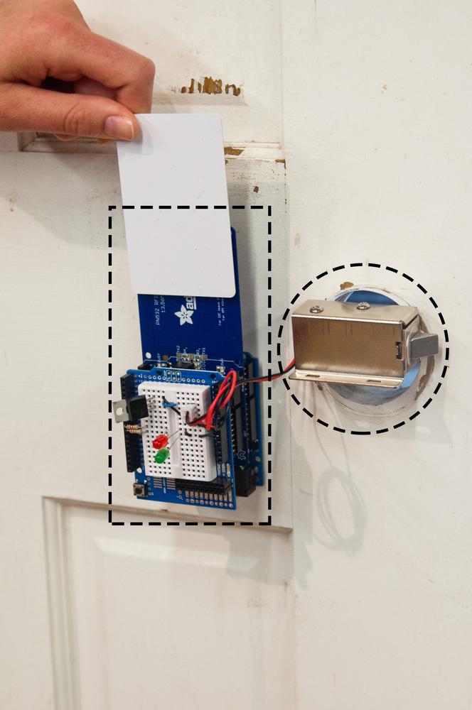
The index.html file for this application is fairly simple. There’s a form with the fields you need to enter: name, room number, number of days you’re staying. The check-in time is calculated automatically by a script in the document head, and filled into a hidden field in the form. You can see the browser view in Figure 7-11. Here is the HTML:
<!DOCTYPE html><html><head><scripttype="text/javascript">functiontick(){varnow=Date(),clock=document.getElementById("clock"),checkin=document.getElementById("checkin");clock.innerHTML=now.toString();checkin.value=now;}</script></head><bodyonload="setInterval(tick, 1000);"><formaction="/submit"method="post">Name:<inputtype="text"name="name"><br/>Room:<inputtype="text"name="room"><br/>Checkin time:<spanid="clock"></span><br><inputtype="hidden"name="checkin"id="checkin">Number of days:<inputtype="text"name="days"><br/><inputtype="submit"value="submit"></form></body></html>
The Server-Side Code
The server-side JavaScript, index.js, starts by declaring a number of variables. It instantiates the serialport library and the express library, then creates an HTTP server using express to handle the request routes. It opens the serial port using the third token from the command-line invocation (you’ll invoke this from the command line by typing node index.js portname where portname is the path to your serial port—more on that later). The last two variables are for maintaining a local copy of the hotel record and for any incoming messages from the Arduino via the serial port:
varserialport=require("serialport"),// include the serialport librarySerialPort=serialport.SerialPort,// make a local instance of serialexpress=require('express'),// make an instance of expressapp=express(),// start Express frameworkserver=require('http').createServer(app),// start an HTTP serverportName=process.argv[2],// third token of the command linerecord={},// NDEF record to senddeviceMessage="";// messages from the writer device
Next, you’re going to tell express.js that you want to use its body parser middleware. This will make it easy to parse the body of the HTTP requests you get from the page. Following that, you start the server (note that it’s running on port 8080, not the normal port 80 for HTTP servers) and open the serialport, and let the user know on the command line:
// use the bodyParser middleware for express:app.use(express.bodyParser());server.listen(8080);// listen for incoming requests on the serverconsole.log("Listening for new clients on port 8080");varmyPort=newSerialPort(portName,{// open the serial port// look for newline at the end of each data packet:parser:serialport.parsers.readline(" ")});// print the port you're listening on:console.log("opening serial port: "+portName);
The parser invoked in this serial port instantiation allows you to tell the serial port when to generate an event. It’s easiest to read incoming serial data from the serial port if the port generates an event for each incoming line of text, so the parser looks for the newline character,
.
The rest of the program consists of three event handlers: one to handle incoming serial data, and two to handle incoming HTTP requests. The serial data handler looks for a new line of incoming serial data, and if that line contains the term Result:, it copies it to one of the global variables, deviceMessage:
// listen for new serial data:myPort.on('data',function(data){// for debugging, you should see this in the terminal window:if(data.search("Result:")!=-1){deviceMessage=data;}console.log("Received: "+data);});
The next two handlers are functions from express.js for handling HTTP GET and POST requests. The app.get() returns the index.html page for any GET request. So http://localhost.com:8080, http://localhost.com:8080/index.html, http://localhost.com:8080/foo, or anything else you put in the browser will return the index page:
// respond to web GET requests with the index.html page:app.get('/*',function(request,response){response.sendfile(__dirname+'/index.html');});
The form in the index page makes a POST request that’s handled by the final handler, app.post(). There are two parts to this handler. In the first part, you extract the elements from the form and put them into the record variable. The time conversions at the end of this section are done because JavaScript’s Date object handles time in milliseconds, while the Time library for Arduino handles it in seconds, as you saw in the previous Arduino example. Once all the necessary parts of the record are extracted from the form or calculated, the handler sends the record out the serial port:
// take anything that begins with /submit:app.post('/submit',function(request,response){record.name=request.body.name;// get the name from the bodyrecord.room=request.body.room;// get the room number from the bodyvardays=request.body.days;// get the number of days from the bodyvartoday=newDate(request.body.checkin);// get the time from the body// calculate the checkout timeStamp:vardeparture=newDate(today.valueOf()+(days*86400000));// convert to unix time in seconds:record.checkin=Math.round(today.valueOf()/1000);record.checkout=Math.round(departure.valueOf()/1000);// send it out the serial port:myPort.write(JSON.stringify(record)+" ");
The Arduino NFC writer device attached to the serial port needs time to read the data, then write it to a tag before it will respond. So the second part of the app.post() handler is a bit of a hack to account for that. It sends the beginning of an HTTP response, including enough of the HTML page to tell the client what’s going on and to give her a link back to the form. Then it keeps the connection open for three seconds using setTimeout(), waiting for a response from the serial port so that it can include the NFC writer device’s response. If there’s no response in that time, it closes the port:
// write the HTML head back to the browser:response.writeHead(200,{'Content-Type':'text/html'});// send the data:response.write("<p><a href="/">Return to form</a></p>");response.write("Sent the following to the writer device:<br>");response.write(JSON.stringify(record)+"<p>");// wait 3 seconds before closing the connection, so that// you can get a response from the writer:setTimeout(function(){// if you got a response from the writer, send it too:if(deviceMessage!=""){response.write("response from writer device: "+deviceMessage+"<p>");deviceMessage="";}else{response.write("no tag present");}// send the link back to the index and close the link:response.end();},3000);// end of setTimeout()});// end of app.post()
If you were developing a full UI, you might have some client-side JavaScript to receive that JSON string and present it in a more readable way. But for now, this should illustrate the principles.
The full source code can be found on GitHub.
That’s all of the application code. Once you’ve saved the index.js file, you need to import the libraries. To do that, change directories to the application’s directory on the command line if you’re not already there. You should have three files in this directory:
- package.json
- index.html
- index.js
To import the libraries, type:
$ npm installYou should see several lines of response, starting with a series of npm GET requests for the appropriate files, and ending in two compile summaries that look like this:
[email protected] node_modules/express ├── [email protected] ├── [email protected] ├── [email protected] ├── [email protected] ├── [email protected] ├── [email protected] ├── [email protected] ├── [email protected] ├── [email protected]([email protected])├── [email protected]([email protected])└── [email protected]([email protected], [email protected], [email protected], [email protected], ...)[email protected] node_modules/serialport ├── [email protected] ├── [email protected] ├── [email protected] └── [email protected]([email protected])
If you see the words NOT OK, heed them. It means that something has gone wrong, and if you scroll back through the npm responses, you’ll find the problem. The most common errors are not using the latest version of node or npm or the libraries (which you can fix by updating your package.json with the version numbers of the latest), not having a network connection, or an incompatibility with one of the libraries and your operating system. In the latter case, check the issues list or forums for the library in question for solutions.
Node-serialport and OS X
On OS X 10.8.x (Mountain Lion) and beyond, you may have trouble installing node-serialport. You need to install the XCode command line tools. Apple doesn’t make these handy utilities easy to find, but you can download them with a login from the Apple developer site. You should be able to do this with a regular Apple login, and not need a paid developer license.
Once you’ve installed the libraries, there will be a new subdirectory in your application’s directory called node_modules. That’s where the libraries live. Now you’re ready to test the app.
First, make sure you’ve uploaded the tag writer sketch from Writing NDEF in Arduino onto your Arduino using the Arduino IDE. Note the name of your Arduino’s serial port. Then on the command line, type:
$ node index.js portnameFor portname, use the name of your serial port, as you learned in The Arduino Development Environment. You should get a response like this:
Listening for new clients on port 8080
opening serial port: /dev/tty.usbmodem621
Now open a browser to http://localhost:8080 and you should get the page shown in Figure 7-11. When you place a tag on the writer device and enter your information, you should get a return page with something like Figure 7-12.

Conclusion
Now that you’ve finished the UI, you’ve got a hotel registration system built, from check-in to door lock. Congratulations! Here’s a review of all the components:
There are two physical devices, built on Arduino Unos with NFC shields (you probably just recycled the same Uno and shield in your case). The first is an NFC writer that accepts a JSON string serially and writes it to a tag. This device is attached to a laptop or desktop computer, which is running the node application you just wrote. The check-in user interface, provided in the brower by the node application, takes the guest’s name, room number, autogenerated time and date, and the number of days the guest is staying, and generates the JSON string for the writer.
The second physical device is the door lock. When the guest taps a tag to the device, it checks the room number and check-in and checkout times on the tag and the current time to see if it should open the door or not. If all is in order, the solenoid lock on the door opens.
This opens up the possible uses for NFC to a wide range of physical situations. As you can see, the concepts for using NFC on a microcontroller are the same as they are for mobile or desktop contexts. Even though microcontroller programming environments might be more limited than what an operating system affords, they still offer the same basic capabilities: reading and writing tags and interpreting NDEF messages and records. They can also provide the ability to sense and control the physical world in ways a traditional computer or mobile device might not be able to do directly.
Given a wider range of computing devices for NFC applications, you have to consider the strengths and limitations of each, and choose your tools appropriately. For example, while the microcontroller was a good choice for the door lock in this application, you could have done the registration application entirely with a tablet device, or with a USB-based NFC reader that you’ll see later on. When you do need to build a custom physical interface, you should determine the minimum physical interaction necessary and try to design and program your device for maximum responsiveness and clarity in the given situation. Small details like limiting your use of blocking functions and providing LED feedback for every physical event make a big difference in the perceived reliability of the device.
In the next chapter, you’ll move beyond simply reading and writing tags into a feature that really differentiates NFC from RFID: peer-to-peer communication between devices.