
7
Programming External Push Buttons, Buzzers, and Stepper Motors
In the previous chapter, we worked with LEDs, seven segments, and their related components, observing them with the help of examples.
This chapter will explore using components such as switches, buzzers, and motors. We will explore their working principles and applications using the MicroPython programs and the Micro:bit. After completing this chapter, you will know how to use the following components:
- Push buttons
- Slide switches
- Buzzers
- Stepper motors
Let us get started by learning how to program these components.
Technical requirements
For this chapter, we will need the following hardware products:
- Push buttons
- LEDs
- A buzzer
- A stepper motor 28BYJ-48 and driver board (ULN2003A)
Push buttons
Push buttons are commonly used in switching operations. Electrical buttons are used in any electronics circuit when switching (on/off) functions need to be performed. Let us consider a scenario where an electrical bulb needs to be turned on or off; we usually go to a switchboard and press the button. It changes the state by moving to an open circuit. This can be done through the Micro:bit. The advantage it offers is that it can be controlled through the program.
The basic principle behind push buttons is to control the current’s flow through pushing or pressing motions. A switch is considered on when it allows the flow of the current, so the circuit will be closed. In the off state, it breaks the current’s flow, so the circuit will be open. There are various types of switches, as shown in Figure 7.1:

Figure 7.1 – Various types of switches – (A) push button, (B) slide switch, (C) DIP DPST switch, and (D) DIP SPST switch x 4
The buttons mentioned in Figure 7.1 can be used for various activities, as follows:
- Push button: To turn a single component attached to the system on and off.
- Slide switch: It has three terminals – the central pin is connected to the ground (GND), whereas the two side terminals are connected to two devices. It can control two components.
- Dual In-Line Package (DIP) Double Pole Single Throw (DPST) switch: The DIP specifies how a switch is grouped, as shown in Figure 7.1 (C) and Figure 7.1 (D). DPST can separate power and ground and has an application in central power units. Here, poles refer to the number of connections in a switch. Throw refers to the position. Single throw means the position. Hence, DSPT allows you to throw two connections in the on and off state together.
- DIP Single Pole Single Throw (SPST): DIP SPST is like DPST but with the difference being the number of devices in the input and output terminals. An SPST switch can only relate to one input and can only provide one output. As shown in Figure 7.1 (D), the four SPST switches are formed in DIPs, which is why DIP SPST switch x 4 has been specified. In xN, N represents the number of switches available in a DIP.
Now that we’ve looked at the different types of switches, let us explore how to use them with the Micro:bit. We explored built-in push buttons in detail in Chapter 5, Built-in LED Matrix Display and Push Buttons. We’ll revise their usage in this section. As shown in Figure 7.2, the two circles represent the push buttons that come built-in with the Micro:bit. These buttons are named A (on the left-hand side) and B (on the right-hand side) on the board. For programming purposes, we will use A and B as the names of the buttons:

Figure 7.2 – Two push buttons on the Micro:bit
To program these buttons, we need to recognize the push operation. The following program has three main steps, which include initialization, loop formation, and providing the logic:
from microbit import *
display.clear()
while True:
    if button_a.is_pressed(): #returns true or false
        display.show(Image.GHOST)
    elif button_b.is_pressed():#returns true or false
            display.show(Image.SKULL)
In the preceding program, after importing the libraries, display.clear() will clear any content on the LED panel. In the while loop, the conditions of buttons A and B are mentioned. display.show() will show a ghost image when button A is pressed, and a skull image will appear when button B is pressed.
Connecting an external push button
To understand the usefulness of the external push button, let us look at an example. We would like to connect and control an LED’s on/off state using an external push button. To do so, we need a push button and an LED connected to the Micro:bit, as shown in Figure 7.3. Here, we can see that a push button is a four-legged device representing two pins as GND and two pins for connecting a device:

Figure 7.3 – Connecting a push button and its output via a push operation
We don’t need to differentiate between the four pins in a push button since they are provided to a static connection. This is because they are most commonly used in Printed Circuit Boards (PCBs) for reset and power-on operations. One push button can control many devices. Once connected to GND and pin 0, the push button connection is made. Now, we need to connect an LED to another pin of the Micro:bit. As shown in Figure 7.3, it is connected to pin 1. The following program will enable the read pin and write pins based on the status of the button state – that is, on or off:
from microbit import *
while True:
    if pin0.read_digital():
        pin1.write_digital(1)
        sleep(1000)
    else:
        pin1.write_digital(0)
        sleep(500)
To implement this functionality, we need to write a program. In this example program, the if-else condition has been provided, which makes the circuit work on both True and False states. pin0.read_digital(): is a pin connected to the button, which indicates that if the switch is pressed, then the LED connected to pin 1 should be on. If the push button is not pressed, pin1.write_digital(0) will turn the LED off. With the help of code, a user can connect the push button and the LED to various pins of the Micro:bit board by simply replacing the pin’s number.
In this section, we learned how to use push buttons using the Micro:bit. We observed the working principles, classifications, and applications of switches. We also learned how to interface the push button with the help of a circuit diagram and program. In the next section, we will learn how to use slide switches.
Slide switches
A slide switch has three terminals and can be used to control two components. It is a type of SPST with two states where external devices can be connected. Its applications include two-way switching, home appliance control, office power control, and others. The functioning of the slide switch can be understood with the help of Figure 7.4:

Figure 7.4 – Connecting two LEDs and a slide switch with the Micro:bit
In Figure 7.4, a slide switch is connected to pin 2 with GND and VCC connections. To observe its working, we have connected two LEDs to pins 0 and 1. The important thing to observe here is that two resistors are also connected to the LEDs. These resistors help control the voltage level of LEDs so that their voltage and current levels don’t vary.
In the following program, we are controlling two LEDs with one switch. Here, we need to assign the LED connections and the switch connection. The rest will be based on the position of the slide switch; it will turn on one LED at a time:
from microbit import *
while True:
    if pin2.read_digital():
        pin0.write_digital(1)
        pin1.write_digital(0)
        sleep(1000)
    else:
        pin1.write_digital(1)
        pin0.write_digital(0)
        sleep(1000)
The preceding program has pin1.write_digital() and pin0.write_digital() to control the on and off states of both LEDs, where 1 is for on and 0 is for off, respectively. The program works almost the same as it did in the case of one switch and one LED, except that in this case, two LEDs are connected, and the same is reflected in the program.
Counting how many times a button is pushed
The good thing about a programable switch is that we can not only control the on-off state but also operate based on the number of times a button is pressed. In the following program, a push button is being used and a counter has been set to count the number of times a push button switch is pressed:
from microbit import *
counter = 0
display.show(counter)
while True:
    if pin0.read_digital():
        counter = counter + 1
        display.show(counter)
        pin1.write_digital(1)
        sleep(1000)
    else:
        pin1.write_digital(0)
        sleep(1000)
In the preceding program, we can see that the counter variable has been assigned an initial value of 0. In the while loop, a switch connected to pin 0, as shown in Figure 7.4 is connected, and its state is being monitored through if-else statements. The counter shows the count, which is initially set to zero. On every press, the counting will start with an increment of +1:

Figure 7.5 – Illustrating the results of counting the number of times a button is pressed
This can be observed in Figure 7.5, which shows that after every press, the LED display is incremented by one. On the coding side, we need to assign a counter and some logic. The counter will help in measuring the number of times the button is pressed. The counter will be part of the logic, as shown in the form of an if-else condition:
from microbit import *
counter = 10
display.show(counter)
while True:
    if pin0.read_digital():
        counter = counter - 1
        display.show(counter)
        pin1.write_digital(1)
        sleep(1000)
    else:
        pin1.write_digital(0)
        sleep(1000)
The preceding code shows the down count after going through the same hardware configuration on the hardware side and setting the counter to an initial value of 10. In code, we can do the down count by using counter = counter – 1.
Connecting multiple push buttons
If we want to try and make a slightly complex design using multiple push buttons and control the LEDs, we need to make specific changes to the hardware and program:

Figure 7.6 – Controlling multiple switches and LEDs connected to the Micro:bit
Figure 7.6 shows the switches are connected to pins 0, 12, 13, and 14, whereas the LEDs are connected to pins 1, 2, 15, and 16. Keep in mind that all the devices have a common ground connection.
The program logic will be more or less the same as controlling one switch and LED, except that in this case, we have multiple input-output devices. As per our understanding, separate pins are assigned to switches and LEDs. This is where the on and off states will be defined:
from microbit import *
while True:
    if pin0.read_digital():
        pin1.write_digital(1)
        pin2.write_digital(0)
        pin15.write_digital(0)
        pin16.write_digital(0)
        sleep(1000)
    elif pin14.read_digital():
        pin1.write_digital(0)
        pin2.write_digital(1)
        pin15.write_digital(0)
        pin16.write_digital(0)
    elif pin12.read_digital():
        pin1.write_digital(0)
        pin2.write_digital(0)
        pin15.write_digital(1)
        pin16.write_digital(0)
    elif pin13.read_digital():
        pin1.write_digital(0)
        pin2.write_digital(0)
        pin15.write_digital(0)
        pin16.write_digital(1)
In the preceding program, pin0.read_digital():, pin14.read_digital():, pin13.read_digital():, and pin13.read_digital(): are connected to the switch and pin1.write_digital(0), pin2.write_digital(0), pin3.write_digital(0), and pin4.write_digital(0) are write options for the LEDs. In pinN.write_digital( ), the 0 and 1 indicate the on and off states, respectively.
The if-elif conditions will execute the respective part of the code when the condition is true. In this way, we are turning on one LED per switch. For example, in the if pin0.read_digital(): condition, write_digital is set as pin1.write_digital(1), pin2.write_digital(0), pin3.write_digital(0), and pin4.write_digital(0), which indicates that only pin 1 is on and the rest are off for the LEDs.
In this section, we covered the slide switch, counted the number of times a switch is pressed, and observed how to handle multiple input-output devices using the Micro:bit. In the next section, we will cover buzzers and their applications.
Buzzers
A buzzer is a piezoelectric device that generates sound. Buzzers have multiple applications, such as generating an audio signal or acting as alarms and beepers. Figure 7.7 shows a buzzer device with positive and negative signal pins:

Figure 7.7 – A buzzer
In the Micro:bit V2, a speaker is connected to the board, as shown in Figure 7.8. It is connected on the flip side of the LED array. From Figure 7.8, we can see that the speaker/buzzer is connected close to the processor:
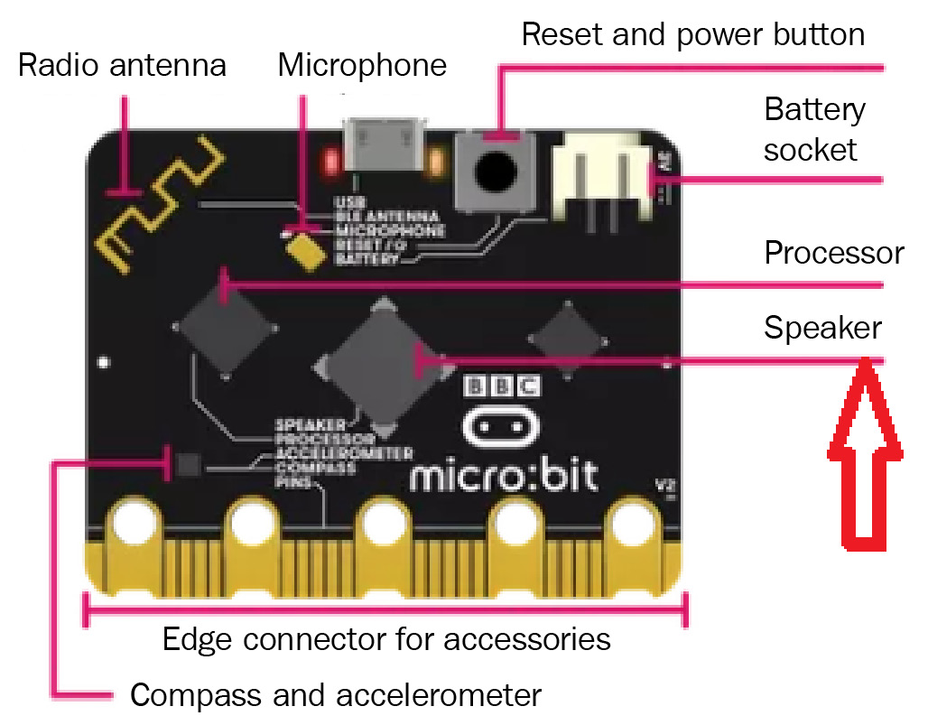
Figure 7.8 – A buzzer on the Micro:bit board (courtesy: https://microbit.org/get-started/user-guide/overview/)
The onboard buzzer can be used directly by executing the following simple program:
import music
music.play(music.ODE)
In the preceding code, the import music module contains predefined tunes that can be used to generate sound. music.play(music.ODE) can play the music through the buzzer:

Figure 7.9 – Connecting an external buzzer to the Micro:bit
The user can also connect an external buzzer to the Micro:bit board. The default pin that’s assigned to connect a buzzer or a speaker is pin 0. As shown in Figure 7.9, the positive pin of the buzzer is connected to GND, while the negative pin is connected to pin 0. Now, let us set the buzzer to play some tunes by simply mentioning them in the following program:
from Micro:bit import *
import music
tune = ["A4:4", "B4:4", "C4:4", "D4:4", "C4:4", "D4:4", "E4:4",  "C4:4", "E4:4", "F4:4", "G4:8", "E4:4", "F4:4", "G4:8"]
music.play(tune)
In the preceding program, a few chords have been mentioned in the tune variable. The chords are evoked through import music, and all the chords mentioned in the tune variable will be played in sequence repetitively.
Let us try to connect a buzzer and switches with the Micro:bit board. To do so, we need three signal pins – that is, pin 0 will be connected to the buzzer, pin 1 will be connected to switch 1, and pin 2 will be connected to switch 2. The ground terminal of all three devices will be connected to the GND pin of the Micro:bit board, as shown in Figure 7.10:

Figure 7.10 – Connecting the switches and a buzzer
Now, we will try to play some audio speech and tunes using a buzzer with the help of our program. First, we need to import the speech and music libraries:
from microbit import *
import music
import speech
while True:
    if pin2.read_digital() == 1:
        music.play("A2:5")
        speech.say("Hello Abhishek")
    elif pin1.read_digital() == 1:
        music.play("E1:7")
        speech.say("MicrooooooooooooooooPython")
    else:
        pass
In the preceding program, we can see that two libraries are being used: import music and import speech. In a while loop, pins 1 and 2 are assigned as digital read using read_digital. In the if-elif conditions, switch 1 and switch 2 are selected, and for both selections, different music tones and speech are assigned. The speech functions are evoked through speech.say().
In this section, we looked at a few applications of buzzers using the Micro:bit and played musical tunes to generate speech. We also learned how to use the music and speech libraries. In the next section, we will be using a stepper motor and looking into its applications.
Stepper motors
A stepper motor is the most commonly used motor in line manufacturing production units and industrial applications. It provides precision with angular motion and torque. We will use the 28BYJ-48 stepper motor for this example. This type of motor includes two main components. The stators are magnetic coils that create an electromagnetic field, and the rotor is a metal shaft that rotates based on the electric field generated:

Figure 7.11 – Connecting a stepper motor to the Micro:bit
As shown in Figure 7.11, a Micro:bit board is connected to the stepper motor through a driver. A 9V battery is connected to the driver circuit to produce driving power, and the five pins of the stepper motor are connected to the driver board. As we can see, the stepper motor is connected to the Micro:bit through the driver board. It is important to understand the core functionality of the driver circuit. ULN2003A has a pair of Darlington transistors that help with load management as the stepper motor consumes heavy current values. IN pins are control inputs from the driver board that go through the Micro:bit pins. In Figure 7.11, we are using pins 0, 1, 2, and 14 to control the stepper motor. The programming of the stepper motor includes pin initialization, fixing the start and stop values, and turning on the stators one at a time:
from microbit import *
import random
pins = [pin0, pin1, pin2, pin16]
while True :
    cycle = random.randrange(Start, Stop)
    while True:
        pins[0].write_digital(1)
        pins[1].write_digital(0)
        pins[2].write_digital(0)
        pins[3].write_digital(0)
        sleep(10)
        pins[0].write_digital(0)
        pins[1].write_digital(1)
        pins[2].write_digital(0)
        pins[3].write_digital(0)
        sleep(10)
        pins[0].write_digital(0)
        pins[1].write_digital(0)
        pins[2].write_digital(1)
        pins[3].write_digital(0)
        sleep(10)
        pins[0].write_digital(0)
        pins[1].write_digital(0)
        pins[2].write_digital(0)
        pins[3].write_digital(1)
        sleep(10)
In the preceding program, the rotation has been set to import random and will generate a random number, which will be used to perform a rotatory operation. The four pins connected to the Micro:bit are enabled in one-at-a-time mode at a given time step and will be controlled.
In this section, we learned about hardware connections and programming a stepper motor to control its rotatory motions. By changing the start and stop values, users can observe the change in the motions. Apart from that, users can also control the speed and angle of the stepper motor.
Summary
In this chapter, we explored the different types of external buttons that are available and their functions. First, we learned how to combine switches with devices such as LEDs. Then, we learned how to combine a buzzer with a switch. We also explored the motor driver circuit and the stepper motor. Finally, we explored commonly used libraries such as music, speech, and random.
In the next chapter, we will investigate the filesystem of the Micro:bit using MicroPython and its applications, such as file handling methods, OS modules, and MicroFS modules.
Further reading
You can find out more about buzzers, switches, and motor drivers for the Micro:bit’s implementation of MicroPython at https://microbit-micropython.readthedocs.io/en/latest/tutorials/buttons.html, https://microbit-micropython.readthedocs.io/en/latest/speech.html, and https://microbit-micropython.readthedocs.io/en/latest/music.html, respectively.