
12
Utility Modeling Tool Belt for Everyday Use
In the previous two chapters, we had an opportunity to unwrap all of the roadway modeling-focused tools available to us within Civil 3D, while also learning some very practical applications of how we can utilize them to further progress on our residential subdivision design. Not only did we learn how to use these particular tools to create design objects within Civil 3D, but we also continued to understand how best to manage these objects and the significance each one provides to the overall design.
In this chapter, we’ll start off by combining and refining our proposed Surface model a little more by utilizing our surface analysis tools and utilize our land development tool belt to ensure that we have proper site drainage throughout our residential subdivision design. Once we are able to locate high and low elevations throughout our residential subdivision design, we’ll then be able to properly locate our storm drainage inlets.
After our storm drainage design is complete, we can then jump into our sanitary sewer and domestic water main design that we’ll tie into systems along York County Highway and will service our entire residential subdivision design. That said, in this chapter, we’ll be covering the following topics:
- Refining proposed Surface models to accommodate proper site drainage
- Creating and modifying storm drainage pipe networks
- Creating and modifying sanitary sewer pipe networks
- Creating and modifying pressure networks
With that, let’s go ahead and open up Civil 3D, or go to your start screen if already open, and create a new drawing using similar steps outlined in Chapter 7, Alignments - The Second Foundational Component to Designs within Civil 3D. We can use our Company Template File.dwt file located in Practical Autodesk Civil 3D 2023Chapter 12 and select Open in the lower right-hand corner of the Select Template dialog box. Once our new file is created, we’ll want to save it as our Utility Model.dwg file to our Practical Autodesk Civil 3D 2023Chapter 12Model location.
As discussed back in Chapter 3, Sharing Data within Civil 3D, model files are intended to contain Civil 3D-modeled objects (both existing conditions and proposed design objects) that are broken out by the type of design objects contained within. Model files will also data reference design data from other model files and external reference files as overlays. Gravity and pressure-based utility network models are able to be data referenced across multiple files, and therefore should be created within our Utility Model.dwg file.
With that, let’s go ahead and attach our Survey Model.dwg file as an overlay, contained within our Practical Autodesk Civil 3D 2023Chapter 12Model location, as well as our Site Plan Reference.dwg file as an overlay, contained within our Practical Autodesk Civil 3D 2023Chapter 12Reference location. Then, we’ll want to jump back into our Prospector tab in our toolspace, and then set the Working Folder type of our Data Shortcuts project to the Practical Autodesk Civil 3D 2023Chapter 12 location and select the C3D_2023_123456_Data_Shortcuts project, as shown in Figure 12.1:

Figure 12.1 – Associate Project to Current Drawing
After our Civil 3D data shortcuts project has been associated with our current file, we can then safely create data references of SRF - Proposed Grade - Residential Subdivision and SRF - Existing Grade – FromSurveyPoints Surface models, along with our Existing Sanitary Sewer, Existing Storm Drainage, Existing Water gravity and pressure networks in our current Utility Model.dwg file.
To do this, we need to expand our Alignments category and our Proposed Conditions folder, right-click on each object (shown in Figure 12.2) and select the Create Reference… option for each:
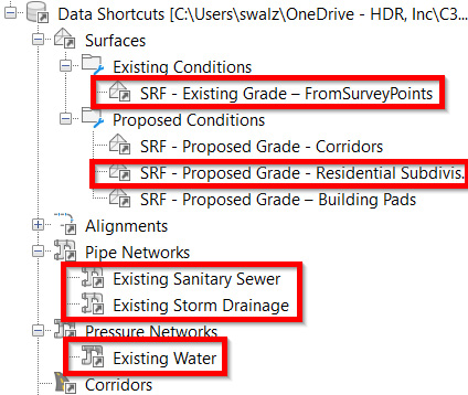
Figure 12.2 – Creating data references of identified Civil 3D objects
Then, with our Utility Model.dwg file set up for us to include all objects we have available to us to represent and reference the existing proposed built environment, we are now ready to continue designing our residential subdivision layout.
Technical requirements
The exercise files for this chapter are available at https://packt.link/UoiPn
Refining proposed Surface models to accommodate proper site drainage
Inside our Utility Model.dwg file, we’ll want to create a new Surface model that will represent our complete proposed built environment. Although we have created a comprehensive SRF - Proposed Grade - Residential Subdivision Surface model that will represent our proposed portion of the built environment, we’ll need to create a new surface that combines both existing and proposed conditions to more clearly understand how our entire residential subdivision design will drain during rain events.
That said, we’ll use the following steps (similar to those defined in previous chapters) to create a full future-built Surface model that we can use to analyze and identify key locations where we’ll need to place inlets and pipes:
- Open up the toolspace from the Home ribbon.
- Navigate to Surfaces within the Prospector tab.
- Right-click and select the Create Surfaces… option.
- In the Create Surfaces dialog box that appears, fill out the fields as follows:
- Once created, we’ll use steps detailed in earlier chapters to paste our existing and then proposed surfaces to the surface definition via Edits.
- Right-click on the SRF - Site Drainage - Residential Subdivision Surface model in Prospector and select the Edit Surface Style… option.
- Navigate to the Analysis tab.
- Expand Elevations.
- Change the Range Color Scheme type to Hydro.
- Click OK.
The final display should look similar to that shown in Figure 12.3. Based on the thematic coloring applied to the default elevation ranges, we know that darker blue areas represent higher elevations within the Surface model, whereas light blue represents lower elevations:

Figure 12.3 – Elevation banding display for SRF - Site Drainage - Residential Subdivision Surface model
With our elevation banding displayed, let’s take a look at our existing storm drainage gravity pipe network. As we select our individual structures, right-click and select Structure Properties…, and we’ll gain access to our Structure Properties dialog box, at which point we’ll want to take note of the invert elevations of the connected pipes to each structure within the Connections tab (refer to Figure 12.4):

Figure 12.4 – Structure Properties dialog box pipe connection details
After checking the inverts of connected pipes of several of our structures, we can quickly determine that the flow of the entire existing storm drainage gravity network is flowing from south to north along York Highway, with the lowest and most logical structure to tie in being at Structure - (10), which contains an Invert Out Pipe connection at an elevation of 739.65', as shown in Figure 12.5:

Figure 12.5 – Lowest invert out at Structure - (10)
Taking note of the invert-out elevation of 739.65', we can make an attempt to drain our site above 741.00' (adding almost 1.5') to ensure that we have enough slope for stormwater to drain through our proposed storm drainage gravity network where possible.
The remainder of our site that falls below the 741.00' elevation will need to drain to a detention pond that will hold water during rain events to contain and then slowly release downstream in an effort to decrease erosion and improve water quality (refer to local guidelines and requirements while designing these).
With that, let’s go back to our SRF - Site Drainage - Residential Subdivision Surface model and adjust the thematic elevation mapping that is currently being displayed so that we can clearly understand where the 741.00' delineation runs through our site.
Let’s select our SRF - Site Drainage - Residential Subdivision Surface model (either in Model Space or in our Prospector), right-click on our mouse, and go to the Surface Properties… option. Once our Surface Properties dialog box appears, we’ll jump over to our Analysis tab and make the following selections (also shown in Figure 12.6), and then click on the OK button:
- Analysis type: Elevations
- Number of ranges: 2
- ID 1 Minimum Elevation: 671.78'
- ID 1 Maximum Elevation: 741.00'
- ID 2 Minimum Elevation: 741.00'
- ID 2 Maximum Elevation: 794.00'
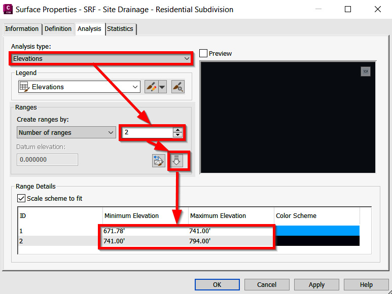
Figure 12.6 – Adjusting surface property elevation banding values
With our updated thematic mapping displaying, let’s make two more adjustments to the SRF - Site Drainage - Residential Subdivision Surface model so that we can quickly determine the surface areas within each of the elevation ranges that we’ll need to drain during storm events.
To do so, let’s create a quick polyline boundary line around the entire extent of the residential subdivision and then apply an outer boundary to our SRF - Site Drainage - Residential Subdivision Surface model, as shown in Figure 12.7:

Figure 12.7 – Applying boundary to SRF - Site Drainage - Residential Subdivision Surface model
Next, we’ll select our SRF - Site Drainage - Residential Subdivision Surface model, right-click with our mouse, and select the Surface Properties… option. Jumping back over to the Analysis tab, we’ll make the following adjustments (also displayed in Figure 12.8):
- Analysis type: User-defined contours
- Ranges | Number: 1
- ID 1 Elevation: 741.00'
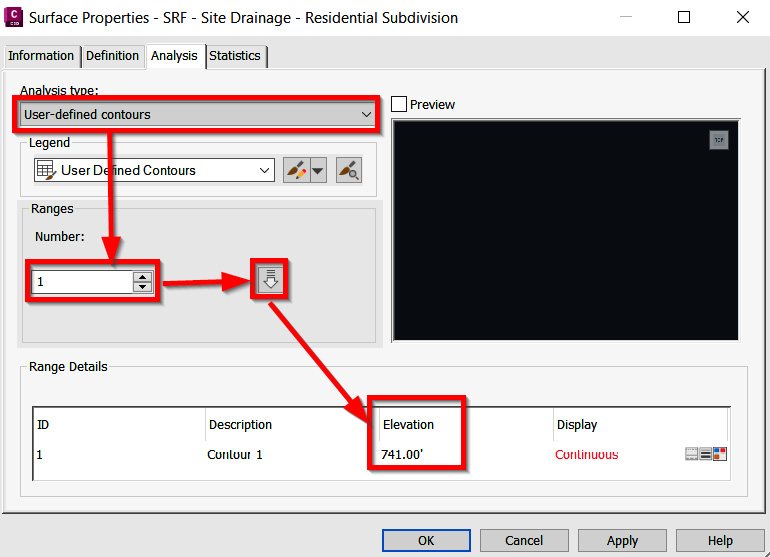
Figure 12.8 – Applying user-defined contour analysis to surface
Then, we’ll hop over to the Information tab and make the following selections (as shown in Figure 12.9):
- Switch to the Information tab within the Surface Properties dialog box.
- Create a new surface style, if one doesn’t already exist, and call it User-Contour Only.
- In the Edit Surface Style dialog box, we’ll switch over to the Display tab.
- Turn on only the User Contours option in the Plan View Direction.
- Click OK, with the final display appearing similar to that shown in Figure 12.9:

Figure 12.9 – Applying user-defined contour display style to surface
Now, we are able to use the Extract Objects from Surface tool to extract the user-defined contours from the surface.
We’ll then use the extracted user-defined contours, our residential subdivision site boundary, along with new polylines that will need to be created using basic AutoCAD tools to determine pervious versus impervious areas versus disturbed areas versus total areas throughout our site to determine catchment areas, inlet locations, and the best route for our proposed storm drainage design.
This combination of linework can be utilized later on by the design engineer to further analyze surface conditions for storm drainage purposes. Without getting into the weeds on the engineering aspects, let’s focus on the actual gravity network design itself, supporting both storm drainage and sanitary sewer systems.
In the next section, we’ll do just that and begin laying out our design networks accordingly.
Creating and modifying storm drainage pipe networks
After running through several calculations and ensuring that we’re adhering to local and state design requirements and regulations, we’ve been able to determine that we’ll need a detention pond with an approximate storage of 22,700 cubic feet, and it will need to be located near the lowest point of our site, which ends up being in the southwestern-most lot within our residential subdivision design, as shown in Figure 12.10:

Figure 12.10 – Location of the detention pond
Let’s go ahead and jump into our Grading Model.dwg file to include this new Detention Pond as a standalone surface and then paste it into our comprehensive SRF - Proposed Grade - Residential Subdivision Surface model. Using our land development tool belt, we’ll want to create a new site for this detention pond.
Feel free to create a boundary polyline that delineates the top of the pond and convert it to a feature line using the Create Feature Lines from Object tool we reviewed in Chapter 9, Land Development Tool Belt for Everyday Use. We can achieve this with the accompanying Feature Lines, Grading Group, and Grading objects, for ultimate inclusion into our overall SRF - Proposed Grade - Residential Subdivision Surface model.
Please keep in mind that this process can be quite iterative to ensure that we are creating a pond that will allow us to store approximately 22,700 cubic feet per design requirements.
With these elements, we can determine invert elevations of pipes associated with our proposed storm drainage gravity network, with the final grading model potentially looking similar to that shown in Figure 12.11 (depending on the Top of Pond feature line you started with):

Figure 12.11 – Graded detention pond
Jumping back into our jump into our Utility Model.dwg file, go ahead and sync your data shortcuts to ensure that we are referencing the most recent SRF - Proposed Grade - Residential Subdivision Surface model so that we can begin laying out our proposed storm drainage network.
With that, let’s go ahead and begin familiarizing ourselves with the gravity network design tools that Civil 3D has available. Fortunately for us, the Civil 3D template that we’ve been using already includes a lot of the standard pipes and structures available out of the box. We’ll begin using the out-of-the-box parts available and review how to create new customized parts lists in the final section of this chapter.
Jumping up to our Home ribbon and navigating over to the Create Design panel, we’ll notice a down arrow next to Pipe Network. If we select the down arrow, we have several ways we can generate both gravity and pressurized utility networks available to us, as displayed in Figure 12.12.
Running from top to bottom, we have the following tools:
- Pipe Network Creation Tools: Allows us to manually create gravity utility networks throughout our site
- Create Pipe Network from Object: Allows us to convert AutoCAD lines, arcs, polylines, and feature lines to a gravity utility network
- Pressure Network Creation Tools: Allows us to manually create pressurized utility pipe networks throughout our site
- Create Pressure Network from Object: Allows us to convert AutoCAD lines, arcs, polylines, and feature lines to a pressurized utility network
- Create Pressure Network from Industry Model: Allows us to convert water industry models to a pressurized utility network:

Figure 12.12 – Pipe Network tools
With that, let’s go ahead and activate the Pipe Network Creation Tools option to pull up our Create Pipe Network dialog box. In the Create Pipe Network dialog box, we’ll go ahead and fill out the fields and make selections as follows (also shown in Figure 12.13), and then select the OK button at the bottom of the dialog box:
- Network name: GPN - Proposed Storm Drainage - York Hwy
- Network description: Proposed Storm Drainage Network that will tie-into York Hwy Existing Drainage Network and our Proposed Detention Pond
- Network parts list: Storm Sewer
- Surface name: SRF - Proposed Grade - Residential Subdivision
- Structure label style: Data with Connected Pipes (Storm)
- Pipe label style: Length Description and Slope

Figure 12.13 – Create Pipe Network dialog box
After selecting the OK button in the Create Pipe Network dialog box, we’ll be presented with our Network Layout Tools toolbar, which will provide us with access to many of the necessary gravity utility network design tools that Civil 3D has available. Running from left to right, we have the following tools available to us (also shown in Figure 12.14):
- Pipe Network Properties: Allows us to access the Pipe Network Properties dialog box where we can specify various settings and styles to be applied to our gravity utility network being designed.
- Select Surface: Allows us to specify a surface that we intend to reference and target as we lay out our proposed gravity utility network.
- Select Alignment: Allows us to specify an alignment already created, or available, in our current file. Alignment referencing can help with staking purposes where we can quickly identify the station and offset positioning.
- Parts List: Allows us to specify a parts list that contains a predefined set of structures and pipes.
- Structure List: Allows us to specify the type of structure we’d like to place in our files as we lay out our gravity utility network.
- Pipe List: Allows us to specify the type of pipe we’d like to place in our files as we lay out our gravity utility network.
- Structure Connection and Pipe Insertion Points: Allows us to change the placement and insertion points of structures and connected points as we lay out our gravity utility network.
- Toggle Upslope/Downslope: Allows us to change the flow direction of our gravity utility network.
- Delete Pipe Network Object: Allows us to remove a structure and/or pipe from our gravity utility network being designed.
- Draw Pipes and Structures: Allows us to design our gravity utility network as pipes only, structures only, or pipes and structures all at once.
- Pipe Network Vistas: Allows us to pull up the Panorama where we can make modifications to structures and/or pipes of the gravity utility network being designed.
- Undo: Allows us to undo previous insertion points of structures and/or pipes:

Figure 12.14 – Create Pipe Network dialog box
Note
The Network Layout Tools toolbar has a tendency to close out if users accidentally hit the Esc, spacebar, and/or Enter keys on the keyboard. If that does occur, we can always recall the Network Layout Tools toolbar by right-clicking with our mouse on the Network Name field in our Toolspace | Prospector and selecting Edit Network.
For our GPN - Proposed Storm Drainage gravity utility network, we’ll start at the northern side of our residential subdivision design to place inlets and pipes at key locations to divert stormwater into the Existing Storm Drainage gravity utility network along York Hwy.
As we analyze our future graded conditions, we can see where we have ditches alongside our road (beyond the paved surface) in between the curb and gutter and our building pads, and quickly determine where our stormwater is running to.
This will allow us to place our structures and connected pipes along with the placement of our driveway culvert pipes, and also identify locations where we will need to capture additional runoff via diversion ditches/swales.
If at any point you are having some difficulty trying to understand how water is flowing on top of our future graded conditions, Civil 3D has a pretty handy tool called Water Drop. The Water Drop tool will allow us to quickly analyze surface conditions and then draw a construction line indicating the most direct path that stormwater will eventually drain to based on the location we click within our residential subdivision design.
To access the Water Drop command, we can simply select our SRF - Site Drainage - Residential Subdivision Surface model to access our Surface Contextual ribbon along the top of our Civil 3D session. Once visible, navigate to our Analyze ribbon and select the Water Drop tool. Once activated, a Water Drop dialog box will appear, where we’ll want to make the following selections (also displayed in Figure 12.15):
- Path Layer: C-HYDR-CTCH-FPTH
- Path Object Type: 2D Polyline
- Place Marker at Starting Point: Yes
- Start Point Marker Style: Basic

Figure 12.15 – Water Drop dialog box
Tip
If 3D polylines were selected, potentially leverage them to define our time of concentration for stormwater analysis purposes.
After setting these as our Water Drop defaults and clicking OK to exit out of the Water Drop dialog box, we’ll be prompted at our command line to select a point.
As we select points throughout our residential subdivision design, Civil 3D is analyzing Surface model conditions, determining how stormwater will travel, and identifying where it will end up. An example of the output will look similar to that displayed in Figure 12.16:

Figure 12.16 – Water Drop analysis
After completing the northern portion of our GPN - Proposed Storm Drainage gravity utility network that ties into the Existing Storm Drainage gravity utility network along York Hwy, we’ll run through a similar process to drain the remainder of our site to the proposed detention pond in the southwest corner that we designed earlier in this chapter.
You may have noticed that in locations where we are placing our driveway culverts, which are only displayed as pipes, the pipe rules are forcing the pipes to be designed with a minimum of 3’ coverage, and not locating them with an invert elevation at grade.
Applying pipe rules within Civil 3D allows us to validate our gravity utility network designs as we’re laying them out in Model Space. We can specify and set various design parameters that our networks will need to conform to, giving us a higher level of assurance that we are designing in accordance with codes and regulations.
Typically, when I’m laying out my proposed storm drainage designs where driveway culverts are required to properly drain the site, I’ll place them temporarily using the same rules as a typical storm drainage network would be expected to conform to. Once all driveway culverts have been placed in their appropriate locations, I’ll then create a new pipe rule that I will apply to my driveway culverts only.
To do this, we’ll jump over to our Settings tab within our Prospector, navigate down to—and expand—our Pipe category to access our Pipe Rule Sets section. Once there, we’ll right-click with our mouse on Pipe Rule Set and select the New… option, as shown in Figure 12.17:
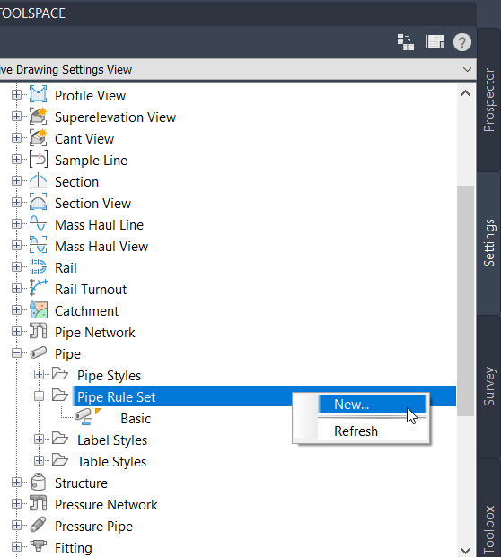
Figure 12.17 – Creating a new pipe ruleset
In the Information tab within the Pipe Rule Set dialog box that appears, we’ll fill in the Name value as Driveway Culverts and Description value as To be applied to Driveway Culvert Pipes with no Structure Connections. Next, we’ll switch over to our Rules tab and use the following steps (shown in Figure 12.18) to create a driveway culvert rule that we’ll use to update our driveway culverts so that the inverts are at grade:
- Select the Add Rule… option within the Pipe Rule Set dialog box.
- Change the Rule name value to Cover Only in the Add Rule dialog box.
- Click OK in the Add Rule dialog box.
- Expand the Cover Only parameter in the Pipe Rule Set dialog box.
- Change the value for Minimum Cover and Maximum Cover to -1.50' within the Pipe Rule Set dialog box, where the 1.50' value actually places the driveway culvert pipes such that 18" diameter pipe inverts are at grade.
- Click OK in the Pipe Rule Set dialog box:

Figure 12.18 – Steps to creating a new pipe rule
With our new driveway culverts pipe rule created, we can go back to our storm drainage design and update the driveway culverts within our GPN - Proposed Storm Drainage gravity utility network.
To update these, we’ll want to select all driveway culvert pipes displayed in our Model Space, then go back up to our Pipe Network Contextual ribbon and select the Split Network option within the Modify panel, as shown in Figure 12.19:

Figure 12.19 – Split Network tool
Once the Split Network tool has been initiated, we’ll be prompted at the command line to either create a new pipe network or select a network. Since we haven’t created a new pipe network to associate our driveway culverts with, we’ll want to select the Create new Pipe Network option, which will then pull up our Create Pipe Network dialog box.
Here, we’ll fill out the available fields and make selections as follows (also displayed in Figure 12.20), and then select OK:
- Network name: GPN - Proposed Driveway Culverts
- Network description: Proposed Storm Drainage Network for Driveway Culverts Only
- Network parts list: Storm Sewer
- Surface name: SRF - Site Drainage - Residential Subdivision
- Structure label style: <none>
- Pipe label style: Length Description and Slope

Figure 12.20 – Create Pipe Network: GPN - Proposed Driveway Culverts
With our driveway culverts now separated into their own gravity utility network, we can quickly assign and then apply our new driveway culverts pipe rule to all pipes to update cover and inverts accordingly.
Jumping back to our Prospector tab in our toolspace, let’s scroll down to—and expand—our Pipe Networks category, expand our GPN - Proposed Driveway Culverts gravity utility network, and then select the Pipes category within.
In the lower portion of our toolspace, we’ll want to select all pipes listed, then, while still holding the Shift key on our keyboard, we’ll click on one of the fields within the Rule Set column where it says Basic.
By selecting the field, we can change our Basic ruleset to the newly created Driveway Culverts ruleset and click OK to apply to all driveway culvert pipes within our GPN - Proposed Driveway Culverts gravity utility network, as shown in Figure 12.21:

Figure 12.21 – Applying the Driveway Culverts ruleset to pipes within the GPN - Proposed Driveway Culverts gravity utility network
With our driveway culvert pipes now reading the new Driveway Culverts ruleset, we can now individually select each pipe within our Model Space to call up our Pipe Network Contextual ribbon again, then select the Modify down arrow in the Modify panel, and select Apply Rules (refer to Figure 12.22):

Figure 12.22 – Applying rules to pipes within the GPN - Proposed Driveway Culverts gravity utility network
At this point, we should be in pretty good shape with our storm drainage gravity utility network design within our residential subdivision. Now, let’s focus on our proposed sanitary sewer network that we’ll tie into our existing sanitary sewer gravity network located along York Hwy.
Creating and modifying sanitary sewer pipe networks
As recognized while analyzing elevations and grades at the beginning of our storm drainage gravity utility network design, we realized that we are approximately 25’ below the existing grade along York County Highway at our lowest point within our residential subdivision design.
That said, we will need to use a combination of gravity and pressurized utility networks and find a suitable location for the placement of a required pump station to ensure that we are able to remove wastewater from our site and tie into the existing sanitary sewer network along York Hwy.
With that, let’s go ahead and create a proposed sanitary sewer network using similar steps used to create our GPN - Proposed Storm Drainage gravity utility network earlier in this chapter.
Using the Pipe Network Creation Tools option as done earlier, we’ll create a new sanitary sewer gravity utility network with the following fields applied (also displayed in Figure 12.23) and then click the OK button:
- Network name: GPN - Proposed Sanitary Sewer
- Network description: Proposed Sanitary Sewer Network that will tie-into Proposed Pump Station
- Network parts list: Sanitary Sewer
- Surface name: SRF - Proposed Grade - Residential Subdivision
- Structure label style: Data with Connected Pipes (Sanitary)
- Pipe label style: Length Description and Slope

Figure 12.23 – Create Pipe Network dialog box
Starting in the cul-de-sac, we’ll begin laying out our GPN - Proposed Sanitary Sewer gravity utility network west through the intersection of our ALG – Subdivision Side Road – Cul-De-Sac and ALG – Subdivision Main Road – Access alignments, and then south toward our southwestern-most lot where we’ll end up placing our pump station.
Once the northern portion of our GPN - Proposed Sanitary Sewer gravity utility network is completely laid out, we’ll then want to work our way from the first lot near the main intersection with York Hwy to the same southwestern-most lot, with the final GPN - Proposed Sanitary Sewer gravity utility network looking similar to that shown in Figure 12.24:

Figure 12.24 – GPN - Proposed Sanitary Sewer gravity utility network
Before moving on to designing a pressurize sanitary sewer force main that will essentially carry wastewater from our pump station into the Existing Sanitary Sewer gravity utility network within York Hwy, we’ll want to perform an interference check between our storm drainage and sanitary sewer gravity utility networks to ensure that we have enough clearance between utility networks.
To access this, we’ll want to go up to our Analyze ribbon and select the Interference Check tool located in the Design panel. Once the Interference Check tool has been activated, we’ll see a Create Interference Check dialog box appear, at which point we can fill out the fields as necessary and define the interference checking criteria by selecting the 3D proximity check criteria… option, as shown in Figure 12.25:

Figure 12.25 – Create Interference Check dialog box
After performing, we will receive a message that will notify us whether we have any interferences. If interferences have been detected, a node, or block, will be placed at the exact location in which there is a conflict that does not meet the 3D Proximity Check Criteria values we had input originally.
If any interferences have been detected, it’s recommended to resolve these by selecting Connected Structures, right-clicking with our mouse in Model Space, selecting the Structure Properties option, and updating the Connected Pipe inverts accordingly.
After all detected interferences have been resolved, we can focus on designing our pressurized systems for our required sanitary sewer force main along with our domestic water main to service all individual properties.
Creating and modifying pressure networks
With the gravity utility network portion of our sanitary sewer designed, let’s begin laying our force main that will carry wastewater from our pump house located in the southwestern-most lot and tie to the Existing Sanitary Sewer main located along York Hwy.
As discussed earlier in the chapter, we’ll want to jump back up to our Create Design panel within our Home ribbon and activate the Pressure Network Creation tools (refer to Figure 12.12).
Once the Pressure Network Creation tools have been activated, we’ll be presented with a Create Pressure Pipe Network dialog box where we’ll want to fill out the fields and make the selections as follows (also shown in Figure 12.26), and then click the OK button:
- Network name: PPN - Proposed Sanitary Sewer
- Network description: Proposed Force Main from Pump Station within Residential Subdivision to tie into Existing Sanitary Sewer Gravity Utility Network along York Hwy
- Pipe Run name: Force Main
- Parts list: Water
- Pipe size: pipe-6 in-push on-ductile iron 350 psi-AWWA C150
- Reference surface: SRF - Proposed Grade - Residential Subdivision
- Create surface profile to follow: Check
- Cover: 3.00'
- Pressure pipe label style: Nominal Diameter and Material
- Fitting label style: Nominal Diameter Bend Angle and Material
- Appurtenance label style: Nominal Diameter Valve Type

Figure 12.26 – Create Pressure Pipe Network dialog box
After all fields and selections have been made and we click the OK button inside of the Create Pressure Pipe Network dialog box, we’ll want to bring our attention to the Pressure Pipe Network Contextual ribbon that will automatically display along the top of our Civil 3D session, as shown in Figure 12.27. Running from left to right, we have the following panels and tools available to us:
- Properties:
- Network Properties: Allows us to modify general, layout, profile, and section properties associated with our pressure pipe network
- Part Properties: Allows us to edit individual parts associated with our pressure pipe network
- Pipe Run:
- Add New Pipe Run: Allows us to create a new pipe run as needed. This tool will be required to begin laying out our design and will also come in handy if there is a need to branch and separate our full pressure pipe network into individual runs later on
- Pressure Pipe Selection: Allows us to select the parts that we would like to apply to our design
- Add Bends Automatically: Allows us to either automatically add bend fittings or have pipes connect directly to each other
- Layout:
- Add Bend/PI: Allows us to insert a bend and/or point of intersection into our design and alignment as needed
- Remove Bend/PI: Allows us to remove a bend and/or point of intersection from our design and alignment as needed
- Add Branch Fitting: Allows us to insert a branch fitting in the event that we need to create a new pipe run
- Add Fitting: Allows us to insert fittings individually based on the part selection directly across from this tool
- Add Appurtenance: Allows us to insert an appurtenance individually based on the part selection directly across from this tool
- Panorama: Allows us to pull up our Panorama to edit pipes, fittings, and appurtenance properties
- Profile:
- Pipe Run Profile: Allows us to create and modify a profile along our pipe run
- Draw Parts in Profile View: Allows us to project parts within our network into a profile view already created within our drawing
- Modify:
- Swap Parts: Allows us to swap parts in the event that we need to change diameter, material, and so on
- Break Pipe Run: Allows us to segment a pipe run as needed
- Merge Pipe Runs: Allows us to merge a pipe run as needed
- Relink Pipe Run: Allows us to relink our pipe run with its corresponding alignment in the event that it has been broken
- Regen Pressure Solids: Regenerates solids displayed for fittings and appurtenances in the event that they are missing
- Connect to Structure: Allows us to connect a pressure pipe to a gravity structure (this will be needed for our force main connection to the GPN - Proposed Sanitary Sewer gravity utility network)
- Analyze:
- Design Check: Allows us to validate our design is in conformance with the defined parameters and tolerances specified
- Depth Check: Allows us to verify that our pressure pipe network meets the minimum depth defined
- Labels & Tables:
- Add Labels: Allows us to add labels associated with our pressure pipe network design
- Add Tables: Allows us to create tables displaying information associated with our pressure pipe network design
- Compass:
- Visibility: Allows us to toggle on/off our design compass that will be displayed as we are laying out our pressure pipe network design
- Snapping: Allows us to toggle on/off the ability to snap to specified bend/fitting angles as we are laying out our pressure pipe network design
- Close: Allows us to close out of the Contextual ribbon:

Figure 12.27 – Pressure Pipe Network contextual ribbon
Note
After initially creating our pressure pipe network, we will be prompted at the command line to specify the first pressure pipe point to begin laying out our design. If you may have accidentally canceled out of this prompt, we’ll need to select the Add New Pipe Run tool within our Pipe Run panel. Once activated, a Create Pipe Run dialog box will appear, at which point we’ll want to fill out fields and make selections similar to those detailed in Figure 12.26.
Let’s go ahead and start laying out our force main pipe run by snapping to the center of our final structure created inside of our pump station for our GPN - Proposed Sanitary Sewer gravity utility network. After snapping to the center and clicking with the left button on our mouse to begin our layout, we’ll run perpendicularly into our wet well right beside the pump station. Next, we’ll then run 90 degrees toward our ALG – Subdivision Main Road – Access alignment and run our force main pipe along the south side of our subdivision main road and tie into the existing sanitary sewer structure at the main entrance of our subdivision.
After our network has been configured, we’ll hop back up to our Pressure Pipe Network Contextual ribbon and select the Connect to Structure tool located within our Modify ribbon pulldown. Once the Connect to Structure tool has been activated, we’ll be prompted at our command line to select a structure from our gravity utility network and a pipe from our pressure utility network to connect to.
We’re going to then make connections at the beginning and end of our overall force main pipe run accordingly, with the final force main design looking similar to that shown in Figure 12.28:

Figure 12.28 – Force main pipe run design
Next, we’ll move into designing our domestic water main. Taking local design requirements into consideration, there will likely be a minimum horizontal and vertical separation that needs to be maintained between other utilities, with an emphasis on sanitary sewer networks.
That said, we’ll need to snake our domestic water main alongside our roads through our residential subdivision design with the tie back into the existing water main along York Hwy.
So, let’s jump back up to our Create Design panel within our Home ribbon and select the Pressure Network Creation tools again and fill out the new Pressure Network dialog box as follows (also displayed in Figure 12.29), and then select the OK button:
- Network name: PPN – Domestic Water Main
- Network description: Proposed Domestic Water Main within Residential Subdivision to tie into Existing Water Pressure Utility Network along York Hwy
- Pipe Run name: Water Main
- Parts list: Water
- Pipe size: pipe-6 in-push on-ductile iron 350 psi-AWWA C150
- Reference surface: SRF - Proposed Grade - Residential Subdivision
- Create surface profile to follow: Check
- Cover: 3.00'
- Pressure pipe label style: Nominal Diameter and Material
- Fitting label style: Nominal Diameter Bend Angle and Material
- Appurtenance label style: Nominal Diameter Valve Type

Figure 12.29 – Create Pressure Pipe Network dialog box
After selecting the OK button, let’s go ahead and start laying out our PPN – Domestic Water Main pressure utility network, starting at the tie-in connection point of our Existing Water pressure utility network along York Hwy.
We’ll start by snapping to a point along the centerline of the Existing Water pressure utility network along York Hwy and work our way through our residential subdivision to the cul-de-sac. After completion, we’ll zoom back to our connection point to the Existing Water pressure utility network along York Hwy to add a connecting tee.
To do this, let’s go back up to our Pressure Network Contextual ribbon, change our Fitting Selection value to tee-12 in x 6 in- push on-ductile iron–350 psi-AWWA C111/C153, and select the Add Fitting option within our Layout panel, as shown in Figure 12.30:

Figure 12.30 – Adding fitting only to the pressure network
After finalizing this connection point, we should end up with a domestic water main design looking similar to that displayed in Figure 12.31:

Figure 12.31 – Final display of our domestic water main pressure network
At this point, if we were to select our pressure networks and our surface to view in Object Viewer, we’d quickly notice that although the endpoints of our pipes, along with our fittings, are located underneath our surface, there are still many locations along the length of our pipes that are above our surface. To update, we’ll want to leverage our profile views to segment these long runs and push our pipes below the surface and ensure that we have enough coverage.
To do this, we’ll start by selecting our PPN – Domestic Water Main pressure pipe network, either in Model Space or in Toolspace, and select Edit Pressure Network. With our Pressure Pipe Network contextual ribbon activated, let’s select the Pipe Run Profile tool within our Profile panel, as shown in Figure 12.32:

Figure 12.32 – Pipe Run Profile tool
Once the Pipe Run Profile tool has been activated, a Pipe Run Profile Settings dialog box will appear. In this dialog box, we’ll want to fill out fields and make selections as follows (also displayed in Figure 12.33), and then click the Enter button at the bottom of the dialog box:
- Offset Style: Cut Length
- Reference Profile: SRF - Proposed Grade - Residential Subdivision Surface
- Offset Distance: 3.00'
- Update Dynamically: Check the box
- Draw Profile in: New Profile View
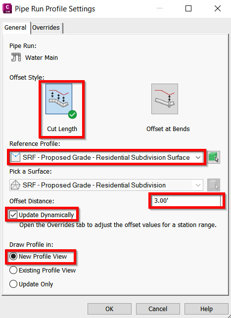
Figure 12.33 – Pipe Run Profile Settings dialog box
After selecting OK, a Create Profile View dialog box will appear. Since this is only a temporary profile view that we’re creating at this point in time to simply segment our pressure pipes and push down to a consistent depth below our SRF - Proposed Grade - Residential Subdivision Surface model, we’ll simply just select the Create Profile View option along the bottom of our Create Profile View dialog box without filling out any additional criteria. We’ll then be prompted to select Profile View Origin at the command line. Once our origin has been defined, we should have a profile view looking similar to that shown in Figure 12.34:
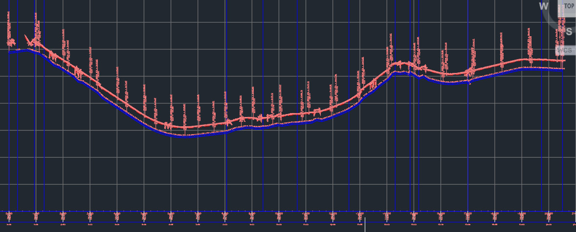
Figure 12.34 – Pipe Run profile view
As shown in Figure 12.34, we have successfully segmented our pipes and now have a consistent 3.00' coverage applied throughout the entire run of our PPN - Domestic Water Main pressure pipe network. Using the same steps, we want to run through the process for our PPN - Proposed Sanitary Sewer pressure pipe network as well.
With the final pieces to our residential subdivision design in place, we can begin exploring different ways we can analyze our design, with the end goal of producing a comprehensive plan set that we are confident conforms to all design standards and requirements necessary.
Summary
As we worked through this chapter, we have been able to make significant progress toward shoring up our utility design throughout our residential subdivision. We’ve learned the many aspects of utility design as it relates to both gravity and pressure utility networks.
We were able to perform several modifications and checked our designs against various design requirements and parameters. We even learned how to tie our proposed utility networks into existing networks, as well as tie gravity and pressure utility networks into each other.
In our next chapter, we’ll take a look at sectioning capabilities and tools available to us within Civil 3D, where we can further analyze the residential subdivision grading, roadway, and utility designs that we’ve developed thus far. This will be the final form of analysis that we’ll be covering before jumping into plan production, sheet creation, and extended capabilities available to us to increase efficiencies along the way.