
8
Profiles - The Third Foundational Component to Designs within Civil 3D
As discussed in the past few chapters, surfaces, alignments, and profiles are often considered to be the three major foundational components required to build a true civil infrastructure design model within Civil 3D. In Chapter 6, Surfaces - The First Foundational Component to Designs within Civil 3D, we took a deep dive into surfaces, while in Chapter 7, Alignments - The Second Foundational Component to Designs within Civil 3D, we took a deep dive into alignments.
Along the way, we’ve learned several ways to generate, modify, and analyze both surface models and alignment geometry. We realized towards the end of Chapter 7 that from an analysis standpoint, we fall slightly short with some of the functionality available to us, as we have yet to generate profiles that tie the Surfaces and Alignments together.
In this chapter, we’ll take a deep dive into the world of profiles, where we’ll begin to realize how key this particular component is to establish the foundation for our Residential Subdivision design. Once our profiles are created, we’ll also revisit some of the missing analysis capabilities that we were unable to perform in Chapter 6, Surfaces - The First Foundational Component to Designs within Civil 3D as they are related to alignments.
With that in mind, in this chapter, we’ll focus on the following key aspects as they relate to profiles in Civil 3D:
- Understanding ways to create a profile
- Setting up our profile views
- Creating design profiles
- Understanding profiles and profile view styles
- Further analyzing profile and alignment geometry
As previously discovered with surfaces and alignments, we have begun to realize how these modeled objects play a big part in setting the foundation for our design. With profiles being the missing link to tie all these types of objects together, let’s not waste any more time and jump right into it.
Let’s go ahead and open up Civil 3D, or go to the Start screen if already open, and create a new drawing using similar steps to those outlined in Chapter 7, Alignments - The Second Foundational Component to Designs within Civil 3D. We can use the Company Template File.dwt file located in Practical Autodesk Civil 3D 2024Chapter 8 and select Open in the lower right-hand corner of the Select Template dialog box.
Once our new file is created, we’ll want to save it as the Grading Model.dwg file to the Practical Autodesk Civil 3D 2024Chapter 8Model location.
As discussed back in Chapter 3, Sharing Data within Civil 3D roadway centerline alignments and their profiles are often used to create corridor objects, which will ultimately generate our proposed surface model (or at least a portion of it). Therefore, we will need the grading model to contain the profiles that will display the existing and proposed vertical geometry.
Next, we want to attach the Survey Model.dwg and Alignment Model.dwg files as an overlay, all contained within the Practical Autodesk Civil 3D 2024Chapter 8Model location. Then we want to jump back into the Prospector tab in TOOLSPACE, and then update the Working Folder field of the Data Shortcuts project to the Practical Autodesk Civil 3D 2024Chapter 8 location and select the C3D_2024_123456_Data_Shortcuts project, as shown in Figure 8.1.

Figure 8.1 – Associate Project to Current Drawing
After our Civil 3D Data Shortcuts project has been associated with the current file, we can then safely create the data references for the SRF – Existing Grade – FromSurveyPoints surface model, along with the ALG – Existing York Hwy – FromSurveyPoints, ALG - Subdivision Main Road - Access, and ALG - Subdivision Side Road - Cul-De-Sac alignments and add them to our current Grading Model.dwg file.
To do this, we need to expand our surfaces and alignments categories and the Existing Conditions folders by right-clicking on each element, as shown in Figure 8.2) and selecting the Create Reference option for each.

Figure 8.2 – Create data references for identified Civil 3D objects
Then, with the Grading Model.dwg file set up for us to include all elements we have available to us to represent and reference the existing built environment, along with the beginnings of the future built environment, we are now ready to begin designing our residential subdivision layout.
Technical requirements
The exercise files for this chapter are available at https://packt.link/UoiPn
Understanding the ways to create a profile
In this section, we’ll begin exploring multiple ways to create a profile, all while getting a full understanding of the various profile creation tools available to us within the Civil 3D environment.
To access our profile creation tools, we need to activate the Home ribbon along the top of our Civil 3D session, go to the Create Design panel, and click on the down arrow next to where it says Profile.

Figure 8.3 – Profile creation tools
As shown in Figure 8.3, we have the following profile creation tools available to us:
- Create Surface Profile: This allows us to create a profile referencing an alignment and surface model existing in the current file
- Profile Creation Tools: This allows us to create vertical geometry (also known as a profile) along an existing horizontal alignment (a profile view must already be created within the current file)
- Create Best Fit Profile: This allows us to create optimal vertical geometry (a profile) along an existing horizontal alignment based on various parameters identified (a profile view must already be created within the current file)
- Create Profile from File: This allows us to create a profile by importing an ASCII survey point file
- Quick Profile: Allows us to create a temporary profile and profile view using various 2D and 3D objects, including 2D/3D polylines, feature lines, and points
- Create Superimposed Profile: Allows us to project profiles into other profile views
- Create Profile from Corridor: Allows us to create a profile from a feature line generated/extracted from a corridor model
Let’s now go ahead and create the first profile for the ALG - Subdivision Main Road – Access alignment. To do so, we need to use the Create Surface Profile command (refer to Figure 8.3 for the location of this tool).
Once the Create Profile from Surface dialog box has been activated, we need to take the following steps to connect the proposed horizontal alignment with the existing surface model, as shown in Figure 8.4:
- In the Alignment field, select the ALG - Subdivision Main Road – Access alignment.
- In the Select Surfaces field, select the SRF – Existing Grade – FromSurveyPoints surface model.
- Once both the alignment and surface have been selected, click on the Add>> button, at which point we will see Profile list populate with the corresponding alignment and surface.
- Click on the OK button to exit.

Figure 8.4 – Create Profile from Surface dialog box
Setting up profile views
Now that we’ve connected the ALG - Subdivision Main Road – Access alignment to the SRF – Existing Grade – FromSurveyPoints surface model, we can now create the profile view in preparation for developing the proposed grading model.
By going back to the Home ribbon and then proceeding to the Profile and Section Views panels, we can access our profile view tools. If we click on the down arrow next to where it says Profile View, we’ll see a drop-down menu appear with the following options, shown in Figure 8.5:
- Create Profile View: This allows us to create a singular profile view along with an alignment
- Create Multiple Profile Views: This allows us to create multiple profile views in the event that a particular alignment is long (typically used for sheeting purposes)
- Project Objects to Profile View: This allows us to project objects into profile views for display and coordination purposes
- Add Crossings to Profile View: This allows us to project linear objects that cross alignments into profile views for display and coordination purposes

Figure 8.5 – Profile View tools
For the time being, we want to select the Create Profile View option. Being that we’re not at the stage of sheeting yet, and only focusing on design, profiles are easier to manage, create, and manipulate when they are all displayed in one continuous profile view.
Once the Create Profile View dialog box appears, we’ll make the following selections and inputs:
- General:
- Select alignment: ALG - Subdivision Main Road - Access
- Profile view name: PRV - Subdivision Main Road - Access
- Description: Profile View along ‘Subdivision Main Road - Access’ Alignment
- Profile view style: Land Desktop Profile View

Figure 8.6 – Create Profile View – General
- Station Range: Automatic

Figure 8.7 – Create Profile View – Station Range
- Profile View Height: Automatic
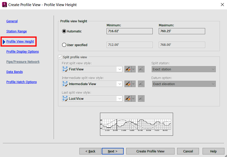
Figure 8.8 – Create Profile View – Profile View Height
- Profile Display Options:
Style: Existing Ground Profile

Figure 8.9 – Create Profile View – Profile Display Options
- Data Bands:
Select band set: EG-FG Elevations and Stations

Figure 8.10 – Create Profile View – Data Bands
Finally, we select the Create Profile View button in the lower section of the Create Profile View dialog box. Once selected, we’ll be prompted to define a location in which we want to place our new profile view.
Let’s zoom out a little bit so that we can see the full site and left-click the mouse button to place our profile view on the right side of the site, as shown in Figure 8.11.
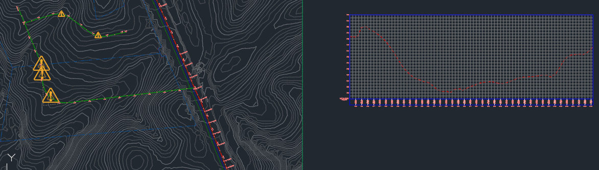
Figure 8.11 – Placing our new profile view
Using the same steps for creating a profile and profile view that we previously went through, let’s go ahead and create another profile view for the ALG - Subdivision Side Road – Cul-De-Sac alignment.
First, create a profile of the existing surface linked to the ALG - Subdivision Side Road-Cul-De-Sac alignment, then use the following criteria in the Create Profile View dialog box (with the final output as shown in Figure 8.12):
- General:
- Select alignment: ALG - Subdivision Side Road – Cul-De-Sac
- Profile view name: PRV - Subdivision Side Road - Cul-De-Sac
- Description: Profile View along ‘Subdivision Side Road - Cul-De-Sac’ Alignment
- Profile view style: Land Desktop Profile View
- Profile Station Range:
- Station Range: Automatic
- Profile View Height:
- Profile View Height: Automatic
- Profile Display Options:
- Style: Existing Ground Profile
- Data Bands:
- Select Band Set: EG-FG Elevations and Stations

Figure 8.12 – Placing our second profile view
With our profile view created now showing our existing profile grade lines, we can now begin exploring ways we can use our profile views to start generating our proposed design grade lines and familiarizing ourselves with the design profile creation tools.
Creating design profiles
Moving over to the design side of our profile creation process, we’ll need to go back up to the Home ribbon and the Create Design panel to access Profile Creation Tools (refer to Figure 8.13).

Figure 8.13 – Accessing Profile Creation Tools
Once Profile Creation Tools has been selected, we’ll be prompted to select a profile view with which we’d like to place or associate our design profile.
Let’s go ahead and select the PRV - Subdivision Main Road – Access profile view (the profile view we placed on top), at which point the Create Profile - Draw New dialog box will appear. In the Create Profile - Draw New dialog box, we need to fill out the fields as follows (also displayed in Figure 8.14):
- Name: PRF - Subdivision Main Road - Access
- Description: Profile along ‘Subdivision Main Road - Access’ Alignment
- Profile style: Design Profile
- Profile label set: Complete Label Set

Figure 8.14 – Create Profile - Draw New dialog box
Before closing out of the dialog box, we also need to switch over to the Design Criteria section and use the following selections (also displayed in Figure 8.15):
- Use criteria-based design: Check the box
- Use design criteria file: Check the box
- Use design check set: Check the box and select the Subdivision design check set

Figure 8.15 – Create Profile – Draw New Design Criteria
After all the selections have been made, click the OK button at the bottom of the Create Profile - Draw New dialog box. The Profile Layout Tools toolbar will then appear, as shown in Figure 8.16.
This toolbar provides all the necessary tools we could ever imagine needing during the profile creation and editing processes.

Figure 8.16 – Profile Layout Tools toolbar
Running through the tools, as numbered in Figure 8.16, we have the following:
- Continuous Geometry Creation Tools: Allow us to lay out the profile geometry using a Tangent to Tangent method. Using this method allows us to apply or disregard connecting curves automatically during the alignment creation process.
- Insert PVI: After the profile creation has started, we can add new Point of Vertical Intersections (PVIs) within the profile.
- Delete PVI: After the profile creation has started, we can remove PVIs within the profile.
- Move PVI: After the profile creation has started, we can move PVIs within the profile.
- Individual Tangent Creation Tools: Allow us to individually create fixed, floating, or free lines.
- Individual Vertical Curve Creation Tools: Allow us to individually create fixed, floating, or free vertical curves.
- Convert AutoCAD Line and Spline: Allows us to convert existing lines and splines to profile geometry.
- Insert PVIs - Tabular: Allows us to create various types of vertical curves based on PVIs.
- Raise/Lower PVIs: Allows us to raise and/or lower PVIs.
- Copy Profile: Allows us to copy profiles and profile data to a specified profile view.
- Change Profile Design Methods: Allows us to change our method of profile creation based on PVIs or entities.
- Select PVI: Allows us to select the location of a PVI and update the parameters as required.
- Extend Entity: Allows us to extend profile entities as required.
- Delete Subentity: Allows us to remove a profile subentity as required.
- Edit Best Fit Data for All Entities: When using the Create Best Fit Profile method, this tool will allow us to edit and synchronize regression data associated with the profile.
- Profile Layout Parameters: Allows us to update the profile parameters as required.
- Profile Grid View: Allows us to update the profile criteria in our panorama.
- Undo: Allows us to undo the previous command(s).
- Redo: Allows us to reapply or redo commands that were undone.
Now that we have a decent idea as to what profile creation tools we have at our disposal within Civil 3D, let’s go ahead and start laying out the PRF - Subdivision Main Road - Access geometry using Continuous Geometry Creation Tools (listed as #1 in Figure 8.16).
If we select the down arrow next to Continuous Geometry Creation Tools icon, we’ll want to make sure that the Draw Tangents with Curves option is checked. Once this is done, we are ready to lay out the PRF - Subdivision Main Road - Access profile.
To begin our profile design, we’ll want to left-click the mouse button at the beginning of our profile where the existing grade is.
To do this, we also want to be sure that we are using OSNAPs to snap to the endpoint of our existing grade profile, as shown in Figure 8.17.

Figure 8.17 – Snap to endpoint of existing profile grade line to create our design profile
After clicking on the starting point, we’ll place five more points, two of which will be approximated for the time being. The second PVI will be placed at around Station 1+00 at an elevation of around 753. The third PVI will be placed at around Station 6+00 at an elevation of around 720. The fourth PVI will be placed at around Station 12+00 at an elevation of around 728. The fourth PVI will be placed at around Station 14+80 at an elevation of around 746. And the final PVI will be placed by snapping to the endpoint of the existing grade line.
The final design profile should look similar to that shown in Figure 8.18.

Figure 8.18 – PRF - Subdivision Main Road – Access profile view
Next, we’ll want to close out of the Profile Layout Tools toolbar and begin the whole process again of creating our design profile inside the PRV - Subdivision Side Road - Cul-De-Sac profile view using the Profile Creation Tools method again.
We’ll go ahead and fill out the fields as follows (also shown in Figure 8.19):
- Name: PRF - Subdivision Side Road – Cul-De-Sac
- Description: Profile along ‘Subdivision Side Road – Cul-De-Sac’ Alignment
- Profile style: Design Profile
- Profile label set: Complete Label Set

Figure 8.19 – Create Profile – Draw New dialog box
Before closing out of the Create Profile – Draw New dialog box, we also want to switch over to the Design Criteria section and use the following selections, as shown in Figure 8.20:
- Use criteria-based design: Check the box
- Use design criteria file: Check the box
- Use design check set: Check the box and select the Subdivision design check set

Figure 8.20 – Create Profile - Draw New Design Criteria
After all the fields have been filled out and the design criteria has been defined, click the OK button at the bottom of the Create Profile - Draw New dialog box, where the Profile Layout Tools toolbar will display again.
An important thing to note is that the current profile we are attempting to create or edit is always displayed in the title of the Profile Layout Tools toolbar (refer to Figure 8.21):

Figure 8.21 – Profile Layout Tools toolbar
Using the Continuous Geometry Creation Tools again, we want to start laying out the new PRF - Subdivision Side Road – Cul-De-Sac profile. Just as we did before, if we select the down arrow next to the Continuous Geometry Creation Tools icon, we’ll want to make sure that the Draw Tangents with Curves option is checked before beginning to lay out the profile geometry.
To begin our profile design, we’ll want to left-click the mouse button at the beginning of the profile where the existing grade is, using the endpoint ONSAP again. After clicking on the starting point, we’ll place three more points, two of which will be approximated for the time being.
The second PVI will be placed at around Station 2+00 at an elevation of around 740. The third PVI will be placed at around Station 4+40 at an elevation of around 746. And the final PVI will be placed by snapping to the endpoint of the existing grade line. The final design profile should look similar to that shown in Figure 8.22.

Figure 8.22 – PRF - Subdivision Side Road – Cul-De-Sac profile view
Now we have begun to establish some basic proposed elevations that we’d like to apply to our residential subdivision roads.
Let’s dive into the various styles and settings associated with profiles and profile views to better understand how best we can manipulate, manage, analyze, and prepare these Civil 3D objects for design and sheeting purposes.
Understanding profiles and profile view styles
For this section, we’ll continue working in the Grading Model.dwg file, located in the Practical Autodesk Civil 3D 2024Chapter 8 subfolder. Next, we’ll go over to TOOLSPACE, select the Settings tab, and then expand the Profile category by clicking the + icon next to Profile.
Notice that we have the following list of subcategories associated with profiles, as shown in Figure 8.23:
- Profile Styles: Here, we can view the comprehensive list of available display styles associated with profile geometry.
- Design Checks: Here, we are able to specify additional design parameters that need to be applied to our profile lines and curves. As we set these parameters here, we can add them to Design Check Sets for a fully comprehensive check of individual sub-entities that make up our profile.
- Label Styles: Here, we can view a comprehensive list of available label styles that can be applied to the profile geometry for stationing and annotation purposes; these can also display specified symbology.
- Commands: Here, we are able to view a comprehensive list of available commands that can simply be typed into the command line to perform specific tasks associated with profiles.

Figure 8.23 – TOOLSPACE | Settings tab – Profile expanded
Starting with profile styles, if we click on the + icon next to Profile Styles, we will then see a comprehensive list of profile styles that reside in our current drawing.
Note
These are also contained within the Company Template File.dwt drawing template we created as a starting point for new files. That said, all styles listed here-on-out will be included in any new file, provided you are using the Company Template File.dwt file as that base.
Profile Styles
Once expanded, we’ll see the following list of profile styles that can be applied to the profile objects within our current file for display purposes (also refer to Figure 8.24):
- Basic: Applying this display to our profile means it will essentially inherit the layer properties that the alignment has been assigned to
- Design Profile: Applying this display to our profiles allows us to display as proposed in our design files
- Existing Ground Profile: Applying this display to our profiles allows us to display as existing in our design files
- Intersection Basic: Applying this display to our profile is typically utilized during intersection designs
- Layout: Applying this display to our profile will place lines and curves on separate layers with different color assignments allowing us to quickly visually locate each type of sub-entity
- Left Sample Profile: Applying this display to our profile allows us to quickly distinguish left offset lines
- Right Sample Profile: Applying this display to our profile allows us to quickly distinguish right offset lines

Figure 8.24 – Profile Styles
Design Checks
Next up are the design checks that we can apply during profile creation and design validation processes. If we click on the + icon next to Design Checks, we will then see a comprehensive list of design checks that reside in our current drawing.
Once the list is expanded, we’ll see the following list of design checks that can be applied to our profile objects within our current file (also refer to Figure 8.25):
- Design Check Sets: This allows us to apply multiple design parameters to our profile objects
- Line: Allows us to define individual design parameters associated with lines specifically
- Curve: Allows us to define individual design parameters associated with curves specifically

Figure 8.25 – Design Check Sets
Next, we’ll visit profile label styles. Go ahead and click on the + icon next to Label Styles, at which point we’ll see a comprehensive list of profile label styles that reside in our current drawing.
Label Styles
Once expanded, we’ll see the following list of label styles that can be applied to our profiles within our current file for annotation display purposes, as shown in Figure 8.26:
- Label Sets: This allows us to apply multiple label styles to our profiles as a comprehensive set
- Station: Allows us to create and apply individual station labels to our profile objects
- Grade Breaks: Allows us to create and apply individual grade break labels to our profile objects
- Line: Allows us to create and apply individual line labels to our profile objects
- Curve: Allows us to create and apply individual curve labels to our profile objects

Figure 8.26 – Profile | Label Styles
Next, we’ll go over to TOOLSPACE, select the Settings tab, and then expand the Profile View category by clicking the + icon next to Profile View.
Profile View
Notice that we have the following list of subcategories associated with profile views (displayed in Figure 8.27):
- Profile View Styles: Allows us to apply and view various display options that control grids/graphs and standard annotation/labels applied throughout our profile views
- Label Styles: Allows us to specify the appearance of individual labels placed throughout our profile views
- Band Styles: Allows us to specify the appearance and data to be displayed along the top or bottom of our profile views
- Commands: Here, we can view a comprehensive list of available commands that can simply be typed into the command line to perform specific tasks associated with profile views

Figure 8.27 – TOOLSPACE | Settings tab – Profile View expanded
Profile View Styles
If we click on the + icon next to Profile View Styles, we will then see a comprehensive list of profile label styles that reside in our current drawing.
Once expanded, we’ll see the following list of styles that can be applied to profile objects shown in our profile views within our current file for display purposes (also refer to Figure 8.29):
- Station Elevation: Allows us to create and apply individual station and elevation labels within Profile View (refer to Figure 8.28 for workflow and location)

Figure 8.28 – Workflow for adding profile view labels
- Depth: Allows us to create and apply individual depth labels based on a two-point identification within our profile view
- Projection: Allows us to create and apply individual project labels to objects that have been projected into our profile view
- Crossing: Allows us to create and apply individual crossing labels to objects that are displayed and cross our alignment geometry within our profile view

Figure 8.29 – Profile View | Label Styles
Last up are the band styles that we can apply to our profile views. If we click on the + icon next to Band Styles, we will then see a comprehensive list of band styles that reside in our current drawing.
Once expanded, we’ll see the following list of band styles that can be applied to our profile views within our current file (also refer to Figure 8.30):
- Band Sets: Allows us to configure and apply groups, or sets, of band labeling to our profile views
- Profile Data: Allows us to configure and display station and elevation data for up to two profiles at each station in our profile view banding
- Vertical Geometry: Allows us to configure and display geometric data associated with profile tangents and curves displayed in our profile view within our profile view banding
- Horizontal Geometry: Allows us to configure and display geometric data associated with alignment tangents, curves, and spirals within our profile view banding
- Superelevation Data: Allows us to configure and display transitional data at curves within our profile view banding
- Sectional Data: Allows us to configure and display sectional data within our profile view banding
- Cant Data: Allows us to configure and display cant data within our profile view banding
- Speed: Allows us to configure and display speed data associated with profiles within our profile view banding
- Pipe Network: Allows us to configure and display gravity pipe network data associated with our profile view banding
- Pressure Network: Allows us to configure and display pressure pipe network data associated with our profile view banding

Figure 8.30 – Band Styles
With the overview of all applicable styles that can be applied to our profiles and profile views out of the way, let’s jump into getting a bit more familiar with how we can analyze our profile and alignment geometry, all the while getting more comfortable with our design in general.
Further analyzing our profile and alignment geometry
As you may recall, when we were exploring the contextual ribbon associated with alignments back in Chapter 7, Alignments - The Second Foundational Component to Designs within Civil 3D, we had a few analysis tools available to us, but we were not able to use them due to there not being a profile present in that particular drawing file.
Now that we’ve data referenced our alignment objects in the Grading Model.dwg file and have also created profiles and profile views that essentially tie both the horizontal (alignments) and vertical (surfaces) Civil 3D objects together, we’re now able to explore these tools.
If we select either our alignment or profile objects, the same analysis tools become available to us in their respective Contextual ribbons. That said, let’s go ahead and select our PRF - Subdivision Main Road - Access profile object to access our Profile Contextual ribbon, as shown in Figure 8.31.

Figure 8.31 – Profile Contextual ribbon
Running from left to right, we have the following panels with tools available to us:
- Labels: Grants us access to various annotation tools
- General Tools: Grants us access to various inquiry tools that will display information associated with our selected profile
- Modify Profile: Grants us access to various tools that allow us to manipulate our profile geometry
- Modify View: Grants us access to profile view editing tools
- Analyze: Grants us access to various analysis tools to further examine our alignment and profile geometry
- Notifications: Grants us the ability to dismiss warnings in our profile views when alignment adjustments are made that affect our profile geometry
- Launch Pad: Grants us access to major tools/workflows that will enable further development of our design and collaboration
Let’s go ahead and take a closer look at the Analyze panel containing various analysis tools. You may have noticed that if we select our alignment, we have the same three tools available to us in the Analyze ribbon.
Starting with the Sight Distance tool, if we select this option in the Analyze panel, a Sight Distance Check dialog box will appear. There, we can begin filling out criteria to validate our horizontal and vertical geometry in the sense that we are meeting our project design requirements as a minimum.
We also have the ability to either populate our drawing with obstruction data and/or generate a report that includes calculated findings.
Next up is the Drive tool. This is where we can run a vehicle simulation as if we were driving down the centerline of our road alignment and following our design (or existing) profile objects. We have the ability with this tool to change our paths, speed, and the level at which our eyes will be while driving. This tool truly provides a great sense of depth and scale.
The final analysis tool we have available to us is the Station Tracker tool. The Station Tracker tool allows us to quickly visualize corresponding locations in plan and profile views.
Once the Station Tracker tool is initiated, if we hover our mouse pointer inside the profile view, we can see a cross-sectional line appear in the subdivision layout at the same station as our mouse is currently at within the profile view.
Similarly, if we hover our mouse pointer along the alignment, we see a vertical line appear at the same station within the profile view. This tool allows us to quickly identify the best course of correction should there be any issues with our design layouts.
Summary
We have now not only begun our residential subdivision design, but we have also gained some tremendous insights into our three core foundational components that are typically required for any project design within Civil 3D. In this chapter specifically, we learned how profiles tie the first two foundational components, surfaces and alignments, together. We’ve also begun to understand the value each brings to the table and how all three foundational components are dynamically linked together, allowing us to focus on design-authoring workflows rather than manually updating these particular objects in multiple locations.
In the next section, we’ll continue progressing with our residential subdivision design, all while discovering the many additional tools available to us within Civil 3D that will help us along our journey. We are still in the very early stages of designing our residential subdivision design, so you can only imagine how much more there is to unpack.
One thing to keep in mind throughout our journey, though, is that just like our surface, alignment, and profile objects have the ability to maintain a dynamic link, we will be able to continue applying similar dynamic links to our additional design objects along the way.
Maintaining this dynamic linking design workflow will minimize rework, keeping us as efficient as possible and staying on track with our project progression and schedule.