
Chapter 10
Textures and UV Workflow: The Alien
Autodesk® 3ds Max® materials simulate the natural physics of how you see things by regulating how objects reflect and/or transmit light. You define a material by setting values for its parameters or by applying textures or maps. These parameters define the way an object will look when rendered. In this chapter and in Chapter 13, “Introduction to Lighting: Interior Lighting,” you will discover that materials and lights work closely together.
In this chapter, you will apply material and maps to the alien model from Chapters 7 and 8. You will first set up the model to accept textures properly through a process called UV-unwrap. In contrast to x, y, and z Cartesian coordinates, which are the coordinates for the original 3D object, another set of (2D) coordinates is required to describe the surface of the mesh, so the letters u and v are used to designate those coordinates. This allows you to lay out the colors and patterns for the alien’s body and general look. This process essentially creates a flat map that can be used to paint the textures in a program such as Photoshop. The textures (i.e., the maps) you’ll use for the alien have already been created in Photoshop. We will show you how to prepare the model for proper UVs and how to apply the maps you have already painted. We will not demonstrate the actual painting process in Photoshop because that discussion goes beyond the scope of this book.
In this chapter, you’ll learn to:
- Define UVs on the alien’s body
- Unwrap UVs on the alien’s body
- Build the material and apply it to the alien
Define UVs on the Alien’s Body
Set your project to the c10_UnwrapUV project downloaded from the companion web page at www.sybex.com/go/3dsmax2015essentials. Open the scene file c10_ex1_seam_start.max from the scenes folder of the c10_UnwrapUV project folder.
Keep in mind that any design changes you made to your own alien model may cause discrepancies in the UV unwrapping and mapping steps in the following sections.
You will begin by creating seams to define the shapes of the arms so you’ll know where to paint the sleeves of the uniform in an image-editing program like Adobe Photoshop. If you use the c10_ex1_seam_start.max file, you’ll see that the alien has been given a new color. Remember that to change the color of any model, you need to use the Name and Color rollout, which appears at the top of all the command panels (other than the Create panel). The new color was added because the unwrap seams that will be added are blue and another color will highlight the seams much better.
Exercise 10.1: Seaming the Alien’s Body
- Change the viewport rendering type to Shaded with Edged Faces (F4) in all the viewports.
- With your model selected, go to the Modify panel, and from the Modifier List, choose Unwrap UVW.
- Expand the Unwrap UVW modifier in the modifier stack by clicking the plus sign in the black box next to the Unwrap UVW title. Enter Polygon mode.
- At the bottom of the Configure rollout, uncheck Map Seams, as shown in Figure 10-1.
- In the Peel rollout, click the Point-To-Point Seams button, as shown in Figure 10-2. This tool lets you reroute the seams to where you want them.

Figure 10-1: Uncheck Map Seams in the Configure rollout.

Figure 10-2: Click the Point-To-Point Seams button.
- With Point-To-Point Seams enabled, click on the center of a pair of intersecting edges about where you want to define the left shoulder, as shown in Figure 10-3 (left image).

Figure 10-3: Pick this edge intersection to begin defining the seam (left). Choose the next point at the upper shoulder (middle).
- Select the next intersecting edges in the loop around the shoulder. This creates a blue highlight across the edges, as shown in Figure 10-3 (middle image).
- Continue around the shoulder until you have a complete loop, ending with the intersection you started with in step 6, as shown in Figure 10-3 (right image).
- Select the bottommost edge intersection on the underarm and continue selecting edge intersections all the way to the middle point of the wrist, as shown in Figure 10-4.

Figure 10-4: Select the intersections under the arm.
- Continue selecting edge interactions around the wrist, as shown in Figure 10-5, until you get back to where you began at the wrist.
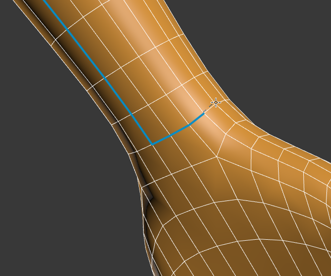
Figure 10-5: Select edge intersections around the wrist to complete the forearm/wrist seam.
- Right-click to deactivate the Point-To-Point Seams tool’s rubber banding but keep the button active; then continue cutting a new set of UVs for the right arm, just as you did for the left arm.
- Again right-click and then continue cutting around the torso area; go around the arms at the shoulder and also around the top of the legs, as shown in Figure 10-6.
- Using the Point-To-Point Seams tool, cut seams for the hands lengthwise down the middle from wrist to wrist. Begin at the wrist on the side of the thumb and work your way around the fingers to the opposite side of the wrist. You can see this progression for the left-hand start in Figure 10-7.
- Cut another seam from the inside of the left leg down to the ankle. Then continue the seam around the ankle; right-click to complete. The seam is just on the inside of the leg, except where it wraps around the ankle.

Figure 10-6: Add these seams to define the torso area.

Figure 10-7: Cut a new seam around the hand, starting as shown in the left image. Cut a seam around the fingers, as shown in the middle image, finishing at the opposite side of the wrist, as shown in the right image.
- 15. Create the seam for the right leg in the same way; the seams for both legs are shown in Figure 10-8.

Figure 10-8: Using the Point-To-Point Seams tool to cut the seams for the left and right legs.
- Continue creating seams for the left foot, using the Point-To-Point Seams tool. Start at the back of the foot and create a seam encircling the foot, as shown in Figure 10-9.
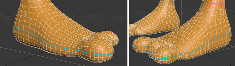
Figure 10-9: Cut a seam around the foot.
- Repeat the same seam on the right foot.
- Now for the head, start at the base of the back of the neck. Cut a seam up to the base of the nose, shown in Figure 10-10 (right image).
- Cut the seam around the base of the nose. The completed head seam is shown in Figure 10-10 (left image).
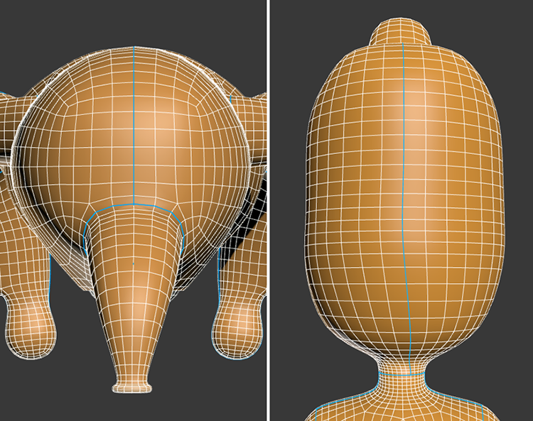
Figure 10-10: Cut seams for the head. Right image shows seams on the back of the head; left image shown seam that runs around the base of the nose.
- For the nose, start at the base located at the top of the head. Cut a seam up to the base of the nostril. Cut a seam around the base of the nostril, as shown in Figure 10-11.
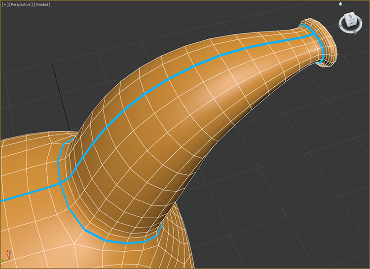
Figure 10-11: Cut seams for the nose.
- Cut a seam from the top of the nostril into the center of the nostril.
- Save your work before continuing with the next section. To check your work open the
c10_ex1_seam_end.maxfile.
Unwrap UVs on the Alien’s Body
Now that the alien’s body has seams cut it’s time to Unwrap the seamed parts. When sewing clothing you cut the fabric from patterns. Similarly, in this next section you will spread out the patterns so you can paint them to create the texture for the alien surface.
Exercise 10.2: Unwrapping the Alien’s Arm
Continue with the scene file from the previous section or open the c10_ex2_unwrap_start.max from the scenes folder of the c10_UnwrapUV project folder.
- Select the alien, go to the Modify panel, and in the Unwrap UVW modifier in the Edit UVs rollout, select the Open UV Editor button.
- In the top right of the window, from the drop-down menu choose CheckerPattern (Checker). This will apply a low-contrast checker map to the alien, as shown in Figure 10-12.

Figure 10-12: A low-contrast checker pattern is added to the alien model.
- With Polygon mode selected in your Unwrap UVW modifier and Point-to-Point Seams toggled off, click on a polygon on the left forearm of your model, and then in the Peel rollout, click the Expand Polygon Selection To Seams icon (
 ). This will select all the polygons that were included when creating seams for the arm, as shown in Figure 10-13.

Figure 10-13: The arm’s polygons are selected.
- To unfold the UVs into a usable pattern, click the Pelt Map icon (
 ) in the Peel rollout. The Pelt Map dialog box opens.
 - In the Edit UVWs dialog box, click the View menu and toggle off Show Grid and Show Map to simplify the UV view. Before moving on, take a look at the checkerboard pattern on the arm of the alien to recognize how it changes once you pelt, as shown in Figure 10-14.

Figure 10-14: The Edit UVWs and Pelt Map dialog boxes showing the left arm UVs
- To unfold the map, click the Start Pelt button in the Pelt Map dialog box. Doing so moves the UVs in the Edit UVWs dialog box in real time, as shown in Figure 10-15.
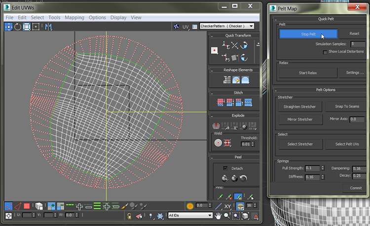
Figure 10-15: In the Pelt Map dialog box, use Start Pelt to unfold the UVs of the alien’s arm.
- This procedure keeps unfolding the UVs until you stop it, so wait a couple of seconds for the UVs to stop moving and then click Stop Pelt. You’re almost finished with the arm; however, if you look at the checkerboard texture in your viewport, you can see that some of the checks are bigger than others. To fix this, complete the remaining steps.
- Click the Settings box next to the Start Relax button in the Pelt Map dialog box. The Relax Tool dialog box opens. Change the drop-down option to Relax By Polygon Angles.
- Now, click the Start Relax button in the Relax Tool dialog box. Let Relax run for a good bit until the image matches Figure 10-16.
- Wait until the UVs stop moving and then click Stop Relax. If it still doesn’t match the figure, click Start Relax; then click Apply.
- Close the Relax Tool dialog box.
- Check your texture in the viewport; it now shows the checkerboard the way you want it.

Figure 10-16: Use the Start Relax button to relax the UVs.
- Click the Commit button at the bottom of the Pelt Map dialog box, or your changes won’t take effect.
- Close the Edit UVWs dialog box.
- Repeat steps 1 through 12 for the right arm. You can see in Figure 10-17 that both arms are now laid out—pelted and relaxed.

Figure 10-17: Both arms are pelted and relaxed.
- Save your work before continuing with the next section. To check your work open
c10_ex2_unwrap_end.max.
Exercise 10.3: Unwrapping the Alien’s Body
Now that you have the arms finished, you have an idea what needs to be done. It’s time to unwrap the remaining parts of the body, starting with the alien’s torso. Continue with the scene file from the previous section or open c10_ex3_unwrap_start.max from the scenes folder of the c10_UnwrapUV project folder.
- Select the alien, go to the Modify panel, and enter Polygon mode of the Unwrap UVW modifier.
- Select a single polygon on the alien’s torso (front or back, it doesn’t matter). In the Peel rollout, click the Expand Polygon Selection To Seams icon; this will select all the faces that were included when creating seams for the torso.
- Click the Pelt Map icon to open the Edit UVWs dialog box and the Pelt Map dialog box. First, click Start Pelt. You will see the UVs moving around. When they stop moving, click the Stop Pelt button.
- Now, click the Settings button next to the Start Relax button.
- Make sure the drop-down menu is set to Relax By Polygon Angles. Click Apply, and then close the Relax Tool dialog box.
- Click the Start Relax button again, and when the UVs stop moving, click Stop Relax.
- Click the Commit button. The checker pattern on the torso should look organized and even, as shown in Figure 10-18.

Figure 10-18: The alien’s backside with its UVs pelted and relaxed, showing the checker pattern evenly laid out
- Now that you have finished with part of the torso, repeat the process on the part of the torso you didn’t do in the previous steps.
- Repeat the process from steps 1–7 until all the remaining body seams on the alien’s body are pelted and relaxed.
Save your work before continuing with the next section. To check your work open c10_ex3_unwrap_end.max.
Exercise 10.4: Arranging the Alien’s UVs
When the UVs are unwrapped, the squares in the checker pattern on different parts of the alien are different sizes. They need to be set to the same size, showing that the UVs are uniform. Using the Select By Element UV Toggle tool will help with this process. It allows you to select an individual element’s full set of UVs so that you can scale and lay them out separately. Give them some space on the flat blank canvas so they can be used later for painting the textures for those parts of the body. Look in the UV Editor and you should see the blue-bordered box. It will look like a mess; these are all the unwrapped UVs piled on top of each other.
The UV layout can vary depending on many factors, as we said earlier. The goal is to fit the UVs into this box without going outside it and without overlapping any of them. Anything outside this box ends up tiling (or having no texture at all), and any overlapping UVs share parts of the texture from another element. Either way, that’s not good. Once you have the layout, you can select the UVs and move them around.
Continue with the scene file from the previous section or open c10_ex4_arrange_start.max from the scenes folder of the c10_UnwrapUV project folder.
- Select the alien and go to the Modify panel; enter Polygon mode of the Unwrap UVW modifier.
- In the Unwrap UVW modifier ⇒ Edit UVs and select Open UV Editor.
- Click the Select By Element UV Toggle, as shown in Figure 10-19.

Figure 10-19: Click the Select By Element UV Toggle.
- In the Edit UVWs dialog box, click on the “mess”; one part of the alien will be selected, as shown in Figure 10-20.

Figure 10-20: Select an element in the Edit UVWs dialog box, and it will appear as selected on the model.
- In the Edit UVWs dialog box, drag a selection box around all the UVs.
- From the Arrange Elements rollout on the right side of the Edit UVWs dialog box, change the Padding type-in field to 0.0 and then click the Pack Normalize button, as shown in Figure 10-21. The results of the Pack Normalize command are shown in Figure 10-22.
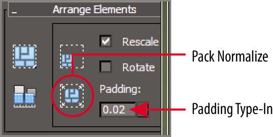
Figure 10-21: The Arrange Elements rollout

Figure 10-22: UVs placed within the UV space
- In the Edit UVWs dialog box, select Tools ⇒ Render UVW Template to open the Render UVs dialog box.
- Click the Render UV Template button in the Render Map dialog box to create an image of your UVs, as shown in Figure 10-23. Remember, the layout of the UV rendered image can vary.
- Save the UV layout image by clicking the Save Image icon in the Render Map dialog box, as shown in Figure 10-24.
- In the Save Image dialog box name the UV layout image Alien UV, and change Save As Type to TIF Image File (*.tif, *.tiff). Save the UVs in the
sceneassets/imagesfolder.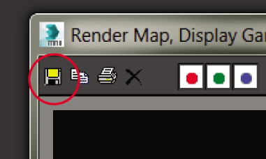
Figure 10-23: Use Save Image button to create UV layout image.

Figure 10-24: The UV layout image.
Once the UVs are saved, you can close all the UV image boxes and the Edit UVWs dialog box. Now you can open this image in your favorite image editor, and you can use the pieces as guides to paint the alien’s textures. Save your work before continuing with the next set of steps. To check your work open c10_ex4_arrange_end.max from the scenes folder of the c10_UnwrapUV project folder.
Build the Material and Apply It to the Alien
With the UV layout image saved, you can go into Photoshop (or the image-editing software of your choice) and create a texture to place on your model. For example, we took the UV image into Photoshop and used painting to create the final map for the alien, as shown in Figure 10-25.

Figure 10-25: The final map for the alien
The texture map, as you can see, places painted parts of the alien’s body according to the UV layout you just created. For example, you can clearly see the alien’s eye socket painted in middle of the texture image file.
Exercise 10.5: Applying the Color Map
Now it is time to use the map you put so much effort into creating. Continue with the scene file from the previous section or open c10_ex5_colormap_start.max from the scenes folder of the c10_UnwrapUV project folder.
- Open the Slate Material Editor (M).
- In the Material/Map Browser, expand the Materials rollout, and on the Standard rollout, drag and drop a Standard material onto the View1 window. Double-click the material node title bar to load the parameter into the Material Parameter Editor. Rename the material Alien.
- Double-click the Diffuse Color input socket of the material to open the Material/Map Browser.
- In the Maps rollout, expand the Standard rollout and double-click Bitmap.
- When the Select Bitmap Image File dialog box appears, navigate to the
sceneassetsimagesfolder for thec10_UnwrapUVproject and select and open theAlien_ColorMap.tiffile. - Apply the material to the alien, and click Show Shaded Material in Viewport.
The result is shown in Figure 10-26. Now wasn’t all that hard UV work worth it? If the blue seams are showing, go back to the Modify panel and select the Unwrap UVW modifier. Go to the Configure rollout and uncheck Peel Seams.

Figure 10-26: The alien with the material applied
Save your work before continuing with the next set of steps. To check your work open c10_ex5_colormap_end.max from the scenes folder of the c10_UnwrapUV project folder.
Exercise 10.6: Applying the Bump Map
Bump mapping makes an object appear to have a bumpy or irregular surface by simulating surface definition. When you render an object with a bump-mapped material, lighter (whiter) areas of the map appear to be raised on the object’s surface, and darker (blacker) areas appear to be lower on the object’s surface, as shown in Figure 10-27.

Figure 10-27: Bump map created in Photoshop by desaturating the original color map to create light and dark areas that conform to the original color texture
You can use this mapping technique to create additional surface detail. Bump maps are simple to create because you can usually take the color map and just desaturate it to make a grayscale image file. You will continue with the Alien material you created in the previous exercise as you add the new map. Continue with the scene file from the previous section or open c10_ex5_bumpmap_start.max from the scenes folder of the c10_UnwrapUV project folder.
- Double-click the Bump input socket of the material to open the Material/Map Browser.
- Under the Maps rollout, expand the Standard rollout and choose Bitmap.
- When the Select Bitmap Image File dialog box appears, navigate to the
sceneassetsimagesfolder of thec10_UnwrapUVproject folder and select theAlien_BumpMap.tiffile. - Double-click the material’s title bar to show the main material parameters.
- In the Maps rollout, set Bump Amount to 30.
The bump map is applied and finished. See Figure 10-28 for an image with the bump map. You may notice that the bump map has created a lot more detail in the alien’s body. You will notice the difference even better in your own renders.

Figure 10-28: Alien rendered with the bump map
Save your work before continuing with the next set of steps. To check your work open c10_ex6_bump_end.max from the scenes folder of the c10_UnwrapUV project folder.
Exercise 10.7: Applying the Specular Map
Highlights in objects are reflections of a light source. Specular maps are maps you use to define a surface’s shininess and highlight color, without the complex calculations of reflections in the render. The higher a pixel’s value (from black to white, or 0 to 1, respectively), the shinier the surface will appear at that location. You will be adding a specular map to the alien to increase the amount of detail you can get from the render, as shown in Figure 10-29.

Figure 10-29: The specular map for the alien
Continue with the scene file from the previous section or open c10_ex7_spec_start.max from the scenes folder of the c10_UnwrapUV project folder.
- Double-click the Specular Color input socket of the material to open the Material/Map Browser.
- Under the Maps rollout, expand the Standard rollout and choose Bitmap.
- When the Select Bitmap Image File dialog box appears, navigate to the
sceneassetsimagesfolder for thec10_UnwrapUVproject and select theAlien_SpecularMap.tiffile. - Double-click the material’s title bar to show the main material parameters.
- In the Specular Highlights group, set Specular Level to 50 and Glossiness to 40.
The final render of the alien is shown in Figure 10-30. You can see the improvement to the appearance of the alien’s bumps with the added specular color map.

Figure 10-30: Final render of the alien with the specular map applied
Save your work. To check your work open c10_ex7_spec_end.max from the scenes folder of the c10_UnwrapUV project folder.