Chapter 13
Introduction to Lighting: Interior Lighting
Light reveals the world around us and defines shape, color, and texture. Lighting is the most important aspect of computer graphics (CG), and it simply cannot be mastered at a snap of the fingers. The trick to correctly lighting a CG scene is to understand how light works and to see the visual nuances it has to offer.
In this chapter, you will study the various tools used to create light in the Autodesk® 3ds Max® software. This chapter will serve as a primer on this important aspect of CG. It will start you on the path by showing you the tools available and giving you opportunities to begin using them.
In this chapter, you will learn to:
- Recognize 3ds Max lights
- Light a still life
- Select shadow types
- Create atmospheres and effects
- Utilize the Light Lister tool
Recognizing 3ds Max Lights
The 3ds Max program has two types of light objects: photometric and standard. Photometric lights are lights that possess specific features to enable a more accurate definition of lighting, as you would see in the real world. Photometric lights have physically based intensity values that closely mimic the behavior of real light. Standard lights are extremely powerful and capable of realism, but they are more straightforward to use than photometric lights and less taxing on the system at render time. In this chapter, we will discuss only the standard lights.
Standard Lights
The 3ds Max lights attempt to mimic the way real lights work. For example, a light bulb that emits light all around itself would be an omni light in 3ds Max terminology. A desk lamp that shines light in a specific direction in a cone shape would be a spotlight. Each of the different standard lights casts light differently. We will look at the most commonly used lights.
The 3ds Max program has a total of eight light types in its Standard Light collection:
- Target spotlight
- Target direct light
- Free spotlight
- Free direct light
- Omni light
- Skylight
- mr area omni light
- mr area spotlight
The last two on this list begin with mr to signify that they are mental ray–specific lights (see Chapter 15, “mental ray,” for more about mental ray). An advanced renderer, mental ray is commonly used in production today. It offers many sophisticated and frequently complex methods of lighting that enhance the realism of a rendered scene. In this chapter, we will cover only the first five standard lights.
Target Spotlight
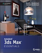
A target spotlight, as shown in Figure 13-1, is one of the most commonly used lights because it is extremely versatile. A spotlight casts light in a focused beam, similar to a flashlight. This type of lighting allows you to light specific areas of a scene without casting any unwanted light on areas that may not need that light. You can control the size of the hotspot, which is the size of the beam before it starts losing intensity.
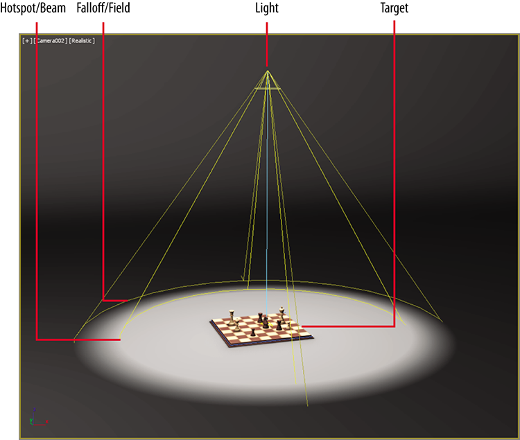
Figure 13-1: A target spotlight
The light is created with two nodes: the light itself (light source) and the target node, at which the light points at all times. This way, you are easily able to move the light following the subject of the scene, as a spotlight would follow a singer on stage. Select the target and move it as you would any other object. The target spot rotates to follow the target. Similarly, you can move the light source, and it will orient itself accordingly to aim at the stationary target. To see the Spotlight Parameters, select the light source, go to the Modify panel, and open the Spotlight Parameters rollout, shown in Figure 13-2.
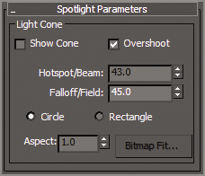
Figure 13-2: The Spotlight Parameters rollout
The falloff, which pertains to standard lights in 3ds Max software, is represented in the viewport by the area between the inner, lighter yellow cone and the outer, darker yellow cone, shown in Figure 13-2. The light diminishes to 0 by the outer region, creating a soft area around the hotspot circle (where the light is the brightest), as shown in Figure 13-3.

Figure 13-3: The falloff of a spotlight
Target Direct Light
A target direct light has target and light nodes to help you control the direction of the light. It also has a hotspot and beam, as well as a falloff, much like the target spot. However, whereas the target spot emits light rays from a single point (the light source) outward in a cone shape, the target direct light casts parallel rays of light within its beam area. This helps simulate the lighting effect of the sun because its light rays (for all practical purposes on Earth) are parallel. Figure 13-4 shows a target direct light in a viewport.

Figure 13-4: A target direct light
You can create and select/move parts of a target direct light in much the same way as a target spot. In the Directional Parameters rollout, you’ll find the similar parameters for the target direct light. Although the spotlight and the directional light don’t seem to be very different, the way they light is strikingly different, as you can see in Figure 13-5. The spotlight rays cast an entirely different hotspot and shadow than the directional light, despite having the same values for those parameters.
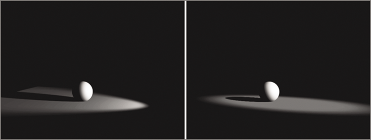
Figure 13-5: A target spot (left) and a target direct (right)
Free Spot or Free Direct Light
Free spotlights and free direct lights are virtually identical to target spots and target direct lights, respectively, except that the free spot and direct lights have no Target object. You can move and rotate the free spot however you want, relying on rotation instead of a target to aim it in any direction, as shown in Figure 13-6.

Figure 13-6: Free spot (left) and free direct (right) lights
Another difference between a free spot or direct light and a target spot or direct light is that while the length of the target spotlight is controlled by its target, a free spot or direct light instead has, in the General Parameters rollout, a parameter called Targ. Dist. The default is 240 units.
Free spot and free direct (as well as target spot and target direct) lights are great for creating the main lighting in your scene, because they are very easy to control and give a fantastic sense of direction. In the General Parameters rollout, there is a drop-down menu allowing you to change your chosen light type to another type. You can also change a free light to a target light by checking the Targeted box.
Omni Light
The 3ds Max omni light is a point light that emanates light from a single point in all directions around it. Figure 13-7 shows an omni light. Unlike the spot and directional lights, the omni light does not have a special rollout, and its General Parameters rollout is much simpler.
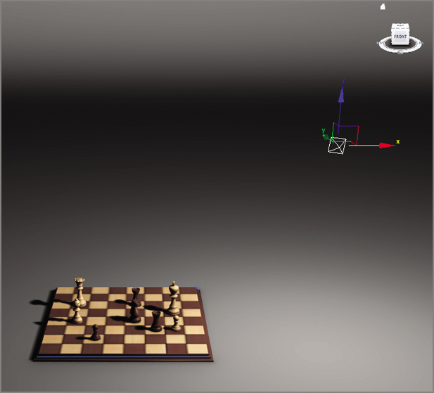
Figure 13-7: An omni light is a single-point-source light.
Omni lights are not as good for simulating sunlight as directional lights are. In Figure 13-8, the omni light in the image on the left creates different shadow and lighting directions for all the objects in the scene, and the directional light in the image on the right creates a uniform direction for the light and shadow, as would the sun here on Earth.
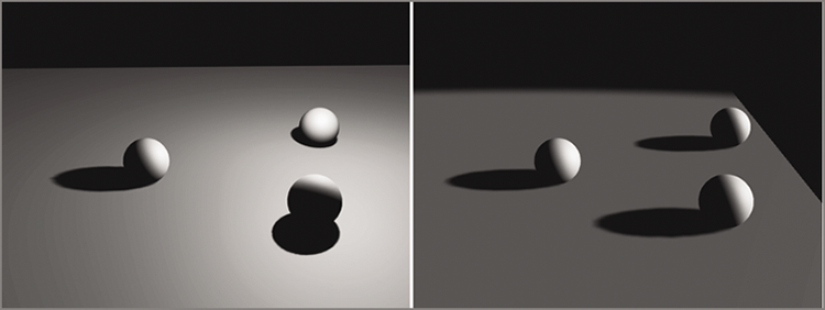
Figure 13-8: Omni light (left) and directional light (right)
Omni lights are good for fill lights as well as for simulating certain practical light sources.
Lighting a Still Life
Lighting a still life can be approached using the three-point lighting setup. Three-point lighting is a traditional approach to lighting a television shot. After all these years, the concepts still carry over to CG lighting. In this setup, three distinct roles are used to light the subject of a shot. The scene should, in effect, seem to have the following elements:
- Only one primary or key light to define lighting direction and create primary shadows
- A softer light to fill the scene and soften the shadows a bit
- A back light to make the subject pop out from the background
This does not mean there are only three lights in the scene. Three-point lighting suggests that there are three primary angles of light for your shot, dependent on where the camera is located.
Three-point lighting ensures that your scene’s main subject for a particular shot is well lit, has highlights, and has a sense of lighting direction using shadow and tone. Figure 13-9 shows a plan view of the three-point lighting layout. The subject is in the middle of the image.
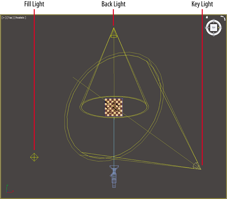
Figure 13-9: A three-point lighting schematic
Exercise 13.1: Basic Light Setup
Now that you have an overview of how lights work in a 3ds Max scene, let’s put them to good use and light the room from Chapter 9, “Introduction to Materials: Interiors and Furniture,” and create a basic light setup for the scene. Set your current project to the c13_IntroLight you copied to your hard drive from this book’s web page, www.sybex.com/go/3dsmax2015essentials. Open c13_ex1_basic_start.max from the scenes folder of the c13_IntroLight project folder.
- Go to the Create panel and select the Lights icon (
 ) to bring up the selection of lights you can create.
 - Click the drop-down menu and choose Standard, as shown in Figure 13-10.
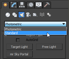
Figure 13-10: Choose Standard from the Lights drop-down menu.
- Select Target Spot and go to the Front viewport.
- Click and drag from the ceiling above the dining room table to the floor below the table. In the command panel, rename the light Key Light.
- In the Top viewport, use the Move tool to select the light and the target by dragging a selection box around both. Use the Zoom tool if needed to see the light selected.
- Move them so they are over the dining room table in the Top viewport, as shown in Figure 13-11.
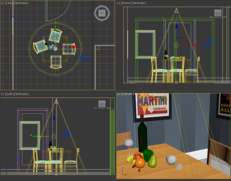
Figure 13-11: The spotlight’s position in the room
- Click away from any objects in the scene to deselect the light; then select just the source of the light object. Go to the Modify panel. In the Intensity/Color/Attenuation rollout, set Multiplier to 1.2.
- In the Still Life Camera viewport, click the Shading Viewport Label menu to expand it. Choose Realistic from the list.
- Click the Shading Viewport Label menu again, go down to Lighting and Shadows, and choose Illuminate with Scene Lights, as shown in Figure 13-12. Now the Still Life camera can be used to judge the lights and shadows for this scene.

Figure 13-12: The Shading Viewport Label menu
- Go to the Modify panel and expand the Spotlight Parameters rollout.
- Set Hotspot/Beam to 40 and Falloff/Field to 100. As you can see in the Still Life Camera viewport, the light spreads out farther toward the walls.
- Now render by clicking the Render Production button (
 ), which is on the main toolbar; the rendered image is shown on the left in Figure 13-13.
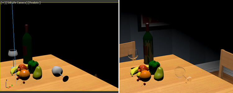
Figure 13-13: The Still Life Camera viewport set to Realistic, showing new Hotspot/Beam and Falloff/Field settings (left); the rendered scene (right)
Save your file and move on to the next exercise. To check your work, open the c13_ex1_basic_end.max file from the scenes folder of the c13_IntroLight project folder.
Exercise 13.2: Adding Shadows
Using shadows intelligently is important in lighting your scenes. Without the shadows in the scene, the still life would float and have no contact with its environment.
Continue with the file you are working on or open c13_ex2_shadows_start.max from the scenes folder of the c13_IntroLight project folder.
- Select the key light, if it isn’t already selected.
- In the Modify panel, go to the General Parameters rollout ⇒ Shadows area and check the On box.
- In the Still Life Camera viewport, a low-resolution version of the shadows appears, but a render of the scene will show it more accurately.
- Render the scene. The result is shown in Figure 13-14.

Figure 13-14: It looks good, but the scene shadows are too soft.
- Go to the Shadow Map Params rollout and change Size to 2048. This parameter adds more pixels to the shadow, which makes it more defined and less diffused.
- Render the Still Life Camera viewport, as shown in Figure 13-15.

Figure 13-15: The render showing more defined shadows
Save your file and move on to the next exercise. To check your work, open the c13_ex2_shadows_end.max file from the scenes folder of the c13_IntroLight project folder.
Exercise 13.3: Adding a Fill Light
In the viewport, the shadow already looks better, but in the render, because the glasses are transparent, the shadow looks a bit weird—too dark and solid for a shadow for a transparent glass. To fix this issue, the shadow’s density needs to be lowered. Adding a light to fill in the very dark shadows will correct this issue. A fill light simulates the indirect light seen in the real world. A fill light should not have any shadows or specular highlights; without them you can make sure the render looks as if there is only one light in the room. Continue with the file you are working on or open c13_ex3_fill_start.max from the scenes folder of the c13_IntroLight project folder.
- In the Create panel, select Lights ⇒ Omni, and in the Top viewport, click to create the omni light in the lower-right corner of the dining room.
- In the Front viewport, move the omni light up so it is just below the ceiling of the dining room, and change the name to Fill Light.
- In the Intensity/Color/Attenuation rollout, change Multiplier to 0.2. By default, shadows are always off, but you must turn off specular highlights manually.
- With the omni light selected, go to the Modify panel and under the Advanced Effects rollout uncheck Specular.
- Render again (press F9), and you’ll see that the render looks better, but the still life’s shadows are still dark, as shown in Figure 13-16. To fix the darkness of the shadow, the density of the shadow needs to be adjusted.

Figure 13-16: Interior room with key light and fill light
- Select the key light, go to the Modify panel, and in the Shadow Parameters rollout change the Object Shadows Dens parameter to 0.8.
- Render the Still Life Camera viewport again by selecting the Render Production icon (F9) in the main toolbar. The shadows look much better, as shown in Figure 13-17.

Figure 13-17: Shadows with Density set to 0.8
Save your file and move on to the next exercise. To check your work, open the c13_ex3_fill_end.max file from the scenes folder of the c13_IntroLight project folder.
Exercise 13.4: Attenuation of the Fill Light
The omni light needs to have decay or attenuation applied. This means that light over distance loses its intensity or energy. Standard lights don’t do this by default; it has to be simulated within the parameters. Continue with the file you are working on or open c13_ex4_attenuation_start.max from the scenes folder of the c13_IntroLight project folder.
- Select the omni light. In the Intensity/Color/Attenuation rollout, click the Use and Show check boxes under Far Attenuation, as shown in Figure 13-18. The Start value defines the start of the decay of the light. The End value defines when the light drops off to zero. This is best seen in the Top viewport, as shown in Figure 13-19.
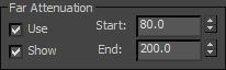
Figure 13-18: Check the Use and Show boxes for Far Attenuation.

Figure 13-19: Far Attenuation set on the fill light as viewed from the Top viewport with all the scene objects hidden
- Set the Start value to 120.0 and the End value to 200.0; this gives some variation to the fill light, as shown in Figure 13-20.

Figure 13-20: A still life rendered with Far Attenuation
Save your file and move on to the next exercise. To check your work, open the c13_ex4_attenuation_end.max file from the scenes folder of the c13_IntroLight project folder.
Selecting a Shadow Type
To get shadows to respond to transparencies, you will need to use raytraced shadows instead of shadow maps.
You can create the following types of shadows using the 3ds Max program:
- Advanced raytraced
- mental ray shadow map
- Area shadows
- Shadow map
- Raytraced shadows
Each type of shadow has its benefits and its drawbacks. The two most frequently used types are shadow map (which you’ve already seen) and raytraced shadows.
Shadow Maps
Using a shadow map is often the fastest way to cast a shadow. However, shadow map shadows do not show the color cast through transparent or translucent objects.
When you are close to a shadow, to avoid jagged edges around it, use the Size parameter to make the resolution higher. The following parameters are useful for creating shadow maps:
- Bias The shadow is moved, according to the value set, closer to or farther away from the object casting the shadow.
- Size Detailed shadows need detailed shadow maps. Increase the Size value, which in turn increases the detail of the shadow cast. Figure 13-21 compares using a low Shadow Map Size setting to using one four times larger. Notice how the shadows on the left (Size = 1024) are somewhat mushy and less noticeable, and the shadows on the right (Size = 4096) are crisp and clean. A size around 2048 is good for most cases. Scenes like this chessboard that have a large scale require higher Size values, such as the 4096 that was used.
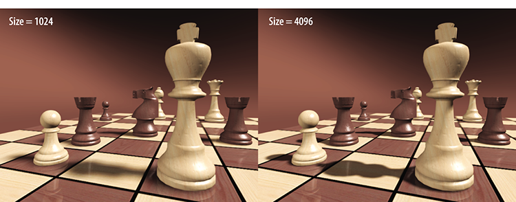
Figure 13-21: The Shadow Map Size setting affects the shadow detail.
- Sample Range This option creates and controls the softness of the edge of shadow map shadows. The higher the value, the softer the edges of the shadow.
Raytraced Shadows
Raytracing involves tracing a ray of light from every light source in all directions and tracing the reflection back to the camera lens. You can create more accurate shadows with raytracing than with other methods, at the cost of longer render times. Raytraced shadows are realistic for transparent and translucent objects. Figure 13-22 shows the still life rendered with a plane object casting a shadow over it. The plane has a logo mapped to its Opacity map channel, so it has alternating transparent and opaque areas defining the solid and transparent parts of the logo. On the left side of the image in Figure 13-22, the light is casting shadow map shadows; and on the right, the light is casting raytraced shadows.

Figure 13-22: The image on the left shows the shadow maps, which do not show transparencies. The image on the right show raytraced shadows and how they react to transparencies.
Use raytraced shadows when you need highly accurate shadows or when shadow map resolutions are just not high enough to get you the crisp edges you need. You can also use raytraced shadows to cast shadows from wireframe rendered objects.
The Ray Traced Shadow Params rollout controls the shadow. The Ray Bias parameter is the same as the Shadow Map Bias parameter in that it controls how far the shadow is from the casting.
Atmospherics and Effects
Atmospherics provides effects such as parallel beams of fog seen within light rays, and glows. Atmospheric effects with lights, such as fog or volume lights, are created using the Atmospheres & Effects rollout in the Modify panel for the selected light. Using this rollout, you can assign and manage atmospheric effects and other rendering effects that are associated with lights.
Exercise 13.5: Creating a Volumetric Light
Volume Light is a light effect based on the interaction of a light with atmosphere. In the real world, this effect is visible when there’s a lot of dust in an enclosed space.
- Open the
c13_ex5_volume_start.maxfile from thescenesfolder of thec13_IntroLightproject folder. - Go to the Create panel, select Lights, and in the drop-down list select Standard, and then select the Target Direct light.
- Go to the Left viewport and, clicking from the left outside of the room, position the light at a high angle from the window. Drag toward the living room window and click to set the light on the floor inside the room.
- Select the Move tool, and then in the Top viewport click the line that connects the light and its target, which will select both easily. Move the light so it is aligned with the living room window, as shown in Figure 13-23.
- Select the light source only and name the light Sunlight.
- Click the Shading Viewport Label menu to expand it. Choose Realistic from the list. Click the Shading Viewport Label menu again, go down to Lighting and Shadows, and choose Illuminate with Scene Lights.

Figure 13-23: The light’s position shown in all the viewports
- Select the Sunlight object and go to the Modify panel. In the General Parameters rollout check On in the Shadows group. Use the default Shadow type, which is Shadow Map.
- In the Intensity/Color/Attenuation rollout, change the Multiplier to 1.2.
- In the Directional Parameters rollout, change Hotspot/Beam to 60.0 and Falloff/Field to 63.0. Looking at the Chess Set Camera viewport, you will see the light coming in through the window, but it is very dark everywhere else, as shown in Figure 13-24. More lights need to be added.

Figure 13-24: Interior room with the direct light in place as the sun
- In the Create panel, select Lights ⇒ Omni, and place the light near the Sunlight’s position. Name the light Fill Light 1.
- With the omni light selected, go to the Modify panel, and in the Intensity/Color/Attenuation rollout, change Multiplier to 0.5.
- In the Intensity/Color/Attenuation rollout, in the Far Attenuation section, check Use and set Start to 150.0 and End to 400.0.
- In the Advanced Effects rollout, uncheck the Specular check box. This keeps the light on but does not show any specular highlights from this light.
- Select the Sunlight light, and from the Modify panel, open the General Parameters rollout.
- Go to the Shadow Map Params rollout and set the size to 2048 and change Sample Range to 2.0; this will add some sharpness to the shadow’s edge and make it more like a daylight shadow.
- In the Create panel, select Lights ⇒ Omni, and place the light behind the Chess Set Camera.
- Move the light so it is just below the ceiling. Name the light Fill Light 2.
- With the omni light selected, go to the Modify panel, and in the Intensity/Color/Attenuation rollout, change Multiplier to 0.3.
- In the Advanced Effects rollout, uncheck the Specular check box.
- In the Intensity/Color/Attenuation rollout, in the Far Attenuation section, check Use and set Start to 48.0 and End to 400.0.
- Select the Sunlight light. In the Sunlight’s parameters, go to the Atmospheres and Effects rollout.
- Select Add from the rollout to open the Add Atmosphere or Effect dialog box, select Volume Light, and click OK to add the effect to the light. Volume Light will be added to the rollout.
- Render the scene. You should see a render similar to Figure 13-25.
- To adjust the volume light, go back to the Atmospheres and Effects rollout, select the Volume Light entry, and click the Setup button. This will bring up the Environment and Effects dialog box.

Figure 13-25: Ooh! Volume light!
- Scroll down to the Volume Light Parameters section to access the settings for the volume light, as shown in Figure 13-26.
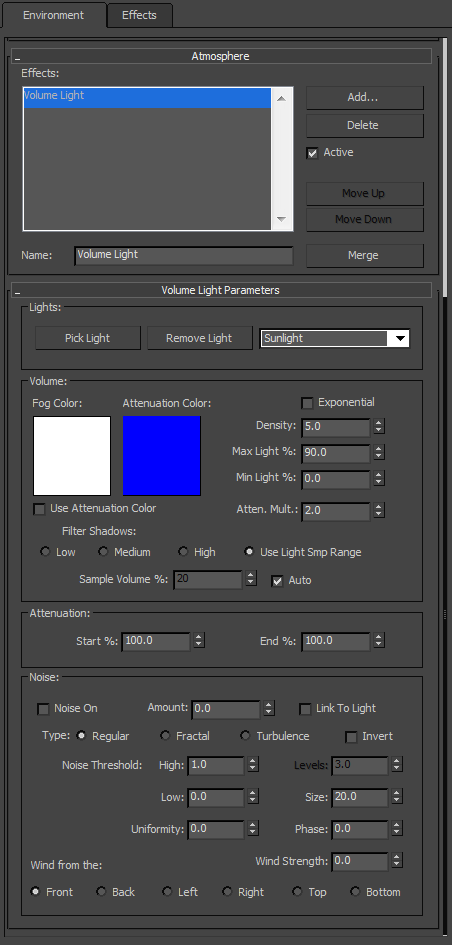
Figure 13-26: The Environment and Effects dialog box displays the Volume Light parameters.
- In the Volume section, change Density to .25. This lessens the intensity of the volume and makes it more realistic.
- Change Max Light % to 10.0.
- Render the Chess Set Camera viewport; the results are shown in Figure 13-27.

Figure 13-27: The final results of the volume light in the interior room
Save your file. To check your work, open the c13_ex5_volume_end.max file from the scenes folder of the c13_IntroLight project folder.
Volume Light Parameters
The default parameters for a volume light will give you some nice volume in the light for most scenes, right off the bat. If you want to adjust the volume settings, you can edit the following parameters:
- Exponential The density of the volume light will increase exponentially with distance. By default (Exponential is off), density will increase linearly with distance. You will want to enable Exponential only when you need to render transparent objects in volume fog.
- Density This value sets the fog’s density. The denser the fog is, the more light will reflect off the fog inside the volume. The most realistic fog can be rendered with about a 2 to 6 percent density value, depending on the scene.
Most of the parameters are for troubleshooting volume problems in your scene if it is not rendering very well. Sometimes you just don’t know what the problem is and you have to experiment with switches and buttons.
The Noise settings are another cool feature to add some randomness to your volume:
- Noise On This toggles the noise on and off. Render times will increase slightly with noise enabled for the volume.
- Amount This is the amount of noise that is applied to the fog. A value of 0 creates no noise. If the amount is set to 1, the fog renders with pure noise.
- Size, Uniformity, and Phase These settings determine the look of the noise and let you set a noise type (Regular, Fractal, or Turbulence).
Adding atmosphere to a scene can heighten the sense of realism and mood. Creating a little bit of a volume for some lights can go a long way to improve the look of your renders. However, adding volume to lights can also slow your renders, so use it with care.
The Light Lister
If several lights are in your scene and you need to adjust all of them, selecting each light and making one adjustment at a time can become tedious. This is where 3ds Max Light Lister comes in handy. Accessed through the menu bar by choosing Lighting/Cameras ⇒ Tools (Lights/Cameras Set) ⇒ Light Lister, this floating palette gives you control over all of your scene lights, as shown in Figure 13-28.
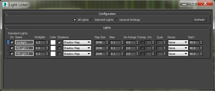
Figure 13-28: The Light Lister dialog box
You can choose to view or edit all the lights in your scene or just the ones that are selected. When you adjust the values for any parameter in the Light Lister dialog box, the changes are reflected in the appropriate place in the Modify panel for that changed light.