
IN THIS CHAPTER
Wired ethernet is the oldest network you can use at home. However, it’s still one of the best choices, especially if you plan to network just one or two rooms. Wired ethernet also works well as part of a mix-and-match network with wireless ethernet (Wi-Fi).
From installing adapters and building network cable to configuring your router and hiding your cable, this chapter is your guide to fast, inexpensive home networking with wired ethernet.
Wired ethernet (which includes 10BASE-T, Fast Ethernet, 10/100 Ethernet, and Gigabit Ethernet) doesn’t have the sex appeal of its wireless sibling, but if you’re looking for the cheapest, fastest, and easiest-to-configure home network around, wired ethernet’s worth considering.
What makes wired ethernet so inexpensive? First of all, consider the fact that most desktop and notebook computers built in the last couple of years include a 10/100 Ethernet (RJ-45) port, as you learned in Chapter 3, “Planning Your Home Network.” Even if your computer lacks an ethernet port, you can add one for less than $50. Second, 10/100 Ethernet routers (the devices that connect your network with the Internet) have never been cheaper, with many brands selling for around $50. Almost all routers include a switch, so you can use a single device to connect your computers to each other and to the Internet. Even if you decide to install a wireless ethernet(Wi-Fi) router incorporating a 10/100 Ethernet switch (perfect for building a mixed wired/wireless network), you won’t spend much more.
Note: Full Duplex for Super-Fast Ethernet Speed

Ethernet speed ratings assume half duplex operation: Each network adapter is reading data from another network station or sending (writing) data to another network station. When enabled, full duplex network hardware performs simultaneous read/write operations, pushing the effective speed of a 10/100 Ethernet network with Fast Ethernet hardware to 200Mbps, a cool 8×-or-more faster than the real-world speed of typical 802.11g Wi-Fi wireless nets. To maintain full duplex performance, always use a switch, never a hub, to add additional ports to your network.
Wired ethernet is blazing fast. The standard 10/100 Ethernet adapters and ports run at 100Mbps (Fast Ethernet speed) unless your network has some of the old 10BASE-T (10Mbps) network hardware. Even then, network switches create high-speed connections between 100Mbps devices. Better still, most recent 10/100 Ethernet network adapters and switches support full duplex. Some new computers feature Gigabit Ethernet (1000Mbps), which is also backward-compatible with 10/100 Ethernet.
Finally, wired ethernet is easy to configure. Run the Windows Home Networking wizard or manually configure a simple TCP/IP option called dynamic host configuration protocol (DHCP) on each computer, and each station on the network gets a unique IP address. Networking in business can be complicated, but ethernet networking at home is simple.
So, what’s the big rap against wired ethernet? The wires, of course. Long wire runs can add up to some serious bucks if you buy pre-built wire, wire colors are refugees from a crayon box, and they can be hard to run through walls. None of these are fatal objections, though. If economy, speed, and fixed locations are your goals, wired ethernet is your network, and this chapter will show you how to do it.
Tip: Mix-and-Match for Economy and Performance

In my own home network, I take full advantage of the mix-and-match capabilities of a wireless router, which also includes a switch. I run cables to close-in locations, and use the wireless feature for roving PCs such as my notebook computer. The techniques covered in this chapter work with both “pure” wired ethernet networks and with the wired component of a wired ethernet/Wi-Fi network.
If some of your notebook or desktop PCs don’t have on-board ethernet adapters, the following sections show you how to get your systems ready to join a wired ethernet network.
If all the hardware (PCs, home entertainment devices, video cameras, and so forth) is ethernet-ready, skip to “Hub, Switch, or Router? Making the Right Connectivity Choice” (p.109, this chapter) to continue.
Most, but not all, recent PCs already have a 10/100 Ethernet port. However, if your PC doesn’t, there are several ways to connect it to an ethernet network, as Table 5.1 reveals.
Table 5.1. Ethernet Adapters for PCs
Computer Type | Adapter Type | How Added | Benefits | Drawbacks |
|---|---|---|---|---|
Desktop | PCI | Installed into open PCI slot | Faster connection than USB or Hi-Speed USB port; lowest-cost adapter type | Requires opening PC; difficult to move between systems |
Notebook | PC Card | Installed into open PC Card or CardBus Type II slot | Easy to install | PC Card slot is slower than CardBus slot; card becomes useless if dongle is lost or damaged; can’t be used with desktop PCs |
Notebook | CardBus | Installed into open CardBus Type II slot | Easy to install; faster than PC Card | More expensive than PC Card; can’t be used with desktop PCs |
Desktop or Notebook | USB 1.1 | Connects to open USB 1.1 port | Easy to install or move; works in any system with a USB 1.1 port | Slower than CardBus or PCI; more expensive than PCI card |
Desktop or Notebook | Hi-Speed USB (USB 2.0) | Connects to open USB 2.0 or 1.1 port | Easy to install or move; works in any system with a USB port | Requires Hi-Speed USB port for best performance; more expensive than PCI card |
Which solution is right for you? From the standpoint of performance, choose these:
Desktop or notebook PC with Hi-Speed USB port: Hi-Speed USB (USB 2.0) adapter.
Desktop with open PCI card slot (but no Hi-Speed USB port): PCI card adapter
Notebook with open CardBus slot (but no Hi-Speed USB port): CardBus adapter
Note: The Process Is Similar with Other Adapter Types
Because other types of network adapters use similar installation processes, I’ll provide cross-references to this section in other chapters. After you complete these steps, return to the appropriate chapter for additional steps to follow to complete the installation process.
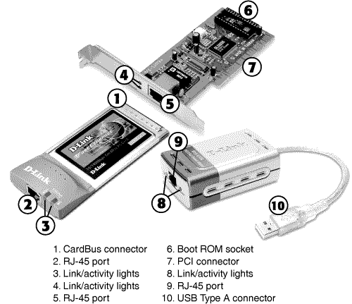
Although USB 1.1 adapters can be used with virtually any PC built in the last 5 or 6 years, the maximum speed of the port is just 12Mbps. PC Card adapters work in both recent notebooks and old models (CardBus slots also take PC Cards), but the PC Card’s 16-bit data bus limits performance compared to CardBus’s 32-bit data bus. Figure 5.1 shows typical examples of Hi-Speed USB, PCI, and CardBus 10/100 Ethernet network adapters.
If your system has a USB port, installing a USB ethernet adapter is far and away the simplest way to connect it to a wired ethernet network. Here’s how to do it:
Install the driver disk or CD for your USB adapter. Although USB is widely praised as a “plug-and-play” technology, plug-and-play assumes that your computer already “knows” about the device category and specific requirements of a given USB device. If you don’t install drivers for a specific USB device first, the system won’t recognize it, or might try to use an existing driver that won’t work.
Attach the USB cable to the adapter if necessary. Some ethernet adapters use a removable USB cable, and others use a built-in USB cable.
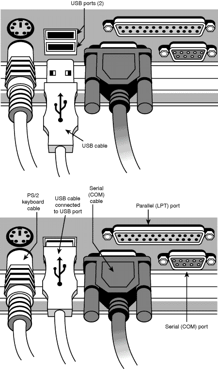
Plug the device directly into a USB port on your PC, or into a powered hub (Figure 5.2). USB ports in your PC output the full 500mA power requirement used by some USB devices, but USB ports in keyboard or other bus-powered hub usually provide only 100mA per port.
Provide the Windows CD if requested. This step is necessary if your system needs additional USB support from the Windows CD or if the necessary network protocols are not already installed.
Most recent notebook computers have one or two Type II CardBus slots. These slots can also handle PC Card devices. After you determine which type of card your system uses, the remainder of the installation process is almost identical:
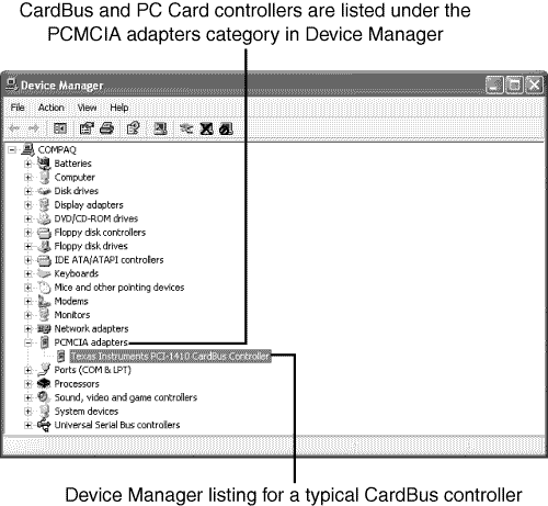
Determine whether your notebook computer has CardBus or PC Card slots. To find out which type of card slot your notebook computer uses, check your system documentation or use Windows Device Manager (Figure 5.4) to see whether your system has a CardBus controller.
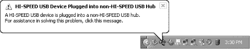
Note: Don’t Panic if You Mismatch Hi-Speed USB and USB 1.1
Windows XP will pop up a warning (Figure 5.3) if you connect a Hi-Speed USB device to a USB 1.1 port. Your device will work, but its speed will be limited by the slower speed of the port.
Insert the CardBus or PC Card into the appropriate slot. Note that if your system has only one CardBus or PC Card slot and you are already using it, you must eject the card first before you can insert another card. Use the Safely Remove Hardware utility in the Windows System Tray to stop the other card before you eject it.
Install the required drivers. Use the CD or floppy disk provided with the adapter, or point the installation program to updated drivers you have downloaded.
Tip: Already Using PC Cards? Check the End of the Connector
CardBus cards have a gold grounding strip on the connector end (refer to Figure 5.1), but 16-bit PC Cards do not. If you already use cards in your notebook computer, see whether any of them have a CardBus connector. If they do, you can use the faster CardBus interface for your network adapter.
Provide the Windows CD if requested. If your system hasn’t already been connected to the Internet or to another network, you might need to provide the Windows CD so that Windows can install the appropriate network protocols.
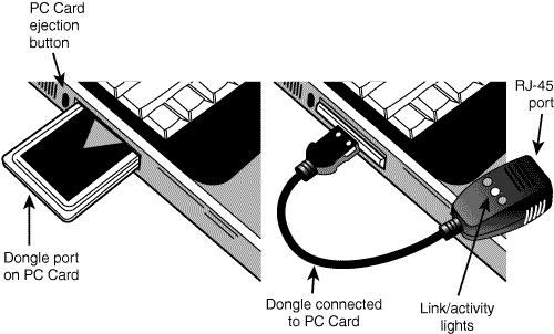
If the card is equipped with a dongle, connect it after the card is installed. Many older PC Card-based 10BASE-T, 10/100 Ethernet, or combo ethernet/modem cards use a removable dongle to connect standard cables to the narrow edge of a Type II card (Figure 5.5). If the dongle is lost or damaged, the card is useless until the dongle is replaced.
Tip: Handling the Windows/Driver CD-Swap Blues
If you need to remove your network driver CD and insert your Windows driver CD during installation, your system might “forget” what folder to use for files. If this happens, use the Browse button on the dialog box and navigate to the appropriate folder on the Windows or driver CD.
If you’ve already opened your system to install a memory, drive, or video card upgrade, installing a network adapter won’t be hard. However, if you’re embarking on your first journey inside your PC, keep the following in mind:
You need a Phillips screwdriver or hex driver to open your system and remove a card slot cover. As long as you keep your driver away from floppy or Zip disks, it’s OK to use a magnetic-tipped tool.
To avoid ESD (electrostatic damage), be sure to touch a metal part of the case before you open your PC. And, keep one hand on the power supply or another metal part while the system is open. Or, use a wrist strap.
Tip: A Wrist Strap’s the Way to Keep the ESD Blues Away
A commercial anti-ESD wrist strap uses an alligator clip to connect to a metal part of the PC to prevent the buildup of static electricity. You can buy them from a variety of computer-tool vendors, or you might find one included in a computer toolkit.
To install a PCI card in a desktop computer:
Take ESD precautions. Touch a metal part of the PC or use a wrist strap.
Turn off the system and unplug it. Run the Windows Shutdown procedure to shut down your system. If your power supply has a power switch, turn it off before you unplug the power cord.
Remove the screws holding the cover in place. Some systems use separate panels for each side of the cover, and others use a one-piece cover for the entire system.
Remove the cover. Some cases lift off the frame in one piece or in sections, and others slide off.
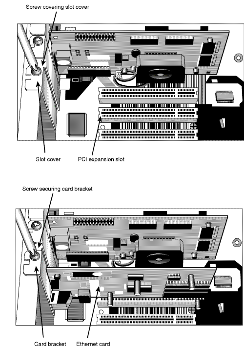
Locate an empty PCI expansion slot. See Figure 5.6 (top).
Remove the slot cover corresponding to the expansion slot. In most cases, the slot cover is held in place by a screw. However, some systems use a snap-out slot cover that might be disposable.
Line up the PCI card with the PCI slot and push it into place. See Figure 5.6 (bottom).
Fasten the card bracket to the case with the screw removed in step 5. See Figure 5.6 (bottom).
Close the case. If the case was removed in sections, be sure to reinstall case sections in the correct order.
Plug in the power supply and restart the system. If the power supply is turned off, turn it on before attempting to restart the system.
Provide the Windows and network adapter driver disk(s) or CDs when prompted. You might not need to provide disks or CDs with newer versions of Windows.
You can connect home entertainment devices such as home theater systems, stereos, TVs, personal video recorders, and video games to a wired ethernet network.
To add home theater systems, stereos, or TVs to your network, connect them to a media adapter. These devices include software that enables the device to connect with a PC that contains the photo, video, or music files you want to play and a remote control for selecting and playing the files. Although most media servers are marketed to users of Wi-Fi (802.11) wireless networks, the vast majority of them also support 10/100 or 10BASE-T wired Ethernet networks.
TiVo Series 2-compatible personal video recorders feature a USB port that can be used for ethernet or other types of USB network adapters. ReplayTV personal video recorders feature a built-in ethernet port.
The Microsoft Xbox is ready to connect to a wired ethernet network as soon as you take it out of the box. However, if you want to add a Sony PlayStation 2 to an ethernet network, you need to use Sony’s PlayStation 2 broadband adapter (included in recent systems or available separately) or a PlayStation 2-compatible USB to ethernet adapter. Similarly, you need the Nintendo GameCube broadband adapter if you want to connect a GameCube system to your network.
For more details about adding home entertainment hardware to any type of home network, see Chapter 7, “Home Networks at Play.”
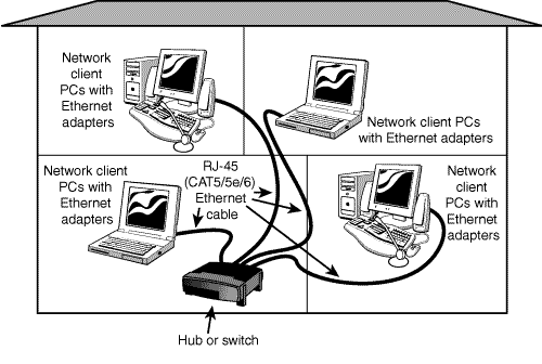
Stations on a 10/100 or 10BASE-T Ethernet network do not connect directly to each other. Instead, they are connected through a centralized device that receives and sends signals between the stations (Figure 5.7).
There are three types of devices that can be used to make the connection between stations in a wired ethernet network:
Hub—. Simplest of the three devices, a hub broadcasts to all devices on the network and subdivides the bandwidth of the network among connected devices. Thus, a 10/100 Ethernet network with four 100Mbps stations connected through a hub has an effective speed of 25Mbps (100/4).
Switch—. The switch creates a direct (one-to-one) connection between sending and receiving computers and provides full network speed for all stations. Most switches also provide full-duplex support.
Router—. A router connects one network (such as a LAN) to another (such as the Internet). Almost all routers made for home networking include a switch. Otherwise, a router can be connected to a switch or hub.
Note: Simplifying Terms
Although some wired ethernet home networks still use hubs, I will use the term switch in the remainder of this book to refer to the connection between PCs on a wired ethernet network. Because almost all routers contain integrated switches, I will use the term router to refer to a router that has an integrated switch or is connected to a separate switch.
If your network is used to share an Internet connection, you need a router, preferably with an integrated switch. Even if your home network doesn’t include Internet access now, the small price premium for routers with integrated switches over switches alone makes using a router preferable. Routers also provide IP addresses to the computers connected to them, making network setup relatively simple.
How can you tell whether a device is a hub, switch, or router? Table 5.2 provides a quick reference to the features of each type of device. Figure 5.8 compares these devices. In most cases, the signal lights shown in Figure 5.8 are on the front of each device, and the ports are on the rear of each device. Note that the switch has signal lights for full duplex, and the router has a WAN port and separate signal lights for the WAN connection to the Internet.
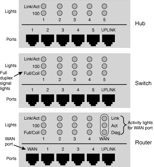
Table 5.2. Hub, Switch, and Router Feature Comparison
Features | ||||
|---|---|---|---|---|
Device Type | LAN Ports & Signal Lights | Full Duplex Indicator | WAN Port & Signal Light | Uplink Port |
Hub | Yes | — | — | Optional |
Switch | Yes | Yes | — | Optional |
Router | Yes[*] | Yes | Yes | Optional |
[*] A router with an integrated switch will have four or more LAN ports. A router without an integrated switch will have one LAN port to connect it to a hub or switch. | ||||
The Uplink ports shown in Figure 5.8 are used to connect the device to another device (see Figure 5.9 for an example).

Should you build your own ethernet cables or buy them? The answer to that question depends on the following factors:
Do you plan to run your cables through walls? If you do, it’s easier to snake raw cable than cable that already has connectors on each end. After the cable is in the walls, you can add connectors or, for a neater job, connect the ends to wall boxes.
Do you plan to network three or more devices at distances greater than 100 feet to the switch or router? If you plan to network three or more devices, especially with relatively long cable runs, it can make more sense economically to build your own cable. As an alternative, also consider building a mix-and-match network that uses wired ethernet for close-in devices and wireless ethernet (Wi-Fi) for longer (over 100 feet) distances. This is the approach I use in my home network.
However, if your home network includes only a couple of devices and you don’t need (or don’t want) to snake your cable through walls, you can save yourself a bit of trouble by using assembled cables.
Tip: Money-$aving Techniques for Custom Cabling
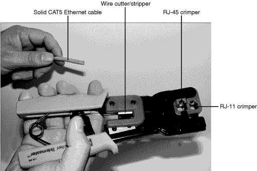
Ethernet cables and connectors aren’t expensive, but high-quality crimping tools (refer to Figure 5.11) can be more than $50. If you have friends or acquaintances who have already built ethernet cable, see whether you can borrow their tools, or buy them dinner and ask them over to help!
There are advantages to buying pre-assembled ethernet cable:
Availability—. You can buy ready-to-use CAT5/5e/6 Ethernet cable at office-supply, electronics, and discount stores. CAT5 is all you need for a 10/100 Ethernet network, but 5e and 6 provide higher signal quality.
Color-coding—. You can use a different cable color for each station on the network: blue, red, gray, black, purple, clear, and others.
Snagless connectors—. Almost all pre-assembled ethernet cables feature a cover over the locking tab on each end of the cable. This so-called snagless boot helps prevent cable tangles and damage to the locking tab. See Figure 5.10.

Tip: Cable Too Short? Couplers to the Rescue
If your network cable is too short to reach a particular station but it’s difficult (or impossible) to rerun a longer cable, buy an inline coupler. An inline coupler (Figure 5.10) connects to the end of one network cable and enables another cable to be plugged into the other end. Make sure the coupler is CAT5 compatible; some older couplers support CAT3 (10Mbps) signals only.
Of course, there are disadvantages to pre-assembled cable as well:
Cost per foot—. Short cables (under 25 feet) are very expensive. Expect to pay $2–$3/foot or more.
Difficulty in running cables through walls—. The connectors at the end of each cable make snaking the cable through walls or ceilings more difficult and require larger holes than raw cable does.
If you want to build your own ethernet cables, you should decide whether you want to build cables with standard ends (such as the ones shown in Figure 5.10) or if you want to build cables that connect to a wall plate.
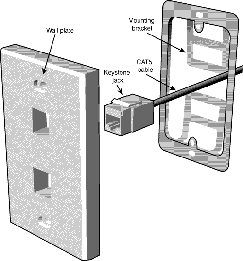
There are two ways you can use to connect cables to a wall plate. One method uses a keystone jack, which is an RJ-45 port that fits into a wall plate. You wire one end of the cable directly into the keystone jack. The other end of the cable can be wired into another keystone jack or can use a standard RJ-45 connector. An RJ-45 patch cable from a network adapter plugs into the keystone jack. The other method uses a wall plate that uses a snap-in coupler. The coupler works like the in-line coupler shown in Figure 5.10, enabling you to use standard RJ-45 connectors to build all of your cables.
Whether you use a keystone jack/wall plate assembly or a snap-in coupler/wall plate assembly, using a wall plate provides a more professional look to your network, but it also requires you to cut a hole in the wall. Table 5.3 breaks down the supplies needed for each type of cable, and Table 5.4 lists the tools needed for each type of cable.
Table 5.3. Supplies Needed for Building Ethernet Cables
Quantity Needed | Connection Type | Options | Notes | Refer to Figure # | |
|---|---|---|---|---|---|
Bulk Ethernet cable | 250 feet or longer | All | Color, type (solid or stranded) | Solid is stiffer and thus easier to run through walls. | |
RJ-45 standard connectors | Two per cable (one at each end) for standard cables; one per cable for keystone cable | Standard, in-line coupler | Snagless connector cover | Snagless connector cover should be color-matched to cable color. | |
RJ-45 keystone jack[1] | One per each end of cable | Keystone, in-line coupler | — | 8-wire keystone jacks work with RJ-45.[2] | |
Wall plate with keystone jack or snap-in coupler | One per each end of cable | Keystone, snap-in coupler | Number of ports (1–6) | Wall plate can also support RJ-11 telephone, RG-6 cable TV, and so on. | |
Mounting bracket | One per wall plate | Keystone, snap-in coupler | Match size of wall plate | Enables mounting of keystone jacks with wall plate without a wall box | |
Wall box | One per wall plate if mounting bracket is not used | Keystone, snap-in coupler | Match size of wall plate | Enables mounting of keystone jacks with wall plate to a stud | — |
[1] These figures show wall plates with keystone jacks. [2] 8-wire keystone jacks work with RJ-45. Do not try to use 2-wire, 4-wire, or 6-wire keystone jacks. Those types are used with RJ-11 telephone cable. | |||||
Table 5.4. Tools Needed for Building Ethernet Cables
Item | Connection Type | Notes | Refer to Figure # |
|---|---|---|---|
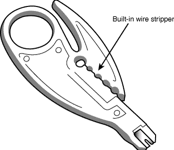
Crimper | Standard | Models with RJ-45 and RJ-11 crimps can also build telephone cables. Models with integrated wire stripper can be used to prepare wire for use. Creates more durable and reliable cables than pliers. | |
Punchdown tool | Keystone | Punches wire pairs into the keystone jack | |
Utility knife | Both | Strips outer jacket and wire pairs | |
Wire fish | Both | Pushes unfinished cable through walls and along studs | |
Diagonal cutters | Both | Cuts cable and trims wire pairs to correct lengths |


Tip: Fix It, Don’t Toss It!
You can also use some of the tools and supplies shown in Tables 5.3 and 5.4 and their companion figures to repair CAT5/5e/6 cables with broken connectors. Bent or broken locking tabs are the most frequent type of connector damage.
Whether you’re building a new ethernet cable from components or replacing a broken connector, the process works like this:
Run the cable from the switch or router to the location where you plan to place the computer or device. See “Hiding Your Cables,” p. 122, this chapter, for details.
Allow a couple of feet of additional cable for slack at each end. Make sure your cable run is no more than 100 meters (about 328 feet).
Cut off the end of the cable or the broken connector with a diagonal cutter (refer to Figure 5.18). Make sure the cut is straight.
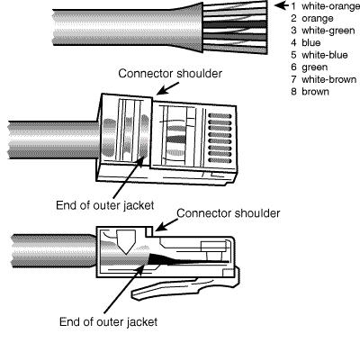
Measure and mark slightly more than one-half inch from the end of the cable. The outer jacket of this cable is removed in the next step.
Use a utility knife to remove the outer jacket of the cable with the utility knife or wire stripper, as marked in step 4 (refer to Figure 5.16).
Check the wire pairs for nicks or cuts. Redo steps 3–5 if any nicks or cuts are noticed.
Arrange the wires to match the EIA 568B standard as shown in Table 5.5 and in Figure 5.19.
Flatten the cable slightly.
Trim the wires so that they are slightly less than one-half inch longer than the outer wire jacket.
Push on the RJ-45 connector with the locking tab facing away from you until the end of the outer jacket is lined up with the shoulder of the connector. Figure 5.19 shows the top and profile view of a typical cable before and after the RJ-45 connector is inserted.
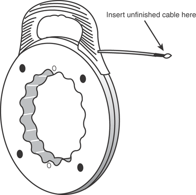
After inspecting the wire pairs and the position of the outer jacket, insert the end of the cable into the RJ-45 crimper (Figure 5.20).
Squeeze the crimper handle tightly (using both hands if necessary) to crimp the outer jacket and wire pairs in place.


If you use wall plates with snap-in couplers, use this same method to build your cables. Connect the wall-mounted cable connector to the inside end of the coupler, snap it into the wall plate, and use the mounting bracket described in the next section to fasten the wall plate to the wall. Connect a standard RJ-45 cable from the network adapter to the outside end of the coupler to finish the job.
If you want to put your cable in the wall and don’t want to use snap-in couplers, a keystone jack enables you to create the most elegant installation possible. After the keystone jack is installed, you run a short CAT5/5e/6 patch cable to the jack in the wall to make your connection.
Instead of using a male RJ-45 connector, a keystone jack assembly for home and small office environments uses a female RJ-45 connector, a wire holder known as a keystone plug (packaged with the keystone jack), a wall plate (buy the same brand as the keystone jack to avoid compatibility problems), and either a wall box or a mounting bracket. The mounting bracket’s bendable tabs enable the assembly to be secured to existing drywall.
To build the cable, follow steps 1–9 in the preceding section. Then, continue with the following:
Insert each wire into the keystone plug according to the EIA 568B standard listed in Table 5.5. Use your hands or the punchdown tool.
After the wires are inserted into the keystone plug, make sure the keystone plug and keystone jack resemble those shown in Figure 5.21.
Snap the keystone plug into the keystone jack (Figure 5.22).
Snap the keystone jack/plug assembly into the rear of the wall plate.
Connect other cables desired (telephone, coaxial, and so forth) to the appropriate ports in the wall plate.
Screw the wall plate into the wall box or mounting bracket already attached to the wall after you test the installation.


There are a variety of ways to make ethernet cable less obtrusive. Some of the methods you can use include
Which one is right for you?
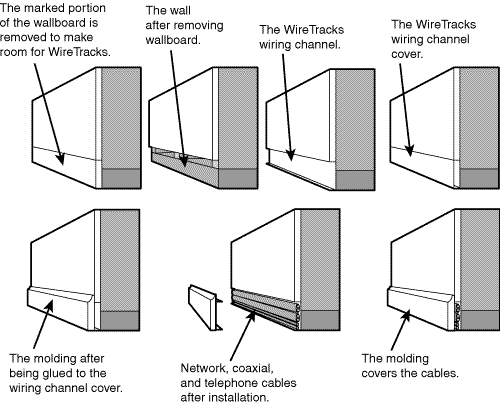
Wire-management systems can be built in to new construction, retrofitted behind the baseboards of existing baseboards, or attached to the sides of existing walls. External wire-management systems are also known as cable raceways. When repainted to match the wall, cable raceways harmonize with your existing décor. Wire-management systems can reduce the cabling costs of your network by enabling you to use shorter cable lengths, but the overall cost of your network is higher because of the cost of the wire-management solution you choose. Figure 5.23 shows how the WireTracks wire management system can be retrofitted to an existing room.
Running cables behind furniture or along existing baseboards, windows, and doorframes can increase the costs of your network because of the longer cable runs required. However, this is the easiest way to install network cable in an existing home or office.
Running cables through walls provides the shortest possible cable runs, but it also requires you to use unfinished cable and add connectors after it is installed. You can run the cable directly out of the wall to your device. However, if you want to create a more finished installation, you can connect your cable to a keystone jack and snap it into a wall box as described in the previous section. Then, you can use a short patch cable between your device and the wall box.
As Figure 5.7 shows, each station on a 10/100 Ethernet network connects to a switch. If your computers and other devices are in the same room or nearby rooms and you can hide the cable behind furniture or run it along baseboards, you might be satisfied to buy appropriate lengths of pre-built cables to run between each device and the switch. However, if you are building a home network that will have stations in several rooms in your home or have stations on two or more floors, how you buy and how you route your cabling can become critical issues.
Note: Tracking Down Wire-Management Systems
Some of the leading vendors for wire-management systems include
WireTracks (www.wiretracks.com)
LanShack (www.lanshack.com; also sells bundled network, coax, and fiber-optic cables)
HomeTech (www.hometech.com/techwire/wiremgmt.html)
CableOrganizer (http://cableorganizer.com/)
Most of these vendors also sell bulk network cable, cable-building tools, and other supplies you will find useful.
Whether you decide to buy pre-assembled cables or build your own, keep these basic rules in mind:
Keep network cables away from interference sources such as fluorescent lights, electric motors, and so on. The cables used by ethernet are sometimes referred to as unshielded twisted pair (UTP) cables, and that lack of shielding can lead to transmission problems if you don’t route them properly.
Keep network cables off the floor if possible, or protect them if they run across the floor. Network cables are vulnerable to crush damage (the wire pairs inside the outer jacket are made of very fine wire). You can use cable runners to protect network cable if you need to run it across the floor. However, it’s better to run cable around the doorframe if possible.
Color-code or mark your cables so you know which cable goes to a particular system. If you buy pre-built cables, you can use different colors for this purpose. Otherwise, you can use a label-maker.
You can run UTP Ethernet cable up to 100 meters (more than 300 feet) between a switch and a network client (PC or device). If you need a longer run, run a cable from one LAN port on the original switch to the uplink port on the remote switch, and then connect additional computers to the remote switch’s LAN ports. Refer to Figure 5.9.
Tip: Reducing Your Cable Runs and Avoiding Headaches
If you have two or more stations that are close to each other but are a long distance away from the switch, consider installing a switch in a convenient location to both systems and run your cables to the switch. Then, run a single cable between the switch and the central switch or router.
As you can see from the preceding sections, one of the most challenging parts of a wired ethernet network is the wiring itself. As you will learn in Chapter 6, “Installing and Configuring a Wi-Fi Network,” you can build a network that mixes Wi-Fi (wireless ethernet) and wired ethernet as one method for bridging longer distances. However, you can also use the existing telephone and power lines in your home to extend your home network beyond the convenient reach of wired ethernet.
HomePlug network adapters connect to a standard outlet and to your computer’s RJ-45 Ethernet port. HomePNA uses your phone lines to carry computer data as well as telephone calls; HomePNA adapters can connect to your computer’s USB port, PC Card slot, or PCI slots. As with HomePlug, you use a HomePNA adapter for each PC. How do HomePlug and HomePNA compare to each other and to 10/100 Ethernet? Table 5.6 lines up the facts for you.
Table 5.6. HomePlug, HomePNA, 10/100 Ethernet Compared
Network Type | Rated Speed | Typical USB Adapter Price | Wiring Type Used | Notes |
|---|---|---|---|---|
10/100 Ethernet | 100Mbps | $35 | CAT5/5e/6 UTP | Directly compatible with ethernet routers and switches |
HomePNA 2.0 | 10Mbps | $50 | Phoneline | Requires bridge to ethernet network |
HomePlug | 14Mbps | $60 | Powerline | Requires bridge to ethernet network |
Although the rated speeds of HomePNA 2.0 and HomePlug are far slower than 10/100 Ethernet, any of these standards are far faster than the fastest broadband Internet connections currently available (4Mbps cable modem).
Note: Adapter and Bridge?
Some vendors sell a single HomePlug device that functions as an adapter and an ethernet bridge, and others sell separate adapters and ethernet bridges. Be sure to check the specifications of the device you use.
To connect HomePlug stations to a wired ethernet network, connect a HomePlug-to-Ethernet bridge to a LAN port on your network’s switch or router. To connect HomePNA stations to a wired ethernet network, connect a HomePNA to ethernet bridge to an ethernet switch or router on your home network.
By incorporating an ethernet bridge in your home network, HomePlug or HomePNA and ethernet-based computers can connect with each other as part of a single network. Figure 5.24 illustrates a network with HomePlug and ethernet adapters and a HomePlug-to-Ethernet bridge.

After you connect your computers to the hub/switch/router, it’s time to configure them. In the past, network configuration has been a hair-pulling problem for many computer users. It required you to assign settings to each PC manually, and there was a high probability of network failure if you slipped up somewhere. However, starting with Windows 98, Microsoft Windows has included various versions of a home networking wizard, culminating with the Windows XP version.
Tip: Use the Windows XP Wizard for Easy Home Networking
If you have even one Windows XP CD handy, you can use its home networking wizard to configure your entire home network (if everybody uses Windows 9x/Me/XP). Windows XP’s home networking wizard is easier to use than previous versions.
Before we cover how to use the Windows XP Home Networking wizard, it’s important to understand the keys to successful home networking:
Make sure everybody is part of the same workgroup. With most versions of Windows, sharing printers or folders is more difficult if different workgroups are in use. Every network station needs to be configured to use the same workgroup name. HomePNA or HomePlug stations need to be connected via a bridge to the ethernet network.
Avoid duplicate computer names. Although all computers use the same workgroup name, each computer needs a unique name. You can use the location, the main user, the computer brand or model, and so on.
Make sure each computer has a unique IP address. The TCP/IP protocol is the main network protocol in use today. You can assign each computer its own IP address manually, but doing so requires you delve deep into the intricacies of IP address rules and regulations. It’s a lot simpler to use DHCP. A DHCP server is built in to virtually every router, enabling the router to provide a unique IP address to each computer on the network.
If all the computers on your network use Windows 98/Me/2000/XP and you’re not using your network to share Internet access or for noncomputer devices such as game systems or multimedia devices, you can use a feature built in to Windows called automatic private IP addressing (APIPA) to create a network without a router or other device to provide unique IP addresses. Each computer chooses its own unique IP address. For more information, see “Creating a Strictly Local Network with APIPA,” p. 138, this chapter.
If you already have a wired ethernet network but don’t have shared Internet access yet, you can provide shared Internet access to your network with this process:
Connect one computer directly to the broadband Internet device and configure it to connect to the device. Depending on the service, you might do this by running a configuration program from a CD or by setting the computer to receive its IP address automatically from the device.
Test the connection. If you can connect to the Internet, continue. If not, troubleshoot your connection. See Chapter 11, “Troubleshooting Your Home Network,” for details.
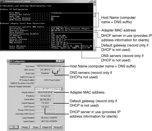
To use a router to share your Internet access, you need to duplicate the settings used by your computer in the router’s configuration. To view these settings, use Winipcfg (Windows 9x/Me) or IPConfig (Windows XP and Windows 2000). To run Winipcfg, click Start, Run, type
winipcfg, and click OK. Select your network adapter and click More. To run IPConfig, click Start, Run, typecmd, and click OK. Type IPConfig/all at the command prompt. TypeEXITto close the command prompt when you’re done. Refer to Figure 5.25.If DHCP is in use as shown here, all you need to record is the MAC address (adapter address) for the PC connected to the broadband Internet device.
Disconnect the computer from the broadband Internet device.
Connect the computer to one of the LAN ports on the router. Don’t connect the router with the rest of the network yet. Make sure you use a standard network cable, not a crossover cable (some broadband devices use a crossover cable to connect to the PC).
Note: Using DSL? Don’t Forget the PPPoE Information!
If you use a DSL connection to the Internet and you need to log in with a username and password to connect, your provider uses PPPoE. Be sure to record this information (not visible with IPConfig or WinIPCfg) as well so you can configure your router.
Turn on the router.
Restart your computer.
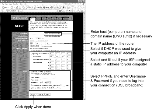
Open your web browser and enter the IP address of your router (http://xxx.xxx.xxx.xxx). See Figure 5.26.
Enter the password provided with the router to log in.
Configure the router’s WAN settings to use the same settings as the computer (Figure 5.26).
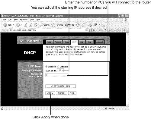
Configure the router’s DHCP settings to provide a dynamic IP address to each computer on the network (Figure 5.27). Don’t forget to include computers that are connected through bridges or external switches or hubs.
Clone the MAC address of the computer originally connected to the Internet to the router (Figure 5.28).
Tip: Connecting to Your Router
If you get an error message in step 10 instead of the router sign-on screen, your computer is probably using an IP address that is not in the same range as the IP address used by the router. For example, if your router has an IP address of 192.168.1.1, your computer must use an IP address of 192.168.1.x (x = 0, 2-254) to connect to it. Run IPConfig or Winipcfg again to see the current IP address of your computer. If your computer’s IP address starts with 169., or is otherwise not in the same range of numbers, set the IP address manually. See “Manual IP Address Configuration,” p. 322, Chapter 11.
Run a cable from the router’s WAN port to the ethernet port on the broadband Internet access device. To continue the process, see “Using the Windows XP Network Setup Wizard” below.
Connect each computer’s network cable to a LAN port on the router. If you need additional ports, connect a switch to the Uplink port on the router. If you use the Uplink port, it takes over the connection used by the LAN port next to it. Thus, you can use all the LAN ports or all but the last LAN port and the Uplink port.

After the router has been configured to provide IP addresses for the computer, it’s time to configure each computer to use the network. The easiest way to do this is with the Windows XP Network Setup Wizard. To start the wizard on a system running Windows XP, click Start, All Programs, Accessories, Communications, Network Setup Wizard.
You can also use the Windows XP CD to run the wizard on other systems running Windows 98/98SE or Windows Me. To do so, insert the Windows XP CD. If the Windows XP Welcome screen is not displayed after you insert the Windows XP CD, open the Setup.exe file in Windows Explorer. From the Windows XP Welcome screen, click Perform Additional Tasks. Click Set up a home or small office network to start the wizard.
If you use a preinstalled version of Windows XP, you can also start the wizard this way: Click Start, All Programs, Accessories, Communications, Network Setup Wizard. When you complete the Setup Wizard, you can make a floppy disk to run the Setup Wizard on systems that use other versions of Windows.
Tip: Why Clone?
Many broadband ISPs require you to provide the MAC address of your network adapter when you connect for the first time. By cloning your computer’s MAC address to the router, you don’t need to reregister your hardware with your ISP.
Before starting this process, connect each PC to a LAN port on the router or a port on a switch connected to the router:
Click Next at the opening screen, and click Next at the checklist screen.
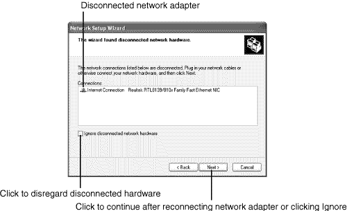
If you see a warning that some of your network hardware is disconnected, look at the network connection listed (Figure 5.29). If your ethernet port is listed, double-check your cable connections (including any dongles). Fix any loose or disconnected cables and click Next to continue. Windows XP considers IEEE-1394 (FireWire) ports to be network adapters. If your 1394 adapter is listed, click Ignore disconnected hardware and click Next to continue.
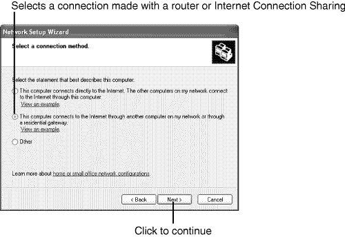
Click This computer connects to the Internet through another computer on my network or through a residential gateway (Figure 5.30). Click Next to continue.
Note: Don’t Like Wizards? D-I-Y Setup Is Also Available
If you don’t like Windows wizards, or you’re using a version of Windows (or another operating system) that doesn’t work with the Windows XP wizard, see “Configuring a Shared Connection Without a Network Wizard,” p. 137, this chapter.
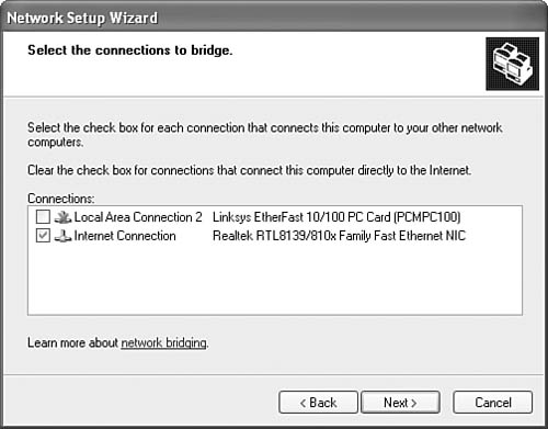
Click Let me choose my connections to the network (if prompted). Click Next to continue.
Clear all check marks except for the network interface card or port you are using (Figure 5.31). Click Next to continue.
Enter a description for the computer. Enter a unique name if the computer is not already named (Figure 5.32). Click Next to continue.
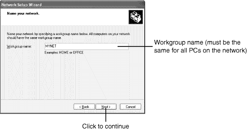
Enter the workgroup name you want to use (Figure 5.33); don’t use the default (MSHOME). Make sure you use the same workgroup name for all computers. Click Next to continue.
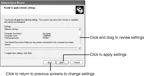
Scroll through the settings. Use Back to retrace your steps and make any corrections (Figure 5.34). Click Next to apply the settings and complete the process.
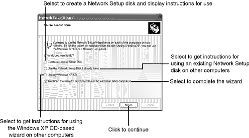
After you run the wizard, you can create a Network Setup Disk for use on other computers or choose other options (Figure 5.35). Click Next after selecting a setup option for other computers to get instructions for using or making a Network Setup Disk or using the Windows XP CD.
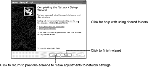
Click Finish to close the wizard, or click Back to change settings. Click the underlined links for more help with your network (Figure 5.36).
Remove the Windows XP CD or Network Setup Disk and reboot the computer. You should be able to access the Internet and use shared folders and printers after the computer restarts. See Chapter 8, “Home Networks at Work and School,” to learn how to use shared folders and printers.

Note: Share and Share Alike
By default, the Windows XP Network Setup Wizard shares the Shared Documents folder and any printers connected to the computer with the rest of the network. To share additional folders or printers installed after the wizard was run, or to stop sharing folders or printers, see Chapter 8.
Run the networking wizard on each computer, using a unique name for each computer, but the same network (workgroup) and connection options you used previously.
What if you’re not using Windows XP or just don’t like to use wizards? You can configure a network connection manually following this basic outline. Most steps are performed through the Network icon in the Control Panel:
Install the TCP/IP protocol if it is not already installed.
Configure the TCP/IP protocol to use a server-assigned IP address (the “server” is the router).
Install File and Printer Sharing on each computer with a printer or folder you want to share.
Create a unique name for each computer. In Windows 9x/Me, the computer name is listed on the Identification tab in the Network dialog. In Windows 2000/XP, the computer name is listed on the Computer Name tab in the System properties sheet. To change the name or workgroup, click the Change button.
Configure each computer to use the same workgroup name. In Windows 9x/Me, the workgroup name is on the Identification tab in the Network dialog. In Windows 2000/XP, the workgroup is listed on the Computer Name tab in the System properties sheet. To change the name or workgroup, click the Change button.
Connect each computer to the router.
Reboot each computer to achieve Internet access.
Windows 98 (but not Windows 95), Windows Me, Windows 2000, and Windows XP are designed to use IP addresses obtained in one of three ways:
Manually
From a DHCP server (such as a router)
Automatically using APIPA
Windows 98, Me, and 2000 also support an older network protocol called NetBEUI. Before Windows XP was introduced, I would have told you to use NetBEUI to create a home network that didn’t include Internet access. However, Windows XP doesn’t install NetBEUI automatically, doesn’t support it, and provides a complicated installation procedure if you want to use the NetBEUI drivers included “for troubleshooting” on the Windows XP CD. However, the biggest strikes against NetBEUI are that it doesn’t provide Internet access if you add a broadband connection and it’s very vulnerable to online attacks after you connect to the Internet.
So, if you’re looking for a Windows-only, local network today, say goodbye NetBEUI and hello APIPA. What is APIPA? APIPA is a way to create a TCP/IP network that supports local connections today and enables you to move easily to sharing a broadband Internet connection tomorrow. The only difference is that you can use a switch with an APIPA-based network instead of a router, because each computer creates its own IP address, instead of receiving it from a router or another device. Here’s the procedure:
Open the Network icon in Control Panel on each computer.
Install the TCP/IP protocol (if not already installed).
Configure the TCP/IP protocol to obtain an IP address automatically.
Configure each computer to use the workgroup name.
Create a unique name for each computer.
Install File and Printer Sharing on each computer with a printer or folder you want to share.
Connect the computer to the switch.
Reboot each computer. A message will indicate that automatic IP addressing is being used because a DHCP server is not available.
Select which resources you want to share (see Chapter 8 for details).
The beauty of an APIPA-based network is that you can easily swap the switch for a router with a built-in switch (or connect a separate router) later to share an Internet connection.
However, APIPA is not supported by all operating systems. Linux doesn’t support APIPA, nor do versions of MacOS prior to version 8.5. If you want to put computers using these operating systems on your home network, use a router even if you don’t have a broadband Internet connection yet. Use the router’s DHCP server to provide IP addresses to all devices configured to obtain an IP address automatically.
Similarly, some non-PC devices (print servers, media adapters, and so on) might not support APIPA either. If the device doesn’t support APIPA, it can’t generate its own IP addresses and must depend on a DHCP server to obtain an IP address. See the documentation for the device to determine whether APIPA is listed as a supported TCP/IP protocol.