
RF Characteristics
Abstract
This chapter presents the RF requirements that define the RF characteristics of both base stations and devices. Both an overview and further details of transmitter and receiver requirements are given, including how they are subdivided into conducted and radiated requirements.
Keywords
RF characteristics; RF requirements; soectrum flexibility; frequency range; radiated; conducted; BS types; BS classes; multistandard; multiband; non-contiguous
The RF characteristics of NR are strongly tied to the spectrum available for 5G as described in Chapter 3 and the spectrum flexibility required to operate in those spectrum allocations. While spectrum flexibility has been a cornerstone for previous generations of mobile systems, this becomes even more accentuated for NR. It consists of several components, including deployment in different-sized spectrum allocations and diverse frequency ranges, both in paired and unpaired frequency bands and with aggregation of different frequency allocations within and between different bands. NR will also have the capability to operate with mixed numerology on the same RF carrier and will have an even higher flexibility than LTE in terms of frequency domain scheduling and multiplexing of devices within a base station RF carrier. It is the use of OFDM in NR that gives flexibility both in terms of the size of the spectrum allocation needed and in the instantaneous transmission bandwidth used, and that enables frequency-domain scheduling.
Implementation of Active Antenna Systems (AAS) and multiple antennas in devices has been in use for LTE, but is taken one step further in NR, which will support massive MIMO and beam-forming applications both in existing bands and in the new mm-wave bands. Beyond the physical layer implications, this impacts the RF implementation in terms of filters, amplifiers, and all other RF components that are used to transmit and receive the signal and must be defined taking also the spectrum flexibility into account. These are further discussed in Chapter 19.
Note that for the purpose of defining RF characteristics, the physical representation of the gNB is called a base station (BS). A base station is defined with interfaces where the RF requirements are defined, either as conducted requirements at an antenna port or as radiated requirements over-the-air (OTA).
18.1 Spectrum Flexibility Implications
Spectrum flexibility was a fundamental requirement for LTE and it had major implications for how LTE was specified. The need for spectrum flexibility is even higher for NR, because of the diverse spectrum where NR needs to operate and the way the physical layer is designed to meet the key characteristics required for 5G. The following are some important aspects impacting how the RF characteristics are defined:
- • Diverse spectrum allocations: The spectrum used for 3G and 4G is already very diverse in terms of the sizes of the frequency of operation, bandwidth allocations, how they are arranged (paired and unpaired), and what the related regulation is. For NR it will be even more diverse, with the fundamental frequency varying from below 1 GHz up to 40–50 GHz and above; the maximum frequency presently under study in ITU-R is 86 GHz. The size of allocated bands where NR is to be deployed varies from 5 MHz to 3 GHz, with both paired and unpaired allocations, where the intention is to use some allocations as supplementary downlinks or uplinks together with other paired bands. The spectrum that is planned and under investigation to be used for 5G and the related operating bands defined for NR are described in Chapter 3.
- • Various spectrum block definitions: Within the diverse spectrum allocations, spectrum blocks will be assigned for NR deployment, usually through operator licenses. The exact frequency boundaries of the blocks can vary between countries and regions and it must be possible to place the RF carriers in positions where the blocks are used efficiently without wasting spectrum. This puts specific requirements on the channel raster to use for placing carriers.
- • LTE-NR coexistence: The LTE/NR coexistence in the same spectrum makes it possible to deploy NR with in-carrier coexistence in both uplink and downlink of existing LTE deployments. This is further described in Chapter 17. Since the coexisting NR and LTE carriers need to be subcarrier-aligned, this poses restrictions on the NR channel raster in order to align the placing of NR and LTE carriers.
- • Multiple and mixed numerologies: As described in Section 7.1, the transmission scheme for NR has a high flexibility and supports multiple numerologies with subcarrier spacings ranging from 15 to 240 kHz, with direct implications for the time and frequency domain structure. The subcarrier spacing has implications for the RF in terms of the roll-off of the transmitted spectrum, which impact the resulting guard bands that are needed between the transmitted resource blocks and the RF carrier edge defined for the purpose of defining RF requirements (see Section 18.3). NR also supports mixed numerologies on the same carrier, which has further RF impacts since the guard bands may need to be different at the two edges of the RF carrier.
- • Independent channel bandwidth definitions: NR devices in general do not receive or transmit using the full channel bandwidth of the BS but can be assigned what is called a bandwidth part (see Section 7.4). While the concept does not have any direct RF implications, it is important to note that BS and device channel bandwidth are defined independently and that the device bandwidth capability does not have to match the BS channel bandwidth.
- • Variation of duplex schemes: As shown in Section 7.2, a single frame structure is defined in NR that supports TDD, FDD, and half-duplex FDD. The duplex method is specifically defined for each operating band defined for NR as shown in Chapter 3. Some bands are also defined as supplementary downlink (SDL) or supplementary uplink (SUL) to be used in FDD operation. This is further described in Section 7.7.
Many of the frequency bands identified for deployment of NR are existing bands identified for IMT (see Chapter 3) and they may already have 2G, 3G, and/or 4G systems deployed. Many bands are also in some regions defined and regulated in a “technology-neutral” manner, which means that coexistence between different technologies is a requirement. The capability to operate in this wide range of bands for any mobile system, including NR, has direct implications for the RF requirements and how those are defined, in order to support the following:
- • Coexistence between operators in the same geographical area in the band: Operators in the same band may deploy NR or other IMT technologies, such as LTE, UTRA, or GSM/EDGE. There may in some cases also be non-IMT technologies. Such coexistence requirements are to a large extent developed within 3GPP, but there may also be regional requirements defined by regulatory bodies in certain cases.
- • Co-location of base-station equipment between operators: There are in many cases limitations to where base-station equipment can be deployed. Often, sites must be shared between operators or an operator will deploy multiple technologies in one site. This puts additional requirements on both base-station receivers and transmitters to operate in close proximity to other base stations.
- • Coexistence with services in adjacent frequency bands and across country borders: The use of the RF spectrum is regulated through complex international agreements, involving many interests. There will therefore be requirements for coordination between operators in different countries and for coexistence with services in adjacent frequency bands. Most of these are defined in different regulatory bodies. In some cases, the regulators request that 3GPP includes such coexistence limits in the 3GPP specifications.
- • Coexistence between operators of TDD systems in the same band is in general provided by inter-operator synchronization, in order to avoid interference between downlink and uplink transmissions of different operators. This means that all operators need to have the same downlink/uplink configurations and frame synchronization, which is not in itself an RF requirement, but it is implicitly assumed in the 3GPP specifications. RF requirements for unsynchronized systems become much stricter.
- • Release-independent frequency-band principles: Frequency bands are defined regionally, and new bands are added continuously for each generation of mobile systems. This means that every new release of 3GPP specifications will have new bands added. Through the “release independence” principle, it is possible to design devices based on an early release of 3GPP specifications that support a frequency band added in a later release. The first set of NR bands (see Chapter 3) is defined in release 15 and additional bands will be added in a release-independent way.
- • Aggregation of spectrum allocations: Operators of mobile systems have quite diverse spectrum allocations, which in many cases do not consist of a block that easily fits exactly within one carrier. The allocation may even be non-contiguous, consisting of multiple blocks spread out in a band or in multiple bands. For these scenarios, the NR specifications supports carrier aggregation, where multiple carriers within a band, or in multiple bands, can be combined to create larger transmission bandwidths.
18.2 RF Requirements in Different Frequency Ranges
As discussed above and in Chapter 3, there will be a very wide range of diverse spectrum allocations where NR can operate. The allocations vary in block size, channel bandwidth and duplex spacing supported, but what really differentiates NR from previous generations is the wide frequency range over which requirements need to be defined, where not only the requirement limits but also the definitions and conformance testing aspects may be quite different at different frequencies. Measurement equipment, such as spectrum analyzers, becomes more complex and expensive at higher frequencies and for the highest frequencies considered, including the harmonics of the highest possible carrier frequencies, requirements may not even be possible to test in a reasonable way.
For this reason, the RF requirements for both devices and base stations are divided into frequency ranges (FRs), where presently two are defined (FR1 and FR2) in 3GPP release 15 as shown in Table 18.1. The frequency range concept is not intended to be static. If new NR band(s) are added that are outside the existing frequency ranges, one of them could be extended to cover the new band(s) if the requirements will align well with that range. If there are large differences compared to existing FR, a new frequency range could be defined for the new band.
Table 18.1
| Frequency Range Designation | Corresponding Frequency Range |
|---|---|
| Frequency range 1 (FR1) | 450–6,000 MHz |
| Frequency range 2 (FR2) | 24,250–52,600 MHz |
The frequency ranges are also illustrated in Fig. 18.1 on a logarithmic scale, where the related bands identified for IMT (in at least one region) are shown. FR1 starts at 450 MHz at the first IMT allocation and ends at 6 GHz. FR2 covers a subset of the bands that are presently under study for IMT identification in the ITU-R (see Section 3.1). The subset ends at 52.6 GHz, which is the highest frequency within the scope of the specification work in 3GPP release 15.

All existing LTE bands are within FR1 and NR is expected to coexist with LTE and previous generations of systems in many of the FR1 bands. It is only in what is often referred to as the “mid bands” around 3.5 GHz (in fact spanning 3.3–5 GHz) that NR will to a larger extent be deployed in a “new” spectrum, that is a spectrum previously not exploited for mobile services. FR2 covers a part of what is often referred to as the mm-wave band (strictly, mm-wave starts at 30 GHz with 10 mm wavelength). At such high frequencies compared to FR1, propagation properties are different, with less diffraction, higher penetration losses, and in general higher path losses. This can be compensated for by having more antenna elements both at the transmitter and receiver, to be used for narrower antenna beams with higher gain and for massive MIMO. This gives overall different coexistence properties and therefore leads to different RF requirements for coexistence. mm-wave RF implementation for FR2 bands will also have different complexity and performance compared to FR1 bands, impacting all components including A/D and D/A converters, LO generation, PA efficiently, filtering, etc. This is further discussed in Chapter 19.
18.3 Channel Bandwidth and Spectrum Utilization
The operating bands defined for NR have a very large variation in bandwidth, as shown in Chapter 3. The spectrum available for uplink or downlink can be as small as 5 MHz in some LTE re-farming bands, while it is up to 900 MHz in “new” bands for NR in frequency range 1, and up to several GHz in frequency range 2. The spectrum blocks available for a single operator will often be smaller than this. Furthermore, the migration to NR in operating bands currently used for other radio-access technologies such as LTE, must often take place gradually to ensure that a sufficient amount of spectrum remains to support the existing users. Thus, the amount of spectrum that can initially be migrated to NR can be relatively small but may then gradually increase. The variation of the size of spectrum blocks and possible spectrum scenarios implies a requirement for very high spectrum flexibility for NR in terms of the transmission bandwidths supported.
The fundamental bandwidth of an NR carrier is called the channel bandwidth (BWChannel) and is a fundamental parameter for defining most of the NR RF requirements. The spectrum flexibility requirement points out the need for NR to be scalable in the frequency domain over a large range. In order to limit implementation complexity, only a limited set of bandwidths is defined in the RF specifications. A range of channel bandwidths from 5 to 400 MHz is supported.
The bandwidth of a carrier is related to the spectrum utilization, which is the fraction of a channel bandwidth occupied by the physical resource blocks. In LTE, the maximum spectrum utilization was 90%, but a higher number has been targeted for NR to achieve a higher spectrum efficiency. Considerations however must be taken for the numerology (subcarrier spacing), which impacts the OFDM waveform roll-off, and for the implementation of filtering and windowing solutions. In addition, spectrum utilization is related to the achievable error vector magnitude (EVM) and transmitter unwanted emissions, and also to receiver performance including adjacent channel selectivity (ACS). The spectrum utilization is specified as a maximum number of physical resource blocks, NRB, which will be the maximum possible transmission bandwidth configuration, defined separately for each possible channel bandwidth.
What the spectrum utilization ultimately defines is a guard band at each edge of the RF carrier, as shown in Fig. 18.2. Outside of the guard band and thereby outside the RF channel bandwidth, the “external” RF requirements such as unwanted emissions are defined, while only requirements on the actual RF carrier such as EVM are defined inside. For a channel bandwidth BWChannel, the guard band will be
(18.1)
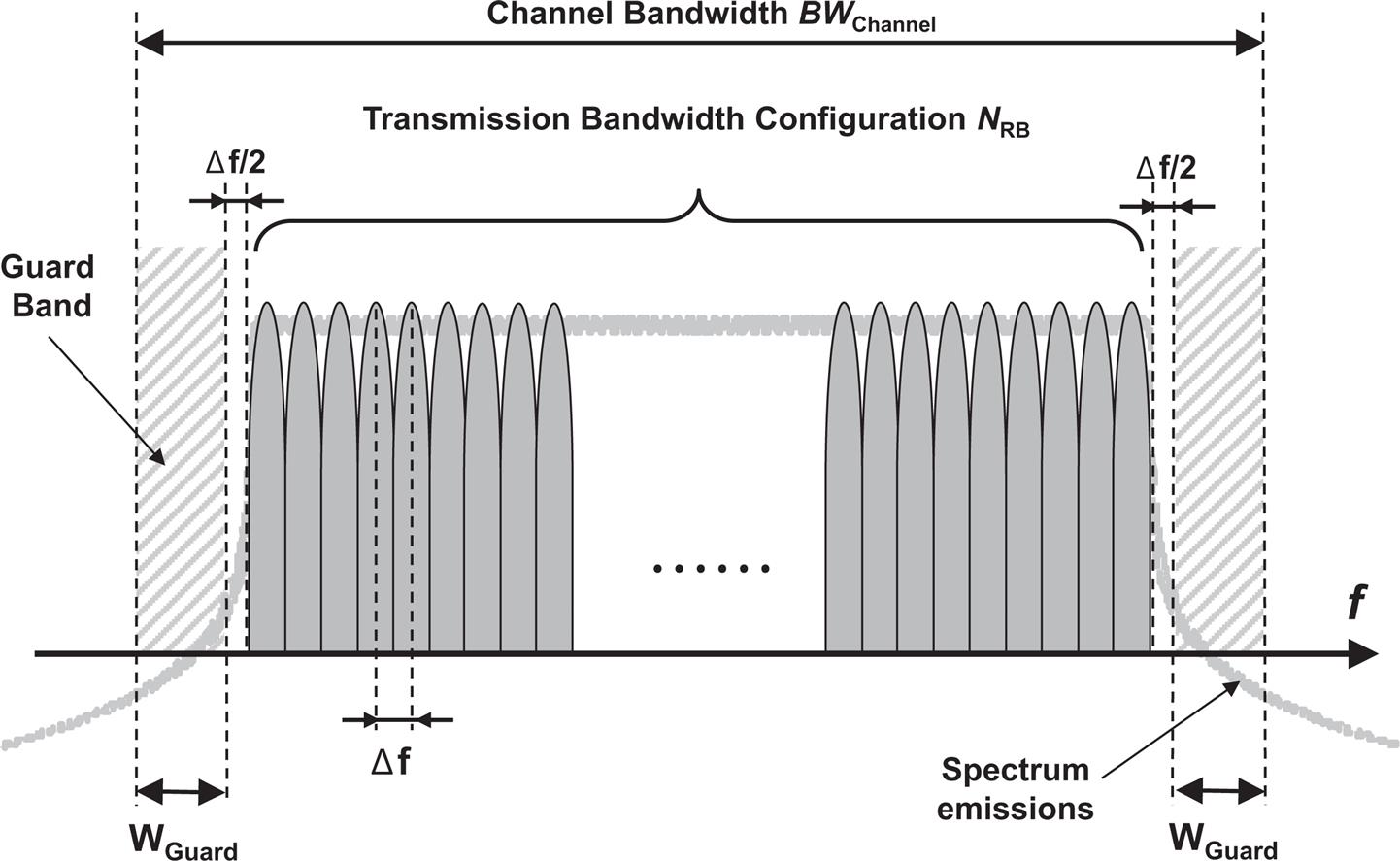
where NRB is the maximum number of resource blocks possible and Δf is the subcarrier spacing. The extra Δf/2 guard applied on each side of the carrier is due to the relation to the RF channel raster, which has a subcarrier-based granularity and is defined independently of the actual spectrum blocks. It may therefore not be possible to place a carrier exactly in the center of a spectrum block and an extra guard will be required to make sure RF requirements can be met.
As shown in Eq. (18.1), the guard band and thereby the spectrum utilization will depend on the numerology applied. As described in Section 7.3, different bandwidths will be possible depending on the subcarrier spacing of the numerology, since the maximum value for NRB is 275. In order to have reasonable spectrum utilization, values of NRB below 11 are not used either. The result is a range of possible channel bandwidths and corresponding spectrum utilization numbers defined for NR, as shown in Table 18.2. Note that the subcarrier spacing used differs between frequency ranges 1 and 2. The spectrum utilization expressed as a fraction is up to 98% for the widest channel bandwidths and it is above 90% for all cases, except for the smaller bandwidths, where NRB≤25.
Table 18.2

Since the channel bandwidth is defined independently for base stations and devices (see above and in Section 7.4), the actual channel bandwidths that are supported by the base station and device specifications will also be different. For a specific bandwidth, the supported spectrum utilization is however the same for base station and device, if the combination of bandwidth and subcarrier spacing is supported by both.
18.4 Overall Structure of Device RF Requirements
The differences in coexistence properties and implementation between FR1 and FR2 means that device RF requirements for NR are defined separately for FR1 and FR2. For a more detailed discussion of the implementation aspects in FR2 using mm-wave technology for devices and base stations, see Chapter 19.
For LTE and previous generations, RF requirements have in general been specified as conducted requirements that are defined and measured at an antenna connector. Since antennas are normally not detachable on a device, this is done at an antenna test port. Device requirements in FR1 are defined in this way.
With the higher number of antenna elements for operation in FR2 and the high level of integration expected when using mm-wave technology, conducted requirements are no longer seen as feasible. FR2 will therefore be specified with radiated requirements and testing will have to be done OTA. While this is an extra challenge when defining requirements, in particular for testing, it is seen as a necessity for FR2.
There will also be a set of device requirements for interworking with other radios within the same device. This concerns primarily interworking with E-UTRA for non-standalone (NSA) operation and interworking between FR1 and FR2 radios for carrier aggregation.
Finally, there is a set of device performance requirements, which set the baseband demodulation performance of physical channels of the device receiver across a range of conditions, including propagation in different environments.
Because of the differences between the different types of requirements, the specification for device RF characteristics is separated into four different parts, where the device is called user equipment (UE) in 3GPP specifications:
The conducted RF requirements for FR1 are described in Sections 18.6–18.11.
18.5 Overall Structure of Base-Station RF Requirements
18.5.1 Conducted and Radiated RF Requirements for NR BS
For the continuing evolution of mobile systems, AAS have an increasing importance. While there were several attempts to develop and deploy base stations with passive antenna arrays of different kinds for many years, there have been no specific RF requirements associated with such antenna systems. With RF requirements in general defined at the base station RF antenna connector, the antennas have also not been seen as part of the base station, at least not from a standardization point of view.
Requirements specified at an antenna connector are referred to as conducted requirements, usually defined as a power level (absolute or relative) measured at the antenna connector. Most emission limits in regulation are defined as conducted requirements. An alternative way is to define a radiated requirement, which is assessed including the antenna, often accounting for the antenna gain in a specific direction. Radiated requirements demand more complex OTA test procedures, using for example an anechoic chamber. With OTA testing, the spatial characteristics of the whole BS, including the antenna system, can be assessed.
For base stations with AAS, where the active parts of the transmitter and receiver may be an integral part of the antenna system, it is not always suitable to maintain the traditional definition of requirements at the antenna connector. For this purpose, 3GPP developed RF requirements in release 13 for AAS base stations in a set of separate RF specifications that are applicable to both LTE and UTRA equipment.
For NR, radiated RF requirements and OTA testing will be a part of the specifications from the start, both in FR1 and FR2. Much of the work from AAS has therefore been taken directly into the NR specifications. The term AAS as such is not used within the NR base-station RF specification [4], however requirements are instead defined for different BS types.
The AAS BS requirements are based on a generalized AAS BS radio architecture, as shown in Fig. 18.3. The architecture consists of a transceiver unit array that is connected to a composite antenna that contains a radio distribution network and an antenna array. The transceiver unit array contains multiple transmitter and receiver units. These are connected to the composite antenna through a number of connectors on the transceiver array boundary (TAB). These TAB connectors correspond to the antenna connectors on a non-AAS base station and serve as a reference point for conducted requirements. The radio distribution network is passive and distributes the transmitter outputs to the corresponding antenna elements and vice versa for the receiver inputs. Note that the actual implementation of an AAS BS may look different in terms of physical location of the different parts, array geometry, type of antenna elements used, etc.
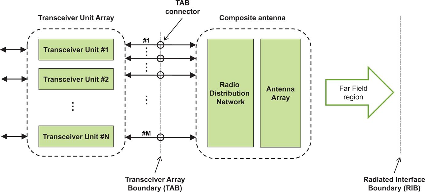
Based on the architecture in Fig. 18.3, there are two types of requirements:
- • Conducted requirements are defined for each RF characteristic at an individual or a group of TAB connectors. The conducted requirements are defined in such a way that they are in a sense “equivalent” to the corresponding conducted requirement for a non-AAS base station, that is, the performance of the system or the impact on other systems is expected to be the same.
- • Radiated requirements are defined OTA in the far field of the antenna system. Since the spatial direction becomes relevant in this case, it is detailed for each requirement how it applies. Radiated requirements are defined with reference to a radiated interface boundary (RIB), somewhere in the far-field region.
18.5.2 BS Types in Different Frequency Ranges for NR
A number of different base-station design possibilities have to be considered for the RF requirements. First in FR1, there are base stations built in a way similar to “classical” 3G and 4G base stations with antenna connectors through which external antennas are connected. Then we have base stations with AAS, but where antenna connectors can still be accessed for definition and testing of some RF requirements. Finally, we have base stations with highly integrated antenna systems where all requirements must be assessed OTA, since there are no antenna connectors. It is assumed that in FR2 where mm-wave technology is used for implementation of the antenna systems, only the latter type of base station needs to be specified.
3GPP has defined four base-station types based on the above assumptions, with reference to the architecture defined above in Fig. 18.3:
- • BS type 1-C: NR base station operating in FR1, specified only with conducted requirements defined at individual antenna connectors.
- • BS type 1-O: NR base station operating in FR1, specified only with conducted (OTA) requirements defined at the RIB.
- • BS type 1-H: NR base station operating at FR1, specified with a “hybrid” set of requirements consisting of both conducted requirements defined at individual TAB connectors and some OTA requirements defined at the RIB.
- • BS type 2-O: NR base station operating in FR2, specified only with conducted (OTA) requirements defined at the RIB.
BS type 1-C has requirements defined in the same way as for UTRA or LTE conducted requirements. These are described in Sections 18.6–18.11.
BS type 1-H corresponds to the first type of AAS base stations specified for LTE/UTRA in 3GPP Release 13, where two radiated requirements are defined (radiated transmit power and OTA sensitivity), while all others are defined as conducted requirements, as described in Sections 18.6–18.11. Many conducted requirements, such as unwanted emission limits, are for BS type 1-H defined in two steps. First a basic limit is defined, which is identical to the conducted limit at an individual antenna connector for BS type 1-C and thereby equivalent to the limit at a TAB connector for BS type 1-H. In a second step, the basic limit is converted to a radiated limit at the RIB through a scaling factor based on the number of active transmitter units. The scaling is capped at a maximum of 8 (9 dB), which is the maximum number of antenna elements used in defining certain regulatory limits. Note that the maximum scaling may vary depending on regional regulation.
BS type 1-O and BS type 2-O have all requirements defined as radiated. BS type 1-O has many requirements defined with reference to the corresponding FR1 conducted requirements, where unwanted emission limits also have a scaling applied as for BS type 1-H. The overall differences in coexistence properties and implementation between FR1 and FR2 mean that BS type 2-O has separate FR2 requirements defined that in many cases are different from the FR1 requirements for BS type 1-O.
An overview of the radiated requirements used for BS types 1-O and 2-O, and to some extent for BS type 1-H, is given in Section 18.12.
18.6 Overview of Conducted RF Requirements for NR
The RF requirements define the receiver and transmitter RF characteristics of a base station or device. The base station is the physical node that transmits and receives RF signals on one or more antenna connectors. Note that an NR base station is not the same thing as a gNB, which is the corresponding logical node in the radio-access network (see Chapter 6). The device is denoted UE in all RF specifications. Conducted RF requirements are defined for operating bands in FR1, while only radiated (OTA) requirements are defined for FR2 (see Section 18.12).
The set of conducted RF requirements defined for NR is fundamentally the same as those defined for LTE or any other radio system. Some requirements are also based on regulatory requirements and are more concerned with the frequency band of operation and/or the place where the system is deployed, than with the type of system.
What is particular to NR is the flexible channel bandwidths and multiple numerologies of the system, which makes some requirements more complex to define. These properties have special implications for the transmitter requirements on unwanted emissions, where the definition of the limits in international regulation depend on the channel bandwidth. Such limits are harder to define for a system where the base station may operate with multiple channel bandwidths and where the device may vary its channel bandwidth of operation. The properties of the flexible OFDM-based physical layer also have implications for specifying the transmitter modulation quality and how to define the receiver selectivity and blocking requirements. Note that the channel bandwidth in general is different for the BS and the device as discussed in Section 18.3.
The type of transmitter requirements defined for the device is very similar to what is defined for the base station, and the definitions of the requirements are often similar. The output power levels are, however, considerably lower for a device, while the restrictions on the device implementation are much higher. There is tight pressure on cost and complexity for all telecommunications equipment, but this is much more pronounced for devices, due to the scale of the total market, being close to two billion devices per year. In cases where there are differences in how requirements are defined between device and base station, they are treated separately in this chapter.
The detailed background of the conducted RF requirements for NR is described in Refs. [74] and [75]. The conducted RF requirements for the base station are specified in Ref. [4] and for the device in Ref. [5]. The RF requirements are divided into transmitter and receiver characteristics. There are also performance characteristics for base stations and devices that define the receiver baseband performance for all physical channels under different propagation conditions. These are not strictly RF requirements, though the performance will also depend on the RF to some extent.
Each RF requirement has a corresponding test defined in the NR test specifications for the base station and the device. These specifications define the test setup, test procedure, test signals, test tolerances, etc. needed to show compliance with the RF and performance requirements.
18.6.1 Conducted Transmitter Characteristics
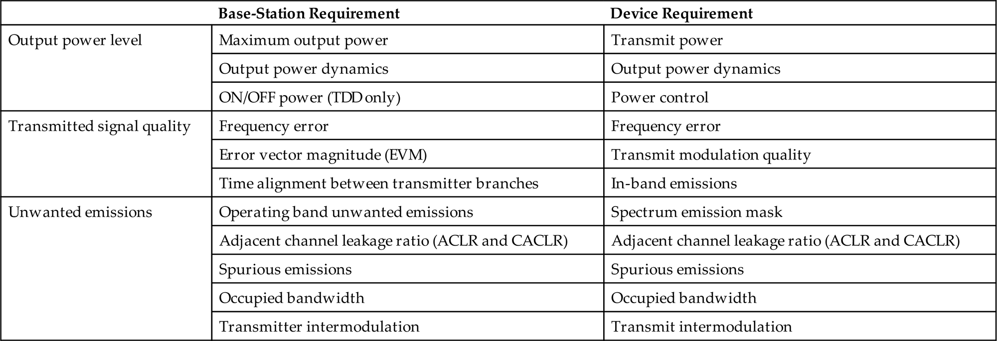
The transmitter characteristics define RF requirements for the wanted signal transmitted from the device and the base station, but also for the unavoidable unwanted emissions outside the transmitted carrier(s). The requirements are fundamentally specified in three parts:
- • Output power level requirements set limits for the maximum allowed transmitted power, for the dynamic variation of the power level, and in some cases for the transmitter OFF state;
- • Transmitted signal quality requirements define the “purity” of the transmitted signal and also the relation between multiple transmitter branches;
- • Unwanted emissions requirements set limits to all emissions outside the transmitted carrier(s) and are tightly coupled to regulatory requirements and coexistence with other systems.
A list of the device and base-station transmitter characteristics arranged according to the three parts defined above is shown in Table 18.3. A more detailed description of the specific requirements can be found later in this chapter.
Table 18.3
18.6.2 Conducted Receiver Characteristics
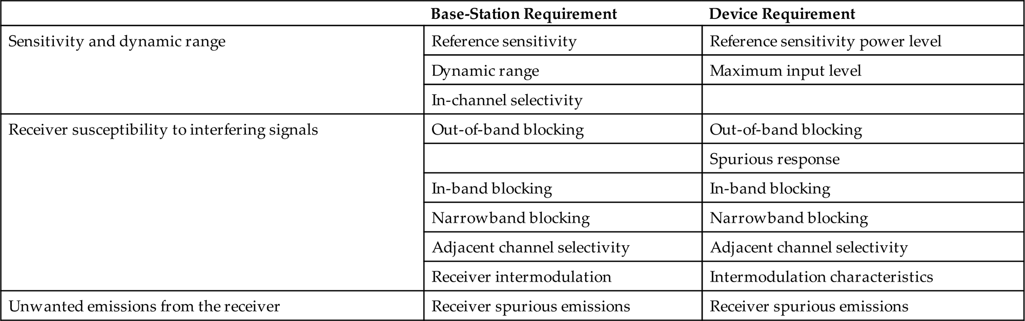
The set of receiver requirements for NR is quite similar to what is defined for other systems such as LTE and UTRA. The receiver characteristics are fundamentally specified in three parts:
A list of the device and base-station receiver characteristics arranged according to the three parts defined above is shown in Table 18.4. A more detailed description of each requirement can be found later in this chapter.
Table 18.4
18.6.3 Regional Requirements
There are a number of regional variations to the RF requirements and their application. The variations originate in different regional and local regulations of the spectrum and its use. The most obvious regional variation is the different frequency bands and their use, as discussed above. Many of the regional RF requirements are also tied to specific frequency bands.
When there is a regional requirement on, for example, spurious emissions, this requirement should be reflected in the 3GPP specifications. For the base station it is entered as an optional requirement and is marked as “regional.” For the device, the same procedure is not possible, since a device may roam between different regions and will therefore have to fulfill all regional requirements that are tied to an operating band in the regions where the band is used. For NR (and also for LTE), this becomes more complex than for UTRA, since there is an additional variation in the transmitter (and receiver) bandwidth used, making some regional requirements difficult to meet as a mandatory requirement. The concept of network signaling of RF requirements is therefore introduced for NR, where a device can be informed at call setup of whether some specific RF requirements apply when the device is connected to a network.
18.6.4 Band-Specific Device Requirements Through Network Signaling
For the device, the channel bandwidths supported are a function of the NR operating band, and also have a relation to the transmitter and receiver RF requirements. The reason is that some RF requirements may be difficult to meet under conditions with a combination of maximum power and high number of transmitted and/or received resource blocks.
In both NR and LTE, some additional RF requirements apply for the device when a specific network signaling value (NS_x) is signaled to the device as part of the cell handover or broadcast message. For implementation reasons, these requirements are associated with restrictions and variations to RF parameters such as device output power, maximum channel bandwidth, and number of transmitted resource blocks. The variations of the requirements are defined together with the NS_x in the device RF specification, where each value corresponds to a specific condition. The default value for all bands is NS_01. NS_x values are connected to an allowed power reduction called additional maximum power reduction (A-MPR) and may apply for transmission using a certain minimum number of resource blocks, depending also on the channel bandwidth.
18.6.5 Base-Station Classes
In order to accommodate different deployment scenarios for base stations, there are multiple sets of RF requirements for NR base stations, each applicable to a base station class. When the RF requirements were derived for NR, base-station classes were introduced that were intended for macrocell, microcell, and picocell scenarios. The terms macro, micro, and pico relate to the deployment scenario and are not used in 3GPP to identify the base-station classes, instead the following terminology is used:
- • Wide area base stations: This type of base station is intended for macrocell scenarios, with a BS-to-device minimum distance along the ground equal to 35 m. This is the typical large cell deployment with high-tower or above-rooftop installations, giving wide area outdoor coverage, but also indoor coverage.
- • Medium range base stations: This type of base station is intended for microcell scenarios, with a BS-to-device minimum distance along the ground equal to 5 m. Typical deployments are outdoor below-rooftop installations, giving both outdoor hotspot coverage and outdoor-to-indoor coverage through walls.
- • Local area base stations: This type of base station is intended for picocell scenarios, defined with a BS-to-device minimum distance along the ground equal to 2 m. Typical deployments are indoor offices and indoor/outdoor hotspots, with the BS mounted on walls or ceilings.
The local area and medium range base station classes have modifications to a number of requirements compared to wide area base stations, mainly due to the assumption of a lower minimum base station to device distance, giving a lower minimum coupling loss:
- • Maximum base station power is limited to 38 dBm output power for medium range base stations and 24 dBm output power for local area base stations. This power is defined per antenna and carrier. There is no maximum base station power defined for wide area base stations.
- • The spectrum mask (operating band unwanted emissions) has lower limits for medium range and local area, in line with the lower maximum power levels.
- • Receiver reference sensitivity limits are higher (more relaxed) for medium range and local area. Receiver dynamic range and in-channel selectivity (ICS) are also adjusted accordingly.
- • Limits for co-location for medium range and local area are relaxed compared to wide area BS, corresponding to the relaxed reference sensitivity for the base station.
- • All medium range and local area limits for receiver susceptibility to interfering signals are adjusted to take the higher receiver sensitivity limit and the lower assumed minimum coupling loss (base station-to-device) into account.
18.7 Conducted Output Power Level Requirements
18.7.1 Base-Station Output Power and Dynamic Range
There is no general maximum output power requirement for base stations. As mentioned in the discussion of base-station classes above, there is, however, a maximum output power limit of 38 dBm for medium range base stations and 24 dBm for local area base stations. In addition to this, there is a tolerance specified, defining how much the actual maximum power may deviate from the power level declared by the manufacturer.
The base station also has a specification of the total power control dynamic range for a resource element, defining the power range over which it should be possible to configure. There is also a dynamic range requirement for the total base-station power.
For TDD operation, a power mask is defined for the base-station output power, defining the off power level during the uplink subframes and the maximum time for the transmitter transient period between the transmitter on and off states.
18.7.2 Device Output Power and Dynamic Range
The device output power level is defined in three steps:
- • UE power class defines a nominal maximum output power for QPSK modulation. It may be different in different operating bands, but the main device power class is today set at 23 dBm for all bands.
- • Maximum power reduction (MPR) defines an allowed reduction of maximum power level for certain combinations of modulation used and resource block allocation.
- • Additional maximum power reduction (A-MPR) may be applied in some regions and is usually connected to specific transmitter requirements such as regional emission limits and to certain carrier configurations. For each such set of requirements, there is an associated network signaling value NS_x that identifies the allowed A-MPR and the associated conditions, as explained in Section 18.6.4.
A minimum output power level setting defines the device dynamic range. There is a definition of the transmitter off power level, applicable to conditions when the device is not allowed to transmit. There is also a general on/off time mask specified, plus specific time masks for PRACH, PUCCH, SRS, and for PUCCH/PUSCH/SRS transitions.
The device transmit power control is specified through requirements for the absolute power tolerance for the initial power setting, the relative power tolerance between two subframes, and the aggregated power tolerance for a sequence of power-control commands.
18.8 Transmitted Signal Quality
The requirements for transmitted signal quality specify how much the transmitted base station or device signal deviates from an “ideal” modulated signal in the signal and frequency domains. Impairments on the transmitted signal are introduced by the transmitter RF parts, with the non-linear properties of the PA being a major contributor. The signal quality is assessed for the base station and device through requirements on EVM and frequency error. An additional device requirement is device in-band emissions.
18.8.1 EVM and Frequency Error
While the theoretical definitions of the signal quality measures are quite straightforward, the actual assessment is a very elaborate procedure, described in great detail in the 3GPP specification. The reason is that it becomes a multidimensional optimization problem, where the best match for the timing, the frequency, and the signal constellation are found.
The EVM is a measure of the error in the modulated signal constellation, taken as the root mean square of the error vectors over the active subcarriers, considering all symbols of the modulation scheme. It is expressed as a percentage value in relation to the power of the ideal signal. The EVM fundamentally defines the maximum SINR that can be achieved at the receiver, if there are no additional impairments to the signal between transmitter and receiver.
Since a receiver can remove some impairments of the transmitted signal such as time dispersion, the EVM is assessed after cyclic prefix removal and equalization. In this way, the EVM evaluation includes a standardized model of the receiver. The frequency offset resulting from the EVM evaluation is averaged and used as a measure of the frequency error of the transmitted signal.
18.8.2 Device In-Band Emissions
In-band emissions are emissions within the channel bandwidth. The requirement limits how much a device can transmit into non-allocated resource blocks within the channel bandwidth. Unlike the out-of-band (OOB) emissions, the in-band emissions are measured after cyclic prefix removal and FFT, since this is how a device transmitter affects a real base-station receiver.
18.8.3 Base-Station Time Alignment
Several NR features require the base station to transmit from two or more antennas, such as transmitter diversity and MIMO. For carrier aggregation, the carriers may also be transmitted from different antennas. In order for the device to properly receive the signals from multiple antennas, the timing relation between any two transmitter branches is specified in terms of a maximum time alignment error between transmitter branches. The maximum allowed error depends on the feature or combination of features in the transmitter branches.
18.9 Conducted Unwanted Emissions Requirements
Unwanted emissions from the transmitter are divided into OOB emissions and spurious emissions in ITU-R recommendations [42]. OOB emissions are defined as emissions on a frequency close to the RF carrier, which results from the modulation process. Spurious emissions are emissions outside the RF carrier that may be reduced without affecting the corresponding transmission of information. Examples of spurious emissions are harmonic emissions, intermodulation products, and frequency conversion products. The frequency range where OOB emissions are normally defined is called the OOB domain, whereas spurious emission limits are normally defined in the spurious domain.
ITU-R also defines the boundary between the OOB and spurious domains at a frequency separation from the carrier center of 2.5 times the necessary bandwidth, which corresponds to 2.5 times the channel bandwidth for NR. This division of the requirements is easily applied for systems that have a fixed channel bandwidth. It does, however, become more difficult for NR, which is a flexible bandwidth system, implying that the frequency range where requirements apply would then vary with the channel bandwidth. The approach taken for defining the boundary in 3GPP is slightly different for base-station and device requirements.
With the recommended boundary between OOB emissions and spurious emissions set at 2.5 times the channel bandwidth, third- and fifth-order intermodulation products from the carrier will fall inside the OOB domain, which will cover a frequency range of twice the channel bandwidth on each side of the carrier. For the OOB domain, two overlapping requirements are defined for both base station and device: spectrum emissions mask (SEM) and adjacent channel leakage ratio (ACLR). The details of these are further explained below.
18.9.1 Implementation Aspects
The spectrum of an OFDM signal decays rather slowly outside of the transmission bandwidth configuration. Since the transmitted signal for NR occupies up to 98% of the channel bandwidth, it is not possible to meet the unwanted emission limits directly outside the channel bandwidth with a “pure” OFDM signal. The techniques used for achieving the transmitter requirements are, however, not specified or mandated in NR specifications. Time-domain windowing is one method commonly used in OFDM-based transmission systems to control spectrum emissions. Filtering is always used, both time-domain digital filtering of the baseband signal and analog filtering of the RF signal.
The non-linear characteristics of the power amplifier (PA) used to amplify the RF signal must also be taken into account, since it is the source of intermodulation products outside the channel bandwidth. Power back-off to give a more linear operation of the PA can be used, but at the cost of a lower power efficiency. The power back-off should therefore be kept to a minimum. For this reason, additional linearization schemes can be employed. These are especially important for the base station, where there are fewer restrictions on implementation complexity and use of advanced linearization schemes is an essential part of controlling spectrum emissions. Examples of such techniques are feed-forward, feedback, predistortion, and postdistortion.
18.9.2 Emission Mask in the OOB Domain
The emission mask defines the permissible OOB spectrum emissions outside the necessary bandwidth. As explained above, how to take the flexible channel bandwidth into account when defining the frequency boundary between OOB emissions and spurious emissions is done differently for the NR base station and device. Consequently, the emission masks are also based on different principles.
18.9.2.1 Base-Station Operating Band Unwanted Emission Limits
For the NR base station, the problem of the implicit variation of the boundary between OOB and spurious domain with the varying channel bandwidth is handled by not defining an explicit boundary. The solution is a unified concept of operating band unwanted emissions (OBUEs) for the NR base station instead of the spectrum mask usually defined for OOB emissions. The operating band unwanted emissions requirement applies over the whole base-station transmitter operating band, plus an additional 10–40 MHz on each side, as shown in Fig. 18.4. All requirements outside of that range are set by the regulatory spurious emission limits, based on the ITU-R recommendations [42]. As seen in Fig. 18.4, a large part of the operating band unwanted emissions is defined over a frequency range that for smaller channel bandwidths can be both in spurious and OOB domains. This means that the limits for the frequency ranges that may be in the spurious domain also have to align with the regulatory limits from the ITU-R. The shape of the mask is generic for all channel bandwidths, with a mask that consequently has to align with the ITU-R limits starting 10–40 MHz from the channel edges. The operating band unwanted emissions are defined with a 100 kHz measurement bandwidth and align to a large extent with the corresponding masks for LTE.

In the case of carrier aggregation for a base station, the OBUE requirement (as other RF requirements) applies as for any multicarrier transmission, where the OBUE will be defined relative to the carriers on the edges of the RF bandwidth. In the case of non-contiguous carrier aggregation, the OBUE within a sub-block gap is partly calculated as the cumulative sum of contributions from each sub-block.
There are also special limits defined to meet a specific regulation set by the FCC (Federal Communications Commission, Title 47) for the operating bands used in the USA and by the ECC for some European bands. These are specified as separate limits in addition to the operating band unwanted emission limits.
18.9.2.2 Device Spectrum Emission Mask
For implementation reasons, it is not possible to define a generic device spectrum mask that does not vary with the channel bandwidth, so the frequency ranges for OOB limits and spurious emissions limits do not follow the same principle as for the base station. The SEM extends out to a separation ΔfOOB from the channel edges, as illustrated in Fig. 18.5. For 5 MHz channel bandwidth, this point corresponds to 250% of the necessary bandwidth as recommended by the ITU-R, but for higher channel bandwidths it is set closer than 250%.

The SEM is defined as a general mask and a set of additional masks that can be applied to reflect different regional requirements. Each additional regional mask is associated with a specific network signaling value NS_x.
18.9.3 Adjacent Channel Leakage Ratio
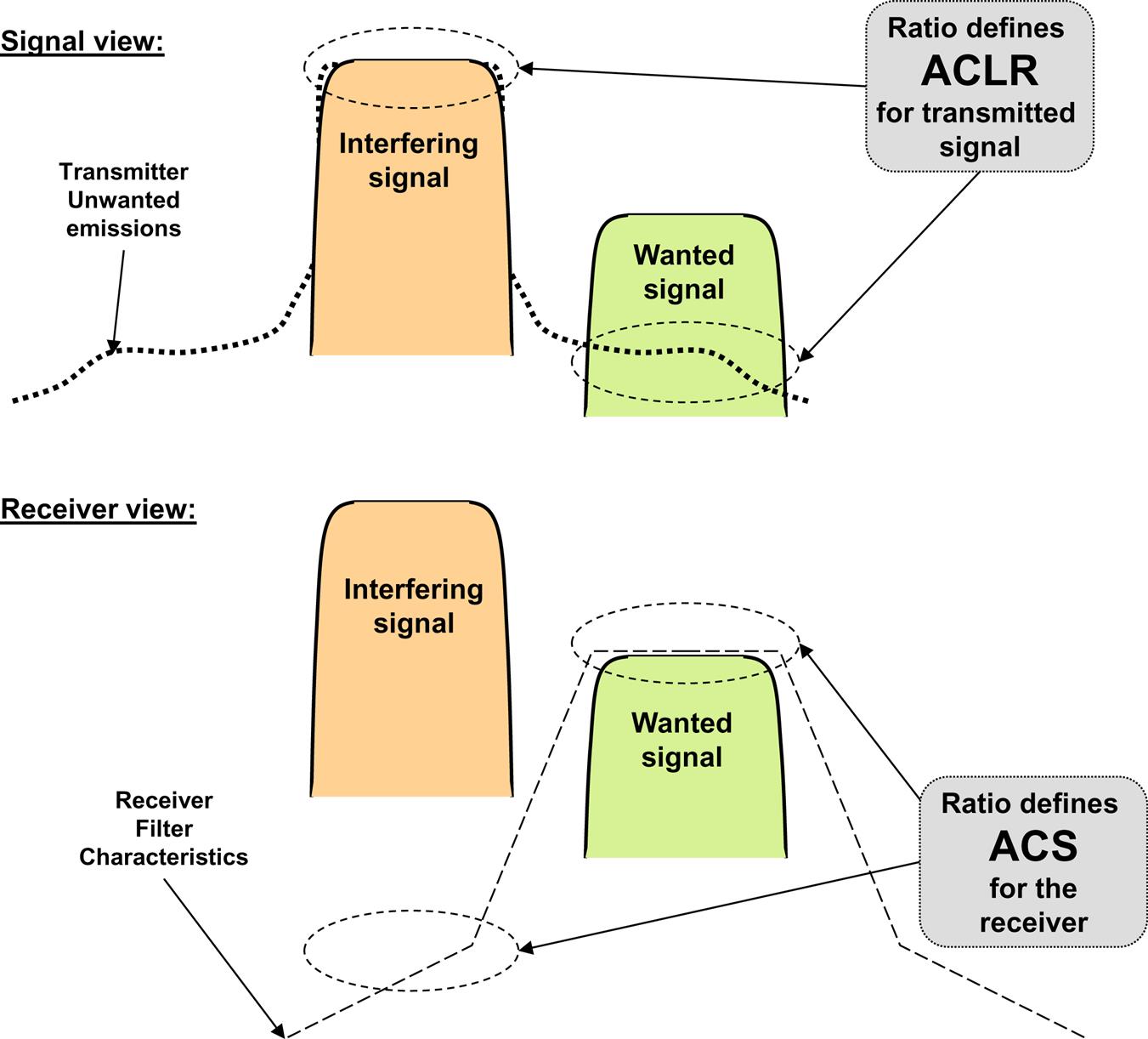
In addition to a spectrum emissions mask, the OOB emissions are defined by an ACLR requirement. The ACLR concept is very useful for analysis of coexistence between two systems that operate on adjacent frequencies. The ACLR defines the ratio of the power transmitted within the assigned channel bandwidth to the power of the unwanted emissions transmitted on an adjacent channel. There is a corresponding receiver requirement called ACS, which defines a receiver’s ability to suppress a signal on an adjacent channel.
The definitions of ACLR and ACS are illustrated in Fig. 18.6 for a wanted and an interfering signal received in adjacent channels. The interfering signal’s leakage of unwanted emissions at the wanted signal receiver is given by the ACLR and the ability of the receiver of the wanted signal to suppress the interfering signal in the adjacent channel is defined by the ACS. The two parameters when combined define the total leakage between two transmissions on adjacent channels. That ratio is called the adjacent channel interference ratio (ACIR) and is defined as the ratio of the power transmitted on one channel to the total interference received by a receiver on the adjacent channel, due to both transmitter (ACLR) and receiver (ACS) imperfections.
This relation between the adjacent channel parameters is [11]:
(18.2)
ACLR and ACS can be defined with different channel bandwidths for the two adjacent channels, which is the case for some requirements set for NR due to the bandwidth flexibility. Eq. (18.2) will also apply for different channel bandwidths, but only if the same two channel bandwidths are used for defining all three parameters, ACIR, ACLR, and ACS, used in the equation.
The ACLR limits for NR device and base station are derived based on extensive analysis [11] of NR coexistence with NR or other systems on adjacent carriers.
For an NR base station, there are ACLR requirements both for an adjacent channel with an NR receiver of the same channel bandwidth and for an adjacent LTE receiver. The ACLR requirement for NR BS is set to 45 dB. This is considerably more strict than the ACS requirement for the device, which according to Eq. (18.2) implies that in the downlink, the device receiver performance will be the limiting factor for ACIR and consequently for coexistence between base stations and devices. From a system point of view, this choice is cost-efficient since it moves implementation complexity to the BS, instead of requiring all devices to have high-performance RF.
In the case of carrier aggregation for a base station, the ACLR (as other RF requirements) apply as for any multicarrier transmission, where the ACLR requirement will be defined for the carriers on the edges of the RF bandwidth. In the case of non-contiguous carrier aggregation where the sub-block gap is so small that the ACLR requirements at the edges of the gap will “overlap,” a special cumulative ACLR requirement (CACLR) is defined for the gap. For CACLR, contributions from carriers on both sides of the sub-block gap are accounted for in the CACLR limit. The CACLR limit is the same as the ACLR for the base station at 45 dB.
ACLR limits for the device are set both with assumed NR and an assumed UTRA receiver on the adjacent channel. In the case of carrier aggregation, the device ACLR requirement applies to the aggregated channel bandwidth instead of per carrier. The ACLR limit for NR devices is set to 30 dB. This is considerably relaxed compared to the ACS requirement for the BS, which according to Eq. (18.2) implies that in the uplink, the device transmitter performance will be the limiting factor for ACIR and consequently for coexistence between base stations and devices.
18.9.4 Spurious Emissions
The limits for base station spurious emissions are taken from international recommendations [42], but are only defined in the region outside the frequency range of operating band unwanted emission limits as illustrated in Fig. 18.4—that is, at frequencies that are separated from the base-station transmitter operating band by at least 10–40 MHz. There are also additional regional or optional limits for protection of other systems that NR may coexist with or even be co-located with. Examples of other systems considered in those additional spurious emissions requirements are GSM, UTRA FDD/TDD, CDMA2000, and PHS.
Device spurious emission limits are defined for all frequency ranges outside the frequency range covered by the SEM. The limits are generally based on international regulations [42] but there are also additional requirements for coexistence with other bands when the device is roaming. The additional spurious emission limits can have an associated network signaling value.
In addition, there are base-station and device emission limits defined for the receiver. Since receiver emissions are dominated by the transmitted signal, the receiver spurious emission limits are only applicable when the transmitter is not active, and also when the transmitter is active for an NR FDD base station that has a separate receiver antenna connector.
18.9.5 Occupied Bandwidth
Occupied bandwidth is a regulatory requirement that is specified for equipment in some regions, such as Japan and the USA. It was originally defined by the ITU-R as a maximum bandwidth, outside of which emissions do not exceed a certain percentage of the total emissions. The occupied bandwidth is for NR equal to the channel bandwidth, outside of which a maximum of 1% of the emissions are allowed (0.5% on each side).
18.9.6 Transmitter Intermodulation
An additional implementation aspect of an RF transmitter is the possibility of intermodulation between the transmitted signal and another strong signal transmitted in the proximity of the base station or device. For this reason, there is a requirement for transmitter intermodulation.
For the base station, the requirement is based on a stationary scenario with a co-located other base-station transmitter, with its transmitted signal appearing at the antenna connector of the base station being specified but attenuated by 30 dB. Since it is a stationary scenario, there are no additional unwanted emissions allowed, implying that all unwanted emission limits also have to be met with the interferer present.
For the device, there is a similar requirement based on a scenario with another device-transmitted signal appearing at the antenna connector of the device being specified but attenuated by 40 dB. The requirement specifies the minimum attenuation of the resulting intermodulation product below the transmitted signal.
18.10 Conducted Sensitivity and Dynamic Range
The primary purpose of the reference sensitivity requirement is to verify the receiver noise figure, which is a measure of how much the receiver’s RF signal chain degrades the SNR of the received signal. For this reason, a low-SNR transmission scheme using QPSK is chosen as a reference channel for the reference sensitivity test. The reference sensitivity is defined at a receiver input level where the throughput is 95% of the maximum throughput for the reference channel.
For the device, reference sensitivity is defined for the full channel bandwidth signals and with all resource blocks allocated for the wanted signal.
The intention of the dynamic range requirement is to ensure that the receiver can also operate at received signal levels considerably higher than the reference sensitivity. The scenario assumed for base-station dynamic range is the presence of increased interference and corresponding higher wanted signal levels, thereby testing the effects of different receiver impairments. In order to stress the receiver, a higher SNR transmission scheme using 16QAM is applied for the test. In order to further stress the receiver to higher signal levels, an interfering AWGN signal at a level 20 dB above the assumed noise floor is added to the received signal. The dynamic range requirement for the device is specified as a maximum signal level at which the throughput requirement is met.
18.11 Receiver Susceptibility to Interfering Signals
There is a set of requirements for base station and device, defining the receiver’s ability to receive a wanted signal in the presence of a stronger interfering signal. The reason for the multiple requirements is that, depending on the frequency offset of the interferer from the wanted signal, the interference scenario may look very different and different types of receiver impairments will affect the performance. The intention of the different combinations of interfering signals is to model as far as possible the range of possible scenarios with interfering signals of different bandwidths that may be encountered inside and outside the base-station and device receiver operating band.
While the types of requirements are very similar between base station and device, the signal levels are different, since the interference scenarios for the base station and device are very different. There is also no device requirement corresponding to the base-station ICS requirement.
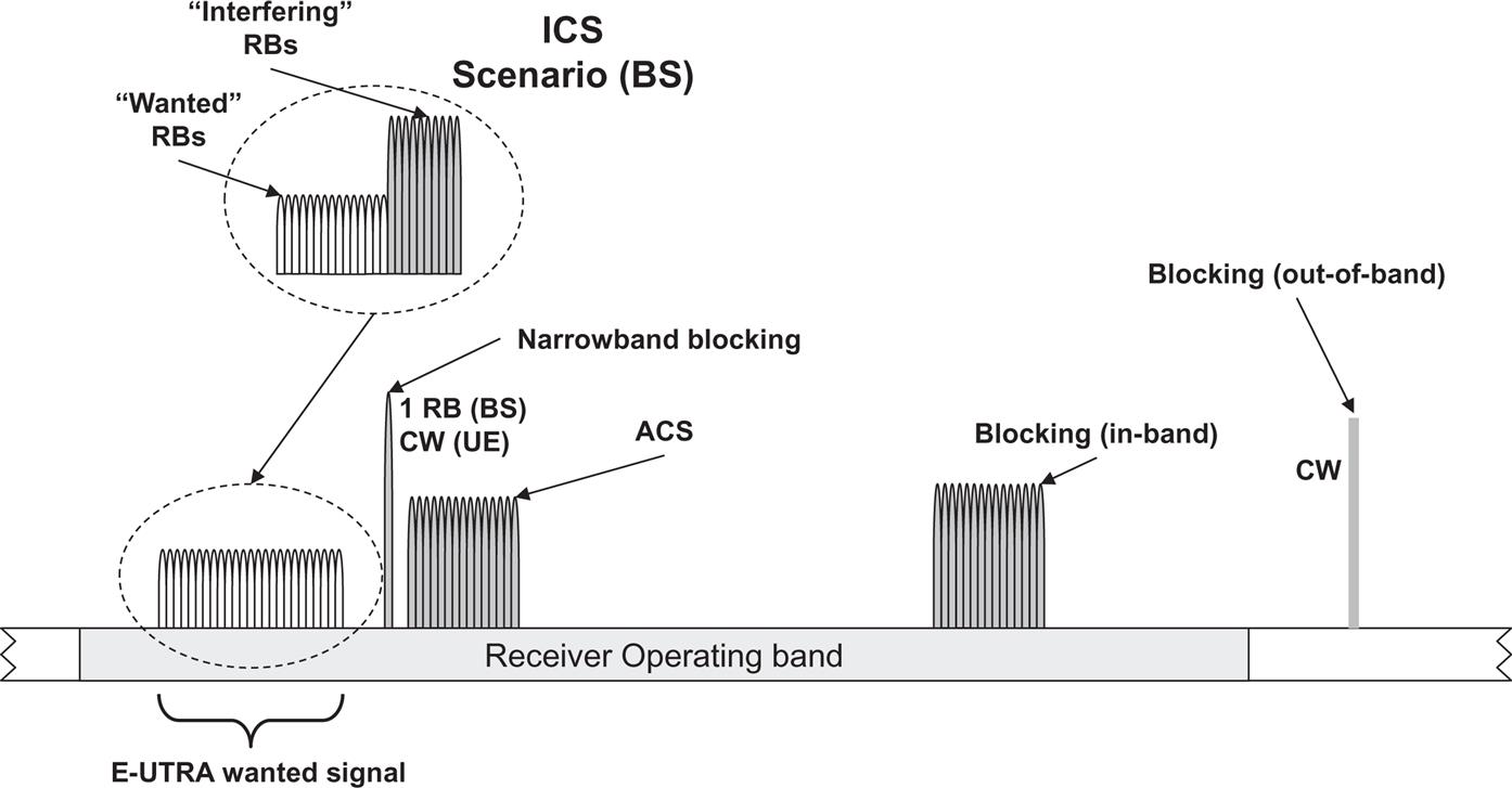
The following requirements are defined for NR base station and device, starting from interferers with large frequency separation and going close in (see also Fig. 18.7). In all cases where the interfering signal is an NR signal, it has the same or smaller bandwidth than the wanted signal, but at most 20 MHz.
- • Blocking: This corresponds to the scenario with strong interfering signals received outside the operating band (out-of-band blocking) or inside the operating band (in-band blocking), but not adjacent to the wanted signal. In-band blocking includes interferers in the first 20–60 MHz outside the operating band for the base station and the first 15 MHz for the device. The scenarios are modeled with a continuous wave (CW) signal for the out-of-band case and an NR signal for the in-band case. There are additional (optional) base-station blocking requirements for the scenario when the base station is co-located with another base station in a different operating band. For the device, a fixed number of exceptions are allowed from the out-of-band blocking requirement, for each assigned frequency channel and at the respective spurious response frequencies. At those frequencies, the device must comply with the more relaxed spurious response requirement.
- • Adjacent channel selectivity: The ACS scenario is a strong signal in the channel adjacent to the wanted signal and is closely related to the corresponding ACLR requirement (see also the discussion in Section 18.9.3). The adjacent interferer is an NR signal. For the device, the ACS is specified for two cases with a lower and a higher signal level.
- • Narrowband blocking: The scenario is an adjacent strong narrowband interferer, which in the requirement is modeled as a single resource block NR signal for the base station and a CW signal for the device.
- • In-channel selectivity (ICS): The scenario is multiple received signals of different received power levels inside the channel bandwidth, where the performance of the weaker “wanted” signal is verified in the presence of the stronger “interfering” signal. ICS is only specified for the base station.
- • Receiver intermodulation: The scenario is two interfering signals near to the wanted signal, where the interferers are one CW and one NR signal (not shown in Fig. 18.7). The purpose of the requirement is to test receiver linearity. The interferers are placed in frequency in such a way that the main intermodulation product falls inside the wanted signal’s channel bandwidth. There is also a narrowband intermodulation requirement for the base station where the CW signal is very close to the wanted signal and the NR interferer is a single RB signal.
For all requirements except ICS, the wanted signal uses the same reference channel as in the corresponding reference sensitivity requirement. With the interference added, the same 95% relative throughput is met as for the reference sensitivity, but at a “desensitized” higher wanted signal level.
18.12 Radiated RF Requirements for NR
Many of the radiated RF requirements defined for devices and base stations are derived directly from the corresponding conducted RF requirements. Unlike conducted requirements, the radiated requirements will account also for the antenna. When defining emission levels such as base station output power and unwanted emissions, this can be done either by incorporating the antenna gain as a directional requirement using an effective isotropic radiated power (EIRP) or by definition of limits using total radiated power (TRP). Two new radiated requirements are defined as directional for the base station (see Section 18.12.2), but most radiated device and base station requirements for NR are defined with limits expressed as TRP. There are several reasons for this choice [19].
TRP and EIRP are directly related through the number of radiating antennas and depend also on specific base station implementation, considering the geometry of the antenna array and the correlation between unwanted emission signals from different antenna ports. The implication is that an EIRP limit could result in different levels of total radiated unwanted emission power depending on the implementation. An EIRP limit will thus not give control of the total amount of interference in the network, while a TRP requirement limits the total amount of interference injected in the network regardless of the specific BS implementation.
Another relevant element behind the 3GPP choice of defining unwanted emission as TRP is the different behavior between passive and AAS. In the case of passive systems, the antenna gain does not vary much between the wanted signal and unwanted emissions. Thus, EIRP is directly proportional to TRP and can be used as a substitute. For an active system such as NR, the EIRP could vary greatly between the wanted signal and unwanted emissions and also between implementations, so EIRP is not proportional to TRP and using EIRP to substitute TRP would be incorrect.
The radiated RF requirements for device and base station are described below.
18.12.1 Radiated Device Requirements in FR2
As described in Section 18.4, the RF requirements in FR2 operating bands are described in a separate specification [6] for devices, because of the higher number of antenna elements for operation in FR2 and the high level of integration expected when using mm-wave technology. The set of requirements is basically the same as the conducted RF requirements defined for FR1 operating bands. The limits for many requirements are however different. The difference in coexistence at mm-wave frequencies leads to lower requirements on, for example, ACLR and spectrum mask. This is demonstrated through co-existence studies performed in 3GPP and documented in [11]. The possibility for different limits has also been demonstrated in academia [73].
The implementation using mm-wave technologies is more challenging than using the more mature technologies in the frequency bands below 6 GHz (FR1). The mm-wave RF implementation aspects are further discussed in Chapter 19.
It should also be noted that the channel bandwidths and numerologies defined for FR2 are in general different from FR1, making it not possible to compare requirement levels, especially for receiver requirements.
The following is a brief overview of the radiated RF requirements in FR2:
- • Output power level requirements: Maximum output power is of the same order as in FR1 but is expressed both as TRP and EIRP. The minimum output power and transmitter OFF power levels are higher than in FR1. Radiated transmit power is an additional radiated requirement, which unlike the maximum output power is directional.
- • Transmitted signal quality: Frequency error and EVM requirements are defined similar to what is done in FR1 and mostly with the same limits.
- • Radiated unwanted emissions requirements: Occupied bandwidth, ACLR, spectrum mask, and spurious emissions are defined in the same way as for FR1. The latter two are based on TRP. Many limits are less strict than in FR1. ACLR is on the order of 10 dB relaxed compared to FR1, due to more favorable coexistence.
- • Reference sensitivity and dynamic range: Defined in the same way as in FR1, but levels are not comparable.
- • Receiver susceptibility to interfering signals: ACS, in-band and out-of-band blocking are defined as for FR1, but there is no narrow-band blocking scenario defined since there are only wideband systems in FR2. ACS is on the order of 10 dB relaxed compared to FR1, due to more favorable coexistence.
18.12.2 Radiated Base-Station Requirements in FR1
As described in Section 18.5, the RF requirements for BS type 1-O consisted of only radiated (OTA) requirements. These are in general based on the corresponding conducted requirements, either directly or through scaling. Two additional radiated requirements defined are radiated transmit power and OTA sensitivity, described further below.
BS type 1-H is defined with a “hybrid” set of requirements consisting mostly of conducted requirements and in addition two radiated requirements, which are the same as for BS type 1-O:
- • Radiated transmit power is defined accounting for the antenna array beam-forming pattern in a specific direction as EIRP for each beam that the base station is declared to transmit. In a way similar to BS output power, the actual requirement is on the accuracy of the declared EIRP level.
- • OTA sensitivity is a directional requirement based on a quite elaborate declaration by the manufacturer of one or more OTA sensitivity direction declarations (OSDDs). The sensitivity is in this way defined accounting for the antenna array beam-forming pattern in a specific direction as declared equivalent isotropic sensitivity (EIS) level towards a receiver target. The EIS limit is to be met not only in a single direction but within a range of angle of arrival (RoAoA) in the direction of the receiver target. Depending on the level of adaptivity for the AAS BS, two alternative declarations are made:
- • If the receiver is adaptive to direction, so that the receiver target can be redirected, the declaration contains a receiver target redirection range in a specified receiver target direction. The EIS limit should be met within the redirection range, which is tested at five declared sensitivity RoAoA within that range.
- • If the receiver is not adaptive to direction and thus cannot redirect the receiver target, the declaration consists of a single sensitivity RoAoA in a specified receiver target direction, in which the EIS limit should be met.
Note that the OTA sensitivity is defined in addition to the reference sensitivity requirement, which exists both as conducted (for BS type 1-H) and radiated (for BS type 1-O).
18.12.3 Radiated Base-Station Requirements in FR2
As described in Section 18.5, the RF requirements for BS type 2-O are radiated requirements for base stations in FR2 operating bands. These are described separately, together with the radiated requirements for BS type 1-O, but in the same specification [4] as the conducted base-station RF requirements.
The set of requirements is identical to the radiated RF requirements defined for FR1 operating bands described above, but the limits for many requirements are different. As for the device, the difference in coexistence at mm-wave frequencies leads to lower requirements on, for example, ACLR, ACS as demonstrated through 3GPP coexistence studies [11]. The implementation using mm-wave technologies is also more challenging than using the more mature technologies in the frequency bands below 6 GHz (FR1) as further discussed in Chapter 19.
The following is a brief overview of the radiated RF requirements in FR2:
- • Output power level requirements: Maximum output power is the same for FR1 and FR2, but is scaled from the conducted requirement and expressed as TRP. There is in addition a directional radiated transmit power requirement. The dynamic range requirement is defined similarly to FR1.
- • Transmitted signal quality: Frequency error, EVM, and time-alignment requirements are defined similar to what is done in FR1 and mostly with the same limits.
- • Radiated unwanted emissions requirements: Occupied bandwidth, spectrum mask, ACLR, and spurious emissions are defined in the same way as for FR1. The three latter are based on TRP and also have less strict limits than in FR1. ACLR is on the order of 15 dB, relaxed compared to FR1, due to more favorable coexistence.
- • Reference sensitivity and dynamic range: Defined in the same way as in FR1, but levels are not comparable. There is in addition a directional OTA sensitivity requirement.
- • Receiver susceptibility to interfering signals: ACS, in-band, and out-of-band blocking are defined as for FR1, but there is no narrow-band blocking scenario defined since there are only wideband systems in FR2. ACS is relaxed compared to FR1, due to more favorable coexistence.
18.13 Ongoing Developments of RF Requirements for NR
The first set of NR specifications in 3GPP release 15 does not have full support for some RF deployment options that exist for LTE. Multistandard radio (MSR) base stations, multiband base stations, and non-contiguous operation are features that are under development in 3GPP and will have full support in the final release 15 specifications, or in some cases in release 16. A short description of those features is given below, where a more detailed description (applicable to LTE) can be found in Ref. [28].
18.13.1 Multistandard Radio Base Stations
Traditionally the RF specifications have been developed separately for the different 3GPP radio-access technologies GSM/EDGE, UTRA, LTE, and NR. The rapid evolution of mobile radio and the need to deploy new technologies alongside the legacy deployments has, however, led to implementation of different radio-access technologies (RAT) at the same sites, sharing antennas and other parts of the installation. In addition, operation of multiple RATs is often done within the same base-station equipment. The evolution to multi-RAT base stations is fostered by the evolution of technology. While multiple RATs have traditionally shared parts of the site installation, such as antennas, feeders, backhaul, or power, the advance of both digital baseband and RF technologies enables a much tighter integration.
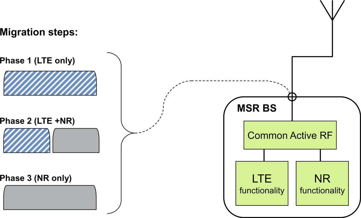
3GPP defines an MSR base station, as a base station where the receiver and the transmitter are capable of simultaneously processing multiple carriers of different RATs in common active RF components. The reason for this stricter definition is that the true potential of multi-RAT base stations, and the challenge in terms of implementation complexity, comes from having a common RF. This principle is illustrated in Fig. 18.8 with an example base station capable of both NR and LTE. Some of the NR and LTE baseband functionality may be separate in the base station but is possibly implemented in the same hardware. The RF must, however, be implemented in the same active components as shown in the figure.
While development of MSR BS specifications including NR is part of the work in 3GPP release 15, the set of specifications first issued for NSA operation will in the first step not cover the MSR BS specifications. It is expected that NR will be added as a new RAT for MSR BS during 2018. The main advantages of an MSR base station implementation for NR are twofold:
- • Migration between RATs in a deployment, for example, from previous mobile generations to NR, is possible using the same base-station hardware. The operation of NR can then be introduced gradually over time when parts of the spectrum used for previous generations is freed up for NR.
- • A single base station designed as an MSR base station can be deployed in various environments for single-RAT operation for each RAT supported, as well as for multi-RAT operation, where that is required by the deployment scenario. This is also in line with the recent technology trends seen in the market, with fewer and more generic base-station designs. Having fewer varieties of base station is an advantage both for the base-station vendor and for the operator, since a single solution can be developed and implemented for a variety of scenarios.
The MSR concept has a substantial impact for many requirements, while others remain completely unchanged. A fundamental concept introduced for MSR base stations is RF bandwidth, which is defined as the total bandwidth over the set of carriers transmitted and received. Many receiver and transmitter requirements are usually specified relative to the carrier center or the channel edges. For an MSR base station, they are instead specified relative to the RF bandwidth edges, in a way similar to carrier aggregation. By introducing the RF bandwidth concept and introducing generic limits, the requirements for MSR shift from being carrier centric towards being frequency block centric, thereby embracing technology neutrality by being independent of the access technology or operational mode.
For the specification of MSR base stations, the operating bands are divided into band categories (BC) depending on what RATs are supported in the band. There are presently three band categories, BC1–BC3, covering paired bands without GSM operation, paired bands with GSM operation and unpaired bands, respectively. It is not yet determined whether new band categories could be needed when NR is added as additional RAT.
Another important concept for MSR base stations is the supported capability set (CS), which is part of the declaration of base-station capabilities by the vendor. The capability set defines all supported single RATs and multi-RAT combinations. There are currently 15 capability sets, CS1–CS15, defined in the MSR BS test specification [2]. When NR is added as a new RAT, it is expected that the new CS will be added to cover RAT combinations that include NR operation.
Carrier aggregation is also applicable to MSR base stations. Since the MSR specification has most of the concepts and definitions in place for defining multicarrier RF requirements, whether aggregated or not, the differences for the MSR requirements compared to non-aggregated carriers are very minor.
More details on the RF requirements for MSR base stations supporting LTE, UTRA, and GSM/EDGE operation are given in Section 22.5 of Ref. [28].
18.13.2 Multiband-Capable Base Stations
The 3GPP specifications have been continuously developed to support larger RF bandwidths for transmission and reception through multicarrier and multi-RAT operation and carrier aggregation within a band and with requirements defined for one band at a time. This has been made possible with the evolution of RF technology supporting larger bandwidths for both transmitters and receivers. From 3GPP release 11, there is support in the LTE and MSR base-station specifications for simultaneous transmission and/or reception in two bands through a common radio. Such a multiband base station covers multiple bands over a frequency range of a few 100 MHz. Support for more than two bands is given from 3GPP release 14.
While development of NR specifications for multiband base stations is not excluded from the work in 3GPP release 15, the set of specifications first issued for NSA operation does not have full descriptions of multiband operation of NR for bands in frequency range 2.
One obvious application for multiband base stations is for interband carrier aggregation. It should however be noted that base stations supporting multiple bands were in existence long before carrier aggregation was introduced in LTE and UTRA. Already for GSM, dual-band base stations were designed to enable more compact deployments of equipment at base-station sites, but they were really two separate sets of transmitters and receivers for the bands that were integrated in the same equipment cabinet. The difference for “true” multiband-capable base stations is that the signals for the bands are transmitted and received in common active RF in the base station.
An example base station is illustrated in Fig. 18.9, which shows a base station with a common RF implementation of both transmitter and receiver for two operating bands X and Y. Through a duplex filter, the transmitter and receiver are connected to a common antenna connector and a common antenna. The example is also a multi-RAT-capable MB-MSR base station, with LTE+GSM configured in band X and LTE configured in band Y. Note that the figure has only one diagram showing the frequency range for the two bands, which could either be the receiver or transmitter frequencies.
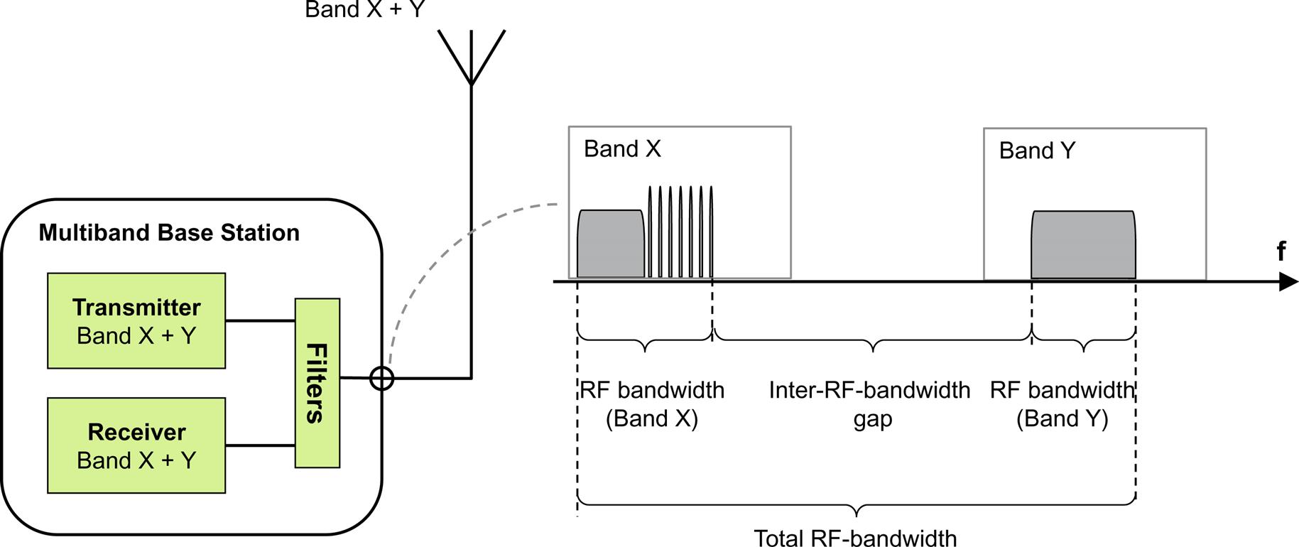
While having only a single antenna connector and a common feeder that connects to a common antenna is desirable to reduce the amount of equipment needed in a site, it is not always possible. It may also be desirable to have separate antenna connectors, feeders, and antennas for each band. An example of a multiband base station with separate connectors for two operating bands X and Y is shown in Fig. 18.10. Note that while the antenna connectors are separate for the two bands, the RF implementation for transmitter and receiver is in this case common for the bands. The RF for the two bands is separated into individual paths for band X and band Y before the antenna connectors through a filter. As for multiband base stations with a common antenna connector for the bands, it is also here possible to have either the transmitter or receiver be a single-band implementation, while the other is multiband.

Further possibilities are base station implementations with separate antenna connectors for receiver and transmitter, in order to give better isolation between the receiver and transmitter paths. This may be desirable for a multiband base station, considering the large total RF bandwidths, which will in fact also overlap between receiver and transmitter.
For a multiband base station, with a possible capability to operate with multiple RATs and several alternative implementations with common or separate antenna connectors for the bands and/or for the transmitter and receiver, the declaration of the base station capability becomes quite complex. What requirements will apply to such a base station and how they are tested will also depend on these declared capabilities.
More details on the RF requirements for multiband base stations supporting LTE operation is given in Section 22.12 of [28].
18.13.3 Operation in Non-contiguous Spectrum
Some spectrum allocations consist of fragmented parts of spectrum for different reasons. The spectrum may be a recycled 2G spectrum, where the original licensed spectrum was “interleaved” between operators. This was quite common for original GSM deployments, for implementation reasons (the original combiner filters used were not easily tuned when spectrum allocations were expanded). In some regions, operators have also purchased spectrum licenses on auctions and have for different reasons ended up with multiple allocations in the same band that are not adjacent.
For deployment of non-contiguous spectrum allocations there are a few implications:
- • If the full spectrum allocation in a band is to be operated with a single base station, the base station has to be capable of operation in non-contiguous spectrum.
- • If a larger transmission bandwidth is to be used than what is available in each of the spectrum fragments, both the device and the base station have to be capable of intraband non-contiguous carrier aggregation in that band.
Note that the capability for the base station to operate in non-contiguous spectrum is not directly coupled to carrier aggregation as such. From an RF point of view, what will be required by the base stations is to receive and transmit carriers over an RF bandwidth that is split in two (or more) separate sub-blocks, with a sub-block gap in-between, as shown in Fig. 18.11. The spectrum in the sub-block gap can be deployed by any other operator, which means that the RF requirements for the base station in the sub-block gap will be based on coexistence for uncoordinated operation. This has a few implications for some of the base station RF requirements within an operating band.
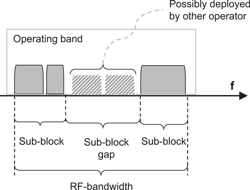
While development of NR BS specifications for non-contiguous spectrum is not excluded from the work in 3GPP Release 15, the set of specifications first issued for NSA operation does not have a full description of non-contiguous operation. More details on the RF requirements for non-contiguous operation for LTE are given in Section 22.4 of Ref. [28].