Chapter 22
Experiments in Live Capture and Transmission of Stereoscopic 3D Video Images
22.1. Introduction
From 2009 to 2011, the INTELSIG Laboratory of the University of Liège (ULg)1 produced 12 live “retransmissions” in stereoscopic 3D (S-3D). For each of them, INTELSIG acted as organizer and technical coordinator for the whole retransmission chain (capture, transmission, and visualization). These retransmissions were carried out for purely experimental, illustrative, and educational purposes, with the aim of pushing the boundaries of the state of the art. Each experiment involved a large number of partners, bringing to bear their expertise and technical means.
The idea behind the experiments initially arose in the course of the first 3D Stereo MEDIA (3DSM) event, in 2009. This international event was the brainchild of one of the authors of this chapter (Jacques G. Verly). It is devoted to all aspects and all applications of all forms of 3D. It aims to provide a meeting point for the scientific, technological, artistic, and business aspects of 3D.
These 12 retransmissions included four shows of varying types (2009), two surgical operations (2010), three steadicam interviews (2010), a transatlantic video presentation (2010), and two bicycle races (2011).
22.2. Retransmissions of various shows
Our first experiments with live S-3D retransmissions were carried out in the course of the first 3DSM event, which took place in the Palais des Congrès of Liège in Belgium, in 2009.
22.2.1. Capture
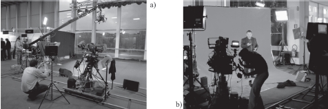
For each of the four retransmissions, the capture took place in a part of the hall used as an exhibition space (see Figure 22.1(a)), just outside of the conference rooms (where the S-3D images were projected). The first three experiments consisted in the retransmission of three different shows, each on a different day. The fourth – the highlight of the closing session – consisted of capturing a real person on a green key background (see Figure 22.1(b)), integrating him into a virtual set, and simultaneously introducing a virtual character conversing with the real person, all – of course – in live S-3D. The virtual set, the virtual person, its animation, and the insertion were produced by NeuroTV.
Figure 22.1. Capture of a show in live S-3D in a hall of the Palais des Congrès of Liège. a) The artists evolved on a special surface laid onto the carpeting. To the left, one sees exhibition stands. b) The green key used to insert a real person into a virtual set. The wooden floor and the tracks show the relation to the previous image
22.2.2. Transmission
The high-definition (HD) images from the various S-3D rigs were transmitted at full resolution along coaxial cables (HD-SDI signals) to an outside broadcast (OB) van from Outside Broadcast located outside the Palais des Congrès. In the van, the S-3D images were examined, adjusted, and mixed into two synchronized signals, which were then sent down via two optical fiber cables to the projection booth of the 500-seat conference room, where the optical signals were reconverted into HD-SDI signals sent to the S-3D projector.
22.2.3. Visualization
For each edition of 3DSM, we have to choose, obtain, install, and select the various S-3D projectors that we need. Most projectors intended for cinemas are designed to project films using contents called digital cinema packages (DCPs). Any other use of these projectors requires specific technical knowledge; and this is the case for live retransmissions.
During the various editions of 3DSM held at the Palais des Congrès of Liège, we used two BARCO projectors of type DP2000 or equivalent. After conversion, the left and right images were brought into the projector via its HD-SDI inputs. Figure 22.4(b) shows an example of a DP2000 projector of the type we used.
22.3. Retransmissions of surgical operations
Our retransmissions of surgical operations [AUD 10, VER 10d, VER 11] took place in 2010 as part of the ninth edition of the ImagéSanté Festival, organized once every two years by the ULg under the direction of Dr. Philippe Kolh, a professor at the ULg and a heart surgeon at the University Hospital of Liège. This hospital is known as the “Centre hospitalier universitaire” (CHU) of Liège. The festival is popular among students in medicine and in other associated domains, professionals in the same sectors, and the general public. The live retransmissions of surgical operations are particularly popular.
The INTELSIG Laboratory had already participated in the festival in 2008, with the addition of a scientific conference called “Medical Imaging”. Jacques G. Verly had then proposed to launch another event, independent from ImagéSanté, on all aspects of “3D”. This event was called 3D Stereo MEDIA (3DSM), and its first edition took place in 2009. Given that 3DSM had been launched shortly after the Medical Imaging conference, Philippe Kolh wished to examine the possibility of a live S-3D retransmission of a surgical operation as part of the ImagéSanté Festival of 2010.
The aim of the retransmission was to film in S-3D a surgical operation in one of the operating rooms of the CHU of Liège (on the Sart-Tilman site, in the suburbs of Liège), transmit the live images to the Cinéma Sauvenière in the center of Liège (almost 12 km away as the crow flies), and to project the S-3D images in a 300-seat movie theater. A bidirectional vocal link was also required, allowing the surgeon to comment on the operation, the audience to ask questions, and the surgeon to provide answers. It should be noted that, at the time, the cinema was not equipped with a S-3D projector. We thus had a lot of things to do. . .
We envisioned various types of surgical operations. In the end, we selected a non-endoscopic operation and, specifically, a neurosurgical operation. One reason for this choice was the collaboration between Dr. Didier Martin, a professor at the ULg and a neurosurgeon at the CHU, and Jacques G. Verly in the domain of image-assisted neurosurgical navigation. Another reason is that the zone concerned by the operation was relatively limited, which would allow us to optimize the S-3D capture and the depth budgets.
In addition to the operation planned for live transmission, the decision was made to film another operation beforehand in order to identify potential problems, optimize S-3D capture, and provide a backup recording in case of problems with the live retransmission.
The first surgical operation took place on 25 February 2010. It consisted of treating an aneurysm by installing a clip. It lasted about five hours. The operation was captured and recorded, but was not retransmitted. However, a variety of transmission tests were carried out between the CHU and our laboratories during the month of March, to check that we had correctly identified the access points at the hospital for the appropriate optical fibers, and that the desired data rate of 500 Mbits/s could be maintained over several hours without experiencing any contention. The tests showed that the data rate could reach almost 1 Gbits/s in a continuous manner.
The recordings were then used to create a montage, made up of a variety of clips; this represented a challenge in itself as few local companies had the necessary facilities for S-3D montage and S-3D visualization. The clips were also shown during the live surgery during periods judged to be of limited interest for the audience.
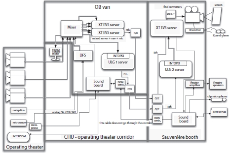
The second surgical operation took place on 18 March 2010. It was recorded and retransmitted live. A relatively short surgical procedure was selected to fit into the scheduled 2.5 h session in the cinema. The operation consisted of the extraction of a meninx tumor (meningioma). As a result of a bidirectional vocal link, the members of the audience were able to ask questions and the surgeon was able to answer them or to comment on the surgery. Figure 22.2 shows the architecture of the whole retransmission chain, including capture, transmission, and projection, which we describe below.
Figure 22.2. Block diagram of the full retransmission chain, including capture, transmission, and projection
22.3.1. Capture
The two operations took place in the operating room 16 at the CHU (see Figure 22.3(a)). As the operation was going to be projected onto a large screen of a 300-seat movie theater, the left and right images of each S-3D pair were both transmitted in lightly compressed full HD, meaning a total data rate of about 500 Mbits/s, which should be compared to the traditional data rates of 12–15 Mbits/s used for the festival.
The capture and stereography were carried out by Binocle, under the direction of Yves Pupulin. We decided to install three S-3D rigs (see Figure 22.3(b)): the static rig at the patient’s feet, the second next to the first and opposite to the surgeon, and the third mounted on a crane to film over the shoulder of the surgeon’s assistant. One challenge was to place all of the required equipment in the restricted space of an operating room, while allowing the personnel to easily move around the patient. Another challenge was to meet the sterilization requirements.
Figure 22.3. a) Plan of part of the operating room of interest at the CHU of Liège, with, at bottom right, the balcony and its wall that various cables were drawn over. b) Arrangement of the three S-3D rigs around the operating table. The capture operators wore standard operating room clothing

22.3.2. Transmission
To minimize the risks associated with transmission, we decided that we could not tolerate the slightest competition on our communication line, which notably excluded the use of Internet. The required data rate of 500 Mbits/s over the 2 h of the operation excluded the possibility of a satellite link due to bandwidth restrictions and the cost of renting a satellite channel for 2 h, alongside the near impossibility of advance testing. The only possible solution was to use dedicated optical fibers between the CHU and the cinema.
SOFICO indicated that they had fibers between the CHU and the city center, but not up to the cinema. Given the size of the CHU, it was difficult to find the point of entry/exit of the optical fibers. Once the point had been located, technical personnel from the CHU and the ULg installed a cable from this point to the technical room 17, close to the operating room 16 (see Figure 22.3(a)). On the cinema side, SOFICO opened up almost 300 m of sidewalk in the city center and installed the required optical fibers, which were then extended to the sixth floor of the cinema. The required electrical/optical converters were installed at both ends. For added security, the fibers, which were initially butted, were fused together to produce a monolithic “glass” medium between the converters, i.e. over a distance of almost 16 km. Furthermore, two separate communication “tubes” were laid over completely different geographical pathways in case of an accident occurring along one of them (e.g. caused by diggers, etc.). Each cable contained dozens of individual fibers, but only one was used.
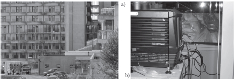
During the planning stage, we realized that a specially equipped OB van would be needed at the CHU for the manipulation and the mixing of the video streams from the three S-3D rigs. The van, provided by Notélé, was installed in the parking lot at the foot of the relevant building (see Figure 22.4(a)). Coaxial cables from the three rigs (HD-SDI signals) were run over the balcony wall outside of the operating room to the van (see Figures 22.3(a) and 22.4(a)). In the van, the S-3D images were corrected, adjusted, and mixed to create the image stream to be ultimately shown on the cinema screen. Before transmission, the images were compressed into JPEG 2000 in real time using a PRISTINE electronic board from INTOPIX. The sound was also integrated into the data stream. After electrical/optical conversion in the van, the final signal for transmission was sent to the technical room 17 (see Figure 22.3(a)), where the access point for the 16 km of fibers to the cinema was located. The routing of these cables between the operating room and the car, their protection against mechanical damage, and the sterility requirements presented major logistical challenges, not to mention the wild boars roaming on the CHU grounds!
Figure 22.4. a) OB van in the parking at the base of the building (far right) where the operating room was located (on the top floor). b) View from the projection booth at the Cinéma Sauvenière, showing the DP2000 projector that we had installed for the occasion and a partial view of an image projected onto the screen (showing the operating field), through the fireproof window of the booth
A backup plan was developed in case of problems with the transmission strategy: images, with a higher compression rate, were sent block by block over the Internet from an XT server from EVS located in the van to a similar server located in the cinema.
22.3.3. Visualization
As the Cinéma Sauvenière was not equipped with S-3D projection equipment at the time, we arranged for the temporary installation of a BARCO DP2000 projector, which we checked out intensively in the test center of the XDC company (now dcinex) in Liège.
In the projection booth, optical signals were converted into electrical signals, and then decompressed by a second PRISTINE board before being sent to the HD-SDI inputs of the BARCO projector (see Figure 22.4(b)). The projection booth also included a sound mixing table that gathered the ambient sounds from the video, the surgeon’s microphone signal transmitted using voice-over-IP (VOIP), and the cinema’s microphones, also transmitted to the operating room using VOIP.
When we selected the projector, we did not consider the losses caused by the passage of the light beam through the fireproof window of the projection booth (see Figure 22.4(b)). In spite of a significant loss of light, the S-3D images retained a sufficient level of brightness.
22.4. Retransmissions of “steadicam” interviews
For the retransmissions at 3DSM 2009, the capture and visualization locations were in close proximity. For 3DSM 2010, the decision was made to increase the distance between these locations. Visualization was maintained at the Palais des Congrès of Liège, but capture was moved to various sites in Liège [VER 10a, VER 10b]: the “Marché de Noël” (Christmas Market) on 8 December 2010 (see Figure 22.5(a), the “SOS Planet” exhibition at the Gare des Guillemins on 9 December, and the Pôle Image de Liège (PIL) on 10 December for its inauguration (see Figure 22.5(b)). In each case, the scenario consisted in an exploration of the location and in interviews of people. The exploration stage required the use of a steadicam; the transmission distance and the chosen locations led us to select a satellite link. A conventional 2D video camera was also used to allow the spectators watching the retransmission to see the S-3D steadicam in operation.
Figure 22.5. a) First steadicam capture location in Liège: the “Marché de Noël”. b) Third steadicam capture location in Liège: the Pôle Image de Liège (PIL) (courtesy of C. Iland from the PIL)

22.4.1. Capture
The left side of Figure 22.6 shows the architecture of the capture system. To be concrete, we will now describe the implementation of this architecture in the case of the “Marché de Noël”.
Figure 22.6. Architecture of capture and of part of transmission

The main sensor was a P+S Technik S-3D mirror rig mounted on a steadicam supplied by Transvideo. The images acquired by the rig were converted into a side-by-side (SbS) format by the rig and transmitted by radio from a transmitter on the rig to a fixed receiver, positioned in an optimal location. The images were directly converted to SbS as this was required before transmission to the satellite in any case. Figure 22.7(a) shows the steadicam on its base (with the rig, control screen, transmitter, etc.) and the reception/transmission system on the platform. The “candles” on the platform are radio antennas, providing spatial diversity to attenuate the multipath effect. The reception part receives images sent from the rig. The transmission part sends these images to the control monitor of the stereographer. Figure 22.7(b) shows a more detailed view of the reception/transmission system, supplied by Transvideo. The S-3D SbS images were then transmitted via a coaxial cable to a Radio-Tèlèvision Belge Francophone (RTBF) connection unit, which was out of sight, secured, and protected from weather conditions (it was snowing slightly) in one of the “chalets” of the village. From there, the S-3D images were sent via an optical fiber to the RTBF HD6 OB van. The 2D video camera was also linked to the above connection unit, and its images were sent to the OB van at the same time as the S-3D images. The purpose of this 2D camera was to allow spectators (at the Palais des Congrès) to watch the S-3D capture system at work. As this camera was linked to the connection unit via a cable, its field of action was limited, but satisfactory for our needs.
Figure 22.7. a) View of the steadicam on its base and of the fixed radio reception/transmission system (with “candle” antennas). b) Transvideo reception/transmission system. The system allowed one to receive images from the S-3D rig and to send them directly to the control unit of the stereographer. The system was also able to send images via coaxial cables, in this case to the RTBF connection unit

The stereographer (Erwan Davigano) had access to a control unit, allowing him to adjust the S-3D rig using a radio remote control, and to observe the obtained images on a Transvideo monitor; these images were transmitted by radio from the control unit to the Transvideo reception/transmission system. Unsurprisingly, the most delicate part of the capture system up to the optical fibers was the radio transmission of images. The frequency of 5 GHz essentially requires a direct line of sight between the transmission antenna and the reception antenna. We thus experimented to find the best position for the fixed radio system (the equipment with “candles”), that would allow us both to control the rig and to receive high quality S-3D images during the live retransmission. Sound was captured separately during retransmission, and inserted into the RTBF connection unit. Figures 22.8(a) and (b) show the capture system in operation. Note that, as a 2D camera was also used to film the S-3D rig in action, spectators could see images similar to the photos shown here.
22.4.2. Transmission
As we indicated earlier, we chose (somewhat arbitrarily) the optical fiber arriving at the transmission RTBF HD8 OB van as the transition point between the capture part and the transmission part (see Figure 22.9(a)). Similarly, we choose as the transition between the transmission part and the visualization part the optical fiber leaving the receive RTBF BEL69 satellite van (see Figure 22.9(b)) at the Palais des Congrès. The right side of Figure 22.6 shows the architecture of the uplink part of transmission, and the left side of Figure 22.10 shows the downlink part.
Figure 22.8. a) The S-3D steadicam in operation. The steadicammer is followed by the stereographer, who controls the rig by radio remote control. b) One of the exhibitors interviewed during the retransmission, who quickly realized that brandishing a sausage at the client was an excellent way of demonstrating the “jumping out of the sceen” effect

Upon entering the transmission OB van, the 2D and S-3D images were recorded for future analysis (before possible degradation during satellite transmission). For ease of mixing and projection, it was decided to convert 2D images into SbS, an unusual and somewhat paradoxical decision. An electronic system was even constructed at the last minute to carry out this conversion. The producer thus mixed the 2D and S-3D images during the transmission. The image stream sent to the satellite constituted the content that was shown.
Figure 22.9. a) RTBF HD8 OB van used to mix images and to send signals to the satellite (uplink). b) RTBF BEL69 satellite van used to receive signals from the satellite (downlink)
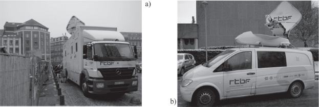
Figure 22.10. Architecture of part of the transmission system and of the visualization system
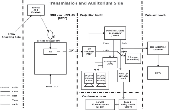
Eutelsat allowed us to use the Eutelsat AB1 satellite, located at 12.5° west. For each retransmission, Eutelsat allowed a period of 40 min of use, with 10 min for testing and 30 min for live retransmission. Several weeks before the retransmissions, Eutelsat also allowed satellite time for transmission testing from the RTBF site at Rhisnes. At the Palais des Congrès, the signals from the satellite were received by the RTBF BEL69 satellite van, and then sent over an optical fiber to the projection booth.
22.4.3. Visualization
The right side of Figure 22.10 shows the architecture of the visualization system. In the projection room of the 500-seat room, a Doremi Dimension-3Dcine converter separated the video and audio signals and converted the SbS (2D or 3D) video stream into two distinct synchronized streams, feeding the HD-SDI ports of a BARCO DP2000 projector. The interest of transforming 2D images into 2D SbS resides in the fact that it is then not necessary to activate/deactivate the side-by-side or double-stream functions of the projector with each change of camera.
22.5. Retransmission of a transatlantic video presentation
We invited Mark Schubin from Shubin Café, based in New York City (NYC), to deliver an invited presentation at 3DSM 2010. Due to professional obligations, he was unable to travel to Liège, but he offered to make his presentation via video conference from NYC. We then asked whether he was interested in making the presentation in S-3D, a challenge he was willing to take up with us.
The scenario that was ultimately retained is the following: there were two distinct sets of audiovisual content to project: a classic PowerPoint style presentation and a live S-3D video retransmission of Mark Schubin giving his presentation from NYC. The projection could therefore take different forms: the presentation alone, the presenter alone, or a combination of the two, for example showing the presentation at the base of the screen with a smaller window showing the presenter higher up. These various options were tested during live transmission, and the arrangement of the elements of the composite view was also adjusted live, as only 10 min of testing time was available immediately before the presentation. The solution that was ultimately chosen was to load the presentation onto a PC located in the projection booth and connected to the S-3D projector, and to let Mark Schubin take control of the presentation using the LogMeIn software.
22.5.1. Capture
S-3D capture was carried out by All-Mobile Video in NYC, using a 3ality S-3D rig. All stereographic adjustments were carried out in NYC, taking into account the screen size (9 m wide) and the dimensions of the room.
22.5.2. Transmission
Transmission was carried out using the same satellite used for the steadicam interviews, the Eutelsat AB1. It was this transmission which dictated the choice of satellite; as the satellite is within “view” of Liège, it was also suited for retransmissions with uplink and downlink points in Liège. In NYC, All-Mobile Video routed the signals to a satellite uplink point, probably using optical fibers. In Liège, the signals were captured by the RTBF BEL69 satellite van, already used for the retransmission of steadicam interviews. The images were then transmitted in SbS format, allowing them to be inserted into classic transmission schemes. One then talks about in-frame transmission.
There was, however, one major difference between the retransmissions from NYC and from Liège. In the case of the retransmissions between two points in Liège, which involved two RTBF vans, the choice of modulation to be used was easy and almost automatic. In the case of the transmission from NYC to Liège, the modulation used for the uplink was different to that generally used by the RTBF. This problem was rapidly identified during preliminary testing. Once the signals had been received and correctly demodulated, they were sent to the projection booth in exactly the same way used for the steadicam interviews.
22.5.3. Visualization
The visualization system was very similar to that used for the steadicam retransmissions. For a very short period at the beginning of the live session, we encountered color problems and an absence of depth. These problems were rapidly solved because of the perspicacity and reactiveness of the technical team. When Mark Schubin pressed a key on his computer in NYC, the audience in Liège saw the corresponding movement in the S-3D video, and the appropriate 2D slide appeared on screen.
22.6. Retransmissions of bicycle races
In early 2011, we provided technical assistance to the RTBF (French-speaking Belgian Radio and Television organization) for experimental live S-3D transmissions of two major bicycle races in Belgium [VER 10c]: the Flèche Wallonne (20 April 2011) and Liège-Bastogne-Liège (24 April 2011). In each case, tests were carried out the day before over part of the course and notably at the finish line.
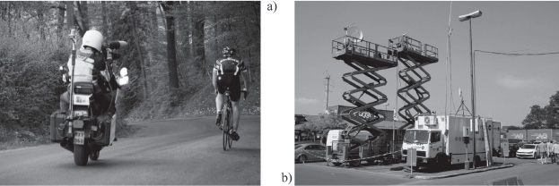
One constraint lay in the fact that these retransmissions could not disrupt the regular 2D retransmissions. Therefore, in addition to the four motorcycles used for standard 2D capture, the RTBF used a fifth motorcycle carrying specific S-3D capture equipment (see figure 22.11(a)). This motorcycle was also required to stay behind the racers. The chosen transmission channel corresponded to the backup channel for regular 2D transmission.
As the retransmissions were purely experimental, the images were visualized live in S-3D by the ULg and RTBF teams and a group of VIPs at the finish line, and they were not broadcast to the general public. They were also recorded for later analysis and for use in developing stereography algorithms. As far as we know, these live S-3D retransmissions over a whole race and using almost standard race infrastructure constituted a first.
22.6.1. Capture
As for classic 2D race retransmissions, the cameraman was positioned on the back of the S-3D capture motorcycle. Panasonic placed an AG-3DA1 camera at the disposal of the RTBF. The cameraman generally carried it on his shoulder. No image stabilization equipment (mechanical or electronic) was used. As the interaxial distance of the camera was fixed, the cameraman was only able to modify the convergence and the zoom. As none of the RTBF’s motorcycle cameraman had experience in S-3D capture, we provided basic stereography training to the chosen cameraman. In addition, we were in permanent radio contact with him: based on the images visualized at the finish line, we were able to give him precise real-time instructions for adjusting the camera controls, improving image quality, and testing a variety of shooting strategies, showing the advantages and disadvantages of each.
The “language” of S-3D filming for bicycle races remains to be defined, and it can only be developed and refined through field experimentation. With this in mind, we tested a variety of view capture methods: in the direction of movement of the motorcycle, toward the front (close-up and far); toward the back (close-up and far); while overtaking, or being overtaken by cyclists, using a panning to follow them; toward the back with the camera close to the ground (as sometimes seen in 2D retransmissions); and with both a stationary motorcycle and a fixed camera direction.
22.6.2. Transmission
To enable in-frame transmission over existing 2D channels, the RTBF added a Davio converter to the classic motorcycle transmission equipment. The converter was used to convert the left and right HD streams produced by the camera into a side-by-side (SbS) HD stream suited for transmission over standard radio channels. The raw images produced by the camera were also recorded on a pair of SD memory maps located in the camera itself. This allowed us to preserve the raw images, avoiding losses of resolution and degradations due to SbS conversion and to transmission. The addition of the Davio converter obliged us to rig up a specific electrical power supply (feeding the motorcycle battery). While the available current was sufficient in continuous conversion mode, it proved to be insufficient to read the memory maps used to program the Davio, something which compromised the transmission tests carried out the day before the first race.
The SbS images were then transmitted in the conventional way to the helicopter and airplane following the race and from these air vehicles to the OB van at the finish line. As the S-3D images were not broadcast to the general public, they were not subject to mixing and transmission over a longer distance, for example via an RTBF tower such as the one located at the Bol d’Air outside of Liège. The helicopter is generally used to “retrieve” images from deep valley areas.
22.6.3. Visualization
The images received by the airplane or helicopter were then transmitted to the radio antennas and receivers on the finish line (see Figure 22.11(b)). During testing at the Flèche Wallonne race, the images were examined on a S-3D monitor in the back of a vehicle. For the Liège-Bastogne-Liège race, the images were shown on a large Panasonic 3D-screen (with active glasses) in a tent close to the finish line, accessible to VIP visitors. The line and the tent were located close to the equipment shown in Figure 22.11(b).
Viewers of the S-3D retransmission of the Liège-Bastogne-Liège race on the large S-3D screen were unanimous in recognizing the interest of S-3D for the retransmission of bicycle races. Evidently, image stabilization would have been desirable in many cases.
Figure 22.11. a) View of the traditional radio transmission equipment on the back of the S-3D capture motorcycle. The side-by-side Davio converter is not visible. b) A variety of radio reception equipment on the finish line at Ans during the 2011 Liège-Bastogne-Liège race
A variety of interesting phenomena were observed during retransmission. One of the most striking examples involved the rear-view mirror of the motorcycle, which was in the field of vision of the camera: the scene observed in the mirror was also in S-3D! A video montage with highlights of each race was produced at the CRIG in Liège and was shown by the authors during a presentation at 3DSM in December 2011. The presentation was followed by a debate during which experienced stereographers were able to draw lessons from these pioneering, experimental retransmissions.
22.7. Conclusion
In this chapter, we have described the live stereoscopic (S-3D) transmissions in which we were involved from 2009 to 2011 as architects, technical advisers, and/or instigators. At the time when we began planning these retransmissions (in 2008), live S-3D retransmissions were a rarity and constituted highly visible technical exploits. Moreover, our work took place at the very beginning of 3D-TV and S-3D broadcast channels. Sky 3D (Korea) was the first 3D broadcast channel in continuous operation (1 January 2010). In Europe, the British company BSkyB began offering a limited service on 3 April 2010, with retransmission of a match to more than 1,000 bars and sporting clubs in England. Our retransmission of a surgical operation using full HD, rather than side-by-side technology, took place on 25 March 2010, just before this first BSkyB broadcast. All of our experiments may thus be considered to be pioneering.
Live S-3D retransmission involves all of the difficulties of S-3D, i.e. capture, transmission, and visualization, simultaneously. Each domain is a challenge in itself and presents a rich terrain for scientific and technical development. Moreover, while stereography for live action (as opposed to computer animation) is already difficult in the best possible capture conditions, such as on a film set, it must be carried out almost instantly in the case of live transmission, with no opportunity for later corrections. While significant progress has been made in computer-controlled stereography, there is currently no fully automatic solution to the problem, despite the claims made by some companies.
In our experiments, we have often pushed the boundaries of technical possibilities, whether by adding virtual and real characters into virtual surroundings, transmitting S-3D streams with each image in full HD (in contrast to traditional in-frame methods, such as those resulting from SbS conversion), or capturing mobile subjects (cyclists) from a mobile platform (motorcycle) with constantly changing backgrounds, for which we do not have detailed information in advance.
Because of the new challenges encountered, the retransmissions we performed were generally not feasible (at a reasonable cost) for traditional broadcasters, mostly because they operate in highly limited contexts, with a constant and justified focus on reliability. Because of the technical resources required, often not fully known beforehand, these retransmissions were not feasible for researchers and academics. Our retransmissions were therefore a particularly suitable subject for collaboration between research and broadcasting teams, groups that do not generally meet. In addition to technical questions, some “soft skills” were clearly needed to allow the teams to communicate effectively, and to collaborate and come up with solutions to problems, in a context where the most minor technical difficulty can be a show-stopper. Examples include the conversion of 2D streams into SbS streams, something no one thought would ever be useful, and the need to maintain synchronization between left and right video streams in full HD (plus sound) during transmission. The challenges presented by these retransmissions naturally contributed to the development of close ties between participants, who were all simultaneously confronted with technical difficulties and the stress of live broadcasting.
Above and beyond the close collaboration between S-3D researchers and broadcasters, retransmission projects also constitute a unique occasion for encounters between scientists, engineers, artists or doctors, broadcast technicians and directors, and logistics personnel. During experimentation at the CHU of Liège, the 20 to 30 people involved in the project had their meals together in the hospital cafeteria. A live S-3D retransmission exercise thus lies at the convergence of science, technology, art, and business. While no equations have been presented in this chapter, many calculations are concealed in the various technologies used, from stereographic calculations to radio link budget calculations. The retransmission projects we have described also present a unique opportunity for engineers to take a “system” approach. From this perspective, one of our most useful tools was the precise block diagram of the whole retransmission chain. The creation and updating of diagrams of this type require a strong discipline, and it was often difficult to convince all of our partners to submit to this delicate art. In spite of having followed such a discipline, numerous modifications were required up until the last minute. At the end of each retransmission, the reality barely corresponded to the final block diagram drawn; and the speed with which retransmission chains were dismantled and the teams dispersed often precluded bringing the block diagram up to date for future use.
One striking observation for the architects that we were was that, often, at the moment of retransmission, no one had a clear idea of the precise nature (in terms of content or format) of the signals traveling through the multiple cables in use! While the near-perfect operation of all of our retransmissions always seemed miraculous, their success was due to excellent preparation and teamwork, where each person demonstrated (almost) perfect mastery of his/her equipment!
We hope that the various technical solutions described in this chapter will be of assistance to those who would wish to undertake live S-3D transmissions, and will help them to save time. At the time of this writing (early 2013), commercial S-3D broadcasting channels are still few and far between. Only time will tell what the future holds in terms of live S-3D retransmissions and broadcasting.
22.8. Bibliography
[AUD 10] AUDRIT P., LEENS J., VERLY J., “La S-3D et Réalité Augmentée au service de la médecine et de la science”, Dimension 3, Paris, June 2010.
[VER 10a] VERLY J., EVRARD M., GROGNA D., “Steadicam Demo 1: the live 3D transmission from a steadicam at the Holiday Season Village in Liège to the Convention Center via terrestrial and satellite radio links”, 3D Stereo MEDIA, Liège, Belgium, December 2010.
[VER 10b] VERLY J., EVRARD M., GROGNA D., “Steadicam Demo 2: the live 3D transmission from a steadicam at the SOS Planet Exhibit in Liège to the Convention Center via terrestrial and satellite radio links”, 3D Stereo MEDIA, Liège, Belgium, December 2010.
[VER 10c] VERLY J., GROGNA D., EVRARD M., et al.,, “Experimental live 3D transmissions of two classical bicycle races in Belgium: screening of S-3D clips, analysis of images, lessons learned, and the dos and don’ts”, 3D Stereo MEDIA, Liège, Belgium, December 2010.
[VER 10d] VERLY J., LEENS J., GROGNA D., et al.,, “Live, interactive, 3D-stereo, full-HD, high-bandwidth capture, transmission, and projection of a neurosurgical operation”, 3D Stereo MEDIA, Liège, Belgium, December 2010.
[VER 11] VERLY J., “Live 3D-stereo full-HD retransmission of a surgical operation”, Workshop on 3D Imaging, Stanford University, CA, January 2011.
1 The INTELSIG Laboratory is part of the Department of Electrical Engineering and Computer Science of the School of Engineering of the University of Liège in Belgium.