CHAPTER 15. Dedicated Connections
SOME OF THE MAIN TOPICS IN THIS CHAPTER ARE
Asynchronous Transfer Mode (ATM) 244
The Importance of Frame Relay and the X.25 Interface 251
The preceding chapter covered some of the dial-up solutions you can use to connect your LAN to a wide area network (WAN), or to connect branch offices to your LAN. In this chapter you will learn about the dedicated mediums that have typically been used to connect business locations so that large data transfers can take place. Some are traditional approaches that still have a place in today’s network environment. T1 lines (digital leased lines), ATM, and even Frame Relay are still widely implemented. Indeed, ATM and Frame Relay have continued to adapt to today’s networking environment by providing a fast transport for other better known protocols, such as IP. That said, multi-protocol label switching (MPLS) and Layer 3 IP technology are starting to replace ATM and Frame Relay on a global scale. These types of connections are normally used in situations in which a large bandwidth and reliability of the connection are the most important considering factors.
Note
One technology that has been considered for the past decade as a major contender for access to the corporate networks and backup lines is ISDN (Integrated Services Digital Network). This technology was developed to offer up to 128Kbps which equates to two channels of 56 kbps or 64 kbps B (Bearer) and one D (Data) channel. This describes the Basic Rate Interface (BRI) ISDN service which is the most popular version. A higher-rate version called the Primary Rate Interface (PRI) offers 23 channels of 56 kbps or 64 kbps B (Bearer) and one D (Data) channel to carry data and signaling. However, ISDN comes at a higher price than many of today’s available options, and the conditioning, testing, and configuration for an ISDN line can be quite time-consuming. ISDN was developed a decade ago when the concept of high-rate transmissions across an analog telephone line was considered to be the best solution at that time. ISDN still has a place in today’s networks, particularly with regards to networked audio/visual (A/V) systems. It’s just not used in the same ways that it had been in the past.
In the next two chapters you will learn about other technologies, such as digital subscriber lines (xDSL) and cable modems, that can be used to connect remote users to your network with more bandwidth than can be accomplished by using a dial-up modem with an ordinary analog telephone line. Although many network administrators consider these technologies to be targeted toward a home user, they can be employed inexpensively to allow you to connect low-volume traffic from home workers as well as branch offices.
Note
While ISDN seems to be falling by the wayside, DSL and cable modem access actually offer superior service in bandwidth compared to ISDN, in most instances. DSL service, if it is within the allowable distance from your phone company’s office, provides a reliable service that can serve many branch office needs, at a fraction of the cost of a private dedicated line. For users who work at home or are operating in a small or home office, it is also much less expensive than ISDN. One important factor to remember is that most xDSL and cable modem connections offer a larger bandwidth for downloading than uploading. For xDSL customers, you will find that most telcos can offer a wide variety of services that are not geared toward home users, and can give you the same bandwidth for both uploads and downloads. That is, if you live in a DSL-accessible service area.
Leased Lines
Leased lines have been used by businesses for many years to establish point-to-point, dedicated connections. These lines are generally leased from the provider, hence the name, and provide a fixed bandwidth for a fixed cost. Connecting the telephone system from a branch office to the main office, for example, can be more cost-effective if you purchase a leased line from the telephone company and pay a flat fee for its use rather than using the normal long-distance network. If your business environment already uses leased lines for its telephone systems, using those same lines to connect a computer network is a logical step up.
Basically, leased lines provide a point-to-point connection that represents a permanent circuit that you lease and do not have to share with others. The leased line might consist of a physical line that traverses the entire length of the connection from end to end, or it might be composed of connections at both ends to the local exchange carrier, with the two exchanges connected by some other technology.
Because of the point-to-point topology of leased lines, no call setup is required at either end. The connection exists and you can use it whenever you need to—that’s why it’s often referred to as “always on” technology. The physical lines also are specially conditioned by the carrier to minimize errors as compared to an ordinary connection to the local exchange.
The first type of leased line was based on analog technology, just as the voice telephone network was, and often used modems at each end of the connection. Digital leased lines now provide connections of up to 56/64Kbps and use a channel service unit (CSU) device and a data service unit (DSU) device, which also are used on other digital lines, such as T1 and fractional T1 services. Both a CSU and a DSU are commonly implemented in the same device (CSU/DSU), and are sometimes combined with a router through the use of modular insertion cards.
The CSU is used to provide the basic functions needed to transmit data across the line. Other basic functions provided by the CSU include the following:
![]() An electrical barrier—The CSU protects the T1 (or other line) and the user equipment from damage that can be caused by unexpected electrical interference, such as a lightning strike.
An electrical barrier—The CSU protects the T1 (or other line) and the user equipment from damage that can be caused by unexpected electrical interference, such as a lightning strike.
![]() Keepalive signal—The CSU transmits a signal on the line that is used to keep the connection up.
Keepalive signal—The CSU transmits a signal on the line that is used to keep the connection up.
![]() Loopback capabilities—You or the telephone company can perform diagnostics on the line using loopback facilities provided by the CSU.
Loopback capabilities—You or the telephone company can perform diagnostics on the line using loopback facilities provided by the CSU.
![]() Statistical information—Depending on the vendor and model, the CSU can provide statistical information useful to the network administrator. Some units have SNMP capabilities.
Statistical information—Depending on the vendor and model, the CSU can provide statistical information useful to the network administrator. Some units have SNMP capabilities.
The DSU works with the CSU but also provides other functions. The DSU is responsible for translating between the data encoding used on the line, such as the time-division multiplexed (TDM) DSX frames that are used on a T1 line, and the serial data format used on the local network. A DSU usually has RS-232C or RS-449 connectors that can be used to connect to data terminal equipment (DTE), which then provides the actual physical connection to the LAN (see Figure 15.1). Each end of the line requires similar equipment.

Figure 15.1. The CSU/DSU provides the connection to a leased line or other high-speed service from the local provider.
Other important functions that the DSU can perform include these:
![]() Timing functions for user ports
Timing functions for user ports
![]() Error correction
Error correction
![]() Handshaking across the line
Handshaking across the line
Usually, the CSU and DSU are combined into one device. Typically, these functions also are incorporated directly into a router. If you use a router instead of a bridge (or another device), you can reduce the traffic that travels between the two connected LANs because only packets destined for the network on the other end are passed across the connection. In other words, you can save valuable bandwidth by routing only traffic destined for the far end of the network across the expensive leased line.
Analog leased lines are not as common as they once were. Most of the public switched telephone network (PSTN) between central offices has now been converted to digital lines because the service a digital line provides is much better than that of an analog line. Although an analog signal can be regenerated with amplifiers, noise on the line also is amplified, so the quality can deteriorate. Digital encoding with error correction techniques can deliver a signal over a long distance more accurately because the digital packets that are transferred can be corrected (in some cases where minor corruption has occurred) or retransmitted if the data cannot be recovered. Additionally, the conversion from digital to an analog signal and back again at the destination adds to the overhead of using an analog line. One of the disadvantages of a leased line is that it cannot be modified to give you a larger bandwidth. If you need additional capacity on the line, you must add another line or perhaps move up to another technology such as T1.
The T-Carrier System
In the past, leased lines usually would give you a bandwidth of up to 56Kbps. For larger bandwidth, you would need a larger data pipe, which is where the T-carrier or, if you are in Europe, the E-carrier system comes into play. Today, the term leased line can refer to various line speeds. The point is that the line is a dedicated link from one point to another, and you don’t have to “dial” to set up the connection. The connection is dedicated and always on.
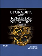
The T-carrier system was developed in the early 1960s by the Bell Telephone System in the United States and was used to digitally transmit voice communications. The first service offered was the T1, which can provide a transmission rate of up to 1.544Mbps. If you need more bandwidth than can be provided by a T1 line, you can contract for a higher level of service, such as a T3 line, which provides a 44.736Mbps connection. The range of transmission rates and number of channels for each kind of T-carrier service are listed in Table 15.1.
Table 15.1. T-Carrier Services in the North American Digital Hierarchy
The T-carrier system is an all-digital transmission system. For voice systems that use a T1 line, the signal is sampled at a rate of 8,000 times per second, and the result is stored in 8 bits, or 1 byte. The T1 provides 24 separate channels that can be used to send voice or data from one place to another using two pairs of wires. Each of the 24 channels can transmit at a rate of 64Kbps.
Note
The European equivalent of the T1 line is called the E-1. Although the two use the same kind of technologies for transmission, the E-1 provides 30 channels and a total bandwidth of 2.045Mbps.
Time-division multiplexing, which allows each channel only a small amount of time to transmit (5.2 milliseconds), is used to combine all 24 channels into one signal. With each channel transmitting at 64Kbps, the total bandwidth on a T1 Channel is 64Kbps×24, or 1.536Mbps. The difference between the 1.536Mbps and the full bandwidth of the T1 pipe (1.544Mbps) is due to the overhead used for managing connections (8Kbps).
Fractional T1
In many cases, the full bandwidth provided by a T1 line is more than the end user requires. Yet a slower 56Kbps leased line might not provide enough bandwidth. To handle this situation, the communications provider allows several users to use the full T1 bandwidth by allocating each user one or more of the 24 channels that T1 provides. This is called Fractional T1.
Diagnosing Problems with T-Carrier Services
When purchasing a T1 or T3 service, the local provider must check out the actual physical line and provide “conditioning” to be sure that it can transmit data at the expected rate with minimal errors. Conditioning means making the line stable enough to provide the service you contract for. Bridge taps and load coils that are normally found on voice-grade lines can’t be used because they can cause the electrical pulses to be slightly out of shape, which makes them unrecognizable by devices on each end of the line. Inadequate grounding of the copper cables and physically defective cables are other sources of problems.
When you request a T-class of service from a local carrier, usually you must wait a few weeks to a few months before the service is operational. If the telephone cables in your area were put in place many years ago, the carrier might have to condition the line by finding and removing bridge taps. New wiring also might have to be run in places where the original cables have degraded over time. All these functions are labor and time intensive.
The distance from the central office to your site also is important when trying to condition a line for any digital service. For example, twisted-pair wiring is normally used in the “last mile” from the central office to your business or home. The farther you are from the central office, the more the electrical signal attenuates. Because of this, the farther you are from the central office, the less bandwidth the wire can provide by the time it reaches you. To solve this problem, many telephone companies have been running fiber-optic cabling out into the field and installing a digital-services box closer to homes and businesses. Because fiber-optic cabling can carry a signal much farther with less attenuation of the signal than can copper wire, this effectively lets the telephone company put a mini central office out in the field. From this digital-services box, ordinary copper wiring can be used to connect to your location.
The loopback capabilities provided by the CSU/DSU unit are used by the provider to check the signal quality on the line. One of the simplest methods for checking the line is the use of a bit error rate tester (BERT). This provides a simple test to determine whether specific bit patterns transmitted by the test equipment can be received back with no distortions. BERT usually is the first test performed and is used to qualify the line as functional after the physical cables have been installed.
When a T1 line is installed, usually it is checked to ensure that all circuits are correctly terminated, which includes checking the user’s equipment (such as the CSU/DSU). Signal loss can indicate that the connection is broken somewhere along the line, the signal being transmitted is too weak, or a connector is faulty.
![]() For more information about BERT, attenuation, and other technical terms commonly used when discussing telephony, see Chapter 6, “Wiring the Network—Cables, Connectors, Concentrators, and Other Network Components,” and Chapter 49, “Network Testing and Analysis Tools.”
For more information about BERT, attenuation, and other technical terms commonly used when discussing telephony, see Chapter 6, “Wiring the Network—Cables, Connectors, Concentrators, and Other Network Components,” and Chapter 49, “Network Testing and Analysis Tools.”
One problem that can occur is called timing jitter. As defined by the ITU-T (Telecommunication Standardization Sector of the International Telecommunications Union), timing jitter refers to “short-term variations of the significant instances of a digital signal from their ideal positions in time.” The signal that is transmitted is a wave form; when viewed on an instrument such as an oscilloscope, you can see the rising and falling edges of the wave. If the wave form is slightly out of sync with the clocking mechanism, the signal might be interpreted by the receiving equipment incorrectly. All T1 circuits have a small degree of jitter, caused mainly by multiplexers or devices along the line that are used to regenerate the signal. Jitter also can be caused by electrical or atmospheric noise (as in the case of microwave transmissions).
Testing the line by using BERT or other instruments that depend on knowing the bit patterns that will be transmitted is called out-of-service testing. Obviously, this can be used only before the customer takes over the line for use. In-service testing, sometimes referred to as quality of service (QoS) testing, cannot make measurements based on expected bit patterns because the data transmitted by the customer can be roughly assumed to be random. Instead, tests performed when the line is already in service involve checking for things such as framing errors, parity errors, or checksum errors, depending on the kind of traffic carried by the line.
Asynchronous Transfer Mode (ATM)
Asynchronous Transfer Mode was developed by AT&T Bell Labs during the 1980s. It is a connection-oriented technology, much like the public telephone system, in which a connection is established between two endpoints before the actual data exchange can begin. ATM can be used in both LAN and WAN environments and provides for full-duplex communication. The fact that many kinds of traffic are being carried on electronic networks today influenced the design of ATM. The PSTN was originally designed to carry voice communications along with other simple services, such as telex (telephone exchange). Today, electronic networks are used to transmit data, voice, and video, and to provide connections for other kinds of multimedia applications.
In an attempt to design a one-size-fits-all network and provide for new kinds of traffic in the future, ATM uses a fixed packet size of 53 bytes (48 bytes for the payload and 5 bytes for the header) to transmit data. In referring to a packet of data in ATM networks, the term cell is normally used. The advantage to using a fixed-length cell as opposed to a variable-length packet such as that used by Frame Relay—discussed later in this chapter—is that hardware devices that switch network traffic usually can be designed to operate at higher speeds when switching fixed-length packets of information. The algorithm can be implemented with less complex code and hardware design because the switch that routes cells through an ATM network doesn’t have to perform calculations to determine where one packet stops and another begins, which is the case in Frame Relay networks where packet size is not fixed.
The small header also means that the switch must process much less information for each packet. There are two kinds of ATM frame headers, but both are 5 bytes. During the development of ATM, some argued for a smaller cell size of 32 bytes, which would provide a better quality voice service. Others argued for a cell size of 64 bytes, which would provide more efficient data-delivery services. The 48-byte payload was finally chosen as a compromise. Add that to the 5-byte header, and you have a fixed-cell size of 53.
ATM Frames
ATM has two types of frame headers. The first is the User-Network Interface (UNI) header, which is used for ATM cells that travel between an endpoint in the connection—such as a standard network router or perhaps a PC or high-end workstation equipped with an ATM network card—and the ATM switch. This frame type, shown in Figure 15.2, consists of 5 bytes divided into eight fields.

Figure 15.2. Note the contents of the ATM UNI cell header.
The fields of the UNI cell header are as listed here:
![]() GFC (Generic Flow Control)—This frame headers. The first is the 4-bit field isn’t generally used any more, but you might find it used with local significance for identifying individual computers on the network or for traffic-control functions. The default value for this field is four 0 bits.
GFC (Generic Flow Control)—This frame headers. The first is the 4-bit field isn’t generally used any more, but you might find it used with local significance for identifying individual computers on the network or for traffic-control functions. The default value for this field is four 0 bits.
![]() VPI (Virtual Path Identifier)—This 8-bit field specifies a value that identifies the virtual path for a stream of cells. The VPI, used in conjunction with the next field, identifies a connection set up through the network of switches. A value of 0 in this VPI field means that the cell is being used for network administrative purposes, such as call setup or terminations.
VPI (Virtual Path Identifier)—This 8-bit field specifies a value that identifies the virtual path for a stream of cells. The VPI, used in conjunction with the next field, identifies a connection set up through the network of switches. A value of 0 in this VPI field means that the cell is being used for network administrative purposes, such as call setup or terminations.
![]() VCI (Virtual Channel Identifier)—This 16-bit field is used with the VPI to identify a path through the switched network. As explained later, many cells that have different values in the VCI field can have the same VPI value. Although up to 65,536 values can be stored in a 16-bit field, values 0–15 are reserved for use by the ITU, and values 16–32 are reserved by the ATM Forum for various signaling and management operations.
VCI (Virtual Channel Identifier)—This 16-bit field is used with the VPI to identify a path through the switched network. As explained later, many cells that have different values in the VCI field can have the same VPI value. Although up to 65,536 values can be stored in a 16-bit field, values 0–15 are reserved for use by the ITU, and values 16–32 are reserved by the ATM Forum for various signaling and management operations.
![]() PT (Payload Type)—The first bit in this 3-bit field indicates whether the packet contains user data (value = 0) in the payload section of the cell or whether the payload section contains control data (value = 1). If the cell contains user data, the second bit can be used to report network congestion. The second bit is set to 0 by the source and is set to 1 by a switch that is experiencing congestion. The destination endpoint then can use flow-control mechanisms to throttle back transmissions until it receives cells with a value of 0 in this bit. The third bit is used to indicate that this is the last cell in a series of cells that make up an AAL5 user frame. For nonuser cells, this value is used for administrative purposes.
PT (Payload Type)—The first bit in this 3-bit field indicates whether the packet contains user data (value = 0) in the payload section of the cell or whether the payload section contains control data (value = 1). If the cell contains user data, the second bit can be used to report network congestion. The second bit is set to 0 by the source and is set to 1 by a switch that is experiencing congestion. The destination endpoint then can use flow-control mechanisms to throttle back transmissions until it receives cells with a value of 0 in this bit. The third bit is used to indicate that this is the last cell in a series of cells that make up an AAL5 user frame. For nonuser cells, this value is used for administrative purposes.
![]() CLP (Cell Loss Priority)—When congestion in the network makes it necessary to drop cells, those with a value of 1 in this single-bit field are the primary candidates to be dropped as compared to those with a value of 0 in this field.
CLP (Cell Loss Priority)—When congestion in the network makes it necessary to drop cells, those with a value of 1 in this single-bit field are the primary candidates to be dropped as compared to those with a value of 0 in this field.
![]() HEC (Header Error Control)—This 8-bit field is used to store a CRC value that can be used to detect whether the cell becomes corrupted during transport.
HEC (Header Error Control)—This 8-bit field is used to store a CRC value that can be used to detect whether the cell becomes corrupted during transport.
The second kind of ATM cell header is the Network-Node Interface (NNI) format. NNI is used for transmissions between the switches that make up the ATM network, which, as you can see in Figure 15.3, is similar to the UNI cell header.

Figure 15.3. Note the contents of the ATM NNI cell header.
The main difference from the UNI header is that the NNI cell doesn’t have the GFC field. The other fields are there; the VPI field has grown from 8 bits to 12 bits, which can provide for up to 4,096 virtual paths through the network.
ATM Connections
Connections created between endpoints in the ATM network can be either permanent virtual connections (PVCs) or switched virtual connections (SVCs). Each switch in the ATM network keeps track of connections using routing tables, and decisions are made based on the information in the 5-byte header. Because the switch does not have to make any decisions based on the service data contained in the cell’s payload section, hardware-based switches can quickly route and transport cells to their destinations.
ATM provides two kinds of transport connections: virtual channels and virtual paths. A virtual channel is used for an individual connection through the network. The virtual channel identifier (VCI) is used to identify cells in this connection. A virtual path is made up of multiple virtual channels that all share a common path through the network; it is identified in the cell header by a virtual path identifier (VPI). When connections are grouped using VPIs, management and controlling functions must be performed only once for a group of individual connections (using the VPI), making the network operate more efficiently.
However, the values for the VPI/VCI fields do not remain the same when the cells travel through ATM switches. When a cell is received on one port of the switch, the VPI/VCI fields are used to perform a lookup in the routing table. When a match is found, the new VPI/VCI values are inserted into the cell and it is transmitted out on a port that gets it to its eventual destination, based on the path created during call setup (or as determined by the administrator for a PVC). To put it another way, VPI/VCI values have local significance only for the particular connection.
Before any data can be exchanged, the virtual connection path must be determined. Similar to the mechanism used in the telephone network, the path through the network from one switch to another switch is predetermined before any data exchange takes place. In determining the path that the connection will use, the quality of service for the traffic is taken into consideration to ensure that a path will be created that can provide the bandwidth needed by the service. Traffic is policed to ensure that a particular connection does not abuse the network by using resources to which it is not entitled.
The ATM Architecture Model (B-ISDN/ATM Model)
The basic architecture used for ATM involves three layers: Physical layer, ATM layer, and ATM Adaptation layer (see Figure 15.4).
Figure 15.4. The ATM architecture model.
As you can see in this figure, the Physical layer is further subdivided into the Physical Medium Dependent (PMD) sublayer and the Transmission Convergence (TC) sublayer. The ATM Adaptation layer is further divided into the Segmentation and Reassembly (SAR) sublayer and the Convergence sublayer (CS).
The Physical Layer
The two components of the Physical layer are responsible for the actual transmission of cells across the network. Signal encoding and interfacing with the network transmission media (such as copper wire or fiber-optic cables) are performed by the PMD. By keeping the physical aspects of the protocol as a separate component, it is possible to define many kinds of PMDs for ATM. Thus, it’s easy to create a PMD to allow ATM to operate over many types of physical networks.
The TC component of the physical layer interfaces with the ATM layer and is responsible for taking the stream of bits supplied by that layer and mapping the ATM cells onto the PMD-specific frame. For example, if the underlying network is SONET, the TC component maps the ATM fixed-length cells onto SONET frames and then passes these to the SONET PMD.
The ATM Layer
The VPI/VCI routing functions and flow control mechanisms are implemented on the ATM layer. Remember that the combination of VPI/VCI allows for multiplexing many connections across a common virtual circuit. The ATM layer is responsible for this multiplexing-demultiplexing functionality. This layer also can monitor connections and take corrective action if it finds that a connection is not performing within the boundaries that were negotiated during call setup. Routing functions use the VPI/VCI to ensure that the cells travel over the proper connection between the connection’s endpoints. However, similar to the Internet Protocol (IP), the ATM layer does not provide for error control. If packets are dropped at a switch along the connection’s path, it’s up to higher-level protocols to recognize this and take the necessary actions to retransmit the data.
The ATM Adaptation Layer (AAL)
The AAL is responsible for packaging the data on the sending part of the connection into 48-byte payloads, and for unpacking the data and reassembling it into larger messages on the receiving end. For example, an IP datagram handed down by the IP protocol will be larger than the payload size that the ATM cell can handle. In the ATM Adaptation layer, this larger message is fragmented into smaller payloads and sent down to the Physical layer for transmission in ATM cells. At the receiving end of the connection, the individual payloads are reassembled back into the larger message and passed up to a higher-level network protocol.
In the Convergence sublayer (CS), a protocol data unit (PDU) from a higher-level protocol is encapsulated into a format so that it can be reassembled into that same format at the receiving end. In the Segmentation and Reassembly (SAR) sublayer, the data is divided into 48-byte payloads. These payloads then are passed to the ATM layer, which attaches the header to create the 53-byte cell.
Several ATM adaptation layers have been defined by the ITU-T:
![]() AAL0—This adaptation layer was created to provide for a user-defined layer. Basically, the 48-byte payloads are passed up and down the protocol stack when sending or receiving data.
AAL0—This adaptation layer was created to provide for a user-defined layer. Basically, the 48-byte payloads are passed up and down the protocol stack when sending or receiving data.
![]() AAL1—This adaptation layer was created to provide for a time-dependent, constant bit-rate service for connection-oriented applications. AAL1 is usually found in voice or video applications and includes a higher amount of overhead when compared to other adaptation layers. For example, time stamps and error checking can be added to the payload section of the cell.
AAL1—This adaptation layer was created to provide for a time-dependent, constant bit-rate service for connection-oriented applications. AAL1 is usually found in voice or video applications and includes a higher amount of overhead when compared to other adaptation layers. For example, time stamps and error checking can be added to the payload section of the cell.
![]() AAL2—This adaptation layer was created to provide a variable bit-rate service for connection-oriented applications. AAL2 is used for compressed video and voice, for example.
AAL2—This adaptation layer was created to provide a variable bit-rate service for connection-oriented applications. AAL2 is used for compressed video and voice, for example.
![]() AAL3/4—These two adaptation layers offer a variable bit-rate service for connection-oriented (was AAL3) or nonconnection-oriented (was AAL4) applications, such as LAN traffic. Although originally defined as two separate adaptation layers, it is now a single entity. A small amount of overhead data (such as segment size and sequencing numbers) is added to the payload section of the ATM cell.
AAL3/4—These two adaptation layers offer a variable bit-rate service for connection-oriented (was AAL3) or nonconnection-oriented (was AAL4) applications, such as LAN traffic. Although originally defined as two separate adaptation layers, it is now a single entity. A small amount of overhead data (such as segment size and sequencing numbers) is added to the payload section of the ATM cell.
![]() AAL5—This adaptation layer gives a variable bit-rate service similar to AAL3/4 but has a lower overhead than AAL3/4. AAL5 is normally used for LAN traffic such as IP. AAL5 improves over AAL3/4 by adding a trailer to the data to be transferred that provides for error checking and specifies the size of the payload.
AAL5—This adaptation layer gives a variable bit-rate service similar to AAL3/4 but has a lower overhead than AAL3/4. AAL5 is normally used for LAN traffic such as IP. AAL5 improves over AAL3/4 by adding a trailer to the data to be transferred that provides for error checking and specifies the size of the payload.
Of these layers, AAL5 was created specifically to make ATM an attractive choice for typical LAN applications. The AAL5 frame format is composed of several fields that are made up of the actual payload, followed by the AAL5 trailer fields:
![]() Payload—The payload field contains the actual application data and can range in size from 1 byte up to 65,535 bytes in length.
Payload—The payload field contains the actual application data and can range in size from 1 byte up to 65,535 bytes in length.
![]() Pad—This field, which can range from 0 to 47 bytes in length, is used for padding (adding zeros) to the frame to ensure that the total frame (or PDU) can be evenly divided into the 48-byte payloads created by the SAR sublayer.
Pad—This field, which can range from 0 to 47 bytes in length, is used for padding (adding zeros) to the frame to ensure that the total frame (or PDU) can be evenly divided into the 48-byte payloads created by the SAR sublayer.
![]() User to User Indication—This single-byte field is basically undefined and left up to the implementation.
User to User Indication—This single-byte field is basically undefined and left up to the implementation.
![]() Common Part Indicator—This single-byte field is used for alignment processes to be sure that the AAL5 trailer is on a 64-bit boundary.
Common Part Indicator—This single-byte field is used for alignment processes to be sure that the AAL5 trailer is on a 64-bit boundary.
![]() Length of Payload—This 2-byte field specifies the length of the payload field. Length of Payload does not include any padding bytes, so it can be used by the receiving end to determine where the actual payload ends and padding begins.
Length of Payload—This 2-byte field specifies the length of the payload field. Length of Payload does not include any padding bytes, so it can be used by the receiving end to determine where the actual payload ends and padding begins.
![]() CRC—This 4-byte field is used to store a CRC value to ensure the integrity of the entire PDU being transmitted. It is not a calculation on the contents of any individual ATM cell, but applies to the message that is being broken into fragments for transmission in ATM’s 48-byte payloads.
CRC—This 4-byte field is used to store a CRC value to ensure the integrity of the entire PDU being transmitted. It is not a calculation on the contents of any individual ATM cell, but applies to the message that is being broken into fragments for transmission in ATM’s 48-byte payloads.
If you’ll remember, the third bit of the Payload Type Indicator field of the ATM header is used to specify that the cell is the last cell of a message (or PDU) that was broken down into 48-byte payloads. Thus, larger messages from higher-level protocols (such as IP) can be identified and reassembled while passing through the ATM network of switches in simple, short, 48-byte payloads.
LAN Emulation (LANE)
ATM was originally designed to be a wide area networking protocol. However, local area networks have changed dramatically in the past few years. Whereas a simple 10BASE-T network might have provided sufficient bandwidth a few years back, you now see LANs composed of, or connected by, much faster links, such as Gigabit Ethernet and 10 Gigabit Ethernet.
Speed is not the only thing that’s changed in the local area networking scene. The LAN that was used for simple file and print sharing now must support various applications. For example, videoconferencing is becoming a common application in the LAN. In a traditional LAN, however, you can’t “reserve” or “guarantee” that the bandwidth needed to support such an application will always be available.
Using ATM in a LAN can help reduce congestion if the network consists of multiple kinds of traffic, such as one that supports workstations and file servers along with multimedia applications. If you use ATM as a backbone, you can interface it with your normal Ethernet or Token-Ring segments. The ATM Forum has published specifications for LANE to define the approach to be taken for using ATM in the LAN environment. LANE specifies how other traditional LAN protocols—such as Ethernet (IEEE 802.3) and Token-Ring (IEEE 802.5)—are to be carried over ATM.
The LANE protocol was developed to allow a LAN to be emulated using ATM. That is, LANE makes an ATM switched network look to the client computer just like a typical LAN. LANE consists of the following:
![]() LAN Emulation Client—This software interfaces between the traditional client’s LAN software and ATM. To the client’s LAN software, the LAN Emulation Client appears to operate just like the local LAN. To the ATM network to which the client is connected, the LAN Emulation Client performs the necessary ATM functions.
LAN Emulation Client—This software interfaces between the traditional client’s LAN software and ATM. To the client’s LAN software, the LAN Emulation Client appears to operate just like the local LAN. To the ATM network to which the client is connected, the LAN Emulation Client performs the necessary ATM functions.
![]() LANE Services—This component of LANE provides for translating between traditional LAN addresses and ATM addresses.
LANE Services—This component of LANE provides for translating between traditional LAN addresses and ATM addresses.
LANE can be used with Ethernet and Token-Ring networks to provide a faster connection for your LAN because all traffic is sent through ATM switches. You can find many ATM switches that include support for LANE, or, as is the case with Windows 2000 or Windows Server 2003, the LAN Services component can reside on a Windows 2000/2003 Server.
IP over ATM
For most implementations, you’ll find that AAL5 is used to send IP datagrams over ATM. The relevant RFC documents are RFC 1577, “Classical IP and ARP over ATM,” and RFC 1626, “Default IP MTU for use over ATM AAL5.” RFC 1577 doesn’t define how ATM networks function, but provides instead a method for IP and address resolution mechanisms over an ATM network. RFC 1626 defines the value of 9,180 bytes as the default Maximum Transmission Unit (MTU) size for IP datagrams on an ATM network. It also discusses how, during call setup for a switched virtual circuit, the actual MTU size used for the connection can be negotiated.
When IP datagrams are sent over an ATM connection, the AAL5 trailer information is added to the end of the datagram and then passed to the SAR sublayer for division into the 48-byte payloads required for ATM. As explained in the preceding section, when the cell containing the last part of the IP datagram is created, the third bit of the PT (Payload Type) is set to 1 so that the endpoint recognizes that it now has all the information necessary to reassemble the smaller payloads into the original IP datagram.
IP over ATM has several advantages that make it a better choice for IP networks than LANE. First, LANE doesn’t support the QoS capabilities of ATM, which you’ll learn about in the next section. Second, IP over ATM has a lower overhead, so more bandwidth is available for transmitting actual data. Windows 2000 and Windows Server 2003 also support IP over ATM. Because of this, IP over ATM usually is faster than LANE.
Similar to LANE, the IP over ATM software interfaces between the TCP/IP protocol stack and the ATM network.
ATM Service Categories
Although early implementations of ATM use the technique of reserving a specified, fixed amount of bandwidth for a connection in advance, service categories now allow for several levels of service that can be matched to the needs of different types of traffic. Each level of service defines the network behavior for a different kind of network traffic that can be used to specify the QoS required for certain kinds of applications. For example, some network applications require precise timing and cannot tolerate excessive delays or reductions in bandwidth (such as video transmissions). Other applications tend to make bursty requests when bandwidth requirements vary widely in just a short time (such as file transfers).
The following service categories are presently defined by the ATM Forum:
![]() Constant Bit Rate (CBR)
Constant Bit Rate (CBR)
![]() Real-Time Variable Bit Rate (rt-VBR)
Real-Time Variable Bit Rate (rt-VBR)
![]() Non–Real-Time Variable Bit Rate (nrt-VBR)
Non–Real-Time Variable Bit Rate (nrt-VBR)
![]() Available Bit Rate (ABR)
Available Bit Rate (ABR)
![]() Unspecified Bit Rate (UBR)
Unspecified Bit Rate (UBR)
The CBR category is based on providing a constant maximum bandwidth allocation for the connection for time-sensitive applications. The application does not always have to use the maximum bandwidth, but the maximum is available if needed for this level of service. This service category is suitable for use by real-time applications, voice and video applications, videoconferencing, and other similar applications.
The rt-VBR service category also is meant to provide a high level of service for time-sensitive applications that do not always maintain a constant bit rate but are still time-sensitive applications.
The nrt-VBR service category is similar to the rt-VBR category in that the expected traffic will be bursty in nature, but the nature of the communications does not require that data be delivered without significant delays. Both VBR categories can be useful for applications such as voice, when compression techniques are used, and possibly transaction-based applications, such as reservation systems or for carrying Frame Relay traffic.
The ABR category is intended for applications that might increase or decrease their traffic level depending on network conditions. In other words, they can be satisfied by using whatever bandwidth is available. Connections of this type can specify a minimum required bandwidth level but then can use more bandwidth as the network makes it available. Typical uses for this kind of service are LAN connections, such as distributed file services.
The UBR service category represents a “best effort” connection and is intended for applications that really don’t care about bandwidth or QoS. This bottom-of-the-barrel kind of service is useful for applications with traffic that needs to get from one place to another but is in no hurry; for example, file transfers that can be done in a batch mode and do not have users sitting at the keyboard waiting for completion. Messaging services, such as email, also might find this service level sufficient.
The Importance of Frame Relay and the X.25 Interface
The X.25 protocol defines an interface for delivering information to a packet-switched network and does not make any assumptions about the method used to carry the actual data from one place to another. Or, to put it another way, X.25 is not a transport protocol. It is an interface that can be adapted to different kinds of network transport protocols. X.25, which has been around for more than 20 years, was developed to allow connection to various public networks, such as CompuServe and Tymnet, and it provides for speeds of up to 56Kbps. Frame Relay is similar to X.25 except that it uses digital connections instead of the analog connections that X.25 was designed for. Although X.25 can be considered a “dying” technology, Frame Relay use continues to grow.
Frame Relay can operate at much higher speeds (up to 1.544Mbps) than X.25 because of the digital nature of Frame Relay, which is usually offered over a T1 or fractional T1 line. The digital nature of the line allows fewer errors than the analog system, and Frame Relay can operate faster than other technologies because it does not perform any actual error correction. When a frame error is detected, the frame is dropped. It is up to the endpoints to detect, through some higher-level protocol, that an error has occurred.
If an error is found in the frame, or if the network is too busy, the frame is dropped. This is similar to the way the IP functions. Frame Relay does its best to get the frame to its endpoint in the connection, but it does not notify the starting point of the connection if an error occurs. Because Frame Relay doesn’t have to worry about reporting errors (which can occur anywhere along the path, at any switch) back to the sender, it can switch traffic at a faster rate. With today’s fast CPUs and digital lines (which are less prone to errors than analog lines), it only makes sense to let higher-level protocols take care of detecting and remedying errors.
Because Frame Relay is a packet-switched technology, you must pay for only the bandwidth you expect to use. Instead of paying for the full cost of a T1 line between two geographically distant offices, you can use Frame-Relay services. The carrier mixes traffic from various sources and transmits it over the line so that Frame Relay represents a shared-medium technology. The downside is that it’s always possible that the bandwidth you need might not be available when you need it. Just as you sometimes get a circuit-busy message when you try to place a telephone call during a peak holiday period, the same thing can happen if traffic from multiple users of a carrier’s Frame-Relay service must transfer large amounts of data at the same time.
For this reason, when you purchase Frame-Relay services, you get a guarantee—called the committed information rate (CIR)—of the amount of available bandwidth that the carrier expects to be capable of providing. You might be able to get higher throughput rates than that guaranteed by the CIR, but there is always the possibility that, occasionally, you might not achieve rates that are guaranteed by the CIR. It is important to monitor your use in a high-traffic environment to be sure you are getting what you paid for.
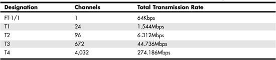
Frame Relay also can reduce the number of physical connections you need at a site, which can make it a better choice than dedicated point-to-point lines. For example, if you have multiple branch offices, you could use a dedicated T1 (or Fractional T1) line to connect each office to the main headquarters. Or you could use Frame Relay at each branch office, using only a single physical connection back at the main office. Traffic from all the branch offices is lumped together on this incoming Frame Relay line, so you don’t need a separate physical dedicated line going to each branch office (see Figure 15.5).
Figure 15.5. Using Frame Relay can reduce the number of physical connections required when compared to dedicated lines.
Frame Relay is similar to ATM in that it is a packet-switched technology. However, ATM uses a fixed sized for its cells, whereas Frame Relay packets are variable (similar to Ethernet frames). Packet switching in a Frame Relay network is done using virtual circuits, which are logical paths through the Frame Relay network.
Note
Some vendors of Frame-Relay services offer much faster capabilities, up to 45Mbps, using T3 lines.
The Frame Relay Header
Frame Relay also has a lower overhead than traditional network technologies, such as Ethernet. The Frame Relay header is only 2–5 bytes long. In Figure 15.6, you can see that the header doesn’t contain a whole lot of information.
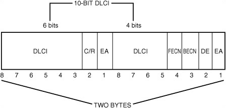
Figure 15.6. The Frame Relay header contains the DLCI (Data Link Connection Identifier) that identifies the connection.
The following fields appear in Figure 15.6:
![]() DLCI—The Data Link Connection Identifier is used to identify the virtual circuit connection. Note that the DLCI is 10 bits long but is not stored contiguously in the header.
DLCI—The Data Link Connection Identifier is used to identify the virtual circuit connection. Note that the DLCI is 10 bits long but is not stored contiguously in the header.
![]() C/R—The single-bit Command/Response field is application specific. Network switches do not modify this field.
C/R—The single-bit Command/Response field is application specific. Network switches do not modify this field.
![]() FECN—This single-bit field is the Forward Explicit Congestion Notification field.
FECN—This single-bit field is the Forward Explicit Congestion Notification field.
![]() BECN—This single-bit field is the Backward Explicit Congestion Notification field.
BECN—This single-bit field is the Backward Explicit Congestion Notification field.
![]() DE—This single-bit field is the Discard Eligibility Indicator field.
DE—This single-bit field is the Discard Eligibility Indicator field.
![]() EA—This single-bit field is the Extension Bit, which is used to indicate a 3- or 4-byte header.
EA—This single-bit field is the Extension Bit, which is used to indicate a 3- or 4-byte header.
The DLCI field is a 10-bit number used to specify the virtual circuit number for the connection. The DLCI identifies the particular port to which the local network is attached in the Frame Relay equipment. Throughout the network, this number is used to designate the endpoint of the connection.
When using a PVC, the network administrator must set up routing tables in the switches that make up the network. When a frame comes in one port, it is a simple matter to look up the DLCI in a table and then quickly switch the frame to an outgoing port that can take it to another switch, where the process is repeated, or to its eventual destination. Note that if a switch receives a frame that has a DLCI value that is not found in the switch’s routing table, the frame is discarded.
If this sounds like a simple mechanism for getting a data frame from one point to another, it is. In addition to the short header, the Frame Relay packet also has a frame check sequence (FCS) value calculated to ensure the integrity of the packet, which is placed at the end of the frame. The switch can recalculate this value when it receives a frame and, if the newly calculated value does not match the value stored in this field, the frame is assumed to have become corrupted and is dropped.
Network congestion also can cause a packet to be dropped. After a switch’s buffers are full, incoming frames are dropped until buffer space becomes available again. However, Frame Relay does provide some signaling mechanisms that can be used to help control network congestion. Frame Relay also provides for signaling to set up an SVC. Both of these signaling mechanisms, however, are optional components and vendors don’t have to implement them. Remember that the higher-level protocol (such as TCP/IP) can detect when its data segments have not been acknowledged and retransmit any data that is dropped along the virtual circuit path.
Network Congestion Signaling
Three methods can be used to help prevent network congestion:
![]() Explicit Congestion Notification
Explicit Congestion Notification
![]() Discard Eligibility
Discard Eligibility
![]() Implicit Congestion Notification
Implicit Congestion Notification
The Explicit Congestion Notification method uses 2 bits in the header: the FECN (Forward Explicit Congestion Notification) and BECN (Backward Explicit Congestion Notification) bits. The FECN bit is used to tell nodes farther along the path (forward) that congestion is occurring. Based on such things as the switch’s buffer use and the length of frames waiting in a queue, a switch can detect that congestion probably is going to occur before it must start dropping packets. When this happens, the switch sets the FECN bit in a packet to 1 (the default is 0) and then sends the packet on to the next switch. In this manner, switches downstream from the switch approaching congestion are notified of the condition.
Similarly, the BECN bit is used to notify upstream sources that a network congestion condition is rapidly becoming a possibility. It does this not by returning packets sent from that source, but by watching for packets traveling in the opposite direction that are already addressed to that source. The BECN bit is set to 1 (again, the default is 0) in these packets. Thus, when a source sending out a lot of traffic starts to receive packets back from other switches, it can check this bit to determine whether packets are being transmitted too fast.
Implicit Congestion Notification is not performed by the Frame Relay switches. Instead, it means that the higher-level protocols, such as TCP, can detect that packets are not being acknowledged, take appropriate action to retransmit them, and, depending on the higher-level protocol, possibly slow down the transmission rate.
Referring to Figure 15.6, notice that another field, Discard Eligibility (DE), also can be present in a Frame Relay packet. This field is used to determine which packets should be dropped when a congestion condition occurs. Remember that the Frame Relay provider contracts to give you a CIR. Yet when the network is not busy, usually you can use more bandwidth. However, after you begin to send out data at a rate that is greater than the CIR you have contracted for, the DE bit is set to 1 (the default is 0).
When a switch needs to drop packets due to network congestion, those packets that have the DE field set to 1 are the first to go! If discarding those packets doesn’t solve the problem, any packet can be dropped. When properly implemented, however, this mechanism lets a switch drop packets that probably are the source of the congestion in the first place: those that are sending at a rate above their contracted CIR.
The Local Management Interface Signal Mechanism
Another optional signaling mechanism that can be used in a Frame-Relay network is called the Local Management Interface (LMI) specification, of which there are several versions. However, the basic mechanism employed is to use nondata management frames to report the status of an interface or a virtual circuit. For example, a management frame can be used to send a keepalive signal, indicating that, although there isn’t a lot of traffic flowing through the interface, the connection is still active. Another management frame can be used to report on the valid DLCIs for a particular interface. Finally, a management frame can be used to indicate the status of a virtual circuit (it’s congested, for example).
Using Switched Virtual Circuits (SVCs)
Originally, most Frame Relay equipment was made to allow for the creation of PVCs. This requires that a network administrator of the Frame-Relay network set up routing tables so that a permanent connection exists between the two endpoints of a connection. This is a general principle, in that alternative routes can be used occasionally, but basically a PVC is an always-on, same-path type of connection.
An SVC is more like a telephone call; it’s an on-demand path created for the duration of the datatransfer session. After it has been used, the virtual circuit is torn down and doesn’t stay in a switch’s routing table like the DLCI entries for a PVC. When an SVC needs to be created, the destination is notified of the need, and, if it is willing to accept the circuit, a path is created through the Frame-Relay network for the SVC (call setup). When the circuit is no longer needed, either side of the connection can notify the network to terminate the circuit.
The advantage of using an SVC is that you have to pay only for what you use. It’s less expensive than maintaining a PVC that doesn’t have a constant rate of traffic. SVCs also can be used in conjunction with PVCs. You can use PVCs for your basic network traffic that flows at a predictable rate, and create or tear down SVCs as needed to handle additional traffic.
The methods used for signaling to set up and terminate SVCs is beyond the scope of this book, and this is a subject that should be pursued if you are an administrator of a Frame-Relay network. For the end user, however, the mechanisms used for call setup and termination aren’t that important. You might want to visit the Frame Relay Forum’s Web site, which contains a wealth of information on the technical details involved in signaling, as well as documents about proposed new methods and features for Frame-Relay networks.
Possible Problems Using Frame Relay
You might encounter the following problems when using Frame Relay:
![]() Bandwidth use—As you grow, you might find that the amount of bandwidth you purchased is inadequate for your needs.
Bandwidth use—As you grow, you might find that the amount of bandwidth you purchased is inadequate for your needs.
![]() Bursting—When you try to send a large burst of traffic that is in excess of the contracted rate, the switch might discard packets it receives that are above the allowable rate, forcing retransmissions and increased response times.
Bursting—When you try to send a large burst of traffic that is in excess of the contracted rate, the switch might discard packets it receives that are above the allowable rate, forcing retransmissions and increased response times.
![]() Network congestion—Although the vendor might give you a guarantee of the available bandwidth (the CIR), when many customers use the network at the same time, network congestion can result.
Network congestion—Although the vendor might give you a guarantee of the available bandwidth (the CIR), when many customers use the network at the same time, network congestion can result.
The Frame Relay Forum defined several metrics that can be used to determine the quality of service in a Frame-Relay network. These metrics, which can be found in the forum’s FRF.13 Service Level Definitions Implementation Agreement, are listed here:
![]() Frame Transfer Delay—The time required to transfer a frame through the network.
Frame Transfer Delay—The time required to transfer a frame through the network.
![]() Frame Delivery Ratio—The ratio of frames received (frames delivered) to the number of frames sent (frames offered) in one direction across a single virtual connection.
Frame Delivery Ratio—The ratio of frames received (frames delivered) to the number of frames sent (frames offered) in one direction across a single virtual connection.
![]() Data Delivery Ratio—Similar to the Frame Delivery Ratio, but measures the ratio of payload octets received to those sent.
Data Delivery Ratio—Similar to the Frame Delivery Ratio, but measures the ratio of payload octets received to those sent.
![]() Service Availability—Outages resulting from faults in the network (called Fault Outage) as well as those beyond the control of the network, including scheduled maintenance (called Excluded Outage).
Service Availability—Outages resulting from faults in the network (called Fault Outage) as well as those beyond the control of the network, including scheduled maintenance (called Excluded Outage).
When reviewing the Service Level Agreement (SLA) that your Frame-Relay provider offers, use these metrics to help you understand what kind of commitment the vendor is making. With these metrics, the vendor might further qualify them based on the CIR as opposed to bursts allowed by the agreement. For example, it would be unreasonable to expect to receive the same kind of delivery ratio for bursts of high-volume traffic that you receive for traffic that flows through the network at the rate guaranteed by the CIR.
When you review the SLA, be sure you understand how each metric will be measured. Does the vendor use statistics provided by its own switch (and will the vendor allow you access to these statistics?), or does the vendor use an RMON probe or SNMP MIB to define the metrics? What portion of the connection is to be measured for metrics: end-to-end or switch to switch?