
Chapter Fifteen. Drawing Control and Data Management
Objectives
After studying the material in this chapter, you should be able to:
1. Present the rationale for controlling engineering documents.
2. Describe the role of the drawing or CAD file in engineering documentation.
3. List the basic steps in approving and controlling CAD data.
4. Organize your files and directories in a consistent manner.
5. Practice good file handling and backup procedures.
6. Describe the basic principles of product data management.
Refer to the following standards:
• ASME Y14.42 Digital Approval Systems
• ASME Y14.100 Engineering Drawing Practices
• ASME Y14.41 Digital Product Definition Data Practices

SolidWorks PDM offers a realistic view of each part so users can quickly identify and select a component from within an assembly. Notice the menu options for checking in and checking out the component. This ensures that two different people are not modifying the same part. The software provides many document control features, including the ability to track who made changes to a part or assembly.
Documentation and the Design Database
Companies using computer-aided design tools must address issues of document management. When paper drawings were used throughout the design process as well as for documentation, practices for approving and releasing drawings, making drawing changes, and distributing and storing drawings were developed over time to fit the use of “hard copy” as a medium. With the advent of design databases stored on computer systems, these practices were updated to use electronic files. Companies had to adapt their practices from paper drawings to electronic files to retain their engineering design records in a systematic and permanent way.
Companies must also address document sharing issues. Concurrent engineering depends on the ability of a team of individuals to work together on interrelated tasks and with the design database. The team’s access to current and accurate information is crucial to its members’ ability to work simultaneously on different aspects of the same project. Managing the flow of design database information to and among members of the team is a contemporary aspect of drawing control.
Today’s commercial systems use a central database to store and serve data to a wide range of other software tools. Whether you work at a large or small company, you need to be aware of the issues in document management and the tools being developed to save you time and facilitate your involvement in team-based concurrent engineering.
Drawing Management in Engineering Ethics

The Hyatt Regency Walkways Collapse provides a vivid example of the importance of accuracy and detail in engineering design and shop drawings (particularly regarding revisions), and the costly consequences of errors.
On July 17, 1981, the Hyatt Regency Hotel in Kansas City, Missouri, held a videotaped tea-dance party in their atrium lobby. With many party-goers standing and dancing on the suspended walkways, connections supporting the ceiling rods that held up the second and fourth-floor walkways across the atrium failed, and both walkways collapsed onto the crowded first-floor atrium below. The fourth-floor walkway collapsed onto the second-floor walkway, while the offset third-floor walkway remained intact. The collapse left 114 dead and in excess of 200 injured. Millions of dollars in costs resulted from the collapse, and thousands of lives were adversely affected. The ensuing investigation of the accident revealed some unsettling facts.
During January and February 1979, the design of the hanger rod connections was changed in a series of events and disputed communications between the fabricator (Havens Steel Company) and the engineering design team (G.C.E. International, Inc., a professional engineering firm). The fabricator changed the design from a one-rod to a two-rod system to simplify the assembly task, doubling the load on the connector, which ultimately resulted in the walkways’ collapse.
The fabricator, in sworn testimony after the accident, claimed that his company (Havens) telephoned the engineering firm (G.C.E.) for change approval. G.C.E. denied ever receiving such a call from Havens.
On October 14, 1979 (more than one year before the walkways collapsed), while the hotel was still under construction, more than 2700 square feet of the atrium roof collapsed because one of the roof connections at the north end of the atrium failed.
In testimony, G.C.E. stated that on three separate occasions they requested on-site project representation during the construction phase; however, these requests were not acted on by the owner (Crown Center Redevelopment Corporation), owing to additional costs of providing on-site inspection.
Even as originally designed, the walkways were barely capable of holding up the expected load and would have failed to meet the requirements of the Kansas City Building Code.
Owing to evidence supplied at the hearings, a number of principals involved lost their engineering licenses, several firms went bankrupt, and many expensive legal suits were settled out of court. The case serves as an excellent example of the importance of meeting professional responsibilities and what the consequences are for professionals who fail to meet those responsibilities.
(Excerpted from “Negligence, Risk and the Professional Debate over Responsibility for Design” A Case History of the Kansas City Hyatt Regency Walkways Collapse. Department of Philosophy and Department of Mechanical Engineering, Texas A&M University.)
15.1 Requirements for Engineering Documentation
The information contained in the 3D design database used to produce drawings and to send files for NC machining, mold design, or other manufacturing processes is an important part of the engineering design record. The ASME standard Y14.41, Digital Product Definition Data Practices, outlines documentation practices for digital designs and types of digital data that may be associated with them. This standard augments traditional documentation practices developed for paper drawings to encompass all the design information companies must manage.
Companies must manage the design record so they can produce documentation for various purposes, such as defending themselves against product safety liability and patent infringement lawsuits. In the event of legal issues, you must be able to produce the document as it existed and in a method that is admissible in a court of law. Because electronically stored files can be altered, they may not be considered an acceptable method for documenting engineering designs unless there is a clear process in place for storing and managing the digital data. In addition, most legal requests are for copies of all versions of the design, and all copies stored and used within the company. It can be costly and embarrassing if they are not well organized and correct, or if there are multiple versions in use that vary from one to the other.
Legal standards for the length of time engineering drawings need to be retained vary from state to state and industry to industry. In most cases, industry standards groups weigh the risk of record destruction in the context of product and public safety and make recommendations for its members. American Records Management Association (ARMA) is one source of information about engineering drawing retention. Even if the legal standard is less stringent, a court may rule that a firm should meet the industry’s common practice to avoid a finding of negligence.
Industries regulated by the Food and Drug Administration (FDA) should also be aware of its Guidelines for Electronic Records and Signatures. Regulatory agencies such as the FDA consider engineering drawings “specifications” or “documents” and have clarified their record-keeping guidelines to include electronic forms such as graphics files. Military standards, such as MIL-PRF-5480, define practices for communicating digital product data when contracting with the U.S. military. Companies that are undertaking records management guidelines should be aware of the most current rulings and recommendations for electronic media from their industry’s standards and regulatory groups.
In addition to complying with legal requirements for documenting engineering designs, effective storage and retrieval of engineering design documentation can make a difference in a company’s ability to succeed in today’s world marketplace. The effective use of a digital design database can provide many benefits outside of just reduced drafting time or a shortened product development cycle.
15.2 Drawing Control Methods
Understanding the process that drawings go through for approval, release, and storage is the first step toward good practices for the approval, release, and storage of your electronic design data.
Drawing Approval and Release
The title block on the drawing is used to document the change from a draft to a finished drawing. Blocks for signing and dating drawn by, checked by, and approved by are used to release the drawing to manufacturing or to a contractor to be produced. Often, the part number is assigned during the initial release of the drawing or model. The released drawing and or model are stored for the permanent record. Figure 15.1 shows a title block used to gather approval signatures.

Change Orders
In the imperfect real world, released drawings often require some type of correction during construction or manufacture. After a drawing has been released, however, it should not be changed unless an engineering change order (ECO), shown in Figure 15.2, is approved. An ECO, also called an engineering change notification (ECN) or engineering change request (ECR), details the nature of the change in a separate document. After the ECO is approved, the drawing is revised and a revision noted on the drawing.

15.2 ECO. This engineering change order is an electronic document that is completed for each change to a released drawing. (Courtesy of National Oilwell Varco (NOV).)
Revision Block
After revision, a dated revision block, shown in Figure 15.3, is updated on the drawing. A revision block describes briefly what the change was and may also indicate the number of the engineering change order (which contains more information about the change). The drawing is then approved again. A small number (circled or contained in a triangle) is added to call attention to the revision on the drawing. Some companies also include an easily visible revision number near the drawing number in the title block. Annotating the revision number in the title block helps ensure that two people discussing the print from two different locations can verify that each is looking at the same revision of the drawing.

15.3 Revision Block. The revision block shown here identifies the change made to the drawing, but the change is also marked with a revision symbol to make it easy to locate. (Courtesy of Xerox Corporation.)
A Drawing as a Snapshot in Time
Each revision of the released drawing serves to document the design at a particular point in time. Some companies continue to print and store a paper copy of the CAD file as their permanent record. If the electronic CAD file is updated and no longer matches the drawing, the paper copy acts to preserve the design documentation. In this kind of system, the same approval and archival practices just described are applied to the paper drawings generated from the CAD database. This is a perfectly acceptable practice if you can retrieve these paper drawings later as needed.
Today, similar practices allow the same level of control around electronic files that store the design data. Stored digital documents may also serve as the permanent record if they are properly controlled. For example, a company may store the electronic file using a process in which the CAD documents are “frozen” at each approval, in the same way a paper drawing would be archived.
Releasing drawings as electronic files covers only a portion of the design and product information that a company needs to control. In the rest of this chapter, you will learn more about sharing, controlling, and storing the electronic files used to document engineering design.
15.3 Good Practices for Electronic Drawing Storage
Organized practices for storage, approval, retrieval, file naming, and tracking revision history for electronic CAD data are important. Chances are, you will work in a company that has developed and articulated its standards of data management, and you will be expected to adhere to them. The company may have invested in a product data management system (PDM). In either case, much of the responsibility for managing data will be yours. Understanding the issues in personal file management will help you devise your own system, if you must, and help you appreciate the pros and cons of various approaches.
Storing Electronic Files
The advent of personal computers on each designer’s desktop may have contributed to the difficulty of managing electronic data. Each designer may organize the files he or she is working on differently, or keep multiple copies of a file in different directories. When others need to view or edit the file, it may be hard to be sure which is the current version. Without a thorough approval process for release of drawings, the designer may neglect to track and store the revision history. Even when previous revisions are stored electronically, they may not be useful because they do not satisfy the requirements for a static snapshot of the design at the time of release.
Many companies run into difficulties with their CAD data because they start out small and do not implement an organized system for managing the files. By the time they realize that they require better organization, they have thousands of poorly organized files and many CAD users with poor file storage habits. It is a very important part of your job to manage the engineering design records that you produce. Design documents, models, and drawings are the property of the company, not the individual designer (unless you specifically have some other written agreement). As such, their usefulness should not depend on the ability of a single individual to locate or interpret them.
Organized Directory Structures
Using an organized directory structure makes it easier to retrieve your CAD files and other electronically stored design data. Think of a directory on the disk as a kind of file folder. You would not put all your paperwork loose in your file cabinet; neither should you scatter files over your drive.
Most people create a directory structure in a way that makes sense for the types of projects they do. A project-based directory structure, such as the one shown in Figure 15.4, allows you to store all files related to a particular project in the same directory.

Within each project, you may want to have subdirectories for different parts or different kinds of data associated with the project. A good rule of thumb is to think about situations when you (or others) will want to retrieve the data. Will you think of it in terms of the project? (Remember that a key to working with assemblies is the availability of the individual part files associated with it.) Or will you think of it in terms of another characteristic? Your CAD file directories may be project based, whereas other files may be organized differently. Making the directories work as you do will help you find what you need easily. You can use search functions to find documents, but that can be a time-consuming process compared with knowing where to look.
It is not a good idea to have a single “My Documents” directory where you store all your files, even if you intend to move them to another project-based directory later. This chore may not get done, or you may not remember which version of the file is current. Nor is it a good practice to store your work files in the directory that contains the application software. (When you install software upgrades, you may accidentally overwrite or delete your work files.)
If you are using a networked computer system, you can store company documents on the network in a directory that others in the company can access. Because CAD files require large amounts of storage space, you need to manage the space on the drives available to you. Keeping copies of all files on your personal system should be weighed against the frequency with which you need those files, the time involved in retrieving the files as needed, and the likelihood that the copy of the file on your system will still be current the next time you need it.
If you work for a company that has implemented a system to control its electronic data, you may be required to keep all your CAD files in a workspace allotted to you on the network server. This makes it possible for the company to control (and regularly back up) these data, and it removes the burden of doing so from each individual employee.
Tip
Although your operating system provides a “My Documents” folder as the default where files are stored, this is usually not a good choice for important project files. The folder may be difficult for a different user logged onto the same computer to locate. The best choice for files is a network folder where everyone who needs access can locate the files.
File Naming Conventions
Naming your files systematically is as important as organizing them. If a company-wide policy for naming files does not exist, you should develop one for your own files to make them easy to find.
Each released part and assembly drawing should have a unique part identification number (PIN). You may want to assign PINs in a systematic way so that users familiar with the system can search for types of documents. For example, you may have a pseudo–Dewey decimal system for types of drawings or documents your company typically produces, so that numbers starting with 100 are electrical schematics, 200s are assemblies, and so forth. The next set of numbers can further identify the type of file by another set of characteristics, such as project group numbers.
To make it easy to retrieve files, usually the drawing name/number is the same as the released CAD file name. When drawing numbers are assigned in a random way, maintain an organized database where users can look to find the particular project, drawing, part model, file name, and other information.
Additional data in the form of metadata may be stored with the file name. The revision number can be added as drawings are revised. Once a company has file retention guidelines in place, file names can also incorporate a tag that indicates when it may be removed from long-term storage. This kind of tag is generally added by the group that manages the company’s archives, but it demonstrates the role of the file name in encapsulating information and aiding in file management. Whatever organized system a company uses is an improvement over having each employee name drawings as he or she pleases.
15.4 Drawing Standards
Like file naming standards, drawing standards can help you work more productively and can contribute to the usefulness of the drawings as company records.
Company standards maintain consistency in the way drawings and models are constructed. Standardizing the layers in a CAD drawing, for example, can make them more navigable. Architectural engineering firms use layers to organize the many systems, such as plumbing and electrical, that are part of building design. Each of these systems is assigned a set of layers and layer names so that each drawing can be manipulated in the same way. Notes and drawing text are commonly stored on a separate layer across drawings so this information can be turned on and off as needed when working with the model. Because CAD software carries layer information along with parts, standardizing layer names can prevent unnecessary confusion when files are combined. The colors used for layers and different drawing elements can also be standardized. For example, the proposed elements of the design may be magenta, the electrical wiring may be blue, and so on.
Many other aspects of creating a drawing can be standardized. The borders required for each different sheet size, the information contained in the title block (and how it is to appear), and the fonts and letter sizes to be used for different items are frequently spelled out in a company’s drawing standards. The text of certain notes—such as manufacturing standards or safety control notices—is often standardized so that legally appropriate and consistent information is provided in all cases. In addition, libraries of symbols and stock parts may be provided to help you work more efficiently and produce drawings that can easily be understood and reused by others.
Starting with a “seed” part for a model may allow you to use standardized view names, datum planes, and other information to make it easy to navigate the model and assemble parts quickly.
The guidelines for drawing standards can be codified and may even be stored within the CAD system (Figure 15.5). In some cases, a drawing checker helps ensure that drawings meet company standards; in others, it is the responsibility of the designer to check the company’s published standards. The standards may be enforced by the records management group responsible for archiving design documents, which will refuse to accept drawings that are not prepared according to standards. Although it may be easy to rename a file after it is created to make it consistent with company standards, you should address drawing standards by starting new drawings from a prototype file or seed part that provides the company’s common framework.

15.5 The AutoCAD Batch Standards Checker can be used to verify that files meet some basic company standards. (Autodesk screen shots reprinted courtesy of Autodesk, Inc.)
15.5 Permission and Ownership
File use in a networked environment adds a dimension of ownership to file management. Ownership is a term used to refer to the security systems built into network operating systems that allow the system to restrict access to data on the network. Personal computers allow some form of file protection to prevent files from being erased, but networked systems allow for more sophisticated security for files and directories.
To control access to data over a network, the network administrator gives different kinds of permission to different users. Permission defines a user’s level of access to a file. For example, some users may have read-only permission. They can read or view a file but cannot save changes to it. Write permission allows a user to create and change files. Change permission allows a user to read and change files or folders but not to delete them. The permission can be set globally or for each set of files to provide the level of access needed.
Using the operating system’s built-in file protection is a low-cost way to require approval for edits to electronic files. You can discuss security with your network administrator and use it to allow others to view your files but not change them. This can be effective when others need to remain current with your work.
In a concurrent, team-based environment, you may need a more elaborate system to regulate the use of shared files. Operating system permissions are generally allocated by user for groups of files in a directory. To change permission based on the file type requires a different kind of software. For example, a file that has been approved and released may have its new status reflected in its file name, and all users may have read-only access to the file from that point forward. The network itself may be configured into work groups that allow easy access to files among team members until the project’s control passes to another group, say, from engineering to manufacturing.
15.6 Backing up Drawing Files
It is an important responsibility to back up the models, drawings, and other data that you create. Losing your files is equivalent to losing the hours it took to create the files. In a small company, data loss can be catastrophic, but in any company, data loss can severely affect the profitability of a project or product. You should save your files frequently while you are working. A good rule of thumb is to save approximately every 15 minutes so you will lose only 15 minutes of work if the power goes down or the system crashes.
Several different methods are available for backing up your data. Simply copying the data to a removable disk is one approach that works well for single documents, but it is too time-consuming for routine backups. There are companies that provide affordable storage for off-site backups via the Web. These are an excellent choice for small, low-security companies. For CAD data, you may want to keep previous versions as well as the current version of files. Some CAD software provides this feature automatically, but you must pay attention to whether you have this turned on in the configuration.
If you work for a large company, it will usually be the network administrator’s responsibility to ensure that a workable backup system is in place. Larger companies usually back up changed files nightly and do full backups daily, weekly, or monthly, depending on their needs. A secure copy of the data should be stored off-site so that in the event of a disaster, the backup files can be recovered. There are many horror stories of companies whose hard drives and backup copies were destroyed in an earthquake. Because backups are frequently made on magnetic media, you also need to consider the conditions under which the backups are being stored.
15.7 Storage Media
New kinds of storage media for electronic files are being developed every day, offering different combinations of stability, shelf life, speed, and capacity. Electronic CAD files can require sizable amounts of storage space. The choice of media for backing up files on a daily or weekly basis and those used for long-term storage should make best use of the options available. For backup media, the data transfer rate from the system to the backup and the cost per megabyte of storage may be more important than the shelf life of the medium (as it will be replaced periodically and must accommodate large amounts of data). For archival media, on the other hand, stability and shelf life may make a more expensive medium a better choice in the long run and may even outweigh the fact that it may take longer to write files to the storage media. Considerations for migrating data from one system to another are also important aspects of long-term storage and use of your digital design data.
Some companies use service companies to provide their storage and backup, or store data in the “cloud” (which is really the Internet). Analyzing the risks and benefits of storing your data in the “cloud” versus using in-house servers is an important decision. The cloud storage provider may host your data in a country that has differing privacy laws, for example, or they may go out of business.
15.8 Using the 3D Design Database in Concurrent Engineering
So far this chapter has focused on the methods used to preserve engineering data stored in graphics files. But effective use of the digital design database goes beyond thinking of it as documentation needed to transfer manufacturing information to the shop floor, or to be stored as the design record for the product. To fully realize the role of the design database in concurrent engineering, document management and drawing control become enterprise-wide concepts that mirror and support the goals of the company in getting high-quality products to market more quickly and at less expense.
Concurrent engineering teams are composed of members from many diverse groups. Individuals within the company at the same location interact regularly with others in remote locations as well as external team members, such as multinational manufacturing suppliers and contractors. Team members may represent engineering design, marketing, manufacturing, engineering, the shop floor, procurement, service and support, and clients, each interacting with the 3D design database in different ways.
The sharing required for effective concurrent engineering poses unique challenges for electronic file management and control. Companies that wish to succeed at concurrent engineering need ways for a diverse and geographically distributed group of individuals to work with and contribute to a common database of information. By providing access to information that does not depend on time zones, telephone accessibility, or geographic location, the design database can eliminate time spent in making connections to get data and free up time for the team to work together with the information. Making it easier to find needed information can also contribute to better decision making. Finally, controlling the accuracy of the information used by various team members can eliminate wasted effort. To realize these benefits, companies use software tools and methodologies that not only provide document control but also facilitate access to complete information about a product.
15.9 Quality Management
A key motivation for many companies that undertake systematic data management is quality certification. Managing engineering documents and electronic data is one step in a quality management system. Many companies become ISO 9000 certified as an indication of their quality manufacturing processes.
ISO 9000/9001
The International Organization for Standardization (which is always abbreviated ISO regardless of its translation) is a worldwide federation of national standards bodies from some one hundred countries. ISO publishes many standards, most of which are specific to nuts, bolts, and standard parts. The ISO 9000 family of standards is different. It is a generic management system standard designed to help companies that manufacture their own products ensure a consistent level of quality in design, production, installation, and service. When the European Community (EU) agreed to unify trade regulations, they adopted ISO 9000 as the standard to be met by companies that wished to manufacture products to be sold in the EU. ISO 9001 updates and clarifies how companies are to monitor the effectiveness of their quality measures.
ISO 9000 encompasses procedures and documentation across an organization, but two areas set out the criteria for practices used to create, approve, store, retrieve, and revise engineering drawings: design control as well as document and data control.
To fulfill the design control requirement, a company must show that all its designs are being controlled to meet quality requirements spelled out in the standard. The standard envisions a process that includes clear design criteria, good communication among team members, testing and verification of designs, and well-defined approval processes. The standard is very similar to the design process that you have been learning about in this text and that is practiced by many of the companies profiled in the examples and cases. The following checklist was prepared by the ISO 9000/QS-9000 Support Group for companies to use in evaluating how close they are to meeting the design control standard:
1. Do you have a written design development procedure that your company follows religiously?
2. Are you using a project management–type approach to design development?
3. Are properly trained, educated, and experienced staff assigned to the design teams? Are these teams properly supported?
4. Is a product brief updated and transmitted regularly among interested parties?
5. Are the relationships among departments and teams spelled out in some form of document (usually an organizational chart)?
6. Are product requirements documented and reviewed for clarity and consistency?
7. Are design outputs published as calculations, requirements, and prints, and are these verified by an independent source?
8. Do the design outputs meet regulatory, safety, health, environmental, and other external requirements?
9. Are acceptance criteria also part of the design output?
10. Are the acceptance criteria and other product requirements tested or otherwise verified?
11. Is a documented system of design verification used with qualified personnel to assure that design outputs meet customer requirements?
12. Do you have a written procedure for the modification of an existing design that requires formal approvals?
This checklist suggests a broad range of documents in addition to CAD data that supports quality assurance. The ISO 9000 document and data control standards further define the documents a company must control. These include:
• drawings
• specifications
• blueprints
• inspection instructions
• test procedures
• work instructions
• operation sheets
• quality manuals
• operational procedures
• quality assurance procedures
The document control standard specifically allows for documents to be stored digitally but calls for clear procedures for storing and revising documents. These procedures apply the same principles of control discussed in the paper drawing control process at the beginning of this chapter. Another checklist from the ISO 9000/QS-9000 Support Group identifies some of the qualities of this type of document control:
• Document has central approval authority.
• There is a master list of documents.
• The right documents are in the right place.
• There are no obsolete documents in circulation.
• The nature of any change shall be explained.
• Documents are reissued after a specified number of revisions.
• Documents are signed, dated, and numbered.
• Time-sensitive documents are removed when out of date.
• Approval is needed to revise, remove, or copy a controlled document.
• All corrections are signed and dated.
• A separate procedure is used to initiate corrections.
ISO 9000 does not specify an exact standard to which registered companies must conform; rather, it requires the company to develop, implement, and certify its own quality process. ISO 9001:2008 extends the standard and clarifies that the company’s effort needs to go beyond quality measurement; it needs to include a process for implementing changes based on the information and on customer satisfaction that has been measured. ISO 9000 criteria, then, are another consideration when developing a data management system.
15.10 Product Data Management
One way to achieve the goals of data storage and to expand the use of the database in a concurrent environment is to develop or invest in a software tool called a product data management (PDM) system. PDM refers to computer systems that provide organized management, storage, and retrieval of not just engineering data but all documents related to managing a product.
Data management systems can be implemented at different levels in the organization. Many organizations start out with a system at the work group level. For example, CAD files may be controlled and shared with a system that serves just the engineering and manufacturing group. These people have similar needs for information and work with many of the same documents, so the system needed is relatively simple. At the enterprise level, the data management system would include the CAD files as well as many other documents, and would serve them to users across the company (see Figure 15.6). As you might guess, an enterprise-level PDM has many more issues of access and control than a work group–level system. The ability of different team members to use the database according to their needs—for financial or manufacturing data, for example—can make them more productive and creative members of the team.
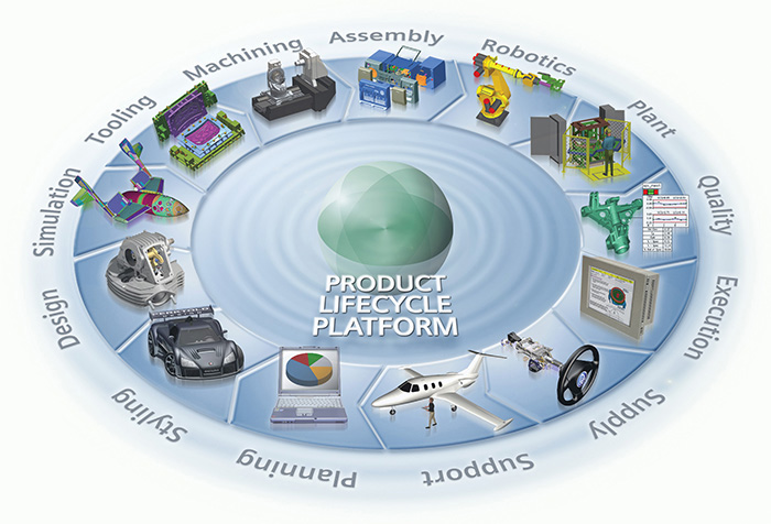
15.6 Enterprise-wide Product Data Management. The Siemens PLM System is designed to serve data inside and outside the organization. This illustration shows types of information centered around a 3D design database available to designers, marketing, manufacturing, engineering, procurement, service and support team members, as well as to external team members, such as multinational manufacturing suppliers and contractors. Data from the database would be provided to external users over the Internet (for public data) or via a secure, password-protected site (to share nonpublic information with suppliers and other partners in remote locations). (©2016 Siemens Product Lifecycle Management System. Reprinted with permission.)
Organized by Product
The PDM system attempts to manage all the product-related information—specifications, part information, NC programs, CAD drawings, models, spreadsheets, test results, electronic images, and paper documents—throughout the life cycle of the product. This information includes release to manufacturing forms, change orders, and approval documentation. Traditional approaches to recording and preserving part and assembly files do not capture other pieces of data related to the project, or they capture it in a way that is difficult to obtain. For example, the weight of a component may be derived from the model file document in the system but not stored separately where it could be retrieved as an attribute of that component. Product data management systems allow users to store documents—be they CAD files, spreadsheets, or memos—as well as attribute data about a product.
The product in PDM relates to how the information is organized. A database, like your file system, can be organized in many ways. The information managed by a PDM system has traditionally been stored by functional area: manufacturing has the programs used to control the manufacturing machinery, marketing has the written specifications for the final product, and purchasing may have the final bill of materials. To obtain one of these pieces of information, the user needs to know how it is stored and by whom. Each may be stored in a different database. A PDM system uses the product as the organizing principle. To find a piece of information, the user can start with the product to which it relates.
A Relational Database
All data management systems use some type of database to store the data they control. Because product data management systems are organized around a product, they generally use a relational database to allow the system to serve information in many different ways.
Some data management systems use a simpler kind of database to organize data, often referred to as flat files. Flat-file databases are analogous to a filing cabinet. Each record is like a card in the cabinet. If each record is a document, then the attributes of the document can be stored as searchable fields on the card. For example, a CAD file might have fields for the project name, the type of part, material, the designer, revision, change order number, and so on. Any data field can be used to search the database. The database is called a flat file because it is like a stack of cards, as shown in Figure 15.7.

15.7 The structure of a flat file is like an index card. The top-level structure—the document—is the card, and any data pertaining to the document are fields on the card. If the top level of the database were a project, then the fields associated with it would be the individual documents that relate to the project.
A drawback of a flat-file database is the difficulty of showing multiple relationships. A drawing of a standard part, for example, should be stored only once in the database, although it is a part that appears in many different projects. If the project name for a part is a single field, with which project should the standard part be associated? If more fields are added to accommodate multiple project names, each of these fields will have to be searched anytime the user wants to find a list of parts by project.
A relational database overcomes this limitation by breaking data into tables of data that are related to each other through a common field. Figure 15.8 shows how data might be organized in a relational database. A client table could assign a unique client ID to each client and contain fields for all the information about a client. A project table would assign a unique project ID to every project and include other fields of information related to the project, such as the client ID. Both tables share the client ID field, making it possible to link the data between the two tables. This allows a user to search any table of data and retrieve information from related tables through the common link.

15.8 Each entity in a relational database is stored in a table and linked to other entities by the fields they have in common.
Relational capabilities make it possible to search for and view data in the system in many different ways. Each document in the system is stored in one location, but it can belong to several different groups of documents at the same time through the relationships defined in the database. A table of standard parts, for example, could be linked by ID number to any number of projects yet reside in the database in a single location.
The relational capability makes it possible to query the system in a variety of ways. A product-based structure, for example, relates every document to a product manufactured by the company. Documents can be stored in separate tables by document type, such as drawing, 3D model, technical publication, or spreadsheet file. Each kind of file can be stored with attributes relevant to its type, such as title block information for a drawing, or publication date for a technical manual. The relations in the database make it possible to search for data in almost any combination (Figure 15.9). A user could locate, for example, all the sheet metal parts fabricated by a particular vendor for a particular customer, or all stainless steel fasteners less than 10 mm long.

15.9 Search features like those in Siemens Teamcenter PLM let users search to quickly find and view CAD files as well as other project information. (©2016 Siemens Product Lifecycle Management System. Reprinted with permission.)
15.11 Managing Work Flow
Storage and retrieval of data is the key aspect of a product data management system, but its contribution to concurrent engineering is its ability to control access to and ensure accuracy of shared data. Work flow is the term used to describe how information moves through the system’s checkpoints and out and back to team members.
The key to any electronic document control system is that a master record of all product data is stored securely on a networked computer system. The system provides access to the documents according to the user’s defined level of permission. To work with a document, a user must check it out, as one would check out a book from a library. Changes that are made to the electronic file must be approved before the document is returned to the system. The earlier version of the document is stored as it appeared before the revision in order to provide a design history.
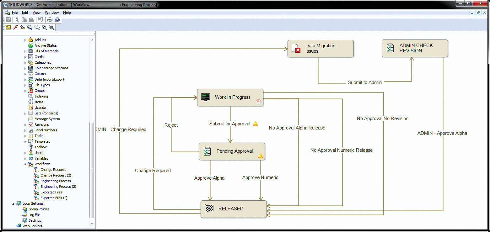
Most PDM systems allow for sophisticated levels of access that fit the organization and how they work. Only certain individuals will have the authority to create or change documents for a particular project. In a concurrent environment, the checkpoints corresponding to drawing approval may not be enough. Coding drawings according to their status—submitted, checked, approved, released—may offer more flexibility in how files are shared (Figure 15.10).
Many PDM systems also provide for tools that allow input from members who do not have permission to change a model but may “redline” a document (mark possible changes that are flagged and that can be implemented if they are approved by someone with permission to change the file) or add “sticky notes” that can be reviewed by the file’s owner and other team members. This capability can improve team communication and interaction without adding meeting time or paperwork.
Archiving Work History
The controls built into work-flow systems in the product data management system function similarly when data are to be archived for long-term storage. PDM systems generally offer more information about the project history than a simple archive of files would. The system might capture time spent in each phase of the project, the number of revisions made at each stage, a list of team members who were involved, and other information that may be used to measure and improve productivity.
The system can also expand the snapshot in time that an engineering drawing represents. At any given point in time, the system can produce not just the drawing or CAD model but also a complete set of data for a project at that moment in time. This kind of archive can make it possible to backtrack to a problem point in the design or revisit a key decision point and pursue an alternative line with the design from that point.
Individual Productivity
One of the benefits that companies expect from an enterprise-wide product data management system is improved productivity that translates to reduced time-to-market for their products. Rockwell Corporation reported that implementing a PDM system reduced the time it took its project managers to cost a product from 4 to 5 days, to 4 to 5 minutes because all the data were easily available. Similarly, design engineers can spend up to 25% to 30% of their time looking for information, retrieving information, waiting for copies of drawings, and archiving new data. An effective PDM system can eliminate this unproductive time because the designer knows where and how to look for released designs and other data. By providing easier access, the system can also promote reuse of existing designs and reduce the time spent “reinventing the wheel.”
Many of the issues of file management can also be automated or aided by PDM software. By establishing work groups in the system that are linked to projects, the system can be designed to notify members of the group whenever a file is updated or changed. Designers who have downloaded copies of files can work with them until notified that they need to download a later version. Other PDM and file management systems, especially those implemented over distance networks, seek to reduce download times by comparing file dates and versions on the server and the receiving machine. For any set of files, the system will download only those that are more current than those already available. Graphical preview capabilities built into many systems also make it easier to identify files, especially large CAD files, before downloading them.
Instant-messaging tools, project e-mail grouped around thematic threads that team members can read and review as needed, automated file management tools, file transfer routines, and data query tools all help capture and disseminate data with the least amount of effort on the part of the user.
15.12 Data Management and the Web
Implementing a product data management system, or even a simpler document database, is a significant investment in capturing information, defining the use of various documents, and specifying the hardware and software needed. For smaller companies, the investment in a full-blown PDM system may not be necessary, but the strategy of organizing and retrieving engineering design data is still applicable.
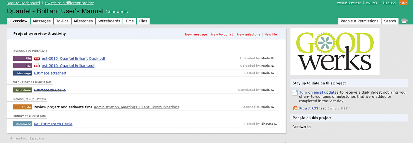
Smaller companies, or those that must interact regularly with suppliers and partners in distant locations, can use the Internet to distribute access to project data. By creating a secure website, a company can provide network users access to the project data. Many of the same messaging and document management functions provided by a PDM system can be provided through browser and Internet-based tools (Figure 15.11).
Database servers that automate product websites also can provide access to the most current information and files. In addition, the Web has spawned a full range of tools for previewing graphical information that can be used to navigate through and select from CAD information.
CAD Files on the Web
One of the most useful developments for publishing CAD data on the Web is a viewer. A viewer is a small application that allows you to open and view CAD drawings without having the application package itself. Most CAD platforms offer a viewer that allows you to zoom, pan, and print the model. Without the cost of printing or mailing, a viewer makes it possible to make your CAD data viewable to a wider audience—including customers and nonengineers who want to preview a design but may not be able to interpret a 2D drawing.
The graphical nature of the Web and the rapid pace at which tools are being developed for it make it an ideal environment for sharing data among team members and for publishing CAD data. By preserving the interactivity of the model and the complexity of the data, yet making the model available to individuals who do not have a CAD workstation on their desktop, Web viewers overcome many of the limitations of paper drawings for those not familiar with technical drawings.
Industry Case: Engineering Documentation: Make It Withstand the Test of Time
“People often don’t understand why there are such strict requirements for engineering documentation within the company,” says Cliff Moore, Engineering Document Control Manager at Delta Design, the largest manufacturer of semiconductor test-handling equipment used by IC manufacturers around the world.
Delta Design is an ISO 9000–compliant company that uses a worldwide network of suppliers and has manufacturing and assembly facilities in the United States, the Philippines, Mexico, Singapore, and China. However, ISO guidelines do not tell a company how to manage and control its documents. Each company must have its own system that assures the quality of the product. Proper engineering documentation is one important aspect of this overall system.
At Delta Design, engineers use SolidWorks software to create 3D part models and assemblies. Drawings are created from the models to provide detailed manufacturing information. One aspect of Cliff’s job is to manage the release and storage of the database of drawings and models.
New projects often start with a concept from the technical sales force or from an existing customer. From the concept, design specifications are written to guide the development of the new machine or subsystem. After the initial design specification is approved, engineers work freely on concepts and models, storing them on areas of the network devoted to their work group. As the design develops, new part identifying numbers may be tracked using an engineering revision code that Delta Design calls an X-rev. Once the design has been refined, tested, prototyped, and retested for fatigue and other long-term failure issues, and cost analysis performed, successful designs move on to the engineering release process. This is where Cliff and his team get involved.
To receive the necessary approvals to release the design, the engineer provides 3D models for each designed-for-manufacture part, an assembly model, and a set of drawings. An assembly drawing lists the bill of materials (BOM), which identifies each item and its part number (also in the title block of the part drawing) and illustrates how the device assembles. Separate work instructions may need to be included for complicated processes. Off-the-shelf purchased parts, such as connectors, washers, and screws, are also assigned part numbers and cross referenced with the manufacturer part number. In most cases the suppliers or manufacturers have solid models that can be downloaded, but if not, the engineer creates those models as needed. Test results and engineering notes are also a part of the release package.
The files for the project are then copied to a temporary directory, where they are reviewed by the individuals who will approve the release for manufacturing. The files in the temporary directory can be read by anyone but only changed or moved by a document control technician. The engineer completes an ECO requesting approval to release the new parts and assembly (see Figure 15.12). Cliff reviews the drawing package to ensure “due diligence” on the part of the designer. Cliff reminds them, “Someone may need to come back to this information five or ten years later, long after the ‘tribal knowledge’ about the project is gone.”

15.12 Delta Design’s digital ECO form is used to release new parts or to approve changes to existing parts.
Even though the approval process is digital, a face-to-face meeting is also held to review all new part releases and revisions to existing parts. This ensures good communication among all the different departments involved. Members from manufacturing, purchasing, product management, various engineering disciplines, and document control must give their final approval. Once everyone has signed off, the parts are ready for release and get the go-ahead for manufacture.
At this point, Cliff moves the part and assembly files into the master file storage area for released parts. Each file is named with its part number. Delta Design makes complex automated equipment for semiconductor test handling. They have tens of thousands of released parts. To make retrieval quicker, the files are stored in separate directories for assembly models, part models, and drawing files. Subfolders group the parts using the first few digits of the part number (Figure 15.13). Cliff and his staff verify that the links to parts within the assembly are working by opening the files after they are moved to the master directory. The same part may be used in many different assemblies and subassemblies. Opening each assembly file after it is moved ensures that all the correct part files are available and that the paths to them within the assembly are correct.
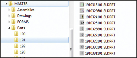
15.13 Released part models are stored in a master directory where they can be read but not erased or changed by anyone except document control personnel.
The other side of the equation is the Enterprise Resource Planning (ERP) software that the company uses. Information about parts, such as number, cost, purchasing agent responsibility, number on hand, reordering quantities, and where the part is used, is stored in a large database. PDFs of the part drawings are linked to the part information in the database. Anyone needing the information can search the database and view the linked part drawings.
Soon, Cliff hopes to move to an enterprise-wide PDM system that provides integrated work-flow tools, model checkout management, and automated notifications. Delta Design currently uses its own “homegrown” tools for these, which may require checking in several different places to ensure that two different project teams do not work on designs that change the same model. Cliff currently keeps a spreadsheet of all the ongoing projects and the part numbers that are involved. He looks forward to being even more efficient when these steps are automated.
(Case study images courtesy of Delta Design, a Cohu Company.)
Engineering Change Order (ECO)
International Organization for Standardization (ISO)
Chapter Summary
• Models and drawings are detailed and expensive to create. It is important to understand how to manage product data for maximum advantage.
• Engineering documents have requirements for control and long term storage.
• Drawings, documented models, and other design data play an important function in engineering documentation.
• Some basic steps are typical for approving and controlling CAD data. You should also be able to describe various systems for producing engineering drawing numbers.
• Good file-handling and backup procedures require organization and a systematic approach.
• Terminology related to engineering documentation includes some commonly used acronyms such as PDM, ECN, and ECO and you should be familiar with the use of these terms.
Skills Summary
You should understand issues in managing engineering drawings and product data. The exercises presented here allow you to describe how engineering documents are controlled and the role of drawings and CAD data in engineering documentation. You should be able to list the basic steps in approving and controlling CAD data and to describe various systems for producing engineering drawing numbers. Good file-handling and backup procedures require organization and a systematic approach. You should be able to describe how to use folders to organize files and directories in a consistent manner. You should be familiar with terminology related to engineering documentation and be able to define commonly used acronyms.
Review Questions
1. How can CAD files be cataloged for future use?
2. List at least three ways in which you can use the Internet to communicate to other people involved in the product development or design process.
3. What is an ECO? What approval steps might be associated with it in a CAD drawing?
4. How can an engineer or designer determine whether a drawing is the most up-to-date when they are reviewing it on a printed sheet?
5. What is the role of a PDM system?
Chapter Exercises
Exercise 15.1 Develop a file naming convention and directory structure that would work for the documents related to your course work. Consider all the courses you are likely to take over your college years and how you might want to access documents from them. What different kinds of documents would you want to include? Anticipate making the documents available over a network to your prospective employer, and create a naming structure that will convey meaningful information about the document file. Draw a flowchart of the directory structure you would use to organize the files. Show the steps needed to access a particular type of document.
Exercise 15.2 A three-person company designs, fabricates, and sells a line of biological laboratory equipment. All drawings are produced using a CAD system. The company sells products to about twelve labs, with each user needing small custom features on the base product line. Contrast this company’s document control needs with that of a large company that must keep track of multiple part source vendors, and uses dispersed teams of designers. What are the differences and similarities between the drawing control requirements of the two companies?
Exercise 15.3 Why might you wish to store electronic files in a directory different from the one containing your application software?
Exercise 15.4 Provide the source words and a one- or two-sentence definition of the following common engineering and computer acronyms (some research or investigation may be required):
PDM |
FEA |
ISO |
ECO |
ECN |
VRML |
CAD |
EDMS |
WORM |
ASTM |
HTML |
.DXF |
Exercise 15.5 What is the key to a successful product data management system?
Exercise 15.6 It is common to begin a project with a drawing tree or drawing breakdown structure (DBS) to identify the relationships among detail components, subassemblies, and assemblies. Create a DBS for a simple device, such as a stapler, doorknob, or vise.

Exercise 15.7 A block diagram of drawing release process steps for a conventional paper drawing has been started for you on the right. Complete this flowchart and then create a block diagram of typical steps in the drawing release process for a computerized part in a digital database.
Exercise 15.8 A designer creates two original mating part drawings on a CAD system and stores them digitally in a specific folder on her PC. The drawings are printed and the prints are issued to the machine shop to guide part fabrication. After about 100 parts of the expected 300-part run have been produced, a change is requested by the shop to permit a larger bolt size to be used for assembly. The bolt size request affects both mating parts, so that interchangeability between the old and new parts will be lost. The designer complies and issues new drawings.
a. How should these new drawings be stored? Distributed? Labeled?
b. What procedure would you recommend to identify both drawings and parts produced?
c. Can you anticipate problems that might arise if good practices are not followed?

Exercise 15.9 ISO 9000 requirements for document and quality control are listed in a 12-item checklist in this chapter. State the logical reason for each of these 12 items, including potential consequences of ignoring each of the recommendations.
Exercise 15.10 Visit the company website for your CAD package and download the viewer software (if available). What types of files can the viewer open? What viewing and annotation options are built into the viewer?