
34
CHAPTER
Advanced Communications Systems
THE TERM WIRELESS AROSE IN THE EARLY 1900S WHEN INVENTORS AND EXPERIMENTERS BEGAN sending and receiving messages using EM fields. Before long, wireless acquired more specific terminology, such as radio, television, and EM communications. In the 1980s and 1990s, the term wireless emerged again, this time in the consumer context.
Cellular Communications
Wireless telephone sets operate in a specialized communications system called cellular. Originally, the cellular communications network served mainly traveling business people. Nowadays, many (if not most) ordinary folks regard cell phones as necessities, and most cell-phone sets have non-voice features, such as text messaging, Web browsing, video displays, and digital cameras.
How Cellular Systems Work
A cell phone looks like a hybrid between a cordless telephone receiver and a walkie-talkie, but smaller. Some cell phones have dimensions so tiny that an unsuspecting person might mistake them for packs of chewing gum or candy. A cell-phone unit contains a radio transmitter and receiver combination called a transceiver. Transmission and reception take place on different frequencies, so you can talk and listen at the same time, and easily interrupt the other party if necessary, a communications capability known as full duplex.
In an ideal cellular network, every phone set constantly lies within range of at least one base station (also called a repeater), which picks up transmissions from the portable units and retransmits the signals to the telephone network, to the Internet, and to other portable units. A so-called cell encompasses the region of coverage for any particular repeater.
When a cell phone operates in motion, say, while the user sits in a car or on a boat, the set can move around in the network, as shown in Fig. 34-1. The dashed curve represents a hypothetical vehicle path. Base stations (dots) transfer access to the cell phone among themselves, a process called handoff. The hexagons show the limits of the transmission/reception range (or cell) for each base station. All the base stations are thereby connected to the regional telephone system, making it possible for the user of any portable unit to place calls to, or receive calls from, anyone else in the system, whether those other subscribers have cell phones or old-fashioned landline phones.
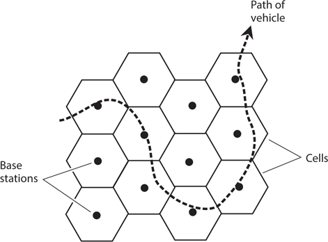
34-1 In an ideal cellular system, a moving cell-phone set (dashed line) always remains within range of at least one base station.
Cellular connections sometimes suffer from frequency call loss or breakup when signals transfer from one repeater to another. A technology called code-division multiple access (CDMA) reduces the frequency and severity of this problem compared to the early years of cellular technology. In CDMA, the repeater coverage zones overlap significantly, but signals don’t interfere with each other because every phone set possesses a unique signal code. Rather than abruptly switching from one base-station zone to the next, the signal goes through a region in which it flows through more than one base station at a time. This make-before-break scheme helps to mitigate, but not eliminate, one of the most annoying problems inherent in cellular communication.
Caveats and Cautions
Unfortunately, call loss and breakup can occur even in a well-designed and constructed network when a user makes or receives calls from a physical location that suffers from poor reception. In a digital communications system, signals don’t fade in and out as they do with analog radios. Instead, the signals tend to appear and disappear completely, sometimes off-again and on-again in a maddening flurry. Who among us has not experienced this phenomenon while using a cell phone? In some cities, one often sees shattered cell-phone sets lying in gutters or parking lots—victims of chucking, in which a furious user has hurled a phone set to the pavement with major-league-baseball speed. (I do not recommend nor condone this practice.)
In order to use a cellular network, you must purchase or rent a phone set and pay a monthly fee, or else buy time in advance. When using the system, you must never forget that your communications are not necessarily private. In this age of personal-security concerns and corporate espionage, you had better assume that every word you say, every character you type, every photograph you take, and every video you capture can be intercepted by anyone in the world. It’s easier for unauthorized people to eavesdrop on wireless communications than to intercept wire or cable communications, and such people have no scruples about posting “hacked” conversations, texts, pictures, or videos on the Internet.
Cell Phones and Computers
You can connect a personal computer (PC) to an older cell-phone set (one that doesn’t have Internet access built-in) with a portable modem that converts incoming computer data from analog to digital form, and also converts outgoing data from digital to analog form. In this way, you can access the Internet from anywhere within range of a cellular base station, and have all the power of your home computer’s Web browser at your disposal. Figure 34-2 is a block diagram of this scheme.

34-2 You can equip a cell phone with a modem (if it doesn’t already have a modem built-in), allowing portable or mobile access to online networks with the full power of your personal computer.
In recent years, high-end cell-phone sets have become available with modems built-in, but they generally have less sophisticated Web browsers than personal computers do.
Most commercial aircraft have telephones at each row of seats, along with jacks into which you can plug a modem or portable computer. If you plan to access the Internet from an aircraft, you must generally use the phones provided by the airline, not your own cell phone because radio transceivers can cause interference with flight instruments. You must also observe the airline’s restrictions concerning the operation of electronic equipment while in flight.
Satellites and Networks
A satellite communications system resembles a huge cellular network with the repeaters in space rather than on the earth’s surface. The zones of coverage are large, and they constantly change in size and shape if the satellite moves relative to the earth’s surface.
Geostationary-Orbit Satellites
Geostationary satellites serve important roles in television (TV) broadcasting, telephone and data communication, weather and environmental data-gathering, radiolocation, and radionavigation.
In geostationary satellite networks, earth-based stations can communicate through a single “bird” only when the stations both lie on a line of sight with the satellite. If two stations are nearly on opposite sides of the planet, say, in Australia and Wisconsin, they must operate through two satellites to obtain a link (Fig. 34-3). In this situation, signals are relayed between the two satellites, as well as between either satellite and its respective earth-based station.

34-3 A communications link involving two geostationary satellites.
A potential problem with geostationary satellite links results from the fact that the signal must follow such a long path that perceptible propagation delays occur. Engineers call this delay, and its observed effects, latency. The delay doesn’t cause much trouble with casual communications or Web browsing, but it slows things down when computers are linked to combine their processing power. It also makes high-end, Internet-based computer-game playing between two or more users difficult or impossible because one user can’t quickly respond to the others’ moves in fast-paced action scenes.
Low-Earth-Orbit Satellites
The earliest communications satellites orbited only a few hundred kilometers above the earth. They were low-earth-orbit (LEO) satellites. Because of their low-altitude orbits, LEO satellites took only about 90 minutes to complete one revolution. Communication was intermittent at best, because a satellite remained within range of any given ground station for only a few minutes at a time. This limitation was the main reason why geostationary satellites became predominant once rocket technology progressed to the point at which satellites could reach the necessary altitude and acquire the necessary orbital precision.
Despite their advantages, geostationary satellites have certain limitations. A geostationary orbit requires constant adjustment because a tiny change in altitude will cause the satellite to get out of sync with the earth’s rotation. Geostationary satellites are expensive to launch and maintain. When communicating through them, significant latency exists because of the path’s length. Reliable communications demand fairly high transmitter RF output power, and a sophisticated, precisely aimed antenna, usually a helix or dish. These problems with geostationary satellites have brought about a revival of the LEO paradigm. Instead of one single satellite, the new concept dictates a large fleet of them, in effect building a “cellular network in reverse.”
In a well-designed and well-implemented LEO-satellite system, at least one satellite always lies in direct line-of-sight range for every user on earth. The satellites can relay messages throughout the fleet. Therefore, any two points on the surface can always make, and maintain, contact through the satellites. The satellites follow polar orbits (routes that pass over or near the earth’s geographic poles) to optimize the geographical coverage. Even if you work in the Arctic or Antarctic, you can use a LEO-satellite system. This flexibility does not hold true with geostationary satellite networks, where the regions immediately around the geographic poles remain invisible to the satellites.
A LEO-satellite communications link is easier to access and use than a geostationary-satellite link. A small, simple, non-direction antenna will suffice; you don’t have to aim it in any particular direction. The transmitter can reach the network using only a few watts of RF output power. The latency rarely exceeds 100 milliseconds (ms), compared with as much as 400 ms for geostationary-satellite links.
Medium-Earth-Orbit Satellites
Some satellites revolve in orbits higher than those normally considered low-earth, but at altitudes lower than the geostationary level of 35,800 km (22,200 mi). These intermediate “birds” are called medium-earth-orbit (MEO) satellites. A MEO satellite takes several hours to complete each orbit. MEO satellites operate in fleets, in a manner similar to the way LEO satellites are deployed. Because the average MEO altitude exceeds the average LEO altitude, each MEO “bird” can cover a larger region on the surface at any given time. A fleet of MEO satellites can be smaller than a comparable fleet of LEO satellites, and still provide continuous, worldwide communications.
The orbits of geostationary satellites are essentially perfect circles, and most LEO satellites orbit in near-perfect circles as well. But MEO satellites often have elongated, or elliptical, orbits. We call the point of lowest altitude the perigee and the point of greatest altitude the apogee. They can differ considerably. The MEO satellite orbits at a speed that depends on its altitude. The lower the altitude, the faster the satellite moves. A satellite with an elliptical orbit crosses the sky rapidly when it “swoops low” near perigee, and slowly when it “flies high” near apogee. Users find it easiest to use an MEO satellite when its apogee is high above the horizon, as seen from the earth surface; under these conditions, the “bird” stays in the visible sky for a long time.
Every time a MEO satellite completes one orbit, the earth rotates beneath it. The rotation of the earth rarely coincides with the orbital period of the satellite. Therefore, successive apogees for a MEO satellite occur over different points on the earth’s surface. This so-called apogee drift complicates satellite tracking, necessitating computers programmed with accurate orbital data. For a MEO system to effectively provide worldwide coverage without localized periodic blackouts, the various satellites must follow diverse yet coordinated orbits. In addition, the network must have enough satellites so that each point on the earth always lies on a line of sight with one or more of them. Ideally, every user should always observe at least one in-sight “bird” near its apogee.
Wireless Local-Area Networks
A local-area network (LAN) comprises a group of computers linked together within a building, campus, or other small region. The interconnections in early LANs were made with wire cables, but wireless links have become standard today. A wireless LAN offers flexibility because the computer users can move around without having to bother with plugging and unplugging cables. This arrangement works especially well when most, or all, of the users have portable computers. The geometric arrangement of major system components is called the LAN topology. Two major wireless LAN arrangements dominate: the client-server topology and the peer-to-peer topology.
A client-server wireless LAN (Fig. 34-4A) has one large, powerful, central computer called a file server, to which all the smaller personal computers are linked. The file server has enormous computing power, high speed, and large storage capacity. It can contain all the data for every user. End users do not communicate directly. All the data must pass through the file server.

34-4 At A, a client-server wireless LAN. At B, a peer-to-peer wireless LAN.
In a peer-to-peer wireless LAN (Fig. 34-4B), all of the computers have more or less equal computing power, speed, and storage capacity. Each user maintains his or her own data. Subscribers can communicate directly without the data having to pass through any intermediary. This mode offers greater privacy and individuality than the client-server topology, but it tends to slow down when many users need to share data all at once.
Large institutions favor client-server LANs, while small businesses and schools, or departments within a larger corporation or university, prefer cheaper and more user-friendly peer-to-peer LANs. In the illustrations of Fig. 34-4, only three personal computers are shown in each network. However, any LAN can have as few as two, or as many as several dozen, computers.
Home Internet users sometimes employ a modified version of the arrangement shown in Fig. 34-4A. In place of the file server, a device called a wireless router provides a hub through which the computers can communicate. The router connects to the Internet through a high-speed interface such as a cable modem, allowing several computers in a household to have Internet access at the same time.
Amateur and Shortwave Radio
In most countries of the world, people can obtain government-issued licenses to send and receive messages by radio for nonprofessional purposes. Americans call this hobby amateur radio, or ham radio. If you want only to listen to communications and broadcasting, and not to transmit signals, you do not need a license in the United States (although you do need one in some countries).
Who Uses Amateur Radio?
Anyone can use ham radio provided they can pass the tests necessary to obtain a license. Amateur radio operators (or “hams”) communicate in diverse modes including voice, Morse code, television, and various forms of digital text messaging. Text messaging can be done in real time, or by posting short passages similar to electronic mail (e-mail). Radio amateurs have set up their own radio networks to take advantage of a mode known as packet communications, or packet radio. Most packet networks these days have Internet gateways, but a few amateur radio operators store digital information at their stations, in effect creating a “virtual Internet” independent of the conventional communications infrastructure.
Some radio “hams” chat about anything they can think of (except business matters, which are illegal to discuss using amateur radio). Others like to practice emergency communications skills so that they can serve the public need during crises, such as hurricanes, earthquakes, or floods. Still others like to go out into the wilderness and talk to people far away while sitting out under the stars and using battery power. Amateur radio operators often communicate from cars, boats, aircraft, and bicycles; this mode is called mobile operation. When transceivers are used while walking or hiking, the mode is known as portable, or handheld operation.
Amateur Equipment and Licensing
A simple amateur radio station has a transceiver (transmitter/receiver), a microphone, and an antenna. A small station can fit on a desktop, and has physical size and mass comparable to a component type hi-fi stereo system. The operator can add station accessories until the “rig” becomes a large installation, comparable to a small commercial broadcast station.
Figure 34-5 is a block diagram of a fixed amateur radio station. The computer can control the functions of the transceivers, and can also facilitate digital communications with other radio amateurs who own computers. The station can be equipped to interface with the telephone services, also called landline. The computer can control the antennas for the station, and can keep a log of all stations that have been contacted.

34-5 A computer-controlled amateur radio station.
You can learn all about amateur radio as practiced in the United States by contacting the headquarters of the American Radio Relay League (ARRL), 225 Main Street, Newington, CT 06111. They maintain a Web site at www.arrl.org. If you live outside the United States, the ARRL can direct you to an organization in your home country that can help you obtain a license and “get on the air.”
Shortwave Listening
The high-frequency (HF) portion of the radio spectrum, at frequencies between 3 and 30 MHz, is sometimes called the shortwave band. This term constitutes a misnomer by contemporary and technical standards. The wavelengths greatly exceed those of EM fields at ultra high frequencies (UHF), microwaves, and infrared (IR), at which wireless devices commonly operate these days. In free space, a frequency of 3 MHz corresponds to a wavelength of 100 m, while a frequency of 30 MHz corresponds to a wavelength of 10 m. Around the year 1920 when the shortwave band got its name, the wavelengths between 100 m and 10 m were indeed short in relative terms; most broadcast and communications signals had wavelengths in the multi-kilometer range!
Anyone can build or obtain a shortwave or general-coverage radio receiver, install a modest outdoor antenna, and listen to signals from all around the world. This hobby is called shortwave listening, or SWLing. In the United States, the proliferation of computers and on-line communications has, to some extent, overshadowed SWLing. These days, most young people grow up ignorant of shortwave broadcasting and communications, although this mode still predominates in much of the world. Nevertheless, some folks find never-ending fascination in the fact that people can contact each other using “old-fashioned radios” over vast distances using wireless devices alone, without the need for any human-made infrastructure other than an antenna at the source and another antenna at the destination. The ionosphere returns shortwave signals to the earth’s surface, allowing reliable global broadcasting and communication to take place today, exactly as it has since the first days of radio during the early 1900s.
You can find commercially manufactured shortwave receivers if the prospect of SWLing interests you. Some electronics stores carry one or more models, along with antenna equipment, for a complete installation. Amateur-radio conventions, also called “hamfests,” can serve as sources of shortwave receiving equipment at bargain prices. For information about events of this sort in your area, you can contact the American Radio Relay League at www.arrl.org, or visit your local amateur radio club.
Security and Privacy
In recent years, people have grown increasingly concerned about the security and privacy of electronic communications, particularly wireless. When a wireless system is compromised, even the most expert engineers might not detect the intrusion until the system or its subscribers have suffered irreparable harm. In some cases, the intrusion escapes detection altogether, and the victims never find out why strange and recurrent personal security problems continue to plague them.
Wireless versus Wired
Wireless eavesdropping differs from conventional wiretapping in two fundamental ways. First, eavesdropping is easier to do in wireless systems than in hard-wired systems. “Antique” hard-wired phone sets might seem inconvenient, but when you use them, your privacy will generally remain more secure than it will if you use a wireless device. Second, eavesdropping of a wireless link can be carried out secretly, but a good engineer can usually detect and locate a leak or tap in a hard-wired system.
If you use wireless devices to perform any part of a communications link, then a spy can place an eavesdropping receiver within range of your transmitting antenna (Fig. 34-6) and intercept your transmissions. The existence of a wireless tap has no effect on the electronic characteristics of any equipment in your system. A wary engineer might detect the presence of the eavesdropping receiver by noticing the spurious output caused by its IF oscillators, but in today’s “RF-saturated” world, the presence of “one more signal” makes virtually no difference in the EM environment.

34-6 Eavesdropping on RF links in a telephone system. Heavy, straight lines represent wires or cables; zig-zag lines represent RF signals.
Levels of Security
We can categorize telecommunications security in terms of four levels, ranging from 0 (no security) to 3 (the most secure connections technology allows).
No Security (Level 0) In a communications system with level 0 security, anyone can eavesdrop on a connection at any time, as long as they’re willing to spend the money and time to obtain the necessary equipment. Two examples of level 0 links are amateur radio and Citizens’ Band (CB) voice communications.
Wire-equivalent Security (Level 1) An end-to-end hard-wired connection requires considerable effort to tap, and sensitive detection apparatus can usually reveal the existence of a wiretap. A communications system with level-1 security must have certain characteristics for optimum effectiveness:
• The cost must stay affordable
• The system must be reasonably safe for personal financial transactions
• When network usage is heavy, the degree of privacy afforded to each subscriber should not decrease, relative to the case when network usage is light
• Ciphers, if used, should remain unbreakable for at least 12 months, and preferably for 24 months or more
• Encryption (“secret-cipher”) technology, if used, should be updated at least once every month
Security for Commercial Transactions (Level 2) Some financial and business data demand protection beyond the wire-equivalent level. Some companies and individuals refuse to transfer money by electronic means because they fear criminals will gain access to an account. In a communications system with level-2 security, the encryption used in commercial transactions should be sufficiently strong so that a potential intruder (also called a hacker) would need at least 10 years, and preferably 20 years or more, to break the cipher. Users should update the technology at least once a year.
Military Level Security (Level 3) Security to military specifications (also called mil spec) involves the most sophisticated encryption available. Technologically advanced countries, and entities with economic power, have an advantage here. However, as technology gains ever more (and arguably too much) power and influence over human activities, aggressor nations and terrorists might injure powerful nations by seeking out, and striking at, the weak points in communications infrastructures. In a communications system with level-3 security, the encryption scheme should be such that engineers believe it would take a hacker at least 20 years, and preferably 40 years or more, to break the cipher. The technology should be updated as often as economics allow.
Extent of Encryption
In a wireless system, we can achieve reasonable security and privacy with digital encryption that renders signals readable only to receivers with the necessary decryption key. This practice makes it difficult for unauthorized people to access or disrupt the system. The best decryption keys are complicated and obscure, making it hard (hopefully impossible) for hackers to figure it out.
For level-1 security, encryption is required only for the wireless portion(s) of the circuit. We should change the cipher at regular intervals to keep it “fresh.” The block diagram of Fig. 34-7A shows wireless-only encryption for a hypothetical cellular telephone connection.
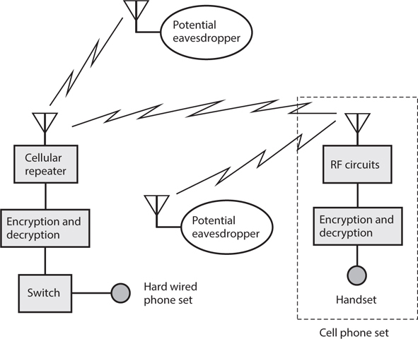
34-7A Wireless-only encryption. Heavy, straight lines represent wires or cables; zig-zag lines represent RF signals.
If we want to attain level-2 or level-3 security, we must use end-to-end encryption, in which we encrypt the signal at all intermediate points, even those parts of the link for which the signals propagate by wire or cable. Figure 34-7B shows this scheme for a hypothetical cellular connection.
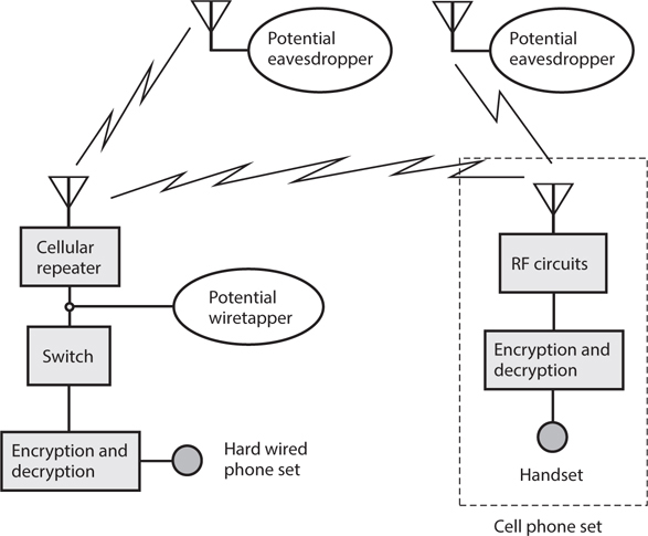
34-7B End-to-end encryption. Heavy, straight lines represent wires or cables; zig-zag lines represent RF signals.
Security with Cordless Phones
Most cordless phones are designed to make it difficult for unauthorized people to “hijack” a telephone line. Prevention of eavesdropping enjoys a lower level of priority, except in expensive cordless systems. If you have any concerns about using a cordless phone in a particular situation, use a hard-wired phone set instead.
If someone knows the frequencies at which a cordless handset and base unit operate, and if that person wants to eavesdrop on conversations that take place using that system, then that individual can place a wireless tap on the line. The intruder can intercept your conversations from a point near your cordless phone set and its base unit, transmit the data to a remote site (Fig. 34-8), and record it there.

34-8 Wireless tapping of a cordless telephone.
Security with Cell Phones
In effect, cellular telephones function as long-range cordless phone sets. The wider coverage of cellular repeaters, as compared with cordless base units, increases the risk of eavesdropping and unauthorized use. A few cell phone vendors advertise their systems as “hacker-proof.” Some of these claims have more merit than others. Anyone with engineering experience ought to regard the word “proof” (meaning “immune”) with skepticism. Digital encryption constitutes the most effective way to maintain privacy and security of cellular communications. Nothing short of strong digital encryption can offer any hope of keeping out a determined hacker.
Access and privacy codes, as well as data, must undergo strong digital encryption if a cell-phone system is to attain an optimum level of security. If an unauthorized person knows the code with which a cell phone set accesses the system (the “name” of the set), the hacker can program one or more rogue cell phone sets to fool the system into “thinking” that those sets belong to the user of the authorized set. This practice is known as cell phone cloning.
In addition to digital encryption of data, user identification (user ID) must be employed. The simplest form of user ID is a personal identification number (PIN). More sophisticated systems can employ voice-pattern recognition, in which the phone set functions only when the designated user’s voice speaks into it. Hand-print recognition, electronic fingerprinting, or iris-pattern recognition—which, along with voice-pattern recognition, constitute examples of biometric security measures—can further protect against malicious eavesdroppers or hackers.
Modulated Light
Electromagnetic energy of any frequency can undergo modulation for the purpose of transmitting information. Modulated light has recently become a significant means of conveying data, although the concept has existed for more than a century.
A Simple Transmitter
Figure 34-9 illustrates the components of a simple modulated-light voice transmitter that you can build for a few dollars using parts available from electronics supply stores. This circuit uses a microphone, an audio amplifier, a transformer, a current-limiting resistor, an LED, and a source of DC power such as a battery. Some hobby electronics stores sell complete audio amplifier modules. Alternatively, you can construct a simple audio amplifier circuit using a rugged bipolar transistor or operational amplifier (“op amp”) chip. Ideally, the module or amplifier should have a built-in gain control.

34-9 Basic components of a modulated-light transmitter for AF voice signals.
The DC from the battery or power supply provides constant illumination for the LED. The current-limiting resistance should be low enough to allow the LED to glow even when no output comes from the audio amplifier, but high enough to prevent damage to the LED by the DC power source. When someone speaks into the microphone, the amplifier produces AF output. In the LED, the AF waveform appears superimposed on the DC from the power supply.
To operate the transmitter, you should initially set the gain (volume control) of the amplifier at its minimum. Then, as you speak into the microphone in a normal voice, you can increase the gain until the LED begins to flicker on voice peaks. Don’t increase the gain any higher than that point. Too much audio gain will distort the signal by “overmodulating” the LED.
A Simple Receiver
We can detect a modulated-light beam using a conventional photodiode, as long as the modulating frequency does not get too high (less than about 100 kHz). Voice signals require a maximum frequency of only about 3 kHz, well within the ability of a typical photodiode to recover the signal intelligence. At AF, a circuit, such as the one shown in Fig. 34-10, will provide sufficient output to drive a headset. The audio amplifier module can be of the same type as the one in the transmitter described above. For use with speakers, you can feed the output of the module to the external audio input of a hi-fi amplifier.

34-10 Basic components of a modulated-light receiver for AF voice signals.
Using the simple transmitter and receiver described here, you can carry out line-of-sight modulated-light communications over distances up to several meters. You should not expose the photodiode to a bright external source of light because such light can bias or even saturate the photodiode, making it insensitive to the tiny fluctuations in illumination from the transmitter. You should also avoid exposing the receiver to the light output from lamps that operate from 60-Hz utility AC power sources. The AC utility current modulates the light from all such lamps, producing severe interference to AF modulated-light signals.
Using this receiver, you can observe some interesting human-made and natural phenomena. For example, the visible image from a cathode-ray tube (CRT) screen, such as the ones used in older television sets and analog computer monitors, produces bizarre sounds when demodulated by this circuit. You can have fun “listening” to sunlight shining through the leaves of a tree on a windy day, or reflecting from the pond or puddle when a light breeze produces ripples on the surface.
Extending the Range
Engineers use various methods to increase the communications range of line-of-sight modulated-light systems, including collimation of the transmitted beam (making the rays parallel), maximizing the receiver aperture (light-gathering area), and increasing the power of the transmitted signal.
A paraboloidal or spherical reflector can collimate the light beam from the transmitter LED. As the reflector diameter increases, the beam becomes narrower, allowing for propagation over longer distances. Large reflectors are expensive and can prove difficult to find; as an alternative, you can use a Fresnel lens of the type used in overhead projectors. These lenses consist of flat plastic etched with circular grooves that cause the material to behave like a convex lens. Fresnel lenses typically measure several centimeters square. You can get them from specialty hobby stores and catalogs. You should place the LED on one side of the lens, at a distance from the lens surface equal to the focal length. The collimated light beam will emerge from the other side of the lens.
You can use a second Fresnel lens to increase the receiver aperture. You should keep the receiver’s “field of view” narrow to allow reception of the transmitted beam, while minimizing interference from sources in other directions. If you have a telescope, you can insert the photodiode into the eyepiece holder (instead of a regular telescope eyepiece). Then you can use the telescope’s “finder” to visually aim it at the transmitted light source. A Fresnel lens can provide a large receiver aperture, but provides a less precise field of view than a full-sized telescope. If you use a Fresnel lens to gather the light, you can mount it in one side of an opaque box with a window cut out to fit the lens, and place the photodiode inside the box opposite the lens. Ideally, the distance across the box (from the lens to the photodiode) should equal the focal length of the Fresnel lens.
Inverse-Square Law
The light intensity from a point source, or from any relatively distant source, varies inversely in proportion to the square of the distance. If the source is directional (say, the beam from a lantern or flashlight), this relation holds true as long as we stay in the center of the beam. If d1 and d2 represent distances from a point source, and if Pl and P2 represent the intensities (power densities) as observed from these distances, respectively, and if we make all measurements in the same units, then
P2/P1 = d12/d22
In practical applications, the inverse-square law applies at great distances to collimated light rays, just as it does to an uncollimated point source. At a certain distance from a collimated source, the rays effectively diverge because the illuminating object (such as an LED) at the collimator’s focus does not form a perfect geometric point. The collimating lens or reflector casts a magnified real (focused) LED image that gets larger as the distance increases, doubling in height and width as the distance doubles, tripling in height and width as the distance triples, and so on. If we multiply the distance by n, the area of the image grows by a factor of n2, while the amount of radiant power remains the same. If our light receptor is small compared to the magnified real image, increasing the distance to the source causes the intercepted power to diminish according to the same inverse-square relation as it would if the source were a point without a collimator.
In the earth’s atmosphere, air molecules absorb some visible light, especially at certain wavelengths. Most of the absorption occurs in the blue and violet parts of the visible-light spectrum. Dust and water vapor, rain, fog, particulate pollutants, ozone, and carbon monoxide all increase the absorption of light by the lower atmosphere. Absorption and scattering cause light-beam attenuation at a more rapid rate than would hold true in a vacuum.
An ideal laser device creates a beam of light with rays that all run perfectly parallel to each other. In theory, therefore, the beam intensity does not diminish with increasing distance from the source. In practice, we can approach this ideal but never attain it. A sophisticated laser device concentrates its energy into a beam that remains narrow for many kilometers, explaining why lasers lend themselves to line-of-sight, long-distance communication.
Fiber Optics
In 1970, Robert Maurer of Corning Glass Works demonstrated the practicality of fiber optics for high-speed, high-volume communications after an exceptional grade of glass became available from Standard Telecommunication Laboratories. Since that time, fiber-optic communications systems have gained widespread popularity throughout the world.
Advantages
Besides allowing for the transmission of signals, optical fibers offer immunity from electromagnetic interference (EMI). A strong radio signal, thunderstorm, solar storm, or nearby high-voltage power line does not affect visible light or IR rays traveling along an optical fiber. Conversely, the signals in an optical fiber do not cause EMI to external devices or systems. All of the signal energy stays within the fiber. Potential eavesdroppers find the data contained in the visible light or IR rays traveling along an optical fiber more difficult to intercept than the data from a conventional wire, cable, or wireless system. The minerals that compose glass fibers are cheap and plentiful, and can be “mined” with minimal environmental impact. Fiber-optic cables can be submerged or buried, and they do not corrode as metal conductors do. Optical fibers last longer than wires or cables, and they require less frequent maintenance.
Light Sources
Two types of light source customarily serve in fiber-optic communications systems: the laser diode and the conventional LED or IRED. The laser diode produces a beam that spreads out more rapidly with distance than the beams from large lasers such as the cavity type, but beam divergence does not pose a problem in fiber optics because the fiber keeps the beam confined. A collimating lens at the input end of the fiber keeps the light rays nearly parallel, so that none of the light energy escapes from the fiber.
A laser diode, LED, or IRED emits energy when sufficient current passes through it. If the no-signal current remains within a certain range, the instantaneous emitted power varies in proportion to the instantaneous applied current. The response rate is rapid, so the beam can be easily modulated by varying the current in sync with the data to be transmitted. Efficient beam amplitude modulation (AM) results.
As the modulated beam passes along the optical fiber, the relative intensity varies in the same proportion all along the fiber, even though the absolute intensity decreases because of loss. Therefore, the signal at the receiving end of the fiber, although weaker than the signal at the transmitting end, has identical modulation characteristics.
Multimode Fiber Designs
Two basic types of optical fiber exist, known as multimode and single-mode. In a multimode fiber, the transmission medium has a diameter of at least 10 times the longest wavelength to be carried. For visible-light systems, that’s approximately 7.5 micrometers (μm), where 1 μm equals 1000 nm, or 10−6 m. In an IR system, the minimum required fiber diameter is somewhat larger. In a single-mode fiber, the transmission-medium diameter can range down to approximately one full wavelength. The following discussions concern only multimode fibers.
Multimode optical fibers are made from glass or plastic with certain impurities added. The impurities affect the refractive index, or the extent to which light rays bend when they pass into or out of the medium at a fixed angle. A typical multimode optical fiber has a core surrounded by a tubular cladding. The cladding has a lower refractive index than the core, which constitutes the transmission medium. Two basic multimode designs have gained common usage: the step-index optical fiber and the graded-index optical fiber.
In a step-index fiber (Fig. 34-11A), the core has a uniform index of refraction and the cladding has a lower index of refraction, also uniform. At the boundary, the refractive index changes abruptly. Ray X enters the core parallel to the fiber axis and travels without striking the boundary unless a bend occurs in the fiber. If a bend occurs, ray X veers off-center and behaves like ray Y, striking the boundary between the core and the cladding. Each time ray Y encounters the boundary, the ray undergoes total internal reflection because of the difference in refractive indices. Therefore, ray Y stays within the core.

34-11 At A, a step-index optical fiber. At B, a graded-index fiber. In both designs, rays X and Y stay inside the core.
In a graded-index optical fiber (Fig. 34-11B), the core has a refractive index that’s at its maximum along the central axis and steadily decreases outward from the center. At the boundary, an abrupt drop occurs in the refractive index, so the cladding has a lower index of refraction than any part of the core. Ray X enters the core parallel to the fiber axis and travels without striking the boundary unless a bend occurs in the fiber. In case of a bend, ray X veers off center and behaves like ray Y. As ray Y moves away from the center of the core, the index of refraction decreases, causing the ray to veer back toward the center. If ray Y encounters an especially sharp bend in the fiber, the ray strikes the boundary between the core and the cladding, and the ray undergoes total internal reflection.
Fiber Bundling
Two or more optical fibers can be bundled to form a complex cable. Layers of durable, waterproof material, such as polyethylene, protect the individual fibers from damage and moisture intrusion. A tough outer jacket protects the bundle from the elements. Each fiber can carry numerous rays of visible-light or IR energy, each ray having a different wavelength. Every individual ray can be modulated with thousands of RF signals, each signal having a different carrier frequency. Because the frequencies of visible-light and IR rays are much higher than the frequencies of the signals that modulate them, the attainable bandwidth in a fiber-optic cable link vastly exceeds the attainable bandwidth of any wire-cable or wireless link, allowing much higher data transmission speed.
Another notable advantage of fiber bundles over multiple-wire bundles results from the fact that, because the fibers don’t carry electric currents, we never have to contend with crosstalk (mutual signal interference) among them. Current-carrying wires, unless individually shielded, suffer from crosstalk because the AC signal in any one of the wires can “leak” into the other wires nearby. Providing an EM shield for each wire in a large bundle makes a cable expensive, bulky, and heavy. Fiber-optic cables cost less, have smaller size, and have lower mass than electrical cables because EM shielding is not necessary.
Repeaters
A long-distance fiber-optic system must incorporate repeaters at intervals along the length of the cable. The repeaters comprise opto-electronic transceivers that intercept, demodulate, and amplify the signals and then re-modulate and retransmit them, usually (but not necessarily) using the same type of visible-light or IR source as the original optical transmitter.
Figure 34-12 is a block diagram of a modulated-light repeater comprising a demodulator that separates the signals from the faint incoming visible light or IR carrier, an amplifier to boost the signal strength, and a modulated LED, IRED, or laser that transmits a visible or IR beam containing all of the original signal data to the destination or to another repeater.

34-12 In a fiber-optic communications system, a repeater amplifies and retransmits modulated light or IR beams.
Quiz
Refer to the text in this chapter if necessary. A good score is 18 correct. Answers are in the back of the book.
1. In a line-of-sight modulated-light communications system, you can maximize the range by using
(a) an LED at the receiving end to pick up the light.
(b) a Fresnel lens at the receiving end to capture and focus the light.
(c) the highest possible modulating frequency at the transmitting end.
(d) a blue light source at the transmitting end.
2. Optical fibers are not susceptible to
(a) crosstalk when bundled into cables.
(b) external electromagnetic (EM) fields.
(c) corrosion such as occurs with metal wire.
(d) All of the above
3. Hand-print recognition, electronic fingerprinting, and iris-pattern recognition are examples of
(a) data conversion.
(b) biometric security measures.
(c) multimode data recognition.
(d) optical encoding.
4. In a step-index multimode optical fiber, the refractive index of the core is
(a) lower than the refractive index of the cladding, with a gradual transition.
(b) lower than the refractive index of the cladding, with an abrupt transition.
(c) higher than the refractive index of the cladding, with a gradual transition.
(d) higher than the refractive index of the cladding, with an abrupt transition.
5. In a low-earth-orbit (LEO) satellite network,
(a) all the satellites are within range of each other all the time.
(b) every satellite’s orbit takes it over the earth’s poles.
(c) at least one satellite appears stationary in the sky from at least one fixed point on the surface.
(d) All of the above
6. You can maximize the range of a modulated-light transmitter for line-of-sight communication by
(a) collimating the transmitted light rays.
(b) using the shortest possible light wavelength.
(c) using the highest possible modulation frequency.
(d) All of the above
7. What do you call a local area network (LAN) in which every user’s computer connects directly to a single, powerful central computer?
(a) Peer-to-peer LAN
(b) Repeater-based LAN
(c) Client-server LAN
(d) Distributed LAN
8. The most sophisticated data encryption systems employ
(a) high-gain op amps.
(b) high-speed microcontrollers.
(c) complicated decryption keys.
(d) pulse-width modulation (PWM).
9. Which of the following characteristics is an advantage of optical fiber over copper wire as a communications medium?
(a) Optical fibers last longer than copper wires do.
(b) You can submerge or bury optical fibers and they won’t corrode.
(c) The minerals that compose optical fibers don’t cost much.
(d) All of the above
10. In a cellular telephone network, base stations transfer connections to moving cell phones by means of a process called
(a) handoff.
(b) cell transfer.
(c) zone switching.
(d) multiple access.
11. If you increase your distance from a light source by a factor of 9, assuming that the total output from the source remains constant and you stay in the center of the beam, the brilliance will decrease by a factor of
(a) 81.
(b) 27.
(c) 9.
(d) 3.
12. What is chucking in the context of cellular telephone networks?
(a) A cell phone using two or more base stations at the same time
(b) A connection failing for no apparent reason
(c) Interference to a cell phone from an unknown source
(d) An angry user violently discarding a bad cell phone
13. In a geostationary-satellite link, latency can pose a problem for people who want to
(a) communicate using modulated light.
(b) casually browse the Internet.
(c) combine the processing power of multiple computers.
(d) use cordless phones in rural areas.
14. The light-emitting component in a fiber-optic transmitter can be
(a) a photodiode.
(b) an IRED.
(c) a PIN diode.
(d) a Gunn diode.
15. It’s easiest to track a satellite in an elongated elliptical orbit when the satellite
(a) is at and near apogee.
(b) passes over the earth’s poles.
(c) is at and near perigee.
(d) orbits over the earth’s equator.
16. What’s the technical term for programming an unauthorized cell phone so that a cellular network will accept it as part of the system?
(a) Cloning
(b) Cracking
(c) Miscoding
(d) Collimation
17. In a well-engineered cellular network, every phone set is always within range of at least one
(a) other phone set.
(b) modem.
(c) repeater.
(d) satellite.
18. Amateur radio is a hobby that
(a) allows people to record commercial radio programs and then retransmit them, but not for profit.
(b) allows people to send and receive messages by radio for nonprofessional purposes.
(c) allows people to build radio receivers but not transmitters.
(d) allowed nonprofessional radio communications until the start of the Vietnam War, but has remained illegal since then.
19. In effect, a communications satellite is an earth-orbiting
(a) repeater.
(b) data converter.
(c) optical amplifier.
(d) frequency multiplier.
20. The “shortwave radio” band encompasses frequencies of roughly
(a) 0.3 to 3 MHz.
(b) 3 to 30 MHz.
(c) 30 to 300 MHz.
(d) 300 MHz and higher.