
20
CHAPTER
Diode Applications
IN THE EARLY YEARS OF ELECTRONICS, MOST DIODES WERE VACUUM TUBES. TODAY, MOST DIODES are made from semiconductor materials. Contemporary diodes can do almost everything that the old vacuum-tube ones could, and a few things that people in the tube era never imagined.
Rectification
A rectifier diode passes current in only one direction, as long as we don’t exceed its specifications. This property makes the device useful for changing AC to DC. Generally speaking:
• When the cathode has a more negative charge than the anode, current flows.
• When the cathode has a more positive charge than the anode, current does not flow.
The constraints on this behavior are, as we’ve learned, the forward breakover and avalanche voltages.
Examine the circuit shown in Fig. 20-1A. Suppose that we apply a 60-Hz AC sine wave to the input terminals. During half of the cycle, the diode conducts, and during the other half, it doesn’t. This behavior cuts off half of every cycle. Depending on which way we connect the diode, we can make it cut off either the positive half of the AC cycle or the negative half. Figure 20-1B is a graph of the output of the circuit shown at A.

20-1 At A, a half-wave rectifier circuit. At B, the output of the circuit shown at A when we apply an AC sine wave to the input.
The circuit and wave diagrams of Fig. 20-1 involve a half-wave rectifier circuit, which is the simplest possible rectifier. Simplicity constitutes the chief advantage of the half-wave rectifier over other rectifier circuits. You’ll learn about various types of rectifier diodes and circuits in the next chapter.
Detection
One of the earliest diodes, existing even before vacuum tubes, was made partly with semiconductor material. Known as a “cat’s whisker,” the device comprised a fine piece of wire in contact with a small fragment of the mineral galena. This contraption had the ability to act as a rectifier for extremely weak RF currents. When experimenters connected the “cat’s whisker” in a configuration such as the circuit of Fig. 20-2, the resulting device could receive amplitude-modulated (AM) radio signals and produce audible output in the headset.

20-2 Schematic diagram of a crystal-set radio receiver.
The galena fragment, sometimes called a “crystal,” gave rise to the nickname crystal set for this primitive radio receiver. You can build a crystal set today using an RF diode, a coil, a tuning capacitor, a headset, and a long-wire antenna. The circuit needs no battery or other source of electrical power! If a broadcast station exists within a few miles of the antenna, the received signal alone produces enough audio to drive the headset. For ideal performance, the headset should be shunted with a capacitor whose value is large enough to “short out” residual RF current to ground, but not so large as to “short out” the audio signal. (When we say shunted in this context, we mean that the capacitor goes in parallel, or in shunt, with the headset.)
In the circuit of Fig. 20-2, the diode recovers the audio from the radio signal. We call this process detection or demodulation, and we call the whole circuit a detector or demodulator. If we want the detector to function, we must use a diode that has low junction capacitance, so that it can rectify at RF without acting like a capacitor. Some modern RF diodes resemble microscopic versions of the old “cat’s whisker,” enclosed in glass cases with axial leads.
Frequency Multiplication
When current passes through a diode, half of the cycle gets cut off, as shown in Fig. 20-1B. This “chopping-off” effect occurs from 60-Hz utility current through RF, regardless of the applied-signal frequency, as long as the diode capacitance remains small and as long as the reverse voltage remains below the avalanche threshold. The output wave from the diode looks much different than the input wave. We call this condition nonlinearity. Whenever a circuit exhibits nonlinearity, harmonics appear in the output. The harmonics show up as signals at integer multiples of the input frequency, as we learned in Chap. 9.
In situations where nonlinearity represents an undesirable state of affairs, engineers strive to make electronic circuits linear, so the output waveform has exactly the same shape as the input waveform (even if the amplitudes differ). But in some applications, we want a circuit to act in a nonlinear fashion—for example, when we intend to generate harmonics. We can deliberately introduce nonlinearity in a circuit to obtain frequency multiplication. Diodes work well for this purpose. Figure 20-3 illustrates a simple frequency-multiplier circuit. We tune the output LC circuits to the desired nth harmonic frequency, nfo, rather than to the input or fundamental frequency, fo.

20-3 A frequency-multiplier circuit using a semiconductor diode.
For a diode to work as a frequency multiplier in RF systems, it must be of a type that would also work well as a detector at the same frequencies. This means that the component should act like a rectifier, but not like a capacitor.
Signal Mixing
When we combine two waves having different frequencies in a nonlinear circuit, we get new waves at frequencies equal to the sum and difference of the frequencies of the input waves. Diodes can provide the nonlinearity that we need to make this happen.
Consider two AC signals with frequencies f1 and f2. Let’s assign f2 to the wave with the higher frequency, and f1 to the wave with the lower frequency. If we combine these two signals in a nonlinear circuit, new waves result. One of the new waves has a frequency of f2 + f1, and the other has a frequency of f2 − f1. We call these sum and difference frequencies beat frequencies. We call the signals themselves mixing products or heterodynes. The heterodynes appear in the output along with the original signals at frequencies f1 and f2.
Figure 20-4 shows hypothetical input and output signals for a mixer circuit on a frequency-domain display. The amplitude (on the vertical scale or axis) constitutes a function of the frequency (on the horizontal scale or axis). Engineers see this sort of display when they look at the screen of a lab instrument known as a spectrum analyzer. In contrast, an ordinary oscilloscope displays amplitude (on the vertical scale or axis) as a function of time (on the horizontal scale or axis), so it provides a time domain display.

20-4 Spectral (frequency-domain) illustration of signal mixing.
Switching
The ability of diodes to conduct currents when forward-biased and block currents when reverse-biased makes them useful for switching in some applications. Diodes can perform switching operations much faster than any mechanical device—up to millions or even billions of on/off operations per second.
One type of diode, made for use as an RF switch, has a special semiconductor layer sandwiched in between the P type and N type material. The material in this layer is called an intrinsic (or I type) semiconductor. The intrinsic layer (or I layer) reduces the capacitance of the diode, allowing the device to function effectively at higher frequencies than an ordinary diode can. A diode with an I type semiconductor layer sandwiched in between the P and N type layers is called a PIN diode (Fig. 20-5).

20-5 The PIN diode has a layer of intrinsic (I type) semiconductor material at the P-N junction.
Direct-current bias, applied to one or more PIN diodes, allows us to effectively channel RF currents to desired points without using relays and cables. A PIN diode also makes a good RF detector, especially at very high frequencies.
Voltage Regulation
Most diodes have an avalanche breakdown voltage much higher than the reverse-bias voltage ever gets. The value of the avalanche voltage depends on the internal construction of the diode, and on the characteristics of the semiconductor materials that compose it. Zener diodes are specially made to exhibit well-defined, constant avalanche voltages.
Suppose that a certain Zener diode has an avalanche voltage, also called the Zener voltage, of 50 V. If we apply a reverse bias to the P-N junction, the diode acts as an open circuit as long as the potential difference between the P and N type materials remains less than 50 V. But if the reverse-bias voltage reaches 50 V, even for a moment, the diode conducts. This phenomenon prevents the instantaneous reverse-bias voltage from exceeding 50 V.
Figure 20-6 shows a graph of the current through a hypothetical Zener diode as a function of the voltage. The Zener voltage shows up as an abrupt rise in the reverse current as the reverse-bias voltage increases (that is, as we move toward the left along the horizontal axis).

20-6 Current through a Zener diode as a function of the bias voltage.
Figure 20-7 shows a simple Zener-diode voltage-regulator circuit. Note the polarity of the diode: we connect the cathode to the positive pole and the anode to the negative pole, opposite from the way we use a diode in a rectifier circuit. The series-connected resistor limits the current that can flow through the Zener diode. Without that resistor, the diode would conduct excessive current and burn out.

20-7 Connection of a Zener diode for voltage regulation. The series-connected resistor limits the current to prevent destruction of the diode.
Amplitude Limiting
In Chap. 19, we learned that a forward-biased diode will not conduct until the voltage reaches or exceeds the forward breakover voltage. We can state a corollary to this principle: A diode will always conduct when the forward-bias voltage reaches or exceeds the forward breakover voltage. In a diode, the potential difference between the P and N type wafers remains fairly constant—roughly equal to the forward breakover voltage—as long as current flows in the forward direction. In the case of silicon diodes, this potential difference or voltage drop is approximately 0.6 V. For germanium diodes, the voltage drop is roughly 0.3 V, and for selenium diodes it’s around 1 V.
We can take advantage of the “constant-voltage-drop” property of semiconductor diodes when we want to build a circuit to limit the amplitude of a signal. Figure 20-8A shows how we can connect two identical diodes back-to-back in parallel with the signal path to limit, or clip, the positive and negative peak voltages of an input signal. In this configuration, the peak voltages are limited to the forward breakover voltage of the diodes. Figure 20-8B shows the input and output waveforms of a typical clipped AC signal.

20-8 At A, connection of two diodes to act as an AC limiter. At B, illustration of sine-wave peaks cut off by the action of the diodes in an AC limiter.
The downside of the diode voltage-limiter circuit, such as the one shown in Fig. 20-8A, is the fact that it introduces distortion when clipping occurs. This distortion might not cause a problem for the reception of digital signals, frequency-modulated (FM) signals, or analog signals that rarely reach the limiting voltage. But for amplitude-modulated (AM) signals with peaks that rise past the limiting voltage, clipping distortion can make voices difficult to understand, and it utterly ruins the sound quality of music!
Frequency Control
When we reverse-bias a diode, we observe a region at the P-N junction with dielectric (insulating) properties. As you know from the last chapter, this zone is called the depletion region because it has a shortage (depleted supply) of majority charge carriers. The width of the depletion region depends on several parameters, including the reverse-bias voltage.
As long as the reverse bias remains lower than the avalanche voltage, varying the bias affects the width of the depletion region. The fluctuating width in turn varies the junction capacitance. This capacitance, which is always on the order of only a few picofarads, varies inversely with the square root of the reverse-bias voltage—again, as long as the reverse bias remains less than the avalanche voltage. For example, if we quadruple the reverse-bias voltage, the junction capacitance drops to half; if we decrease the reverse-bias voltage by a factor of 9, then the junction capacitance increases by a factor of 3.
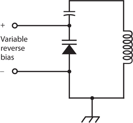
Some diodes are manufactured especially for use as variable capacitors. Such a device is known as a varactor diode, as you learned in the last chapter. Varactors find their niche in a special type of circuit called a voltage-controlled oscillator (VCO). Figure 20-9 shows an example of a parallel-tuned LC circuit in a VCO, using a coil, a fixed capacitor, and a varactor. The fixed capacitor, whose value should greatly exceed the capacitance of the varactor, keeps the coil from short-circuiting the control voltage across the varactor. The schematic symbol for a varactor diode has two lines on the cathode side, as opposed to one line in the symbol for a conventional diode.

20-9 Connection of a varactor diode in a tuned circuit.
Oscillation and Amplification
Under certain conditions, diodes can generate or amplify microwave RF signals—that is, signals at extremely high AC frequencies. Devices commonly employed for these purposes include the Gunn diode, the IMPATT diode, and the tunnel diode.
Gunn Diodes
A Gunn diode can produce from 100 mW to 1 W of RF power output, and is manufactured with gallium arsenide (GaAs). A Gunn diode oscillates because of the Gunn effect, named after the engineer J. Gunn who first observed it in the 1960s while working for the International Business Machines (IBM) Corporation.
A Gunn diode doesn’t work like a rectifier, detector, or mixer. Instead, the oscillation takes place as a result of a quirk called negative resistance, in which an increase in the instantaneous applied voltage causes a decrease in the instantaneous current flow under specific conditions.
Gunn-diode oscillators are often tuned using varactor diodes. A Gunn-diode oscillator, connected directly to a horn-shaped antenna, gives us a device known as a Gunnplexer. Amateur-radio experimenters use Gunnplexers for low-power wireless communication at frequencies of 10 GHz and above.
IMPATT Diodes
The acronym IMPATT comes from the words impact avalanche transit time. This type of diode, like the Gunn diode, works because of the negative resistance phenomenon. An IMPATT diode constitutes a microwave oscillating device like a Gunn diode, except that it’s manufactured from silicon rather than gallium arsenide. An IMPATT diode can operate as an amplifier for a microwave transmitter that employs a Gunn-diode oscillator. As an oscillator, an IMPATT diode produces about the same amount of output power, at comparable frequencies, as a Gunn diode does.
Tunnel Diodes
Another type of diode that will oscillate at microwave frequencies is the tunnel diode, also known as the Esaki diode. Made from GaAs semiconductor material, the tunnel diode produces only enough power to function as a local oscillator in a microwave radio receiver or transceiver. Tunnel diodes work well as weak-signal amplifiers in microwave receivers because they generate very little unwanted noise. The low-noise characteristic is typical of GaAs devices.
Energy Emission
Some semiconductor diodes emit radiant energy when current passes through the P-N junction in a forward direction. This phenomenon occurs as electrons “fall” from higher to lower energy states within atoms.
LEDs and IREDs
Depending on the exact mixture of the semiconductors used in manufacture, visible light of almost any color can be produced by forward-biased diodes. Infrared-emitting devices also exist. An infrared-emitting diode (IRED) produces energy at wavelengths slightly longer than those of visible red light.
The intensity of the radiant energy from an LED or IRED depends to some extent on the forward current. As the current rises, the brightness increases, but only up to a certain point. If the current continues to rise, no further increase in brilliance takes place, and we say that the LED or IRED is working in a state of saturation.
Digital Displays
Because LEDs can be made in various different shapes and sizes, they work well in digital displays. You’ve seen digital clock radios, hi-fi radios, calculators, and car radios that use LEDs. They make good indicators for “on/off,” “a.m./p.m.,” “battery low,” and other conditions.
In recent years, LED displays have been largely replaced by liquid-crystal displays (LCDs). The LCD technology has advantages over LED technology, including lower power consumption and better visibility in direct sunlight. However, LCDs require backlighting in dim or dark environments.
Communications
Both LEDs and IREDs work well in communications systems because we can modulate their intensity to carry information. When the current through the device is sufficient to produce output, but not so great as to cause saturation, the LED or IRED output follows along with rapid current changes. This phenomenon allows engineers to build circuits for transmitting analog and digital signals over visible-light and IR energy beams. Some modern telephone systems make use of modulated light transmitted through clear glass or plastic cables, a technology called fiberoptics.
Special LEDs and IREDs, known as laser diodes, produce coherent radiation. The rays from these diodes aren’t the intense, parallel beams that most people imagine when they think about lasers. A laser LED or IRED generates a cone-shaped beam of low intensity. However, we can use lenses to focus the emission into a parallel beam. The resulting rays have some of the same properties as the beams from large lasers, including the ability to travel long distances with minimal decrease in intensity.
Photosensitive Diodes
Most P-N junctions exhibit conductivity that varies with exposure to radiant energy, such as IR, visible light, and UV. Conventional diodes aren’t normally affected by these rays because they’re enclosed in opaque packages! Some photosensitive diodes have variable DC resistance that depends on the intensity of the visible, IR, or UV rays that strike their P-N junctions. Other types of diodes produce their own DC in the presence of radiant energy.
Silicon Photodiodes
A silicon diode, housed in a transparent case and constructed so that visible light can strike the barrier between the P and N type materials, forms a silicon photodiode. If we apply a reverse-bias voltage to the device at a certain level below the avalanche threshold, no current flows when the junction remains in darkness, but current flows when sufficient radiant energy strikes.
At constant reverse-bias voltage, the current varies in direct proportion to the intensity of the radiant energy, within certain limits. When radiant energy of variable intensity strikes the P-N junction of a reverse-biased silicon photodiode, the output current follows the light-intensity variations. This property makes silicon photodiodes useful for receiving modulated-light signals of the kind used in fiberoptic communications systems.
Silicon photodiodes exhibit greater sensitivity to radiant energy at some wavelengths than at others. The greatest sensitivity occurs in the near infrared part of the spectrum, at wavelengths slightly longer than the wavelength of visible red light.
The Optoisolator
An LED or IRED and a photodiode can be combined in a single package to construct a component called an optoisolator. This device, shown schematically in Fig. 20-10, creates a modulated-light signal and sends it over a small, clear gap to a receptor. An LED or IRED converts the electrical input signal to visible light or IR. A photodiode changes the visible light or IR back into an electrical signal, which appears at the output. An opaque enclosure prevents external light or IR from reaching the photodiode, ensuring that the photodiode receives only the radiation from the internal source.

20-10 An optoisolator contains an LED or IRED at the input and a photodiode at the output with a transparent medium between them.
When we want to transfer, or couple, an AC signal from one circuit to another, the two stages interact if we make the transfer through a direct electrical connection. The input impedance of a given stage, such as an amplifier, can affect the behavior of the circuits that “feed power” to it, leading to problems. Optoisolators overcome this effect because the coupling occurs optically rather than electrically. If the input impedance of the second circuit changes, the first circuit “sees” no change in the output impedance, which comprises only the impedance of the LED or IRED. The circuits’ impedances, and the electrical effects thereof, are literally isolated from each other.
Photovoltaic Cells
A silicon diode, with no bias voltage applied, can generate DC all by itself if enough IR, visible, or UV energy strikes its P-N junction. We call this phenomenon the photovoltaic effect. Solar cells work because of this effect.
Photovoltaic cells are specially manufactured to have the greatest possible P-N junction surface area, thereby maximizing the amount of radiant energy that strikes the junction. A single silicon photovoltaic cell can produce about 0.6 V of DC electricity in daylight. The amount of current that it can deliver, and therefore, the amount of power it can provide, depends on the surface area of the junction.
We can connect photovoltaic cells in series-parallel combinations to provide power for solid-state electronic devices, such as portable radios. The DC from these arrays can charge batteries, allowing for use of the electronic devices when radiant energy is not available (for example, at night or on dark days). A large assembly of solar cells, connected in series-parallel, is called a solar panel.
The power produced by a solar panel depends on the power from each individual cell, the number of cells in the panel, the intensity of the radiant energy that strikes the panel, and the angle at which the rays hit the surface of the panel. Some solar panels can produce several kilowatts of electrical power when the midday sun’s unobstructed rays arrive perpendicular to the surfaces of all the cells.
Quiz
Refer to the text in this chapter if necessary. A good score is at least 18 correct. Answers are in the back of the book.
1. Which of the following diode types can we use to produce ultra-high frequency (UHF) or microwave signals?
(a) Gunn
(b) Tunnel
(c) IMPATT
(d) All of the above
2. We’ll find an LED in
(a) a microwave oscillator.
(b) an optoisolator.
(c) a rectifier.
(d) a voltage regulator.
3. We can connect two diodes, as shown in Fig. 20-11, to obtain

20-11 Illustration for Quiz Question 3.
(a) oscillation.
(b) demodulation.
(c) amplification.
(d) clipping.
4. In a crystal-set radio receiver, the diode should have the smallest possible
(a) junction capacitance.
(b) forward-breakover voltage.
(c) avalanche voltage.
(d) reverse bias.
5. Diodes can work as frequency multipliers because diodes
(a) are nonlinear devices.
(b) can demodulate signals.
(c) require no external power.
(d) All of the above
6. What do we call a condition in which the current through a component goes down as the voltage across it goes up?
(a) Nothing! It can’t happen, so it has no name.
(b) Transconductance
(c) Negative resistance
(d) Current inversion
7. We input signals at 0.700 MHz and 1.300 MHz to a diode-based mixer. We get output at
(a) 0.500 MHz.
(b) 1.00 MHz.
(c) 0.600 MHz.
(d) All of the above
8. Which of the following diode types would we use in a circuit designed to measure the brilliance of a visible light source?
(a) A rectifier diode
(b) A photodiode
(c) A Zener diode
(d) An RF diode
9. Which of the following diode types would we use in a crystal set?
(a) A rectifier diode
(b) A photodiode
(c) A Zener diode
(d) An RF diode
10. When we apply negative voltage to a diode’s anode and positive voltage to the cathode, we sometimes get
(a) avalanche breakdown.
(b) forward bias.
(c) junction depletion.
(d) forward breakover.
11. In the circuit of Fig. 20-12, the diode’s nonlinearity allows it to function as a frequency multiplier. Nonlinearity also allows a diode to function as

20-12 Illustration for Quiz Question 11.
(a) a microwave oscillator.
(b) a signal mixer.
(c) an optoisolator.
(d) a PV cell.
12. Which of the following statements applies to the diode in a voltage-controlled oscillator (VCO)?
(a) It requires high voltage.
(b) It demodulates the signals.
(c) It operates in a state of reverse bias.
(d) It has low (almost no) resistance.
13. We’ll usually find a varactor diode in
(a) a voltage regulator.
(b) a rectifier.
(c) an optoisolator.
(d) a VCO.
14. We input a pure sine-wave signal to a circuit with a diode that introduces nonlinearity. Which of the following statements holds true for the output?
(a) It contains numerous signals at whole-number multiples (1, 2, 3, 4, etc.) of the input signal frequency.
(b) It contains numerous signals at whole-number fractions of the input signal frequency (1, ½, ⅓, ¼, etc.).
(c) It contains a signal at one and only one frequency: that of the input signal.
(d) We need more information to answer this question.
15. The maximum voltage that a solar panel assembled with silicon PV cells can produce depends on
(a) the number of cells in series, or in series-connected sets of parallel-connected cells.
(b) the number of cells in parallel, or in parallel-connected sets of series-connected cells.
(c) the surface area of the entire panel, regardless of how the cells are connected.
(d) Any of the above
16. The visible light emitted by an LED occurs as
(a) a result of avalanche effect.
(b) the reverse-bias voltage decreases.
(c) electrons lose energy in atoms.
(d) the PN junction gets hot.
17. What happens to the LC resonant frequency as we increase the reverse-bias voltage across the varactor in the circuit of Fig. 20-13, assuming that avalanche breakdown never occurs?
20-13 Illustration for Quiz Questions 17 and 18.
(a) It fluctuates.
(b) It goes up.
(c) It goes down.
(d) Nothing.
18. What would happen if the fixed capacitor in the circuit of Fig. 20-13 shorted out?
(a) The circuit would no longer amplify.
(b) Excessive current would flow through the varactor.
(c) The output voltage would become unstable.
(d) The inductor would short out the source of reverse bias meant for the varactor.
19. Which of the following diode types is manufactured for minimum junction capacitance so it can work as an RF switch?
(a) An IMPATT diode
(b) A “cat’s whisker”
(c) A PIN diode
(d) A Gunn diode
20. In which of the following devices does a photodiode serve an essential function?
(a) A rectifier
(b) An optoisolator
(c) A frequency multiplier
(d) A VCO