
5
Topology on a Humanoid Head
Now that we have all of our topology constraints out of the way, we can finally try to apply them to a more complex model. This next part of the book will be focusing on just that, applying the rules that we learned in the previous four chapters and using them to create the topology for different models.
In this chapter, we will be introduced to the retopology of a humanoid character. We will start off with a brief description of retopology. We will start our topology with the head. This chapter will establish a process when laying out our topology that we will apply to all of our models in the future. We will focus on the areas of detail first, then work on connecting them together. In the case of the head, we will start with the face. Then on the face, we will break it down into its separate features.
In this chapter, we will be covering the following subjects:
- Introduction to retopology
- Retopology of the face
- Retopology of the ear
- Retopology of the back of the head
Introduction to retopology
To start off, we should talk about retopology. Retopology is a process in which you modify or completely redo the topology of a mesh. In Figure 5.1, you can see a mesh with bad topology before retopology on the left, and then after retopology on the right:

Figure 5.1 – Comparison of mesh with bad topology (left) and mesh after retopology (right)
When approaching a retopology, it can be helpful to look at good examples of the process. You can see one of these references in Figure 5.2.
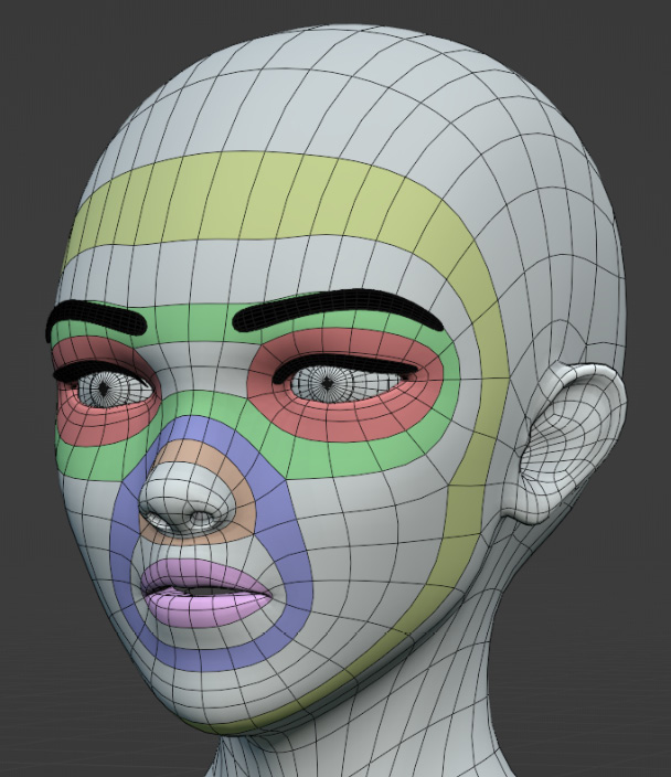
Figure 5.2 – An example of a topology reference that I have made
These are nice to get an idea of where our defining loops might be, but when modeling anything other than a basic human, the topology will likely be different. That is why we chose a bit more of a unique model to retopologize. This will give us a chance to look at the reasons we put the topology where we do and form a practical understanding through the application of our topology rules.
Revising topology checks and rules
It might be helpful if we list these rules all in one place, as we have learned quite a bit in the previous four chapters and it would be good to recap what we have learned and highlight the points of importance before we continue onward.
Foundational checks
There are three foundational topology checks to pay attention to first and foremost. The other topology rules will be hard to check if these first three conditions are not met:
- All of the faces on the model are quads: they each have four vertices and four edges
- There is no duplicate geometry
- All of the face normals are oriented in the same direction so that you cannot see the back of the faces
Geometric topology rules
When all of the preceding checks are satisfied, we can look at our first set of topology rules. These are the rules that generally direct you on how to lay out the topology on your mesh, as described in Chapter 2:
- All of the loops on a grid need to terminate into themselves, or into the void
- None of the loops can overlap themselves
- A loop cannot spiral around the mesh
These are the geometric topology rules because they pertain to just the shape of a model.
Deformation topology rules
Next, let us revise the topology rules we learned about in Chapter 3, which are responsible for ensuring good deformations:
- The edges of our grid need to be parallel to the axis of deformation
- The axis of twisting should be in line with the edge flow
- You should always put at least one row of faces between a pole and the specific areas of deformation
Because these rules apply to deformation, they are called the deformation topology rules.
Now that we have those rules refreshed, we can start on the retopology. When approaching retopology, you always want to start in the areas of detail first, the areas where you really need it to look in a certain way. For instance, the head has more detail than the chest. On the head, the face has more detail than the back of the head.
On the face, there are eyes, a nose, and a mouth. So, on a head, you would start with those individual features, then connect them to make the face, and then fill out the rest of the head. This way, we can make sure we have all of the details we need where we need them.
To start on our retopology of the head, we need to lay meshes over each other, and for this, we need to use snapping, which we covered in Chapter 2.
How to use snapping
Snapping allows us to snap any mesh selection to a face, edge, or vertex. To enable snapping, press the magnet at the top center of the viewport, as shown in Figure 5.3:

Figure 5.3 – The magnet icon, which enables snapping
By default, it is set to snapping to Increment. We want to change this to snap to faces. To change this setting, we need to press the arrow next to the magnet, and a menu like the one shown in Figure 5.4 should pop up.

Figure 5.4 – Menu to change snapping default settings
Now, if we select a vertex in a separate mesh, we can snap it onto one of the faces of another mesh. With that, we should be able to start on our retopology.
Retopology of the face
The model we will be using to learn how to apply good topology rules can be seen in Figure 5.5:

Figure 5.5 – Full body of the model to be used for retopology
The model has a unique face, which should give us an opportunity to stray from the topology guide and allow us to think about our topology beyond just copying from the reference. As said before, we want to start with the head because this is the area on the body with the most detail. On the head, we will start with the face for the same reason. In Figure 5.6, we can see the face a bit more clearly:

Figure 5.6 – Close-up of the face we will retopologize in this chapter
As you can see in the preceding figure, the face has many features to take into account including the mouth, nose, eyes, and ears. It is generally good practice to start by laying loops of vertices around any holes in the model.
Defining loops
Let us put a row of vertices around all the holes on the face including the eyes, nostrils, and mouth. In Figure 5.7, the loops of edges are all laid out:

Figure 5.7 – Face with vertices around all holes
To add these loops, I first added a plane, then deleted all but one of the vertices, and I extruded the vertices using the E hotkey until I had all of the cavities surrounded by a loop of edges. Do not worry too much about the number of vertices at this point, as we will change them as we work. Just try to add the lowest number that feels natural. Next, we will mark all of the major creases by doing the same thing. When you are done, it should look something like Figure 5.8:

Figure 5.8 – Face with vertices around all creases, valleys, and holes
Now that we have the creases and valleys marked, we can look at the peaks/edges that are most prominent. Figure 5.9 shows you what this model looks like after marking those edges:
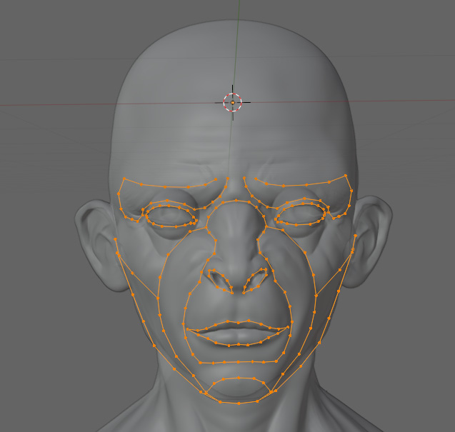
Figure 5.9 – Face with vertices around edges, creases, valleys, and holes
Now we can start to join these edges together. Remember, we are still trying to work from the areas of detail first, so do not be afraid to add more vertices to the areas that may not need them to accommodate the areas that do need those details in order to ensure a clean joining between the guiding edges.
Joining the edges
The place with the finest detail on this face is probably the eyes, so we can start there. In Figure 5.10, there is a closer view of the eye area:

Figure 5.10 – Close-up of the eye area with vertices
It is plain to see that the surrounding edges on the brow and the start of the cheek have far too few vertices to actually connect to the ones that we laid out on the eyelid. That is no problem because it is easy to add more. The loop cut tool is a great way to add more vertices to an edge. Just select the edge you want to modify, press Ctrl + R, and scroll up on the mouse wheel to add more vertices. After adding the vertices and snapping them to the face, it should look like Figure 5.11.
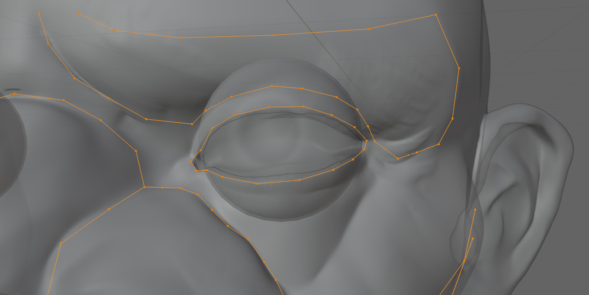
Figure 5.11 – Close-up of the eye with more vertices snapped to the face
Notice how the vertices are positioned to line up with each other as well. This will make it easier to join the faces together. To start joining the edges together, select two that line up nicely with each other, then press F. Figure 5.12 shows the first face that was made to connect the two strings of vertices:
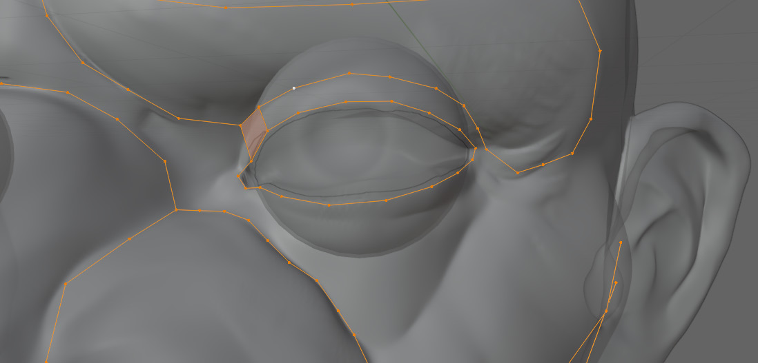
Figure 5.12 – First face connecting two strings of vertices
Next, we just need to fill in all of the joining edges around the eye. Now you should have a full loop of faces going around the eye, as in Figure 5.13:

Figure 5.13 – Full loop of faces around the eye
We can use Ctrl + R to check our topology, and that will show us that this loop follows all of our topology rules. From here, we can move on to the nose. We can get a closer look at the nose in Figure 5.14.
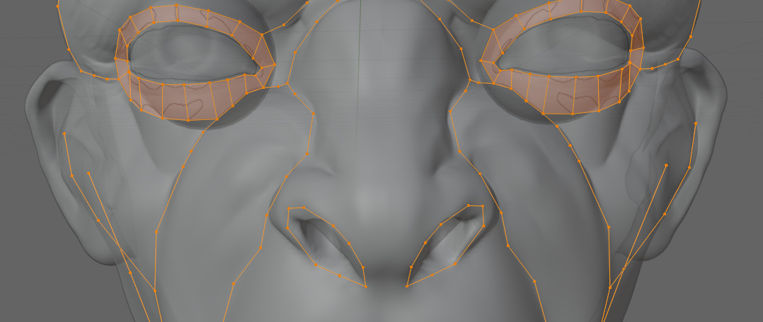
Figure 5.14 – A close-up of the nose with the first set of vertices
This shape is far more complex than the eye, so we should mark all of the edges and creases in this more focused section of the face. There are a few edges running down the bridge of the nose, and some creases around the nostrils that we have not marked as well. These are marked in Figure 5.15.
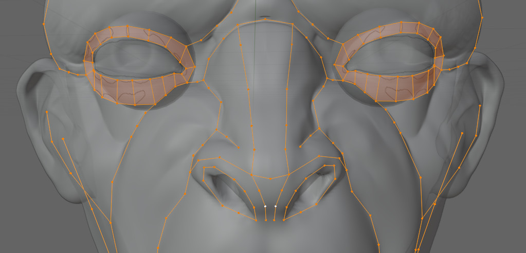
Figure 5.15 – The nose and nostrils with more detailed vertices
Notice how the number of vertices mostly line up with the edges next to them that were there previously. It is helpful to think ahead when laying out these edges because we are likely going to join them to the neighboring edges. With our new edges laid out, we can start placing our faces. First, we will start with the faces around the nose like in Figure 5.16.
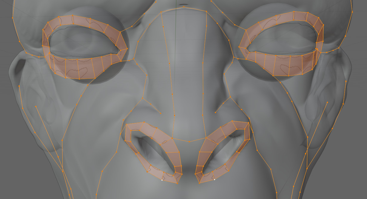
Figure 5.16 – Nose with faces around nostrils
With those loops done, we can work our way back to the bridge of the nose. All we have to do is join the edges that we have together, just like we did with the eyes. When you get back to the bridge of the nose, it will look like Figure 5.17:

Figure 5.17 – Nose with additional faces over the bridge
One big thing to notice here is the loop going around the nostrils. Because the nose is an extrusion from the relatively flat face, it should have a loop going around it just like our examples in the How should grids intersect? section in Chapter 2, when we extruded a face from a plane. You can see the two loops next to each other in Figure 5.18:

Figure 5.18 – The two adjacent nose loops
Now, we can do the same thing with the bridge of the nose, connecting all of the edges to form a clean grid:

Figure 5.19 – Forming a clean grid on the nose
With that done, you can run your loop cuts through all of the faces and find that they all follow our topology rules. With the nose done, there is one last major feature on the face, and that is the mouth. This is actually handled in a manner very similar to the eyes. Let us take a closer look at where we left the mouth in Figure 5.20.
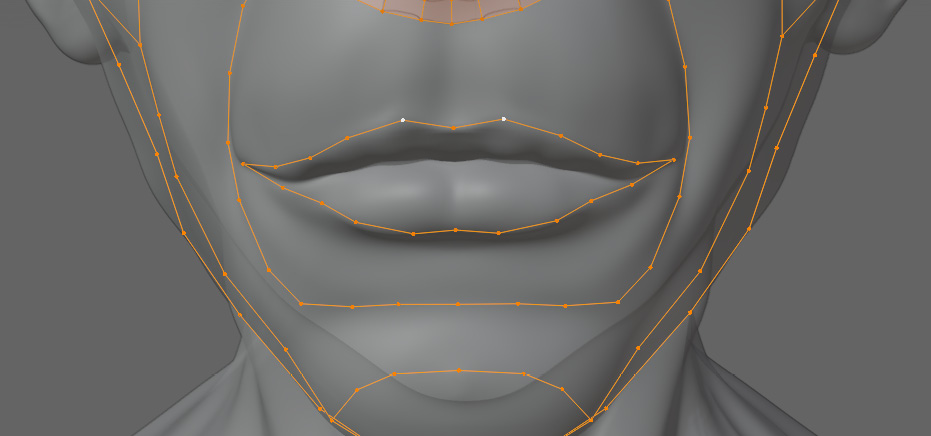
Figure 5.20 – Close-up of the mouth
With the mouth, we are just going to start by extruding the mesh on either side of the mouth loop by pressing E and snapping it to the faces. We can see the faces in Figure 5.21:
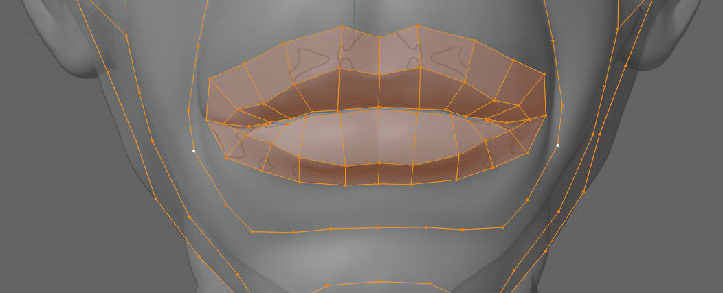
Figure 5.21 – Mouth with faces snapped over it
Now, we can take a step back and look at our vaguer major features. These are areas that are not as obvious as a hole or extrusion but still have a defined shape. A good area to start would be the selected edges in Figure 5.22:
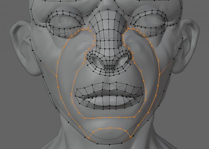
Figure 5.22 – Close-up of the next area to work on around the face and mouth
This part should be relatively simple, as all of the shapes seem to be forming a continuous loop around the nose and mouth. Figure 5.23 shows this area all filled in:

Figure 5.23 – The area around the face and mouth filled in with a looping grid
You might notice that the loop we made also flows up into the faces as well and has a very simple grid topology. This section also passes all of our topology rules. Next, we can do some work on the cheek in Figure 5.24.
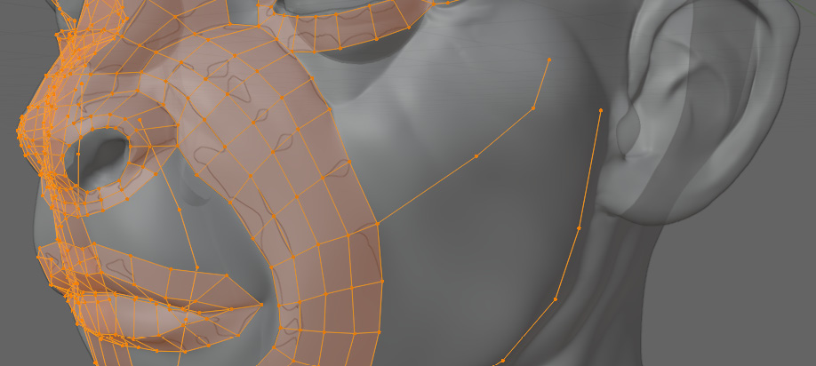
Figure 5.24 – Close-up of the cheek with guiding vertices
This topology should be even easier for us. We just need to extrude this face on either side of the guiding edge as well. Make sure to fill in the faces so that they roughly match the size of the rest of the quads on the face. You can see this in Figure 5.25.
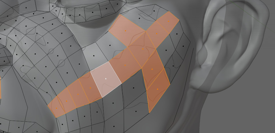
Figure 5.25 – Cheek filled with faces
This also follows our topology rules as it is just a simple grid deformed on the face of our character. With the cheeks done, there is not much left to fill out. Figure 5.26 shows us what is left:
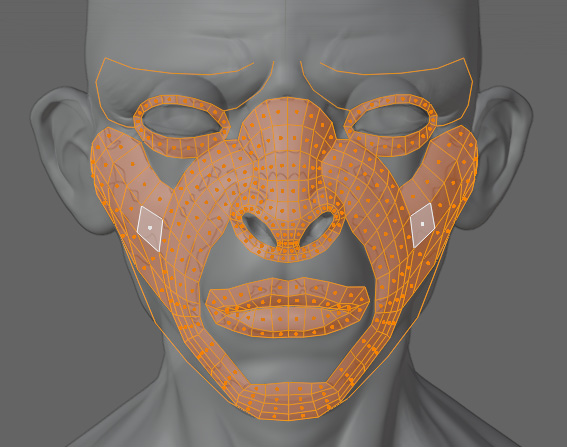
Figure 5.26 – Areas left on the face to retopologize
The brows are the last major shape we need to focus on before filling in all of the spaces in between. Figure 5.27 gives us a closer look at what we are dealing with.

Figure 5.27 – Close-up of eyebrow
The eyebrows look a lot trickier, but really, they are not much different from the other areas that we have looked at. All we are going to try to do is fit a simple grid into this space without violating our topology rules. It can be helpful to run a string of edges through the area that you are trying to fill to get a better idea of what path the faces want to naturally follow. Figure 5.28 shows this intermediate step.
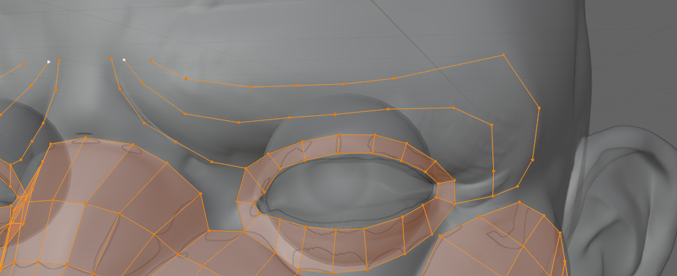
Figure 5.28 – Eyebrow with guiding edges
With the guiding edges in place, we can add our faces. It is the same technique as before: we just join the gaps with faces and adjust the vertices on the edges to line up properly. You can see the result in Figure 5.29.
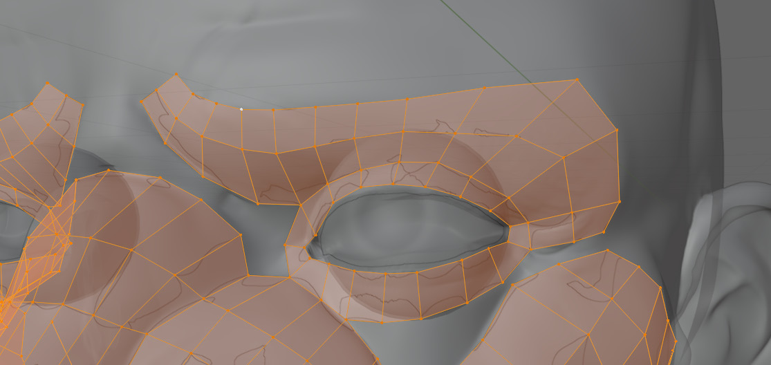
Figure 5.29 – Eyebrow guiding edges filled with faces
With that, all of the major shapes on the face have been defined. In Figure 5.30, we can take a look at all of the sections together.
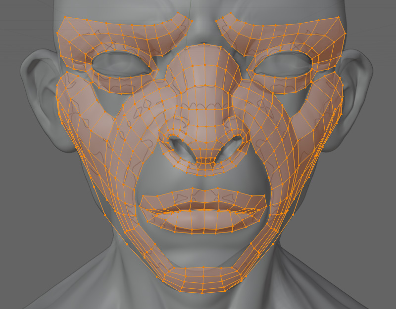
Figure 5.30 – Face with major shapes defined
Because all of our sections up until this point have followed all the topology rules, connecting the sections should be easy so long as we pay attention to our loops.
Joining the sections
The mouth has the most work, so we should start there. First, we will connect the two edges from Figure 5.31.
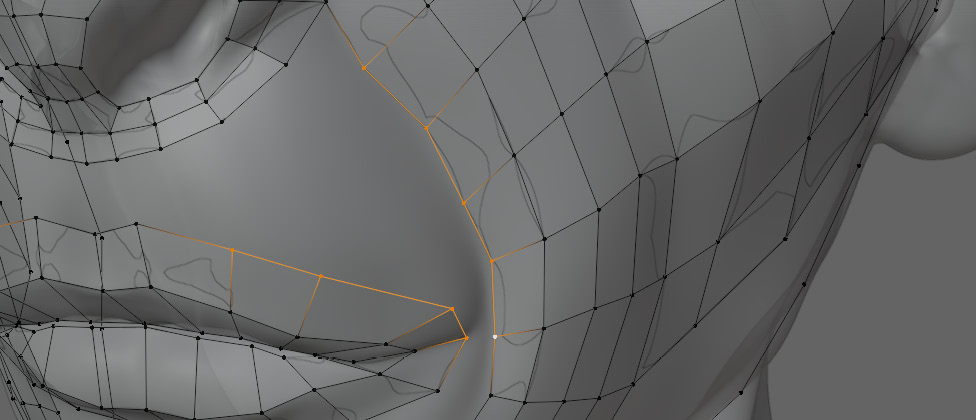
Figure 5.31 – The two edges on the face that will be connected first
Another guiding loop would definitely be helpful here. You can see this in Figure 5.32.

Figure 5.32 – Face with an additional guiding loop on the lip
Now we can start to join those faces. Figure 5.33 shows these edges connected:
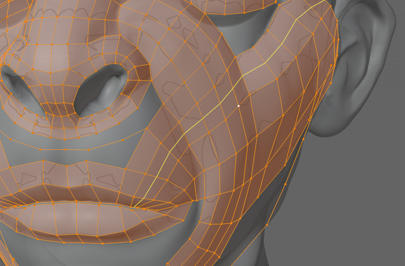
Figure 5.33 – Face with guiding edges connected
This connection does not break any of our rules, so now we just have to join the area between the nose and the mouth. First, we join the nose edges into the guide edges, as shown in Figure 5.34.

Figure 5.34 – Face with nose edges connected to guiding edges
And then finally, join the lip to the guide edges as well. Because the curvatures of the chin and the bottom of the mouth were so different, there are two guiding lines defining their curves. These are shown in Figure 5.35 along with the finished upper lip.
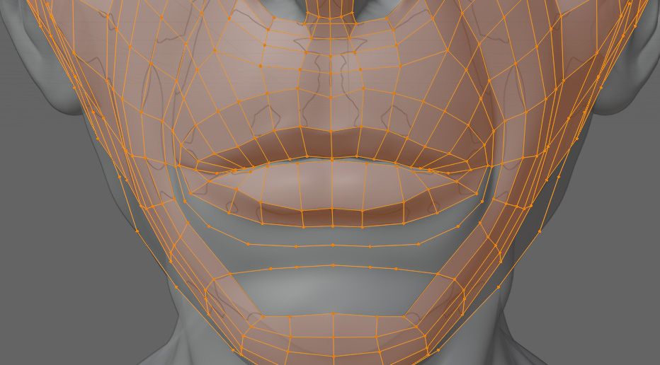
Figure 5.35 – Face showing areas remaining to be joined under the mouth
We are going to join these areas to the guiding edges just like we did on the top of the mouth. This can be seen in Figure 5.36.

Figure 5.36 – Face with most edges connected
Now, we have the eye area in Figure 5.37 to sort out.
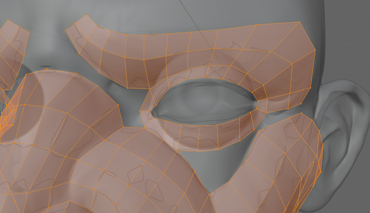
Figure 5.37 – The remaining eye area
This area is pretty messy and is going to be a bit more difficult to sort out. We will start with the easy part on the left. All we really have to do is join the faces directly to each other, and make sure they follow our topology rules. This is shown in Figure 5.38.
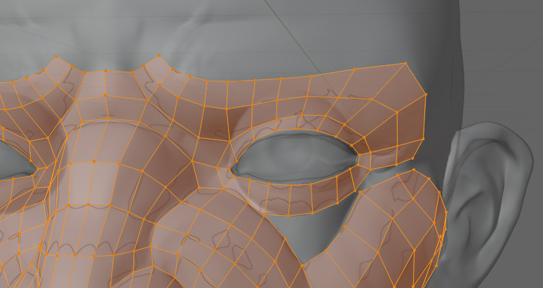
Figure 5.38 – Eye with edges joined on the left corner
Now we have to address the right side. The thing that makes this difficult is that this area is very triangular, and that is very much against our rules. To start, we are going to merge the vertices on the right corner of the eye and create a guide edge for the lower part, as shown in Figure 5.39.

Figure 5.39 – Close-up of eye with guide edge
Next, we just have to join our edges together, and it should look like Figure 5.40.

Figure 5.40 – Eye with all of the faces filled in
With the major sections done, there are a few housekeeping things we can do. Generally, it is a good idea to try and terminate our face loops into themselves, or into the void as often as possible; this reduces the opportunities for the mesh to overlap itself, or to not line up properly. In Figure 5.41, you might see what the issue could be highlighted by a loop cut.
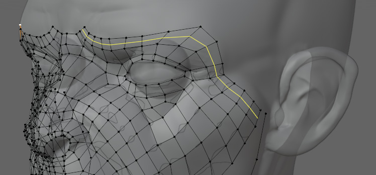
Figure 5.41 – Loop cut showing the potential issue
Because these edges are not going to terminate into any of the holes on the face, the highlighted edge is going to have to terminate into itself. As it is right now, we would have to keep track of the two ends of this loop of faces until we finally get them to loop back into themselves. If we join them like in Figure 5.42, we only have to manage one end.
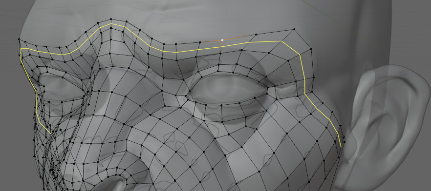
Figure 5.42 – Loop of faces joined at the top
We are going to repeat this on the chin, terminating the selected part in Figure 5.43 back into itself:

Figure 5.43 – Selected chin loop that needs to be terminated into itself
And in Figure 5.44, you can see the final loop:
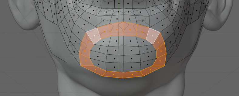
Figure 5.44 – Final loop on the chin terminating into itself
We only have the jaw left on the face, so we are going to fill that area next. In Figure 5.45, there is a closer view of his jaw with a guiding edge going through it:
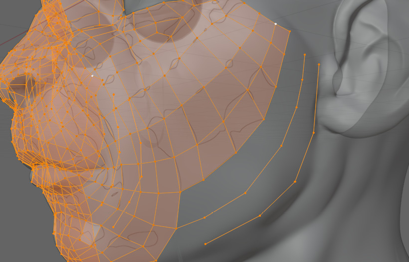
Figure 5.45 – Close-up of the jaw with guiding edges
And with the faces filled, it should look like Figure 5.46:

Figure 5.46 – Jaw with faces filled
And with that, we are done with the face. We can run loop cuts all around the face to find that all of the loops follow our rules. Now, we can take a look at some of the work we have done and the loops that make up the face. Figure 5.47 shows us all of the sections that we had originally laid out:

Figure 5.47 – A view of all the sections on the face
If you compare it to the original reference at the beginning of this chapter, you will notice that all of these colored sections look more or less the same. That is because a humanoid face will almost always have a nose, mouth, and eyes. When you model those, all that is left is joining them together. The white parts are the areas that are most likely to be different, as those are the areas that connect the features. That is why we always focus on the areas of detail first, making sure those areas follow our topology rules so that it is easy to join them together. The last difficult part of our head is the ear, and this is usually the most painful part of the head.
Retopology of the ear
Figure 5.48 shows us the ear we will be working on:
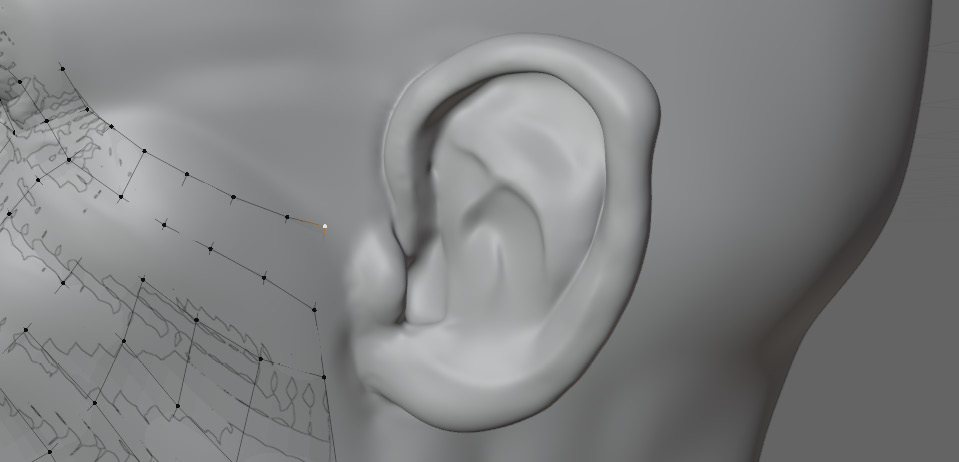
Figure 5.48 – Close-up of the ear
As we did for the face, we are going to map out the peaks and valleys, as shown in Figure 5.49:
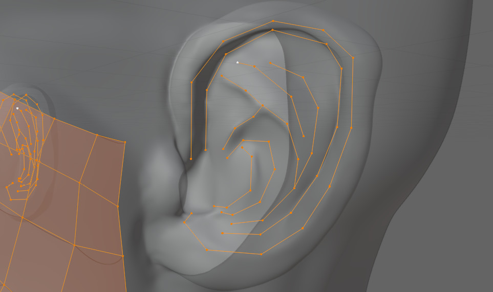
Figure 5.49 – Peaks and valleys defined with vertices on the ear
Then comes the agonizing task of joining the faces in a way that does not break topology rules. Unfortunately, there are not too many tricks here other than trial and error. Many 3D artists tend to use the ear to hide their messy topology. This is acceptable because the ear usually does not deform much, and is very easy to UV unwrap, even with bad topology. The level of detail in an ear, and its shape, can also radically change the topology required. For this reason, it is usually not worth potentially sinking hours into perfect ear topology. This ear ended up looking like Figure 5.50.
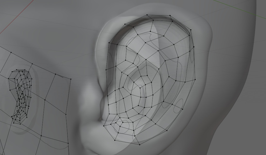
Figure 5.50 – Ear covered with faces
While it may not look like it, this ear actually follows all of our topology rules. With the inner part laid out, we can start to move to the outer part of the ear. Once you have worked your way all the way around the ear so that you have a ring of vertices surrounding it, as in Figure 5.51, we can start connecting it to the face.
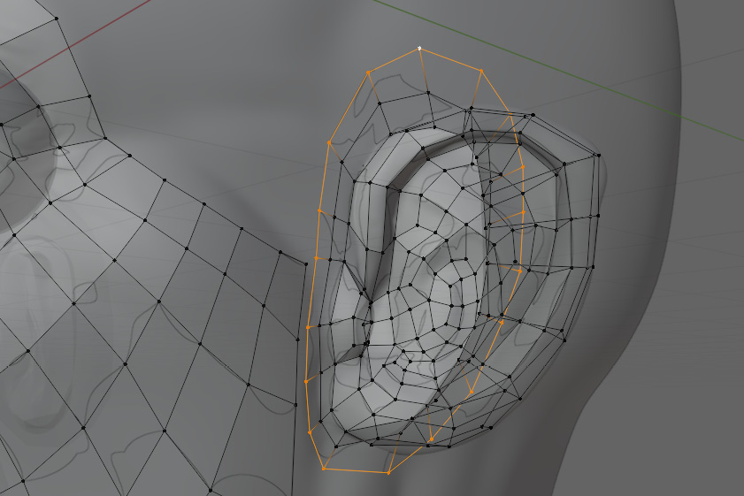
Figure 5.51 – Final loop going around the base of the ear
By adding the pole in Figure 5.52, we are able to split the faces to give us more geometry to join to the ear:

Figure 5.52 – Pole added to improve ear geometry and ease of joining
You could also loop-cut the face to add more geometry, but in this case, it would have made the face geometry too dense. Now that the vertices match up, we can merge the face to the ear, as in Figure 5.53.
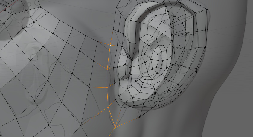
Figure 5.53 – Merging of the face and ear
With the ear done and connected to the face, we can start on the rest of the head.
Retopology of the back of the head
To begin with, we are going to join more of the ear to the head to get a flat line going across the two, as shown in Figure 5.54:
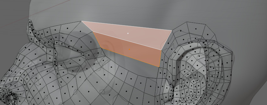
Figure 5.54 – Joining more of the ear to the head
Then we are going to loop-cut those faces to join into the rest of the face to match Figure 5.55:
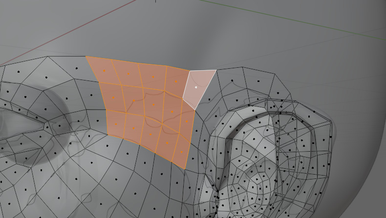
Figure 5.55 – Looping faces between the ear and face
Next, we are going to work toward the back of the head. Like the ear, the back of the head is not very important, so there is not too much to mess up here. To start, we are going to extrude the edges at the top of the area we just merged, as shown in Figure 5.56.
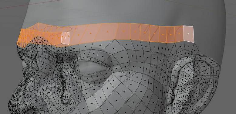
Figure 5.56 – Face with top edges extruded
Then, continue that loop to the back of the head, and add another loop across the top of the head, as in Figure 5.57.

Figure 5.57 – Adding guiding loops to the top of the head
These will act as our guides as we fill the areas in between, as you can see in Figure 5.58:
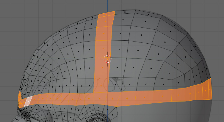
Figure 5.58 – A view of the guiding loops on and around the top of the head
And with that, the head portion of the model is done. We do not want to go too far down the back of the head because we may need to change things depending on how the head connects to the body.
Summary
In this chapter, you learned what retopology is. By now, you should know how to use snapping and how to retopologize a face, ear, and head.
This was a difficult chapter, far less direct than the previous ones. The most important thing to take away from this chapter is the process we used to break down the detailed sections and then bridge them together using our guiding edges. With the head out of the way, the most difficult part of the body is done. Now, we can take a step back and look at the rest of the body.
The next chapter will handle the rest of the body, starting with the hand. This is certainly a close second in difficulty to the head, but with our new knowledge from this chapter, we will confidently complete the task.