5
The Sound Plot
All designers utilize paperwork to help them organize, remember, develop, present, and produce their ideas. Scenic and costume designers think by way of drawing. Lighting designers develop a light plot, which is a scale drawing that shows where all of the lighting instruments are located in the theatre, how they are plugged in, and what color filter is used. Similarly, many sound designers use a sound plot to assist them throughout their design process.
The sound plot is a concise table of information detailing the sound and music cues of a production in order of occurrence—in essence, it’s a list of the sound cues. In its early stages, the sound plot identifies the cues and indicates their placement in the script. Later, the plot expands and includes more technical information regarding the production of the cues and the complete sound delivery system.
The information listed in the sound plot can be referred to when producing operator cue sheets (the instructions the sound operator uses to run the show; see ), or when organizing “to do” lists (e.g., for effects sources). Whenever discussing the sound design with the director, you should have the sound plot at hand as a quick reference and a convenient way of seeing the scope of your design. Often a sound designer and a composer will concern themselves with the consistency and symmetry of their design, in which case a concise overview of the cues can be quite useful. Seeing the entire scope of the cueing can help the designer budget the show in terms of time and money.
The sound designer usually revises a sound plot numerous times before the show opens. As the sound design evolves over the entire production period, be sure to keep the sound plot up to date.
THE PRELIMINARY PLOT
The preliminary sound plot may consist of only the information that you gleaned from your first or second read-through of the script. It could also include ideas that have evolved after various meetings. The preliminary sound plot should list how you refer to the cue (its name or description), its page number, and any notes that might be important. At this point, the plot might indicate where in the action of the play the cue happens and might offer a detailed description of the cue.
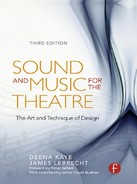
Figure 5.1 is an excerpt from a preliminary sound plot for a production of Measure for Measure. The entries “I, iv” and “Inside a nunnery” indicate which scene the effects are in and where that scene is set. Often—and especially with Shakespeare—a director will refer to sections of the play in terms of act and location (“The prison scene in Act IV”). Having scene and place information in the appropriate location on the sound plot points you to the proper spot in the play. Act and scene are written in Roman numerals to distinguish them from page numbers (in the script). The location information is written in lowercase to differentiate it from other comments or notes. Note the page 67 “FADE OUT BIRD” cue. Fadeouts are just as important as any played cue. It is necessary to define fade information so that you are aware of the flow of the cueing. Knowing the flow of the cueing means that you know what equipment is in use at any moment in the show. Understanding the flow of your design will become important when you start determining the structure of your playback system.
FIGURE 5.1 A preliminary sound plot.
Most sound plots are generated using a computer. Designers use database, spreadsheet, or word processing software for this task. Developing your plot using a database program allows you to make as many layouts for your cue information as necessary. You might make a separate plot for the director and stage manager with just page number, effect, and notes on it. If the director and the stage manager have to wade through too much nonessential information, they may resist referring to your plot during the rehearsal process. Another layout could be used to make cue sheets. When using a database application to make your sound plot, you should assign each cue a number. This will make it possible to sort your cues in order of their occurrence.
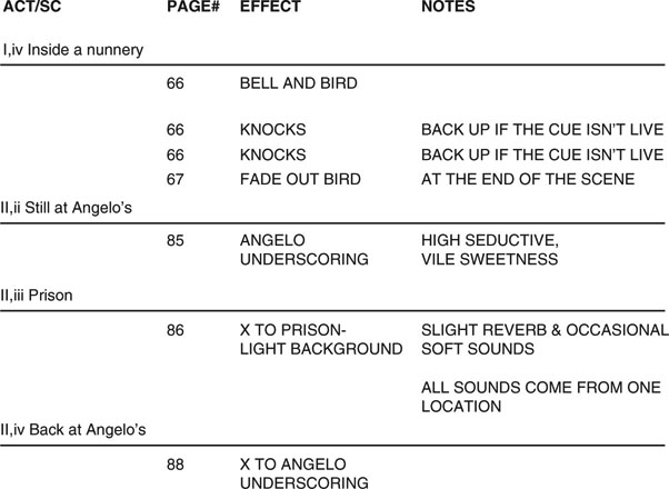
Creating your sound plot in a database system allows the designer to track all the cue-running detail on a laptop or desktop computer. Many designers make their own systems for this purpose. Figures 5.2 and 5.3 show some screenshots from a sound plot created in a FileMaker Pro database template.
FIGURE 5.2 An excerpt of a cue summary from a production of Rosencrantz and Guildenstern Are Dead.
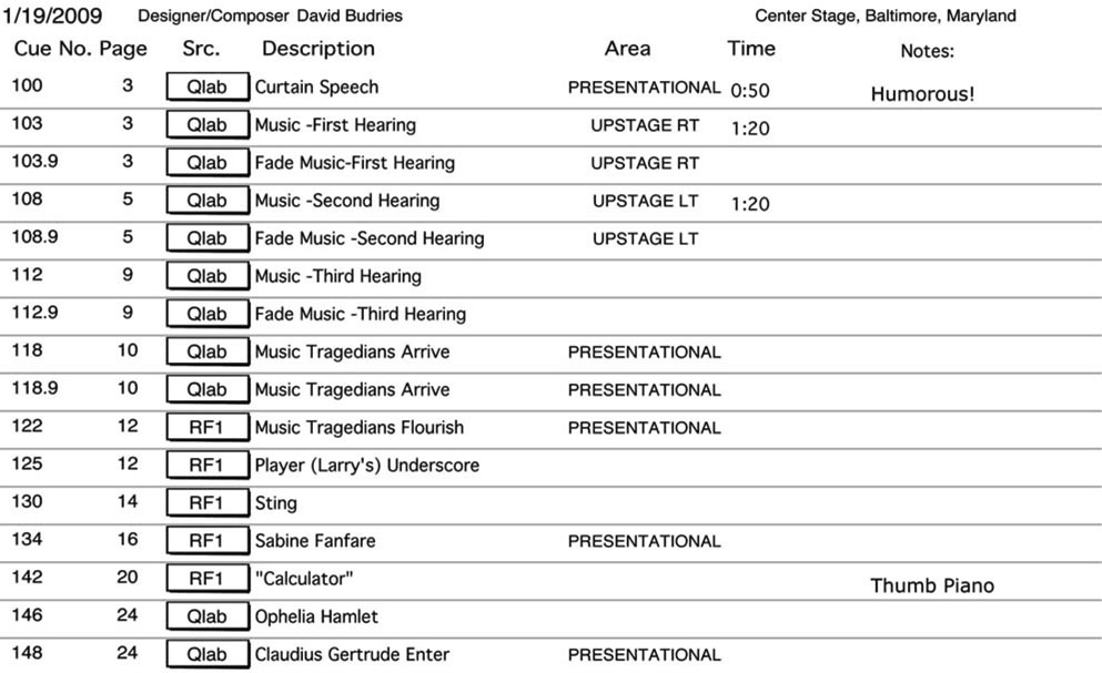
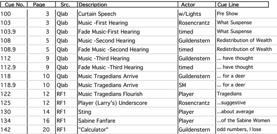
FIGURE 5.3 A cue line summary layout from the same production.
The term Src, or source, in Figure 5.2 refers to the source of a sound, whether it’s a microphone, CD, MD, deck, synthesizer, sampler, crash box, or computer-assisted playback system. Note that we use Src as a generic term for any source of sound. When filling out your plot, include any source that produces sound (samplers, CD players, cassette decks, and even microphones) under the category Src.
SUBSEQUENT SOUND PLOTS
After you and the director have met and talked through the show, you will undoubtedly make some changes in your approach to the design. Ideally, you and the director will have established a conceptual starting point for the development of the aural elements of the production. Using the notes from this meeting, revise your sound plot to reflect any changes. You might want to distribute this revised plot to the director, since it can serve as a guide to remind him of where you both decided sound might fit into the production. Later plots also contain technical information regarding loudspeakers, sources, track numbers, and, if you haven’t already added them, cue numbers.
These additional technical notes aren’t as important to others who see your plot (the director or stage manager) as they are to you, but such notes will assist you in manufacturing the cues.
The next item added to your plot would be the loudspeaker assignment for the cue, indicating either a single loudspeaker or a group of loudspeakers. A group is sometimes referred to as a distribution area. Information such as which playback source (SRC) is used and what output channels on the device are used may also be determined at this time.
Figure 5.4 is an excerpt from the final sound plot from the production of Measure for Measure seen in Figure 5.1. Notice how, over the course of rehearsals, the sound design has developed substantially. Initially, there were no sound cues on the plot until I, iv; now there are five before that point. The page 66 “BELL AND BIRD” sound cue that was to introduce the nunnery was replaced by the sound of nuns chanting. Added to the headings on the plot are columns for cue number, the source (SRC), speaker assignment, and what tracks are being used. The notes column has evolved from jottings about the function or nature of the cue to details that will assist in the building and teching of the show.
FIGURE 5.4 The first sound plot, revised.

In Cue 2, the “1 & 2” under TRX indicates that tracks 1 and 2 are going to be used for this cue. Under notes for Cue 2, “1) BELLS 2) TICKS” tells what effects are going to the first and second tracks in that cue. This needs to be figured out before transferring your cues to the playback device. In this example, “A” and “B” under SRC refer to two CD players. When making your cues, it’s easier to consult the sound plot to determine what effects should go on which tracks than to figure it out as you go.
Once the production is in technical rehearsals, the sound plot has all of the basic information about a cue that the designer needs for quick reference. Notes like “SOFT, DIST. FADE IN” remind the designer how a cue should be executed. By having track notes like “1) BELL 2) TICKS” on the sound plot, the designer can tell the operator the proper track to adjust when a change is desired. Many designers keep their own set of cue sheets so that they have complete information about each cue readily available. The sound plot comes in handy because it uses fewer pages to describe the cues since it is less detailed than the cue sheets.
As soon as you’ve decided where the sound cues will come from (their location in the space), you should consider making a simple sketch of your system in plan view (bird’s eye view) and label your individual loudspeakers and loudspeaker areas. Label loudspeaker areas by their function: front fill, high center fill, surrounds, for example. If your console output assignments are fixed, then you can add that to this drawing as well. This (as in lighting design) is often called a magic sheet. For larger systems, these can get quite complex and may have to be expressed on multiple sheets. Once you have this guide, you can easily make your loudspeaker assignments.
Most designers set up their own convention for identifying the loudspeakers. Some refer to the loudspeakers by letters (speaker A, B, C), some by numbers. If you’re using a simple four-speaker system—two speakers over the stage, two in the rear of house—you could label them A through D, starting to your left and moving clockwise. With more complicated setups, designers often name the loudspeakers by number and location (upstage left) or by function (kitchen radio). This approach is more precise and less confusing to you, the audio engineer and the operator. If more than one loudspeaker is being used at a time, label them in a way that refers to the function of the grouped loudspeakers (or loudspeaker area). If you’re using all of the loudspeakers out in the house, naming this group “house mix” on your plot should indicate to what loudspeakers the cue is sent.
SOURCES OR PLAYBACK DEVICES
Manually operated designs should be constructed with ease of operation in mind. Even a show running on a computer-assisted playback system will benefit from a well-thought-out, organized design. This is not to say that you must avoid tricky cueing sequences—even when manually cued, most sequences can be operated with enough practice. But the fewer changes your sound operator has to make at the mixer, the less chance there is for error.
As you scan the sound plot, you might see cues that are similar. If a script indicates one thunder cue, it will probably need at least five or more. If you are operating manually using a simple system, dedicate a specific playback device and a specific channel to those thunder cues. This will simplify operation by reducing the number of times that the sound operator needs to reassign inputs. If there are different cues in the scene that play out of different loudspeakers, put them on another playback device. If that is impossible and other cues come between the thunder cues, record them on a track that you’re not using. Logical planning will cut down on the number of moves the operator has to make. Organizing the effects using various decks is not difficult if you use the sound plot to see the overall picture of the design. Putting similar cues on the same playback device and track can also save you time during the sound level session. The level-setting session (see Chapter 9), which precedes the first technical rehearsal, is where preliminary volumes are set for the cues. The sound designer usually needs double the time that the theatre allows for a level-setting session—in fact, some theatres do not provide for a level session at all. By having similar cues on one deck and track, you can set the level for one transition music cue and thus approximate that level for all of them. Many shows start out with preshow and/or lead-in music, cues that usually come from the house loudspeakers, as opposed to effects speakers or those used for underscoring onstage. There are often other framing cues in the show (see Chapter 2). Once you’ve set the preshow music, you’ll be familiar with its qualities—its loudness, presence, and texture. And chances are that other cues of the same type (intermission music, postshow music) will demand similar presentation. To set the sound level of the intermission music, you can look back at your notes for the preshow and try those settings as a logical starting point. By using one speaker setup and limiting the framing effects to the same playback device, you can cut down on the reassigning that your operator will have to do while establishing a reference point by which you can estimate the settings for the other cues.
TRACKS
In addition to keeping similar cues on the same playback device and track, there are other considerations in choosing a track for recording music or effects. Is the cue going to be presented in mono, stereo, or in a multichannel mix? When a show is operated manually, it is essential to look at the speaker assignments of the playback device channels in preceding cues. Doing so allows you to distribute your cues so that the sound operator doesn’t have to reassign inputs on the mixer more than necessary. Is there going to be a crossfade from one loudspeaker (or group of loudspeakers) to another?
In most circumstances, a mono cue should be recorded on one channel. If only one channel is used for a mono cue, the other channel(s) can be preset for cues (except for volume) later in the show. If it means cutting down on the amount of reassigning for the sound operator, then using two channels for mono is acceptable. This situation can occur when a mono cue is sandwiched between two stereo cues. Also, it is usually easier to crossfade between loudspeakers by crossing input faders. Crossfading from a group of house loudspeakers to a set of underscoring speakers upstage is simple whenever two faders have the same program material. Assign one fader to the house speakers and the other to the underscoring speakers. This is easier than trying to move a number of output faders at one time.
CUE NUMBERS AND LETTERS
Cues need to be labeled sequentially so that the designer, sound operator, and stage manager can identify them. Numbering sound cues is the practice of many designers, but some designers and stage managers prefer to label sound cues by letter. They feel this helps separate sound cues from light cues, which seem always to be numbered. When using the lettering system, most designers avoid the letter Q. If the stage manager calls “Cue Q,” it sounds like a stutter and can be easily misunderstood. Once you get to Z, go to AA as a cue label.
FIGURE 5.5 A sound plot or cue summary.

When inserting a cue under this lettering system, the most common approach is to add a number after the letter: a cue inserted between Cue C and Cue D would be called Cue C1. Under the numbering system, an inserted cue will be a point cue (utilizing a decimal point) or will use a letter (starting with A) after it. Thus, a cue added between Cue 4 and 5 will either be Cue 4.5 or Cue 4 A. Letter or number the cues late in the sound design process to keep the number of point or “A” cues to a minimum, since these cues can be cumbersome for the stage manager to call.
While the lettering system can work for smaller, manually operated shows, a numbering system is essential when you create a sound plot using a computer-based system. Additionally, when using a database application for creating your sound plot and other paperwork, a cue number must be entered for each record. Typically, the cue number is the reference used for sorting cues. This technique requires that you leave some space between cues for new ideas (cues) to be inserted. Consider using a different numbers sequence from the lighting designer. If lighting starts with Q1, then you can start with Q100 or 200.
There are no hard and fast rules when it comes to numbering your cues. However, a rule of thumb for me is to use whole numbers for the beginning of any cue sequence, point cues (Q11.2) for internal moves within the cue, and.9’s (11.9) to stop or fade out a cue. I skip a few numbers before I label the next cue so that I leave room for cues that may get inserted into the cue sequence at a later time. This way, I shouldn’t have to renumber existing cues. There is no perfect system for numerical cueing, but it beats the daylights out of letters when you have a 300-cue show. The stage manager usually gets used to this system very easily.
—DB
Some designers choose to include other information on their plots, such as:
• Time, or length of the cue
• Timings of how long the play’s action that corresponds to the cue ran in rehearsal
• Count, or rate of execution of the cue (fade up or down, waits, etc.)
• Detailed notes about the construction or mixing of the cue and its options
• Detailed publishing information related to previously published materials used in the play
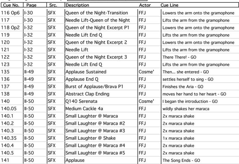
• Actor and cue line or action. (this is especially useful for a stage manager’s cue summary layout because it’s information that you want to share with them)
Figure 5.6 shows a variation of a sound plot, a stage manager’s cue summary. Developed using a database program, this summary shows only information that the sound designer believes to be relevant to the stage manager.
FIGURE 5.6 Stage manager’s cue summary.
THE LOUDSPEAKER PLOT
As sound designers have access to more complex systems for the playback of their work, many find that they need additional paperwork to assist them and those that work with them. One valuable item is the loudspeaker plot.
Just as you create a plot for your sound and music content, it is necessary to create a plot for your sound delivery system. As you begin to auralize the elements of your design (auralizing is imagining the sound in the theatrical space, as it takes place over time), you will begin to understand where you need to locate loudspeakers in order to create the aural illusions or effects that support the production.
When you listen to music or sound from your home stereo or headphones, you’ll probably notice that some of the sounds appear to spread out in front of you. In some situations you might perceive sound from behind, above you, or even in your head. If this level of illusion is possible with two loudspeakers, consider the complex imagery that might be possible with multiple loudspeakers. In an extreme example, Jonathan Deans designed a sound delivery system for Cirque du Soleil’s Las Vegas production of LOVE using 6039 custom loudspeakers. Can you imagine the illusory possibilities of that system? You, however, might consider a simpler arrangement of loudspeakers around the perimeter of your theatre. With a sixteen-channel delivery system, it will be possible to create a number of workable aural illusions. Of course, the more loudspeakers you add, the more control you will need. The bottom line is that it will be necessary for you to learn how to arrange and control multiple loudspeakers in order to create the desired effect. Drawing these loudspeakers positions in section and plan view will constitute a loudspeaker plot. This is an essential part of any professional sound design.
Another possibility when designing an arrangement of loudspeakers is to group a number of units doing the same job into a distribution area. Having a number of loudspeakers working together can be a very effective way of creating either a directed or diffuse aural image, depending upon how the loudspeakers are arrayed or placed.
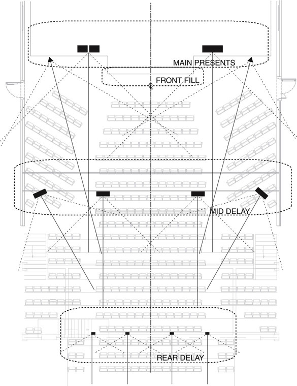
Figure 5.7 is a plan view drawing identifying distribution zones. This drawing shows four zones: main presents, front fill, mid delay, and rear delay. The solid line from each speaker is the on-axis point, which shows how to aim the loudspeaker on the horizontal plane. You’ll need a section view drawing to present the focus of the loudspeakers on the vertical plane. The dotted lines are the 6 dB down points—where the volume of the loudspeaker becomes 6 dB lower than the volume at the loudspeaker.
FIGURE 5.7 A loudspeaker distribution area drawing.

The needs of the production and the preferences of the designer will determine the format of the sound plot. Because different designers want different information to be readily available, the composition of a sound plot will be an individual choice. Regardless of which setup you choose, in the end, a sound plot is an invaluable means of organizing your work.