
9. Design for Fault Tolerance and Graceful Failure
In our experience, the second most common scalability related failure behind “Not designed to scale” is “Not designed to fail.” While this may sound a bit odd, it is in fact the most common type of scale failure in sites that are designed to be nearly infinitely scalable. Very often, small unexpected failures of certain key features will back up transactions and bring the whole business to its knees. After all, what good is a site that can scale infinitely if it isn’t resilient to failures? We all know that there is no way around systems or software failing, and as we add systems and software, our rate of failure will increase. While increasing our number of systems and associated services 1000x may not result in 1000x more failures, we should expect some significant increase. If we can’t handle this increase in failures, have we really delivered on the promise of scalability to our business? We think not.
In our business, availability and scalability go hand in hand. A product that isn’t highly available really doesn’t need to scale and a site that can’t scale won’t be highly available when the demand comes. As such, you really can’t work on one without thinking about the other. This chapter offers rules that help ensure sites can both scale AND be resilient to and tolerant of failures while still delivering value to the customer.
Rule 36—Design Using Fault Isolative “Swimlanes”
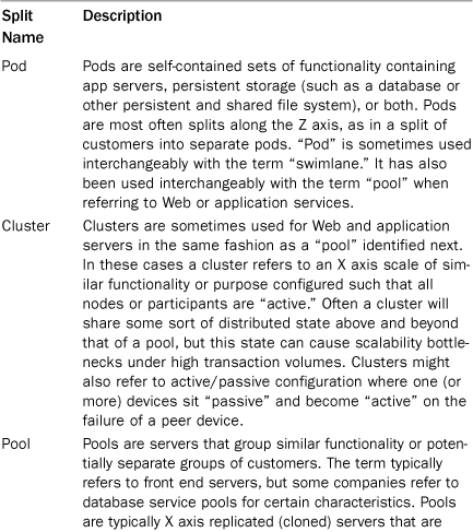
Our terminology in splitting up services and data is rich with confusing and sometimes conflicting terms. Different organizations often use words such as pod, pool, cluster, and shard. Adding to this confusion is that these terms are often used interchangeably by the same organization. In one context, a team may use “shard” to identify groupings of services and data while in another it only means the separation of data within a database. Given the confusion and differentiation in usage of the existing terms, we created the term swimlane in our practice to try to hammer home the important concept of fault isolation. While some of our clients started adopting the term to indicate fault isolative splits of services or customer segmentation in production, its most important contribution is in the design arena. Table 9.1 is a list of common terms, their most common descriptions, and an identification of how and when they are used interchangeably in practice.

From our perspective, the most important differentiation among these terms is the notion of design. Whereas pool, shard, cluster, and pod might refer to either how something is implemented in a production environment or how one might split up customers or services, swimlane is a design concept around creating fault isolation domains. A fault isolation domain is an area in which, should a physical or logical service fail to work appropriately, whether that failure is in a slow response time or an absolute failure to respond, the only services affected are those within the failure domain. Swimlanes extend the concepts provided within shards and pods by extending the failure domain to the front door of your services—the entry into your data center. At the extreme it means providing separate Web, application, and database servers by function or fault isolation zone. At its heart, a swimlane is about both scalability and availability, rather than just a mechanism by which one can scale transactions.
We borrowed the concept from CSMA/CD (carrier sense multiple access with collision detection—commonly referred to as Ethernet), where fault isolation domains were known as collision domains. To offset the effects of collisions in the days before full duplex switches, Ethernet segments would contain collisions such that their effects weren’t felt by all attached systems. We felt the term swimlane was a great metaphor for fault isolation as in pools the lines between lanes of swimmers help keep those swimmers from interfering with each other during the course of their swim. Similarly, “lines” between groupings of customers or functionality across which synchronous transactions do not occur, can help ensure that failures in one lane don’t adversely affect the operations of other lanes.
The benefits of fault isolative swimlanes go beyond the notion of increasing availability through the isolation of faults. Because swimlanes segment customers and/or functionality shared across customers, when failures occur you can more quickly identify the source. If you’ve performed a Z axis segmentation of your customers from your Web servers through your persistence tier, a failure that is unique to a single customer will quickly be isolated to the set of customers in that swimlane. You’ll know you are looking for a bug or issue that is triggered by data or actions unique to the customers in that swimlane. If you’ve performed a Y axis segmentation and the “shopping cart” swimlane has a problem, you’ll know immediately that the problem is associated with either the code, database, or servers comprising that swimlane. Incident detection and resolution as well as problem detection and resolution both clearly benefit from fault isolation.
Other benefits from fault isolation include better scalability, faster time to market, and lower cost. Because we focus on partitioning our systems, we begin to think of scaling horizontally, and hence our scalability increases. If we’ve separated our swimlanes by the Y axis of scale, we can separate our code base and make more efficient use of our engineers as discussed in Chapter 2, “Distribute Your Work.” As such, we get better engineering throughput and therefore lower cost per unit developed. And if we are getting greater throughput, we are obviously delivering our product to market faster. Ultimately all of these benefits allow us to handle the “expected but unexpected”: those things that we know will happen sooner or later but which we cannot clearly identify the impact. In other words, we know things are going to break we just don’t know what will break or when it will happen. Fault isolation allows us to more gracefully handle these failures. Table 9.2 summarizes the benefits of fault isolation (or swimlanes).
Table 9.2. Fault Isolation Benefits

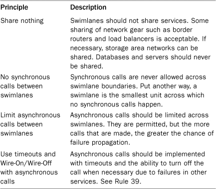
Having discussed why we should swimlane or fault isolate our product offerings, we turn our attention to the more important question of how to achieve fault isolation. We rely on four principles that both define swimlanes and help us in designing them. The first is that nothing is shared between swimlanes. We typically exempt major network components such as inbound border routers and some core routers but include switches unique to the service being fault isolated. It is also common to share some other devices such as a very large switched storage area network or load balancers in a smaller site. Wherever possible, and within your particular cost constraints, try to share as little as possible. Databases and servers should never be shared. Because swimlanes are partially defined by a lack of sharing, the sharing of servers and databases is always the starting point for identifying where swimlane boundaries truly exist. Due to the costs of network gear and storage subsystems these are sometimes shared across swimlanes during the initial phases of growth.
The second principle of swimlanes is that no synchronous calls happen between swimlanes. Because synchronous calls tie services together, the failure of a service being called can propagate to all other systems calling it in a synchronous and blocking fashion. Therefore, it would violate the notion of fault isolation if a failure of a service we hoped to be in one swimlane could cause the failure of a service in another swimlane.
The third principle limits asynchronous calls between swimlanes. While asynchronous calls are much less likely than synchronous calls to propagate failures across systems, there still exists an opportunity to reduce our availability with these calls. Sudden surges in requests may make certain systems slow, such as in the case of messages being generated subsequent to a denial of service attack. An overwhelming number of these messages may back up queues, start to fill up TCP ports, and even bring database processing of synchronous requests to a standstill if not properly implemented. As such, we try to limit the number of these transactions crossing swimlane boundaries.
The last principle of swimlanes addresses how to implement asynchronous transmissions across swimlane boundaries when they are absolutely necessary. Put simply, anytime we are going to communicate asynchronously across a swimlane, we need the ability to “just not care” about the transaction. In some cases, we may timeout the transaction and forget about it. Potentially we are just “informing” another swimlane of some action, and we don’t care to get a response at all. In all cases we should implement logic to “wire off” or “toggle off” the communication based on a manual switch, an automatic switch, or both. Our communications should be able to be switched off by someone monitoring the system and identifying a failure (the manual switch) and should sense when things aren’t going well and stop communicating (the automatic switche
These principles are summarized in Table 9.3.
Table 9.3. Fault Isolation Principles
How about the case where we want fault isolation but need synchronous communication or access to another data source? In the former case, we can duplicate the service that we believe we need and put it in our swimlane. Payment gateways are one example of this type of approach. If we were to swimlane along a Z axis by customer, we probably don’t want each of our customer swimlanes synchronously (blocking) calling a single payment gateway for a service like checkout. We could simply implement N payment gateways where N is the degree of customer segmentations or number of customer swimlanes.
What if there is some shared information to which we need access in each of these swimlanes such as in the case of login credentials? Maybe we have separated authentication and signin/login into its own Y axis split, but we need to reference the associated credentials from time to time on a read-only basis within each customer (Z axis) swimlane. We often use read replicas of databases for such purposes, putting one read replica in each swimlane. Many databases offer this replication technology out of the box, and even allow you to slice it up into smaller pieces, meaning that we don’t need to duplicate 100% of the customer data in each of our swimlanes. Some customers cache relevant information for read-only purposes in distributed object caches within the appropriate swimlane.
One question that we commonly get is how to implement swimlanes in a virtualized server world. Virtualization adds a new dimension to fault isolation—the dimension of logical (or virtual) in addition to physical failures. If virtualization is implemented primarily to split up larger machines into smaller ones, then you should continue to view the physical server as the swimlane boundary. In other words, don’t mix virtual servers from different swimlanes on the same physical device. Some of our customers, however, have such a variety of product offerings with varying demand characteristics of the year that they rely on virtualization as a way of flexing capacity across these product offerings. In these cases, we try to limit the number of swimlanes mixed on a virtual server. Ideally, you would flex an entire physical server in and out of a swimlane rather than mix swimlanes on that server.
Rule 37—Never Trust Single Points of Failure
In mathematics, singletons are sets that have only one element {A}. In programming parlance, the singleton pattern is a design pattern that mimics the mathematical notion and restricts the instantiation of a class to only one object. This design pattern is useful for coordination of a resource but is often overused by developers in an effort to be expeditious—more on this later. In system architecture, the singleton pattern, or more aptly the singleton antipattern, is known as a single point of failure (SPOF). This is when there exists only one instance of a component within a system that when it fails will cause a systemwide incident.
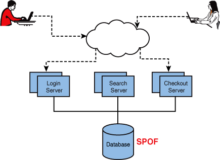
SPOFs can be anywhere in the system from a single Web server or single network device but most often the SPOF in a system is the database. The reason for this is that the database is often the most difficult to scale across multiple nodes and therefore gets left as a singleton. In Figure 9.1, even though there are redundant login, search, and checkout servers the database is a SPOF. What makes it worse is that all the service pools are reliant on that single database. While any SPOF is bad, the bigger problem with a database as a SPOF is if the database slows down or crashes, all services pools with synchronous calls to that database will also experience an incident.
We have a mantra that we share with our clients, and it is simply “everything fails.” This goes for servers, storage systems, network devices, and datacenters. If you can name it, it can fail, and we’ve probably seen it happen. While most people think of datacenters as never failing, we have personal experience with more than a dozen datacenter outages in as many years. The same goes for highly available storage area networks. While they are remarkably more reliable than the old SCSI disk arrays, they still can and do fail.
The solution to most SPOFs is simply requisitioning another piece of hardware and running two or more of every service by cloning that service as described in our X axis of scale. Unfortunately, this isn’t always so easy. Let’s retrace our steps to the programming singleton pattern. While not all singleton classes will prevent you from running a service on multiple servers, some implementations absolutely will prevent you from this without dire consequences. As a simplified example, if we have a class in our code that handles the subtraction of funds from a user’s account this might be implemented as a singleton to prevent unpleasant things from happening to a user’s balance such as it going negative. If we place this code on two separate servers without additional controls or semaphores it is possible that two simultaneous transactions attempt to debit a users account, which could lead to erroneous or undesired conditions. In this case we need to either fix the code to handle this condition or rely on an external control to prevent this condition. While the most desirable solution is to fix the code so that the service can be implemented on many different hosts, often we need an expeditious fix to remove a SPOF. As the last focus of this rule, we’ll discuss a few of these quick fixes next.
The first and simplest solution is to use an active-passive configuration. The service would run actively on one server and passively (not taking traffic) on a second server. This hot/cold configuration is often used with databases as a first step in removing a SPOF. The next alternative would be to use another component in the system to control the access to data. If the SPOF was a service, then the database can be used to control access to data through the use of locks. If the SPOF is the database, a master-slave configuration can be set up, and the application can control access to the data with writes/updates going to the master and reads/selects going to the slave. A last configuration that can be used to fix a SPOF is a load balancer. If the service on a Web or application server was a SPOF and could not be eliminated in code the load balancer can often be used to fix a user’s request to only one server in the pool. This is done through session cookies, which are set on the user’s browser and allow the load balancer to redirect that user’s requests to the same Web or application server each time resulting in a consistent state.
We covered several alternative solutions to SPOFs that can be implemented quickly when code changes cannot be made in a timely manner. While the best and final solution should be to fix the code to allow for multiple instances of the service to run on different physical servers the first step is to eliminate the SPOF as soon as possible. Remember, “everything fails” so don’t be surprised when your SPOF fails.
Rule 38—Avoid Putting Systems in Series
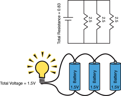
Components in electrical circuits can be connected in a variety of ways; the two simplest are series and parallel. Circuits in series have components such as resistors and capacitors that are connected along a single path. In this type of circuit the current flows through every component, and the resistance and voltage are additive. Figure 9.2 shows two circuits one with three resistors and one with three batteries and the resulting resistance and voltage. Notice that in this diagram if any of the components fail, such as a resistor blows, then the entire circuit fails.
Figure 9.2. Circuits in series
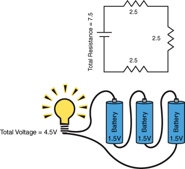
Figure 9.3 shows two parallel circuits, the top one with three resistors (and a voltage source or capacitor) and the bottom one with three batteries. In this circuit, the total resistance is calculated by summing the reciprocals of each resistance and then taking the reciprocal of that sum. The total resistance by definition must be less than the smallest resistance. Notice also that the voltage does not change but instead the batteries only contribute a fraction of the current, which has the effect of extending their useful life. Notice that in these circuits the failure of a component does not cause a failure across the entire circuit.
Figure 9.3. Circuits in parallel
The similarities between the architecture of your system and a circuit are many. Your servers and network gear are components. Some components in your system are Web servers, some are application servers, some are load balancers, and others are database servers. These can be connected in parallel or in series. As a simple example let’s take a static Web site that has a lot of traffic. You could put ten Web servers all with the same static site on them to serve traffic. You could either use a load balancer to direct traffic or assign all ten separate IP addresses that you associate with your domain through DNS. These Web servers are connected in parallel just like the batteries in Figure 9.3. The total current or amount of traffic that one Web server has to handle is a fraction of the total, and if one Web server fails the site remains available as it still has nine other Web servers.
As an example of a more typical architecture in series, let’s add some layers. If we take a standard three tier site that has a single Web server, one application server, and one database server then we have an architecture connected in series. For a request to be fulfilled, the Web server must accept it and pass a request to the application server, which queries the database. The application server then receives the data back, manipulates the data, and sends it back to the Web server, which finally fulfills the request to the customer. If any component in this circuit or architecture breaks, then the entire system is down.
This brings us back to your real world architecture. Almost always there are going to be requirements to have components in series. When you take into consideration the load balancer, the Web and application tier, the database, the storage system, and so on there are many components required to keep your system running. Certainly adding components in parallel, even when tiers are connected in series, helps reduce the risk of total system failure caused by a component failure. Multiple Web servers spread the traffic load and prevent a system failure if only one Web server fails. On the Web and application tiers most people readily acknowledge this concept. Where most people overlook this problem is in the database and network layers. If Web and application servers connected in parallel all are connected in series to a single database we can have a single component result in catastrophic failure. This is why it is important to pay attention to the rules in Chapter 2 about splitting your database and in Chapter 3, “Design to Scale Out Horizontally,” about scaling horizontally.
In regards to the network components we often see architectures that pay a lot of attention to connecting servers in parallel but completely ignore the network devices, especially firewalls. It is not uncommon to see firewalls inside and outside the network; see Rule 15 for further discussion regarding firewalls. In this case we have traffic going through a firewall, through a load balancer, through a firewall, through a switch, then to a Web server, an application server, a database server, and all the way back. There are at least seven components twice. So what’s the big deal about adding another component if you’re already going through a half dozen?
Items in series have a multiplicity effect on risk of failure. As a simple example if we have two servers in series, each with a 99.9% availability or uptime, then our total availability of the system cannot be greater than 99.9% × 99.9% = 99.8%. If we add a third component, in series, at the same 3-9’s availability of 99.9% we get an even lower availability of 99.9% × 99.9% × 99.9% = 99.7%. The more components that are placed in series, the lower the system’s availability. Table 9.4 lists some simple calculations that demonstrate the lowered availability and the resulting increase in downtime per month. For every component (at 99.9% availability) that we add to the system in series, we are adding ~43 minutes of downtime per month.
Table 9.4. Components in Series at 99.9% Availability
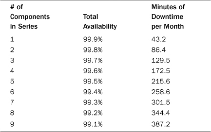
Because your system, just like most circuits today, are much more complicated than a simple series or parallel connection, the exact calculations for your expected availability are much more complicated than our simple example. However, what you can take away from this is that components in series significantly increase our system’s risk of experiencing downtime. You can of course mitigate this by reducing the items in series or adding multiple numbers of those components, in parallel
Rule 39—Ensure You Can Wire On and Off Functions
What: Create a framework to disable and enable features of your product.
When to use: Risky, very high use, or shared services that might otherwise cause site failures when slow to respond or unavailable.
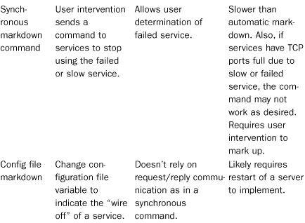
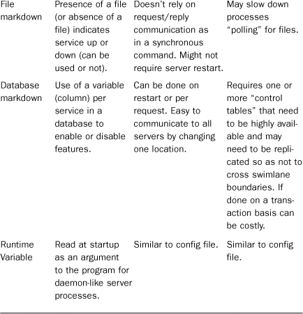
How to use: Develop shared libraries to allow automatic or on-demand enabling and disabling of services. See Table 9.5 for recommendations.
Table 9.5. Wire On/Wire Off Approaches

Why: Graceful failure (or handling failures) of transactions can keep you in business while you recover from the incident and problem that caused it.
Key takeaways: Implement Wire On/Wire Off Frameworks whenever the cost of implementation is less than the risk and associated cost of failure. Work to develop shared libraries that can be reused to lower the cost of future implementation.
We introduced the notion of what we call Wire On/Wire Off frameworks in Chapter 7, “Learn from Your Mistakes,” while discussing rollbacks and mentioned it again in this chapter while we were discussing fault isolation as a method of design. Ultimately these types of frameworks help to ensure that your systems can either fail gracefully (in the event of self-diagnosing frameworks) or can operate with certain functionality disabled by human intervention. Sometimes companies refer to similar functionality as Mark Up/Mark Down functionality or more simply enabling and disabling functionality.
There are several approaches for Wire On/Wire Off in the past, each with certain benefits and drawbacks. The approach to enabling and disabling services probably depends on the capabilities of your engineering team, your operations team, and the business criticality of the service in question. Table 9.5 covers some of these approaches.
Table 9.5 isn’t meant to be an all encompassing list of the possibilities for enabling and disabling functionality. In fact, many companies blend some of these options. They may read in variables from a database or a file at startup, but also implement synchronous communication and automatic failure detection. In the case of payment gateways they may decide to automatically “auth” credit cards for some period of time, and then past a threshold of time determined by their appetite for risk, decide to just queue authorizations and move to an asynchronous method of authorization.
Equally important issues to tackle when considering Wire On/Wire Off frameworks are the decisions of where and when they should be used. Clearly the work to implement the framework represents additional work and as a result additional cost to the business. Let’s start with the (unlikely and probably incorrect) position that certain features would never fail. If we could tell which features would never fail, we would never want to implement this functionality for those features as it represents a cost with no return. With that starting point, we can identify where this investment has value or provides the business with a return. Any feature that has a high rate of usage (high throughput) and whose failure will impact other important features on the site is a candidate. Another candidate is any feature that is undergoing fairly significant change in a given release. The idea in both of these areas is that the cost of implementing Wire On/Wire Off is less than the risk (where risk is a function of both likelihood of a failure and the impact of that failure) to our business. If the development of a feature with this functionality is an extra $1,000 and an unhandled failure of the feature might cost us $10,000 in business is the cost justified?
When done well, engineering teams can reduce the cost of implementing a Wire On/Wire Off framework by implementing a set of shared libraries to be used across functions. This approach doesn’t reduce the cost of implementing the framework to zero for any new development, but it does help to reduce the cost for future generations of framework-enabled features.
We recommend implementing Wire On/Wire Off frameworks for any shared, heavily used services such as payment gateways and computationally expensive processes such as the calculation of social network graphs. Any shared service is a shared failure point, and it is worthwhile thinking about how to work around that service should it fail. Any significant new development also carries risk equal to its development cost, and should at least be considered for such a framework. To be clear, we don’t believe that everything should be capable of being enabled and disabled; such an approach is costly and ill-advised. But well run teams should be able to identify risky and shared components and implement the appropriate safeguards.
Summary
We believe that availability and scalability go hand in hand. A product that isn’t highly available doesn’t need to scale because users will soon stop coming. A site that can’t scale won’t be highly available when the demand comes because the site will be slow or completely down. Because of this you can’t work on one without thinking about the other. This chapter offered four rules that help ensure your site stays highly available as well as continues to scale. Don’t let a focus on scalability cause you to forget how important availability is to your customer.