The purpose of this chapter is to expand on a number of concepts that have been introduced throughout the course of this book. Due to the prevalence and importance of these topics, it will be valuable to see more details about each so+ you can better understand how to incorporate them into your own architectures. These concepts will be written in a “problem-solution” format: the problem will be presented and a solution will follow. The solution will be a discussion that will go into varying degrees of detail aimed at allowing you to properly approach such challenges on your own.
The recipes that are included in this chapter are as follows:
Transport Protocols Within Event Handlers: This recipe looks at additional techniques for the communication of information from RFID event handlers to external components and services.
RFID Data, XML, and SQL Server: This recipe will help you discover approaches to dealing with data in XML to simplify the integration of different applications and platforms with BizTalk RFID.
Debugging Tips: There are a variety of components in a typical BizTalk RFID implementation, and it is valuable to understand how some of the most common can be tracked and debugged.
Integration with BizTalk EDI Functionality: It is fairly common to need to initiate the creation and delivery of EDI documents from an RFID read. This section will give an overview of how to deliver an EDI document in response to an RFID tag event.
Creating an XSD Based on RFID XML: Automating schema generation is an important skill when working with any type of XML.
12.1. Transport Protocols Within Event Handlers
Problem
There are a variety of protocols (HTTP, MSMQ, SOAP, FTP) that can be used within event handlers to post RFID information to external targets. How can I determine the appropriate protocol to use when architecting my solution?
Solution
Chapter 5 went into detail on how to work with event handlers, and Chapter 8 presented the steps needed for publishing information to an MSMQ from an event handler. The problem at hand is not how to build a custom event handler, but rather how to interact with external components, applications, and platforms using different transport protocols. The key to working with data publication within event handlers is understanding that the handoff portion of the code is easy to modify—an event handler can be swapped from posting to an MSMQ to posting to a web service with relative ease.
Before working through the different protocols, it is important to note that it is best practice not to put business rules and complex logic into an event handler. A simple handoff to a web service can be greatly complicated when taking into account things like exception handling, retries, transaction support, messaging patterns, and backup transport logic. When BizTalk Server is available, it is most appropriate to push the event publication to this platform using a transport protocol that is unlikely to present errors—for example, the path of the MSMQ (if the queue is on the local machine, it is highly unlikely that exceptions will occur). Letting BizTalk Server take on the workflow logic and the exception handling—for example, sorting and de-duplicating events—is an excellent way to keep BizTalk RFID event handlers simple and performant.
Architectural discussions aside, there are times when event handlers need to communicate directly using services (both web and WCF), file transports, HTTP, TCP/IP, and other protocols. Given what has already been illustrated around the MSMQ event handler (see Exercise 8-1), our solution will start with referring to this code base, and from there reach out to other protocols and handoff methods. The code of interest in the event handler is really contained in a single method, PostEvent. There is some code in the Init method that initializes the queue, and this should certainly be taken into account for other transport protocols; but the PostEvent method, with the single line of code that pushes a serialized version of the RfidEventBase object to the queue, is the primary point of interest (see Listing 12-1). With a reference to where the handoff is occurring for an MSMQ base event handler, you can now look at other protocols and substitute the MSMQ handoff with the new transfer protocol code.
Listing 12-1. The Original Post to an MSMQ in the PostEvent Method
private void PostEvent(RfidEventBase evt)

{

 ...

 try

 {

  destinationQueue.Send(SerializeEvent(evt)

   ,MessageQueueTransactionType.Single);

 }

 ...

}
WCF Services Transport
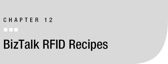
Consuming WCF services is quite easy, since the bulk of the work is done by a Visual Studio wizard. The first step to consuming WCF is to add a reference to the service in the event handler project. This can be done by right-clicking the project, selecting Add Service Reference (see Figure 12-1), and locating the WCF service to consume. This process will add a generated file to the project, with class definitions that can be instantiated from the event handler code.
![]() Note The .NET 3.5 Framework or later must be installed. Visual Studio 2005 can reference WCF services with the proper extensions deployed, but additional steps must be taken to add a service reference (i.e., this option is not available in the project context menu).
Note The .NET 3.5 Framework or later must be installed. Visual Studio 2005 can reference WCF services with the proper extensions deployed, but additional steps must be taken to add a service reference (i.e., this option is not available in the project context menu).
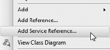
Figure 12-1. The Add Service Reference option in Visual Studio
Once the WCF service has been referenced, it can be called easily from the event handler. Assuming that the name of the client class is WCFClient, the code shown in Listing 12-1, which is the MSMQ post, could be replaced with the WCF code in Listing 12-2.
Listing 12-2. Updated PostEvent Using WCF
private void PostEvent(RfidEventBase evt)

{

 ...

 try

 {

  WCFClient client = new WCFClient();


  // the SerializeEvent will need to be based on what is

  // expected in the ProcessRfidMessage method. In this

  // case, if the SerializeEvent remains the same as it was

  // for the MSMQ post, it will pass an XML document version

  // of the event to the method.

  client.ProcessRfidMessage(SerializeEvent(evt));

  client.Close();

 }

 ...

}
Web Services Transport
Consuming web services is similar in nature to consuming WCF services. The difference is simply to select Add Web Reference from the project context menu instead of Add Service Reference (see Figure 12-2). In the dialog box, point to the web service to consume—and Visual Studio will take care of the rest. It will create all of the class reference information needed to call the web service. If you’re calling a web method with the same definition as ProcessRfidMessage in the previously described WCF service, the code update to the event handler will look identical to that shown in Listing 12-2.
Figure 12-2. Adding a web service reference in Visual Studio
File Transport
In the MSMQ event handler, log information is written directly to a file. It could easily be extended beyond the methods available in ILogger to those in System.IO. The method of delivering information by file could be valuable in several scenarios, but is generally relegated to logging information to a text file.
In truth, it would make sense to remove this logging from the event viewer and push it into a commonly referenced assembly or a BizTalk orchestration, so that all event handlers and other components can use the same approach to logging. Logging to a file today may need to be extended to include a database table tomorrow. Rather than having to update all of the event handlers separately, the single point of common logging (the assembly or the orchestration) could be updated.
Discussion
It should be quite clear from the protocols outlined in the discussion that swapping from one transport protocol to another in an event handler should be extremely easy. There are no technical limitations to how information is pushed from an event handler to an external application or client. The art is in determining the appropriate architecture—whether an event handler should call directly to a web service or not depends on the amount of workflow and exception handling that may need to be performed.
12.2. RFID Data, XML, and SQL Server
Problem
There is a lot of information I would like to store in a database related to BizTalk RFID information, but I am not sure of the most appropriate way to do this. Additionally, I am trying to determine how best to query the data to return it to external systems. Some of the information is stored in XML and some in traditional table format.
Solution
Chapter 9 briefly outlined how to interact with BizTalk RFID’s databases using XML and XQuery. There is much to be learned from this outline, and it should be stressed that the more done to structure data correctly on the database side, the easier data transformation and routing will be outside of the database. This means that for the majority of communications with enterprise applications, formatting information as XML at the database level will greatly improve the overall development and maintenance experience on external components and applications.
There are varying arguments about how to incorporate XML into databases and data structures. Some say that databases should never be involved in data transformations. One way to look at it is to say that the structure of data should reside solely in the database, whether that structure represents how the data is stored (e.g., in traditional tables) or how the data is presented to external clients (such as through stored procedures). For purposes of this solution, relying on XML as the chief way of presenting data to the external world is the ideal enterprise integration architecture.
Storing and retrieving data as XML is easy to accomplish in SQL Server 2005 and later editions. There is an XML data type available, and this type allows for full XML structures to be stored in a single column. This means that the data structure of an object can remain flexible and change without impacting the structure of the underlying table. To illustrate this, turn to the RFIDSTORE database and look at the tagevents table. Most of the columns are typical types of nvarchar and int. Executing a standard select * against this table shows results similar to those in Figure 12-3.
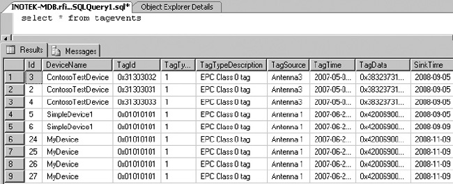
Figure 12-3. Selecting the results in standard format
If you add a FOR XML AUTO directive to the select * from tagevents query, the results will be formatted in XML. With a little more effort, not only can the results be formatted, but the overall structure of the data can be improved. This can be shown by first selecting the results using the following statement, which results in the XML shown in Listing 12-3:
select top 1 (*) from tagevents FOR XML AUTO
Listing 12-3. Simple Single Result Formatted Using FOR XML AUTO
<tagevents

 Id="3"

 DeviceName="ContosoTestDevice"

 TagId="dbobject/tagevents[@Id='3']/@TagId"

 TagType="1"

 TagTypeDescription="EPC Class 0 tag"

 TagSource="Antenna3"

 TagTime="2007-05-04T04:48:54.433"

 TagData="dbobject/tagevents[@Id='3']/@TagData"

 SinkTime="2008-09-05T11:14:44.373"

 ProcessName="ContosoTestProcess"

 ExtData="[EDITED FOR CLARITY]"

 LogicalDeviceName="mylogicaldevice"

 TagIdAsHex="0x31303032"

 TagDataAsHex="0x383237313838303231303239"

/>
Using this approach forces each row in the table to be produced as an individual XML document. But what if all of the results should be treated as a single XML document? What if the structure of the document needs to be modified such that each of the devices has its information rolled up—for example, all of the ContosoTestDevice events are rolled up under a single ContosoTestDevice node? In this case, the structure of the XML can be explicitly defined, with the result matching that shown in Listing 12-4.
Listing 12-4. Restructuring the Query with Explicit Structure
select NULL

,(SELECT device.DeviceName As "@DeviceName"

  ,device.TagType As "@TagType"

  ,device.TagTypeDescription As "@TagTypeDesc"

  ,(SELECT Cast(tag.TagIdAsHex as varchar(100))

    FROM tagevents tag

    WHERE tag.devicename = device.devicename

    GROUP BY Cast(TagIdAsHex As varchar(100))

    FOR XML PATH('TagRead'), BINARY BASE64, TYPE

   )

  FROM tagevents device

  GROUP BY DeviceName

           ,TagType

           ,TagTypeDescription

  FOR XML PATH('Device'), BINARY BASE64, TYPE)

FOR XML PATH('ResultSet'), BINARY BASE64
The results of this query are shown in Listing 12-5.
Listing 12-5. Structured Result Formatted Using FOR XML PATH
<ResultSet>

 <Device DeviceName="ContosoTestDevice"

         TagType="1"

         TagTypeDesc="EPC Class 0 tag">

  <TagRead>0x31303031</TagRead>

  <TagRead>0x31303032</TagRead>

  <TagRead>0x31303033</TagRead>

 </Device>

 <Device DeviceName="MyDevice"

         TagType="1"

         TagTypeDesc="EPC Class 0 tag">

  <TagRead>0x01010101</TagRead>

 </Device>

 <Device DeviceName="SimpleDevice1"

         TagType="1"

         TagTypeDesc="EPC Class 0 tag">

  <TagRead>0x01010101</TagRead>

 </Device>

</ResultSet>
Discussion
Learning to incorporate XML into your BizTalk RFID solutions will greatly improve the overall design and ease of development. Become familiar with the syntax of XQuery and FOR XML directives so that data can be structured in the way it is most appropriately presented to the external world.
12.3. Debugging Tips
Problem
I have a number of different components in my BizTalk RFID infrastructure, including .NET assemblies, web services, enterprise applications, database calls, and log files. I am at the development stage, and am struggling with a cohesive way in which to debug and track what is occurring as different components execute.
Solution
Debugging different components in an integrated environment requires varying approaches. To demonstrate a process of debugging across such an environment, this discussion will look at several components that make up a typical “integrated solution.”
Debugging Event Handlers
The process of debugging an event handler is quite simple; it requires attaching to the RFID service using Visual Studio. Once an event handler has been successfully built in Visual Studio, open the Debug menu and select Attach to Process. Select the RfidServices.exe process and click OK (as shown in Figure 12-4). Set appropriate breakpoints in the event handler code. When a BizTalk RFID process executes and initiates the event handler, this code will run and the breakpoints will enable the developer to step through the code.
![]() Note Make sure that the event handler assembly has been deployed to the proper location prior to attaching to the process. If the assembly has not been deployed and is not referenced in a BizTalk RFID process, the event handler code in Visual Studio will never execute.
Note Make sure that the event handler assembly has been deployed to the proper location prior to attaching to the process. If the assembly has not been deployed and is not referenced in a BizTalk RFID process, the event handler code in Visual Studio will never execute.
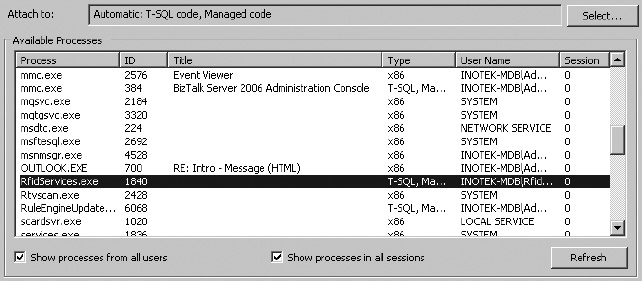
Figure 12-4. Attaching to the RfidServices process
Debugging Orchestrations
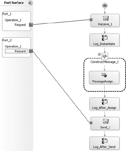
There are two options to debugging orchestrations. Unfortunately, there is nothing as simple as attaching to a process. Instead, a developer can either add “logging” shapes to an orchestration or use the Orchestration Debugger. The first option is as simple as placing an expression shape in an orchestration and adding logic to write to the Windows Event Viewer (or alternative logging options). The second option requires that the orchestration be fully deployed and that the Orchestration Debugger be accessed using Health and Activity Tracking (HAT).
To add simple logging using expression shapes in the orchestration, take these steps:
- Add an expression shape to the orchestration wherever logging should take place. As shown in Figure 12-5, a number of expression shapes have been added simply to log information as steps in the orchestration are performed.
- Add code to each expression shape to log to the event viewer, such as that shown in Figure 12-6.
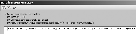
Figure 12-6. Logging to the Windows Event Viewer from an expression shape
The Orchestration Debugger is available through HAT, and is occasionally useful (though somewhat cumbersome to use). It requires that an instance of the orchestration be run before configuring a breakpoint in it. Take the following steps to use this tool:
- Open HAT. From the menu at the top of the application, click Queries. Run one of the queries, which will return an orchestration instance that has executed in the past (an example of a result is shown in Figure 12-7). Right-click the instance and select Orchestration Debugger.
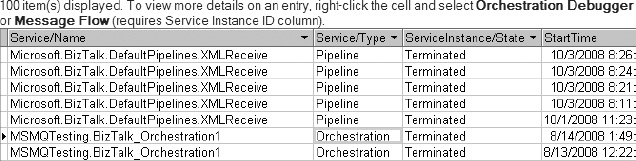
Figure 12-7. HAT query results showing terminated service (orchestration) instances
- When the debugger has opened, breakpoints can be set, as shown in Figure 12-8.
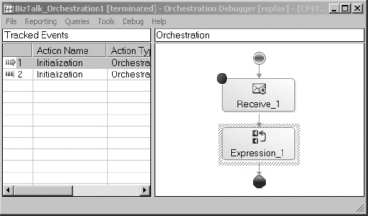
Figure 12-8. Setting breakpoints in the debugger
The next time that an orchestration instance runs, the breakpoints will be encountered. The instance can be accessed through HAT (the state of the instance will show In Breakpoint). Values associated with different parameters and messages within the orchestration will be accessible through the debugger.
Debugging Web Services and Web Parts
Debugging web services, SharePoint web parts, and anything else that executes under the ASP.NET service account is as simple as attaching to the appropriate service in Visual Studio. To do this, open the web service project in Visual Studio and click the Debug menu. Select Attach to Process, and click the appropriate process (generally w3wp.exe for SharePoint and aspnet_wp.exe for web services, though these may change depending on environments). Set breakpoints within the Visual Studio project and force the code to execute (either by running SharePoint from Internet Explorer or consuming the web service from a .NET application or other source). An example of attaching to the w3wp.exe process is shown in Figure 12-9.
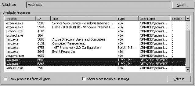
Figure 12-9. Attaching to the w3wp process to debug a SharePoint web part
Discussion
Debugging in an integrated environment can be somewhat overwhelming when first initiated—but breaking down the integrated components into the constituent parts leads to a much more focused and simplified experience. There is no single, universal way to debug components, but there is a similarity in the way most .NET applications function.
12.4. Integration with BizTalk EDI Functionality
Problem
I want to trigger the creation of an EDI document from BizTalk Server when certain RFID events are fired. I understand the basic interaction between BizTalk RFID and BizTalk Server, but I don’t understand how to integrate the BizTalk Server EDI components.
Solution
A common scenario for triggering EDI documents from RFID readings is to send advance shipping notifications (EDI document type 856). For example, when a case of products is scanned by an RFID reader as it is loaded onto a truck for shipment, you may want to immediately send an 856 to the appropriate trading partner. The process for sending an EDI document starts with publishing the appropriate information in BizTalk RFID to BizTalk Server. Once the data is in BizTalk Server, the EDI components are used to format and route the document to the appropriate destination. To demonstrate how to configure each of the components, we’ll discuss the architecture outlined in Figure 12-10.
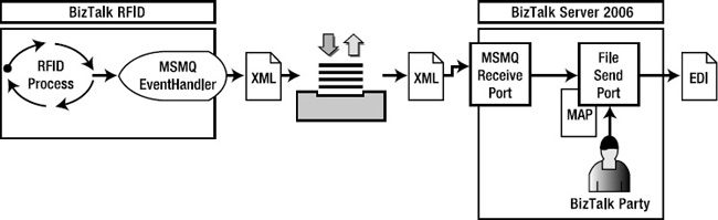
Figure 12-10. RFID-to-EDI document component architecture
Preparing the Foundation
Chapter 8 presented an extensive outline of how BizTalk RFID and BizTalk Server can communicate with one another. Rather than rehash this discussion, we will start from the point of handoff to an MSMQ—where a BizTalk RFID event handler places an XML document on the MSMQ and BizTalk Server receives the data using an MSMQ receive port. The following components need to be in place for the flow of information from BizTalk RFID to BizTalk Server to take place:
- The BizTalk RFID event handler that pushes information to the MSMQ. See Exercise 8-1 for details on publishing to an MSMQ.
- BizTalk Server, set up to receive data from the MSMQ using a receive port. See Exercise 8-2 for details on subscribing to an MSMQ.
Assuming these steps have been taken based on the exercises from Chapter 8, the information that will be posted to BizTalk Server will look similar to Figure 12-11.
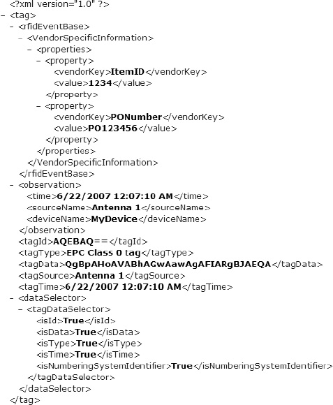
Figure 12-11. Sample output XML
With the send port successfully writing out the XML that was posted to the MSMQ, the solution is now ready to be built upon to include the EDI components. This will require taking the following steps:
- Add an XSD schema that represents the incoming RFID XML and modify the XML receive pipeline.
- Create the map that transforms the data from the RFID XML to the EDI representation of an 856 document.
- Configure a BizTalk party to represent the target trading partner.
- Prepare the send port to use the
EDISendpipeline, the newly created map, and the configured trading partner properties.
Preparing the Receive Port
The first step is to create a schema that matches the RFID XML on the MSMQ—currently the data is simply passing through the receive and send ports, since both are using the default PassThru pipelines. A schema can be created by using the XML that is output by the send port (shown in Figure 12-11) using the Add Generated Items wizard (see Recipe 12.5 for more details). A schema that represents this data is shown in Figure 12-12. Once the schema has been created and deployed, the receive port must have its PassThruReceive pipeline changed to XMLReceive.
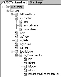
Figure 12-12. XSD generated from the RFID XML
Creating the Map
The second step is to perform the transformation of the source RFID XML into the target EDI 856. This will require three BizTalk artifacts:
The source schema: This was created in the previous section—it is the
RFIDTagRead.xsdschema.The target schema: This is the EDI 856 schema. When the BizTalk EDI components are installed, a directory is created that contains thousands of EDI-related schemas. In the case of the 856, it is included in the
X12folder.
![]() Note For purposes of this discussion, the 862 document that will be used will be the 4010 version, which is located in
Note For purposes of this discussion, the 862 document that will be used will be the 4010 version, which is located in $:Program FilesMicrosoft BizTalk ServerXSD_SchemaEDIX12�0401.
The map: This is the actual map the defines the rules of data transformation between the source and target schemas.
Using Visual Studio, create a project with both the source and target schemas, and a new custom map. The mapping rules should be based on the EDI implementation guide provided by the trading partner. This discussion won’t go into detail about how to perform the mapping, aside from showing the key elements in the source schema mapped to the target. Information that is not available in the source schema will need to be gathered through database lookups, .NET assembly callouts, functoid configurations, or other means available through the BizTalk mapper.
An example of mapping the purchase order number to the target 856 is shown in Figure 12-13. The functoid combination states that if the vendorKey element in the source document is equal to PONumber, then map the value element to the PRF01 node. Since there are multiple property nodes on the source document, a loop functoid is added to ensure all of the source values are worked through.
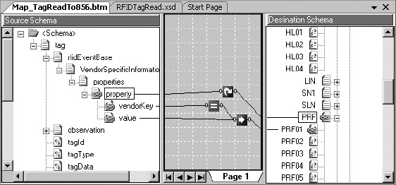
Figure 12-13. Create the map to create the 856.
Once the full mapping has been completed, deploy the source, target, and map so that they are accessible in the BizTalk Administration Console. The map will eventually be added to the send port that is associated with the target trading party.
Configuring a BizTalk Party
The next step is to configure a BizTalk party with the information needed to correctly create the envelope of the EDI document. The mapping of the 856 leads to the body of the document being created—but no envelope information is added until the information is sent through the EDISend pipeline. In the case of the 856, the envelope consists of the ISA, GS, and ST blocks at the start of the document, and the SE, GE, and IEA segments at the end. For purposes of argument, assume that the document shown in Listing 12-6 is a valid instance of what is to be delivered to a trading partner. This figure shows the envelope information that will be configured in the BizTalk party.
Listing 12-6. A Valid 856 Envelope
ISA*00*          *00*          *01*001234567      *01*098765432

*081028*0603*U*00301*000007911*0*T*>~


GS*PD*001234567*098765432*20081028*0603*1390*T*004010~


ST*856*000001390~


...


...


SE*60*000001390~


GE*1*1390~


IEA*1*000007911~
Using this as a basis, the trading partner can be set up as a BizTalk party, with its EDI properties set to the appropriate envelope values. The basic steps to take are as follows:
- In the BizTalk Administration Console, right-click the Parties folder and create a new party. Give it the appropriate name and other general information. Know that these values are primarily for human-readable organization, and do not have an impact on how envelopes are routed. However, it is good practice to specify the correct information. An example of a party’s general information, based on the envelope’s ISA06 element (the target trading partner), is shown in Figure 12-14.
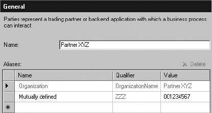
Figure 12-14. Sample of the party’s general information
- Once the party has been created, right-click it and select “EDI properties.” A window will open where all EDI envelope information is entered. Since the direction of information is flowing from BizTalk RFID through BizTalk Server to the trading partner, the values that will need to be configured are those related to Party as Interchange Receiver. The important values, shown in the
ISA,GS, andSTsegments in Listing 12-6, can be input directly into the property sheets. An example of this is shown in Figure 12-15.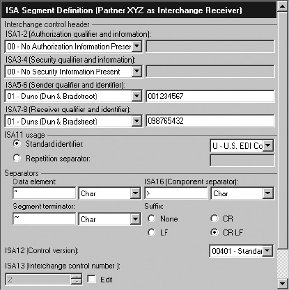
Setting Up the Send Port
With the party configured and the map and schemas deployed, the final step is to configure the send port. Begin by adding the new 856 map (created earlier in this discussion) to the send port. Next, change the send port’s pipeline to EDISend. After this, set the filter on the send port to subscribe to the receive port (BTS.ReceivePortName). Finally, tie the party to this send port by double-clicking the party and setting it on the Send Ports tab.
![]() Note There are a large number of options for configuring the send port’s filter. Using the
Note There are a large number of options for configuring the send port’s filter. Using the BTS. ReceivePortName is just one easy-to-implement option.
Discussion
This solution laid out the specific steps to setting up the EDI components of BizTalk Server to deliver an EDI document. It was intended to give an overview of the components, not to give an exhaustive look into BizTalk EDI. Some important topics to look further into are configuring acknowledgments (997s indicating that the 856 was received), EDI reporting (through the Group Hub page in the BizTalk Administration Console), and document tracking.
12.5. Creating an XSD Based on BizTalk RFID XML
Problem
I have an XML representation of RFID data that is ready to be posted to BizTalk Server. To successfully process this, I need to create an XSD. What is the simplest way to create this?
Solution
You can generate an XSD schema from an XML instance using a wizard available through Visual Studio, or using the XSD.exe tool. To create a schema using the wizard, follow these steps:
- Create a new BizTalk project in Visual Studio.
- Right-click the project and select Add Generated Items.
- In the Add Generated Items wizard that opens, select Generate Schemas, as shown in Figure 12-16.
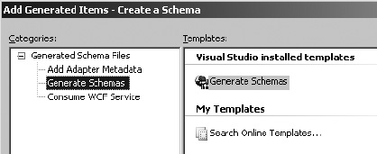
Figure 12-16. The Add Generated Items wizard
- On the next screen, select Well-Formed XML from the first drop-down, and select a valid instance of the XML to base the XML on in the second field (see Figure 12-17).
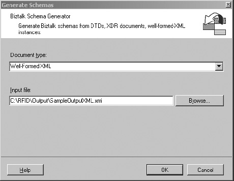
Figure 12-17. Selecting a well-formed XML document as the input
Note The first time this is performed, an error may pop up indicating that a script must be run before a schema based on a well-formed XML instance can be generated. Pay attention to this warning, as it states the exact location of the script that needs to be run (it is included in the installation of BizTalk Server).
- Click OK on the final screen, and a schema will be generated.
Discussion
The ability to create a schema from a well-formed instance is essential in facilitating communication between BizTalk RFID and BizTalk Server. There are two things you should note in the generation of a schema:
- The schema generation wizard will try to determine field types based on the input instance of the XML. Often, these are incorrect types, and need to be manually converted. For example, the item ID of an RFID read may be an integer value of
1234in one XML instance, andABCDin another. Both are valid, but since the schema was generated from the instance with1234in the node, the schema forces a field type ofxsd:integer—which is incorrect. The appropriate value should bexsd:string. Because of this, you must validate several instances against the schema that was generated prior to moving forward with using it.- The schema will be created with a name based on the input instance’s file name. Make sure to change this name to an appropriate value.
Conclusion
The goal of this chapter was to present a number of problems that are common when building out BizTalk RFID solutions. The recipes in this chapter introduced additional functionality across BizTalk Server, including handling different transport protocols, extending the communication with the underlying SQL database, and implementing EDI-based solutions. As you begin to work on your own implementations, the ability to architect a solid infrastructure that will meet the long-term needs of an organization is of critical importance. There are numerous ways to architect and implement a solution, but only experience and exposure to a variety of problems will ensure that the chosen architecture is the correct one. The key phases of a successful implementation always include the following:
Technical design and architecture: Integration projects always require extensive technical architecture. BizTalk Server implementations are generally 80 percent architecture and design, and 20 percent development and build.
Development: There are a large number of components and concepts to understand with BizTalk Server, but once these are fully realized, actual development time is generally very short in duration. There is a fairly substantial learning curve at first.
Testing and quality assurance: Test phases are always important, but when integrating enterprise systems and data, they are of even higher priority. The test phase must include business analysts and data owners, and should not be left solely to a developer.
Deployment: BizTalk deployments are generally quite easy, and include the ability to import and export MSI files and binding files. Building a staging environment that mimics production will facilitate a much easier transition to a live environment.
CASE STUDY: COUNTERING TERRORISM
Industry: State security.
Overview: A trial system was put into place in Germany to track and scan facial features using RFID technologies. Volunteers were asked to carry RFID tags with them as they commuted to work, where they passed by several camera systems. These camera systems would record the faces of the individuals carrying the RFID tags, and upload the data to a centralized server where analysis could be performed. The system would measure features—such as the jawbone—and compare them with photographs already on file. Metrics were created to prove the validity of the comparisons.
Results: The test results were deemed promising, but wide-scale deployment has not yet occurred. In a real-world deployment, RFID would likely not be part of the system. Its primary purpose in this test system was to ensure that only those individuals carrying the RFID tag would be recorded, allowing the public at large to pass by the camera systems without being recorded. In an actual implementation, all individuals passing by the camera systems would be recorded.