
Chapter 4: OTS Going Forward Toward Digital Twins
One of the main aims of writing this book was this chapter. I wanted to see the Operator Training Simulator (OTS) projects move to using the new technologies available to turn these systems into Digital Twins (DTs). In this chapter, we will see how this can be achieved. In addition, we will look into the use of cloud systems and how they can be used to deliver OTS systems.
This chapter will require previous knowledge of OTS system delivery along with some knowledge of Integrated Control and Safety System (ICSS) project delivery. Many ICSS suppliers have their own OTS teams to deliver these systems. Integrating these two system deliveries will benefit every stakeholder of these projects.
We will see how this can be achieved and the challenges that come with this model.
We'll cover the following main topics in this chapter:
- Reaching the promised land
- The cloud is the way forward
- 3D virtualization
Technical requirements
This chapter will go into some technical details of OTS systems and how they can be turned into DTs. A background in process engineering, control engineering, system engineering, and general control room operator training will be beneficial to get the most out of this chapter.
Reaching the promised land
I had a vision, years ago, that one day we would get to integrate OTS projects with ICSSs and make the most of this for suppliers and end users alike.
Finally, in the 21st century, we have reached the promised land and this is a reality, and correctly so, we can call OTS systems DTs.
Unfortunately, in the past, OTS projects and ICSS projects were almost always kept apart and run as two different projects. I have worked for three ICSS suppliers and all three did the same. There were many reasons for that, but the main one was that the OTS project budget was much smaller than the ICSS budget, let alone the full project. For example, a Floating Production Storage and Offloading (FPSO) project could cost a few billion dollars; an ICSS, tens of millions; and an OTS could cost a million dollars or even less. This made the OTS project much smaller in the full picture of the project.
In addition to that, in the past, OTSs generally, and process models especially, weren't as good and the benefits of the OTS system were not clear for management to see. And if the management included accountants, then they wanted to see benefits much sooner than, let's say, engineer managers.
These days, models are better. ICSS emulation has never been this good. Computers are cheaper, and engineering experience in building OTSs has grown exponentially in recent decades.
These days, we can deliver OTSs 6-12 months earlier than the actual first plant startup, so the training of operators can happen at a time when they are not hugely busy and, more importantly, are available. We will discuss this in detail in Chapter 5, OTS Training and Delivery, of this book.
Since ICSS emulation is basically the same as in the main ICSS, we can use the OTS as a second level of ICSS testing.
When there are thousands of Inputs/Outputs (IOs) in a project and large-scale control strategies – some simple and others complex – along with safety logic and many automatic sequences, there is no way that, in a few weeks of ICSS Factory Acceptance Testing (FAT), all these can be tested and all scenarios can be verified. How do you dynamically test automatic sequences in the ICSS FAT? Usually, this is done by forcing field IOs to be healthy at different steps of the sequence, but this might not be true if you are using a process model.
In many projects I have delivered, we would sit and wait for the pressure to be, say, 80 barg. It would get to 79.6 barg and the sequence would stay put and not move. Here, process and control engineers would put their heads together (in the process, pointing fingers at each other!), and finally would find a solution. Many times, the sequence was wrong and needed changing.
How do you pick that up in ICSS FAT?
This is one example. I could list many: if a check valve is in the wrong place, the pressure will never get to the required value; a minimum stop on a seawater cooling control valve being too big could cause the gas to cool and get too cold during startup.
Again, how do you pick those up in ICSS FAT?
One OTS I delivered was for a Combined Cycle Gas Turbine (CCGT) plant in Malaysia for Siemens in the early 90s and when we went through the issues log in the OTS, the ICSS engineer said "As if I am going through the ICSS log!" So, if we reported the ICSS issues we found on the OTS, wouldn't that have saved everyone time and money? I kept asking myself why?
But slowly I started seeing more end users trusting OTSs and starting to use them properly, but that really depended on the end user and their attitude toward the OTS.
Another simulator I derived, in the Kingdom of Saudi Arabia, was for Ethylene Oxide/Ethylene Glycol (EO/EG). We were doing the OTS FAT in a room attached to the plant control room at a time when they were doing the first startup of the plant. One of the startup engineers would come to the OTS room every now and then and give the simulator a bow as appreciation for the learning he got from the OTS. That specific plant did its first startup 1 month ahead of the planned startup.
Over the years I have integrated tens of process models into ICSS databases that have gone through FAT. In all the ICSSs integrated, I can say all of them had faults in them. But it varied from a small number – say, 100 or less, to a large number of issues – say, more than 400. Of course, these ICSS databases were different in size and complexity so we are not comparing them, but the common thing is, all of them had issues.
The issues varied in complexity:
- Simple, such as HMI graphics
- Medium – a control strategy not working
- Complex – a whole automatic sequence coded wrongly
Of course, we need to take the preceding classification with a pinch of salt. We could say a Human Machine Interface (HMI) mistake is simple, isn't it? I remember one HMI mistake was a button that was supposed to do a fuel changeover. This was a gas turbine that was connected to a compressor trip. Now, you could say this is a simple change, but the effect of it is of high importance.
That is why, when I logged ICSS issues found on the OTS, complexity, importance, and impact needed to be clearly stated.
I can list many examples of a simple mistake in an ICSS that would cause a big safety issue. So, the classification of impact is important here and needs to be reported as such to the engineering team.
All previous examples point to the importance of merging the OTS and ICSS projects into one and getting the most of both.
But how did we run projects in the past?
An OTS project would kick off a month after an ICSS project and the process model was built and tested with Model Acceptance Testing (MAT) so it was ready to integrate into the ICSS.
The aim was to finish MAT when the ICSS had just undergone FAT so we could start integrating the two together.
The ICSS would move to site installation while we were integrating the process model into the ICSS in an OTS framework. When we found issues with the ICSS, most of the time, it was too late to report them in a manner that could get the most benefit out of the OTS.
When finding software issues in a project, the earlier the better. The Systems Science Institute at IBM reported that it cost six and a half times more to fix a bug found during implementation than to fix one identified during design. According to IBM, fixing a bug during maintenance is 100 times costlier than in the design.
This is shown clearly in the following graph (the graph is from https://www.researchgate.net/figure/IBM-System-Science-Institute-Relative-Cost-of-Fixing-Defects_fig1_255965523):

Figure 4.1 – IBM's Systems Science Institute cost of bug fixing
In projects where OTS is used to test the ICSS early in the project, usually after the ICSS has gone through FAT, it is cost effective to fix issues before shipping the ICSS on site for final installation. But, sometimes, it is beneficial for ICSS suppliers to move bug fixing on site as it might be that the main project is on a fixed price and site work will be reimbursed at very high rates, so it is better to deliver the ICSS as fast as possible and move work on site. But this can be avoided if an open discussion between parties happens early in the project – in the end, both suppliers and end users want a successful project.
So, what is the model I am suggesting to achieve DTs in the 21st century? Let's start by building the model and getting ready to integrate it into the DT.
Model build
Figure 4.2 shows a flow chart of the model building process. The detail of the process is descried in the Chapter 3, OTS Project Execution and Best Practices.
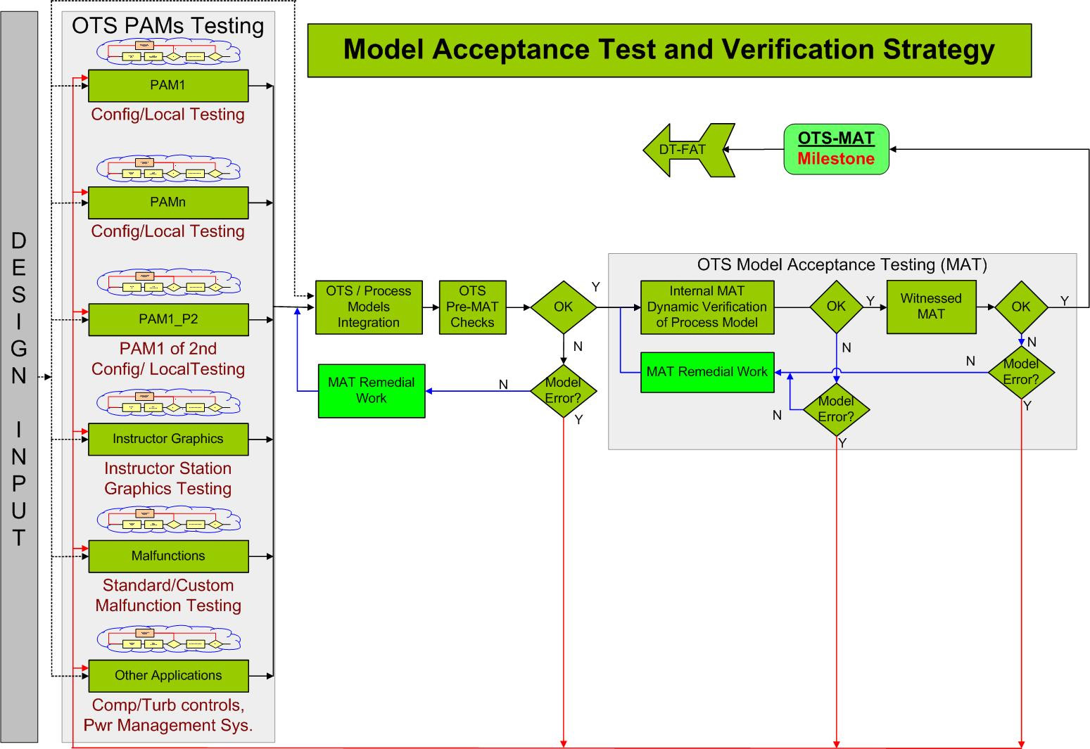
Figure 4.2 – Model acceptance test and verification strategy
Starting from the left we get the design input (Piping and Instrumentation Diagrams (P&IDs), Heat and Mass Balance (H&MB), and so on) as design input and will start building the different Process Area Models (PAMs). Every PAM is locally tested, and as best practice, peer-reviewed.
If there is more than one process modeling package, then the same should happen with that in building its PAMs.
Every PAM could be witness tested by the end user, or these days, with the availability of video-conferencing, these can be tested using Cisco's WebEx, MS Skype for Business, and other similar software. This is not shown on the flow chart, to keep it simple. But these will be discussed in Chapter 3, OTS Project Execution and Best Practices
The instructor graphics are needed to drive the MAT, so its graphics need to be drawn during this phase and all its functionality as well, including standard and custom malfunction scenarios.
Finally, if there is any emulated logic needed for the MAT, such as compressor controls, then this needs to be completed in this phase of the project.
All the PAMs need to be integrated into one (or more than one) process model and a Model Acceptance Test Readiness (PreMAT) should be done by the supplier until the process model is ready for internal MAT.
Internal testing is followed by witness testing and when the process model passes the MAT, it is ready to be integrated into the DT.
ICSS build
Figure 4.3 outlines the build of the ICSS and the process of FAT it to get it ready for integration with the DT:
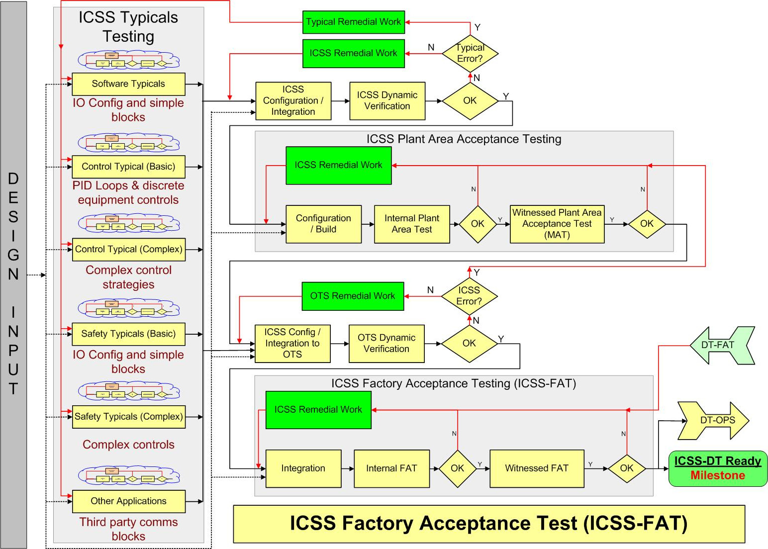
Figure 4.3 – ICSS FAT
Similar to the model build, the ICSS is built from smaller pieces and locally tested by the supplier.
The first area will be the IO configuration and getting the simple block configured and tested.
This will be followed by PID loops and discrete logic for equipment control.
The different areas will be built separately and could be built in parallel by different engineers.
More complex Process Automation System (PAS) logic is another area to be built. That will be locally tested as well. Different areas will interact with each other but when testing locally, these interactions will be fixed and will only be tested when all areas are integrated with each other.
Similar to the PAS, the Safety Instrumentation System (SIS) logic will be configured and tested. First the SIS IOs and then the SIS logic itself. The SIS itself will be divided into the plant areas and locally tested by the supplier.
Other third-party software that communicates with the ICSS can be left as an ICSS typical and tested as such. An example would be software such as Compressor Control Corporation (CCC), which is a good example of third-party software. This is usually tested in isolation and then integrated into the ICSS and a new test of the integrated software is carried out.
Similar, to PAM testing, every software typical can be witness tested either using available video conferencing software (this is not reflected on the flow chart, to keep it simple) or in-house testing.
All the typicals are integrated with each other and witness tested in a plant area-by-plant area process.
Now all these different plant areas can be integrated with each other, so the ICSS is ready for a witness test (FAT).
Before the witness test, the supplier usually does an internal test to iron out any issues.
When the ICSS has undergone FAT, the ICSS database is ready to be integrated into the DT. Even if the ICSS has been signed off as ready for DT integration, it is not ready for site installation and will only be signed off when tested in the DT environment, and this is the major difference from the previous delivery models.
Integration with the DT
Now that we have a process model that has passed its MAT and an ICSS that has undergone FAT, we can integrate the two and the result is a DT.
Figure 4.4 shows the flow chart of testing the DT:

Figure 4.4 – DT acceptance testing and training delivery
Now, in the DT, we are basically doing FAT on the OTS and the ICSS. At the end of the testing, the DT delivery milestone is basically the delivery of the OTS and the ICSS. The ICSS now can go for site installation and the DT will be passed to the operations department for training and engineering purposes.
Figure 4.5 shows all the pieces put together in one flow chart. It does look a little crowded, but since we explained the different pieces separately, I hope the full flow chart is not that difficult to follow.
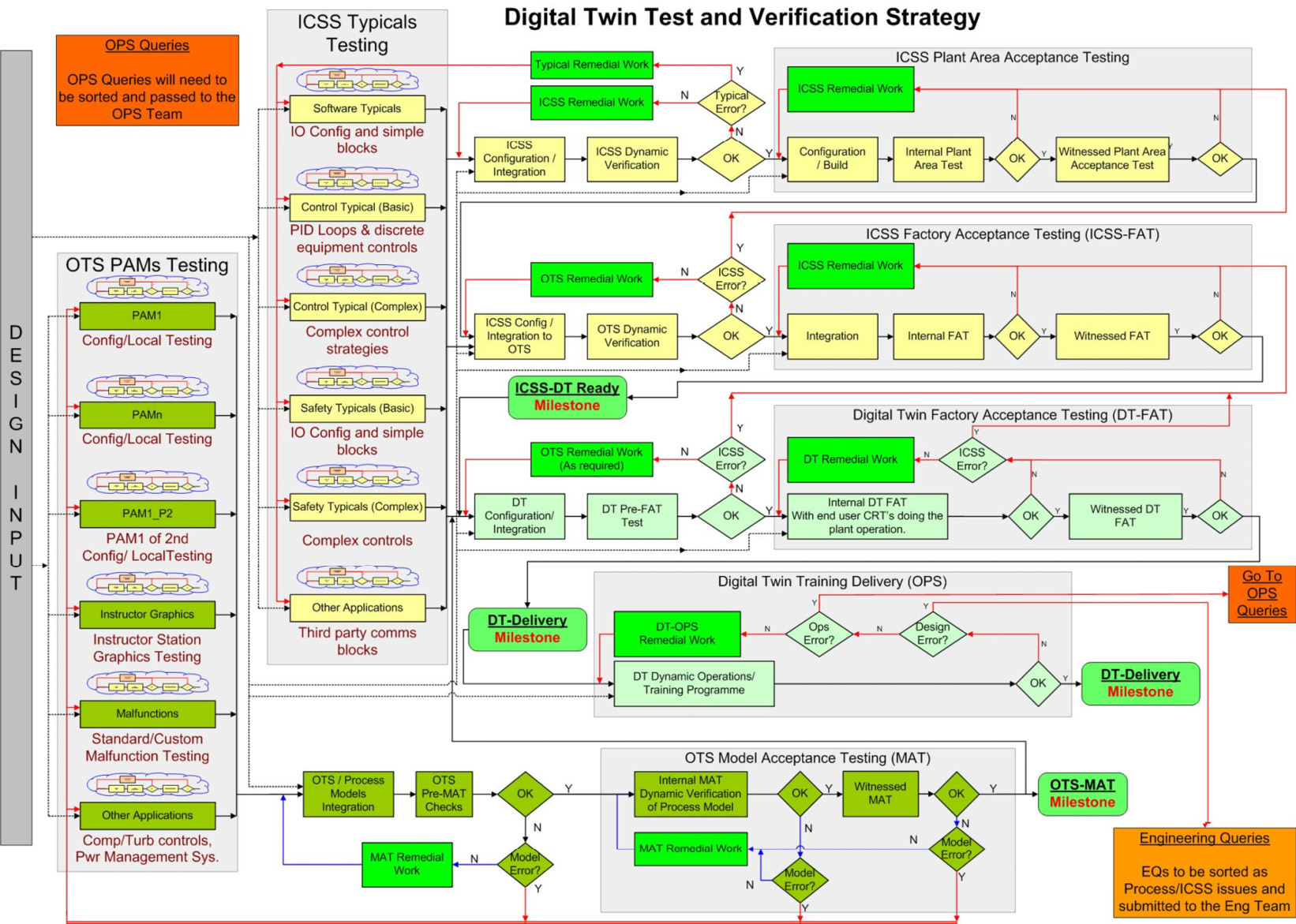
Figure 4.5 – DT test and validation strategy flow chart
So, you might ask, why should we use this model?
What are the benefits of using this model?
Is there an impact on the budget?
What about the delivery time? It seems the time needed to get the ICSS on site is prolonged?
I will try to answer these questions next.
The model to convert the OTS into a DT has its own benefits and challenges, which will be discussed next.
Benefits of the model
Here are the best benefits of using this model:
- A second level of testing the ICSS, which will reduce the number of defects to be addressed on site, where they will cost more.
- More importantly, the testing in the DT uses a dynamic model and hence full dynamic testing of the ICSS, which will address more issues in the ICSS.
- Both of the above will definitely reduce the ICSS commissioning time on site, saving a lot of time and money.
- The top two points will reduce the first startup time and will make the first startup much smoother compared to non-dynamic testing situations.
- All PID controllers will be tuned using a dynamic model, which will mean much less time on site trying to tune these controllers.
- A large part of the problematic issues in the process and ICSS will be highlighted in the dynamic testing and a mitigation plan will be drawn to address these on site. This will again save a lot of time and money.
- All third-party controllers (such as CCC® and MarkVIe®) will be tuned during the use of the DT, saving weeks of work on site.
- All the above will be done in a much less stressful environment in the office compared to work on site where work permits and limited access to equipment will make these procedures much longer.
- The ability to start HV motors many times in a DT – something you cannot do on site.
- I can share an example here of when I needed to start a High Voltage (HV) injection pump six times in an hour to find an issue in the ICSS coding. Finally, the code had one letter wrong. To find this on site would have taken many more hours, if not days.
- All automatic sequences will be dynamically tested and ready to go on site. This is a huge time saver as dynamic testing is the only way to prove these sequences.
- I can share another example here. On a project, we needed to run an automatic sequence 56 times until we found all the issues with it. It had process design issues as well as ICSS issues. This took a few days on the DT. Imagine how long that would have taken offshore where the site was.
- All the Control Room Technicians/Operators (CRT/CRO) will be trained on the most recent ICSS database, which will make them benefit from the training much more than training on a different version of the ICSS database
- Using a dynamically tested ICSS will for sure be safer. Some safety issues will be picked up during the testing.
- In a power plant simulator during ICSS testing on the DT, we found that the 260 MW steam turbine was going to engage the turning gear at very high speeds, which would have caused damage to the turbine and might have had an impact on the safety of personnel around the turbine at that time.
- While on another DT, the trip without blowdown was connected to the trip with blowdown. Imagine there was a fire and the operator needed to trip and hold (no blowdown) – the last thing you'd want to do is release more flammable gas into a fire area! But the button would have caused trip and blowdown, literally adding fuel to the fire!
Now that we have looked at the benefits of this model, let's see what challenges the model will bring.
Challenges
The main disadvantage would seem to be the prolonged ICSS FAT, which will cost extra time and money. But is it really a disadvantage? Let's address these concerns.
For time-related concerns, we can always ship the ICSS software that has undergone FAT to the site as soon as the FAT is finished. All the hardware and software (after FAT) can be installed on site. In parallel, we will be doing FAT on the DT and as soon as that is done, we only need to send the new ICSS database files to the site to be installed. This way, we will mitigate the risk of prolonged ICSS FAT. There will be an impact on the project schedule, but a small impact – it could be days or a couple of weeks at most – and this can be (and should be) planned into the project plan.
As for the financial concern, since we reduced the time impact to a week or two, the engineering cost to cover this will be limited, and if you compare it to the benefits you get with this model, it is definitely worth the cost.
The cloud is the way forward
Most OTS suppliers offer to place OTS on the cloud. This will have a huge advantage for both contractors and suppliers.
The use of virtual machines is becoming increasingly prevalent in the industry. As we have seen earlier, the footprint for an OTS could be an issue for many contractors, so could the suppliers solve this by putting everything on the cloud?
Of course they could! Instead of having an OTS with many servers, it can all be virtualized and put on a server on the cloud, leaving the contractor with fewer operator stations to connect to the virtual machines on the cloud.
Depending on the contractor's security policy, the cloud options are as follows:
- Private
- Public
- Hybrid
The private cloud option means having the servers on the contractor's side and this will be the highest security level. Another option is to have a third party such as Amazon or Microsoft host the virtual machines on their servers, which will be less secure, but a solution in between could be leaving the servers at the supplier's site – a hybrid solution.
OTS suppliers can offer a service to contractors to address the preceding challenges. Virtualized OTS can be placed on the cloud and users from any other place can access the system using a single desktop, laptop, or even an iPad to start using the full virtualized OTS system. In my last project, the OTS was virtualized and put on servers in Romania and we accessed the OTS from Aberdeen in Scotland.
By putting the OTS software on the cloud, the OTS suppliers will be offering the users all three known cloud services that this solution offers.
- Infrastructure as a service (IaaS)
- Platform as a service (PaaS)
- Software as a service (SaaS)
This solution, the cloud OTS, moves the infrastructure, platform, and software service away from the contractor and offers it as a service, paying for which could be (or will be) cheaper for the contractor than doing it themselves, with all the space and expertise needed only at certain times of the OTS use. The supplier can offer this service and help the contractor that way. Rather than the users having the OTS on their site and worrying about maintaining it, now they can rent it from the supplier through the cloud.
The supplier can offer a cloud service known as SaaS, which takes the maintenance and servicing of the system away from the contractor for an agreed fee. I think this will be the future and every OTS should consider this option.
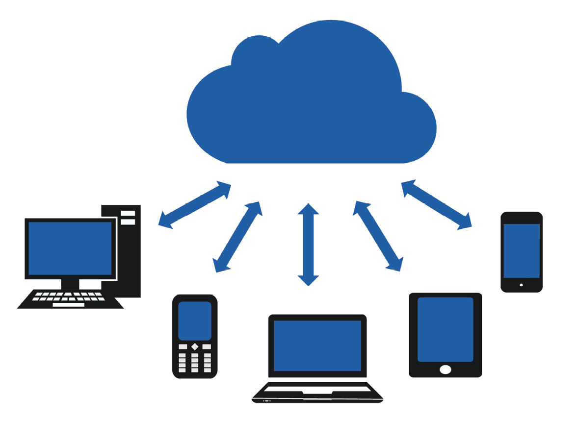
Figure 4.6 – Cloud OTS
Figure 4.6 (from https://www.pinclipart.com/maxpin/iiwRhwJ/) shows how the OTS can be placed on the cloud and contractors can access it using different types of devices.
Many suppliers offer this solution and I recently read that Neste Advanced Process Controller (NAPCON) offers this service. Have a read at https://www.napconsuite.com/napcon-cloud-ots-is-going-to-change-your-training/ if you are interested.
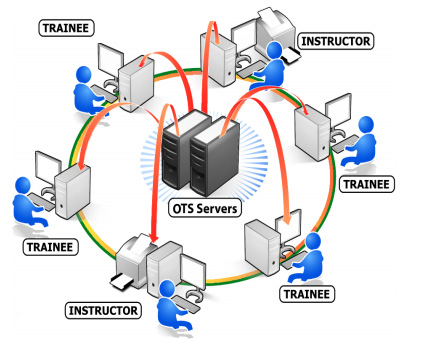
Figure 4.7 – Remote classroom on the cloud
NAPCON offers many OTS classes using models based on the cloud. Instructors and trainees can be located in different places but can access the systems and be trained using this solution.
Some of the NAPCON Cloud OTS attributes are as follows:
- Hosted on the public cloud
- Globally available
- Access from anywhere with any device
- Fully managed by NAPCON
- Cost-effective – pay for usage only
The following figure shows the NAPCON Cloud OTS general architecture.

Figure 4.8 – NAPCON Cloud OTS general architecture
NAPCON Cloud OTS can be accessed from anywhere in the world and with any browser.
It provides a classroom-like experience away from the classroom. For further information, please refer to www.napconsuite.com.
System security is a paramount issue that needs to be addressed to give users full confidence in systems, and companies such as NAPCON take it seriously.
Other companies offer Cloud OTS solutions. Another example is Yokogawa who offer the Cloud OTS solution. Yokogawa on their website https://www.yokogawa.com/library/resources/media-publications/simulate-to-accumulate/ say “The simulator [OTS] can be made more accessible and user friendly, helping to break the old-school conception of an OTS. This is where using 'the cloud' comes into play”
Corys is another company that offer the Cloud OTS solution by offering Cloud services to all OTS related solutions. Corys, https://www.corys.com/en/process-industries/solutions/ claim to offer low hardware cost, pay-per-use and easy access training solutions.
TSC Simulation specialize in OTS training delivery, they too offer the Cloud OTS solution.

Figure 4.9 – TSC Simulation Cloud SaaS model
TSC Simulation offer Software as a Service (SaaS) and explain how that works. For further detail please refer to their website https://www.tscsimulation.co.uk/solutions/classroom-simulation/cloud-delivery.
Aveva (https://www.aveva.com/) is another company that offers a cloud OTS solution. On its YouTube channel, it shows how it used the cloud OTS solution to the end user which was TOTAL OLEUM with cooperation with Microsoft using Azure https://www.youtube.com/watch?v=Kuc_h76CXTs.
We can see that many companies have started to offer these solutions on the market, and I can only see the demand for them increasing as the Covid-19 pandemic has shown the need for such solutions to be in place.
In the next section, we will look into another fairly new technology that offers another solution made available by technology advancements, which is 3D virtualization.
3D virtualization
In the last decade, we have seen 3D virtualization enter the market and all the main suppliers are offering it with their DT offering.
So, what is 3D virtualization and what is it used for?
Since every asset comes with some sort of 3D software model, suppliers can take these models and make all the outside (field) operations (manual valves, locally started pumps, fire buttons, and so on) accessible to a trainee wearing 3D goggles.
This way, all outside operators can be trained in a back office on how to access these points in the most effective way.
We hear all the stories from operators on how difficult it is to get to some outside operation points. But if you train the operators well before the first startup on these points, then that will be a big timesaver when you start running the plant.
I have seen some software that has built-in malfunctions so you can imitate a fire while a trainee is in the middle of their work so they learn the best way to evacuate safely or where the closest fire button is.
There is definitely big value here for the operations team, but of course, this will come at a cost, and again, as always, a balance will need to be struck between that and the Return On Investment (ROI). What are the risks versus benefits?
Suppliers are integrating these 3D models into DTs and making solutions much closer to reality.
Here are some links for you to check out a few suppliers and how they are doing it. You can watch some videos at these links that will make it easier to see how it works.
Emerson:
Go to https://www.emerson.com and search for Mimic Field 3D.
Aveva:
Bentley:
Go to https://www.bentley.com/en/products/product-line/digital-twins/itwinnovation and search for Digital Twins for the Process Industry.
https://www.tscsimulation.co.uk/solutions/virtual-environments/bespoke-3d-services
Corys:
https://www.corys.com/en/3d-immersive-training
Summary
In this chapter, we discussed how an OTS system can be correctly used as a digital twin. We looked at a model for building an OTS in order to achieve the final aim of a digital twin model.
We discussed how, in parallel, a process model is built while the ICSS is being developed. Both systems are built using the same design inputs.
The process model is tested in isolation (MAT) to make sure it is in a good condition to be integrated into the ICSS after it has undergone FAT. When the process model is integrated into one system, we showed how that can be used as a digital twin.
We discussed the benefits and the challenges that the model brings and we tried to address these separately.
In a later section, we discussed upcoming cloud technology and how it can help in addressing many challenges in digital twin delivery. Covid-19 brought some challenges to the industry and one answer is using cloud technology so personnel can access systems from home.
Finally, we discussed 3D virtualization and how it can help in training field operators in the process industry.
We mentioned some companies that are using the cloud and 3D technologies as references for you should you need them.
In the next chapter, we will go through training delivery using OTS systems.
Questions
- Can you convert an OTS system into a digital twin?
- What do you think are the correct steps to build a process digital twin?
- How can you use a digital twin in testing your ICSS system?
- How can you use digital twins in reporting issues with process design? What process would you use?
- How can the cloud help in using OTS?
- Can you see 3D visualization helping in training field operators?