
Chapter 3: OTS Project Execution and Best Practices
I have been delivering OTS systems for the past 30 years, working with many OTS suppliers, and in 2013 I started a consultancy business helping OTS end users get the most out of their systems.
In the 1970s and 1980s, when OTS systems were new to the process industry, suppliers running OTS projects were executing projects with Distributed Control Systems (DCSs) (Integrated Control and Safety Systems (ICSSs) as they're known these days) because either the companies building them were DCS companies, or the smaller companies building them were guided by the DCS manufacturer.
Since the two projects (OTS systems and DCSs/ICSSs) are different in nature, particularly their execution methods, different companies had their own (almost ad hoc) OTS project execution strategies.
In this chapter, we will discuss a model that has proven over my years of experience to be the best practice in the execution of such projects, namely the V-model.
The project execution is discussed in detail and will help you in your OTS project execution, from data collection to the Kick-Off Meeting (KOM), model building, and testing through model acceptance, factory acceptance, then site acceptance, and finally, training and warranty.
We are going to cover the following main topics in this chapter:
- V-model
- Making the decision to acquire an OTS
- The SOR
- Project decision and award
- KOM
- Typical agenda for the KOM
- Detailed design specification
- Functional design specification
- Documentation
- Model topology
- Instructor station
- ICSS controls
- Non-ICSS controls
- Model build
- Model acceptance test
- Integration with ICSS
- Factory acceptance test readiness
- Factory acceptance test
- Shipping and installation
- Site acceptance test
- Warranty
- System maintenance
- Train the trainer
V-model
Over the years (with some pain), the OTS building process has improved for many reasons. Mainly, OTS suppliers have gained experience and some standards have started to be developed so teams don't have to reinvent the wheel every time a new OTS project is executed. Computers becoming more powerful has improved the process for sure. The simulators started becoming more realistic and more reliable.
I have used the well-known V-model in the projects that I have delivered, and this has proven to be very successful. In this chapter, I will explain how this model works and how it can be adapted for OTS projects. For more information, please see the International Electrotechnical Commission (IEC) safety software standards 61508-3.
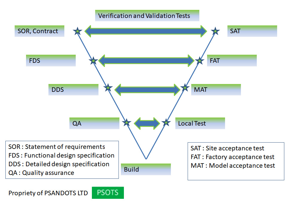
Figure 3.1 – Verification and validation process of OTS projects
The preceding diagram shows the V-model that I adapted to the OTS build process. The left leg of the V represents a set of written specifications in the project that will be tested in the project milestones on the right-hand side of the V. The tests in the middle of the V are the Verification and Validation (V&V) stage of the process.
Sometimes it seems difficult to draw the line between V&V. When is a process verification and when is it validation? I once read the following, and it stuck with me. It does make it easy to define the two processes:
- Validation is the answer to the question "Are we building the right system?"
- Verification is the answer to the question "Are we building the system right?"
What it comes down to is that validation is when we want to make sure that we are building the correct system as per the customers' requirements, and verification is making sure that we are building a sound engineering solution that is bug-free, easy to maintain, and based on sound engineering principles.
The V-model is an easy-to-follow step-by-step process. Starting at the top left of the V, the contract is the main starting point between the OTS supplier and the technical accepting authority, not necessarily the end user as sometimes Engineering Procurement Construction (EPC) do that role on behalf of the end users. From this point on, we will refer to the accepting authority, being the end user or EPC, as the customer. When the contract is set, it is usually be based on a Statement of Requirements (SOR) document that defines in detail the minimum technical requirements the OTS supplier should provide. Usually, but not always, the SOR will contain the financial and legal aspects of the contract.
The process will follow after the SOR is approved by all stakeholders and it is confirmed that the OTS will deliver at least the requirements in the SOR. Then the Functional Design Specification (FDS) is developed and agreed upon.
After this, a Detailed Design Specification (DDS) is developed. This document will detail the process model design and modeling standards.
The next step is the Quality Assurance (QA) procedures developed by the supplier to test the process model. These procedures need to be shared with the customer.
We have reached the bottom point of the V. Here, the supplier will build the model and get it ready to be tested internally, which is the Local Test point on the right-hand side of the V, against the QA procedures. The results of the test should be shared with the customer.
When the supplier is ready to conduct a Model Acceptance Test (MAT), the customer is called, and a MAT will be carried out to verify that the model has been built in accordance with the DDS.
After the MAT is completed, the supplier will integrate the model into the ICSS, and the next milestone will be the Factory Acceptance Test (FAT). The OTS is verified in the FAT against the FDS. The customer will be testing the OTS to make sure it delivers what the FDS has put in place.
The final step in the process is a Site Acceptance Test (SAT), where the OTS is validated against the SOR and the project contract. While this may seem to be a big testing task, it usually is not as the results of all previous tests will be taken into account. For example, the hardware delivered on the project will be checked, agreed, and accepted in the FAT, so in the SAT this hardware will go through a travel-well test only. But in the SAT, we have to make sure the system that we delivered is the correct system.
Every testing step will have its own testing specification document. The MAT, FAT, and SAT specification documents will need to be reviewed and approved by the customer.
In the next section, we will look into every step of the OTS life cycle and I'll give some examples of best practices that I have learned over many years of building and delivering OTSs.
Making the decision to acquire an OTS
In Chapter 1, OTS Introduction, when I talked about the different types of OTSs, I provided some case studies that will hopefully help in the selection of the type of simulator that the customer will need. But before making that decision, we need to consider some questions:
- What will I be using the OTS for?
- What is my budget?
I found that setting out the requirements for the OTS in a SOR document will help answer the first question. This will help the suppliers to come up with a price, which you will then need to compare to your answer to the second question.
The SOR will need to be drafted, but it will need inputs from all OTS stakeholders to arrive at the right balance between the OTS scope, the budget, and time available.
The legal side of the contract is not within the scope of this book; we will concentrate on the technical issues here.
The SOR
The SOR should be written when an OTS is needed. It should be given to the OTS supplier with clear statements that will help the supplier to come up with a clear technical offer and price for the OTS.
The SOR should define the scope of the OTS. The best way is to add the Piping and Instrumentation Diagrams (P&IDs) to the SOR so the OTS' scope is clear.
The SOR should include the scope of the control systems and the minimum hardware performance needed. The contractor should clearly state the KPIs that will make the project a success. This will help the supplier to come up with a solution that is fit for purpose.
What should be in the SOR, then? Please refer to Chapter 6, OTS Sample Documentation, to see an example of an SOR.
Project decision and award
When the SOR is completed, it can be given to OTS suppliers to come up with suggested solutions and prices. The supplier will have enough information to make a proposal. Usually, a round of questions and answers between the end user and supplier will take place to clarify unclear issues.
Due to budget limitations, sometimes the end user will reduce the scope of the OTS to get the best solution. But in this case, the end users will be running a risk because some of the budget should be put aside for future unseen variations, OTS updates, and so on.
Kick-off meeting
When the project is awarded, the first meeting between the stakeholders, end users, suppliers, and subcontractors will be at the KOM. Usually, this will take place at the OTS contractor's offices, where there is quick access to documentation such as P&IDs, Heat and Mass Balance (H&MB) reports, and so on. But it could be held at the supplier's offices if it is more convenient to all stakeholders.
The typical duration for this meeting is between 2 and 5 days. It depends on what is agreed to take place during this meeting and how big the OTS scope is. I prefer to do as much as possible in this meeting as this will help to kick-start a healthy OTS project.
A typical KOM agenda will be discussed next, providing details for every point. These details might not necessarily fit all projects, but they should fit most projects.
Typical agenda for the KOM
Typically, the following items will be on the KOM agenda:
- Introduction and project contacts
- KOM objectives
- Project overview
- Project organization
- Scope of work
- Schedule review
- Specification and design
- Test and acceptance
- Data collection
- Action list
- Meeting close
Now we will discuss every item in the preceding list in some detail.
Introductions and project contacts
The first stage is a round of introduction of all teams, the end user, the supplier, the EPC, and any other stakeholders. A clear table should be filled in so contact details are clear:

Table 3.1 – Sample OTS project contact table template
Usually, the preceding list is maintained by the supplier's lead engineer.
KOM objectives
At this point, the KOM objectives will be stated and agreed on. Of course, these objectives would have been communicated beforehand via email and at this point they will be confirmed and modified if needed.
As a minimum, by the end of a KOM we should have introduced all the stakeholders, discussed the project's objectives, schedule, and timings, agreed on data collection, and if possible, marked up the OTS scope on the P&IDs. Testing and acceptance criteria should be agreed as well.
All the financial aspects of the project should be discussed as well, including invoicing, change orders, and deliverables.
Usually, after the introductions, the meeting will split into two teams. One will discuss technical issues and the other financial issues. However, for small projects, this might not be the case.
Project overview
A brief history of the project should be provided to the team so everyone is on the same page. The deliverables from the contract will be listed and agreed.
Contract documents and T&Cs are referred to. Additionally, contract issues and payment schedules will be noted, and the invoicing format could be agreed upon here as well.
As discussed earlier, the financial aspects could be left to the non-technical part of the project team. However, everyone should know the basics, even the technical team.
Finally, quality plan requirements and change order procedures should be discussed and agreed on.
Project organization
Typical OTS project organization for the supplier, contractor, and EPC (if applicable) will be discussed in this section of the meeting.
All the project teams and their roles and responsibilities will be itemized in this part of the KOM.
Let's now see a sample project organization for all the OTS stakeholders.
Supplier
A typical organization of the supplier project team is shown in the following diagram:
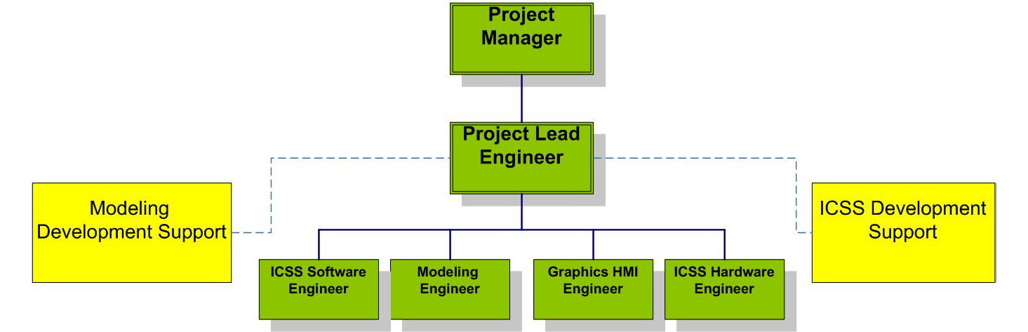
Figure 3.2 – Example supplier project organization diagram
Depending on the project's nature, the supplier's team could change. For example, if the supplier uses a subcontractor to perform the process modeling, then a new block for this subcontractor should be drawn, and they report to the supplier's lead engineer. Administration will be reported to the supplier's project manager.
Project manager
The project manager's roles and responsibilities will at least be as follows:
- Primary responsibility for the successful commercial execution of the project
- Sales handover and project initiation:
- Supplier sales and engineering interface
- Contract review
- Project team organization and definition of responsibilities
- End user and supplier interfaces
- Management of all contractual and commercial issues relating to the project:
- Implementation of project budget controls, such as purchasing, timesheet approval and expenses, and payment of invoices
- Completion and submission of change orders/waivers/concessions
- Monthly commercial reports
- Acting as the prime interface with clients in all areas:
- Focal point of contact for communication with customers:
- Progress reviews, action item lists, weekly calls, and monthly reports
- Commercial updates, variation orders, invoicing, and payment
- Ensuring conformance with project best practices:
- Project methodology and quality
- Risk and opportunity reviews (commercial side)
- Control of the project's schedule, including scheduling of resources, and purchasing equipment and material
- Maintenance of project deliverables list, such as documentation, training, hardware, software and licenses, and final delivery of application
- Management of hardware, such as purchase, staging, insurance, and shipment
- Management of third parties:
- Resource and equipment
- Licensors
- Project closeout:
- Administration
- Commercial
- Focal point of contact for communication with customers:
Depending on the size of the project, project managers usually run more than one project in parallel, hence many suppliers give the project lead engineer more responsibilities in the day-to-day running of the project, as we will see next.
Project lead engineer
The project lead engineer's main role is to make sure the project is specified and technically built and delivered correctly. Usually, the lead engineer is an experienced OTS modeling engineer, has delivered OTS projects in the past, and has seen the full project life cycle. This role needs expertise in many areas other than process simulation. They need to have experience in process safety and control, process operations, and software integration to name a few.
Now we will see what the roles and responsibilities of a lead engineer will typically be:
- They are primarily responsible for building and implementing a successful technical solution:
- They ensure the technical integrity of a viable technical solution.
- They ensure the solution is in line with contract requirements/functional specifications.
- They deliver technical status reports to the project manager. They contribute to monthly reports (activities completed, in progress, concerns, hours, and schedule/resource requirements).
- They lead the engineering team, with the following responsibilities:
- Data management on the project, confirming data freeze.
- Coordination with simulation, integration, and other team engineers to verify the quality of the application.
- Organize with development for required enhancement and bug fixes.
- Assign work responsibilities to team members (modeling engineers, integration, third parties, and specialists).
- Guidance for the engineering team on functionality.
- Ensure the integrity of the technical solution.
- Prepare modeling standards for the project.
- Organize project documentation for delivery.
- They prepare and lead monthly technical reviews. Technical reviews are usually a monthly meeting that the lead engineer will lead to manage the technical progress on the project. In smaller projects, these could be bimonthly.
- They lead witness testing with the client, such as FATs and SATs.
- They validate the technical solution:
- Review all Technical Queries (TQs) generated by engineers and resolve them with the client.
- Prepare the FDS, system applicable standards, engineering standards/control/change control, design unification, and design validation.
- Conduct internal testing and confirm work package delivery to the project
- Prepare FAT and SAT documents.
- Lead FATs and SATs, documenting exceptions.
- Engineer and approve the deliverables.
- Participate in quality audits/reviews.
- They check the system:
- Maintain system software backups.
- Accept hardware into the project and maintain a hardware log.
When we talked about the V-model in this chapter, we said the V&V in the model answer two questions. Validation answers the question "Are we building the right system?", while verification answers the question "Are we building the system right?"
The project manager and the project lead engineer share responsibility for the V&V of the project, but validation is more under the auspices of the project manager, while verification is more under the auspices of the project lead engineer.
ICSS software engineer
Many suppliers train the project engineers (usually modeling or system engineers) to act as ICSS software engineers. I never like that as it always costs more time and money to do it this way rather than using specialized ICSS software engineers to have this expertise on the OTS project.
The main responsibilities for such engineers are as follows:
- Ensure ICSS software integrity:
- Ensures the correct ICSS software version is installed on the OTS
- Ensures the correct software settings are installed on the OTS
- Ensures the correct users and domains are installed on the OTS with the correct credentials
- Act as a link between the OTS team and the main ICSS software engineers should any queries arise.
If the project decides to use project engineers (modeling or system engineers) to perform the role of ICSS engineer, then they will need to be properly trained.
Modeling engineer
Modeling engineers are usually chemical engineers with a high level of understanding of thermodynamics and fluid mechanics to help them model a process using modeling software. Their responsibilities are as follows:
- The main responsibility is to model a Process Area Model (PAM) as per the instructions from the project lead engineer.
- They ensure the PAM is modeled as per the marked-up P&IDs, use of the datasheets for all modeled equipment by simulation engineers, and include the controls needed for the MAT in the process model.
- They ensure the modeling of any in-scope custom malfunctions are included in the PAM.
- They ensure the PAM is tested in shutdown and startup scenarios.
- They liaise with the graphics engineer to ensure all instructor graphical functionality is included.
- They ensure all integration points to other PAMs and to the ICSS are included in the PAM modeling.
Depending on the size of the project, the project lead engineer could perform a modeling engineer role as well as their main leading role. In a small project, this is quite common.
Graphics HMI engineer
To be able to drive Filed Operated Devices (FODs) such as manual valves, these are modeled on the instructor station and driven through the instructor Human-Machine Interface (HMI) graphics. This role is required when there are many instructor station graphics to be drawn. On small projects, usually the simulation engineer would perform this role:
- The main responsibility is to make sure the instructor graphics are drawn correctly and will satisfy the scope of the OTS.
- They work closely with the modeling engineer and the lead engineer to make sure of the following:
- All FODs are accessible from the instructor station.
- All generic malfunctions are easily accessible from the instructor station HMI graphics.
- All custom malfunctions are easily accessible from the instructor station HMI graphics.
- All other HMI-driven functionality, such as scenarios, trainee assessment functions, and so on, are accessible from the instructor station.
Many suppliers will use modeling engineers for this role. Every project engineer will do the graphics for the PAM that they are modeling. For example, we have a gas plant that has two compressor trains, and the engineer who is modeling the process train will be doing the graphics for that. If another engineer is modeling the process of drying the gas, then they will do the graphics for that area of the plant. If this is the case, it is quite important to use a standard way of drawing that needs to be defined at the beginning of the project.
In larger projects, there is usually a dedicated graphics engineer who does the HMI graphics for the whole project.
ICSS hardware engineer
The main responsibilities of the ICSS hardware engineer are as follows:
- Check ICSS hardware integrity:
- Ensure the correct hardware is ordered and installed for the OTS on the ICSS side.
- Ensure the correct safe usage of the project hardware.
- Act as a link between the OTS team and the main ICSS hardware engineers if any queries arise.
If the OTS supplier is the ICSS supplier as well, then they will preferably use the same engineers (or the same engineering team) to look after the ICSS and OTS. This has proven to be a very successful model.
If the OTS supplier is not the ICSS supplier, then they will usually have system engineers to perform these tasks and they will be trained to use the different ICSS systems.
Modeling development support
Modeling development support is the engineering team either developing or in contact with the developers of the modeling software. Every new project (or support for existing ones) brings new modeling challenges, and these challenges need to be reported to the modeling software development team for support. This team has the following responsibilities:
- Ensure the correct modeling software version is installed that is compatible with the ICSS emulation version.
- Answer any TQs raised by the OTS model building team.
- Develop new modeling solutions as they arise in new projects.
Model software development teams usually have a roadmap to develop the modeling software. Sometimes, a new issue in a project will find its way to development and there will be a queue for it to join. In many cases, that queue is long enough to outlast the project. In such cases, development should provide a workaround or a temporary solution until a proper fix can make its way to the software through the development roadmap. Unless the issue is critical and needs a quick fix, the issue will jump the queue and a software patch is issued.
ICSS development support
Every ICSS supplier supporting an OTS solution will have a development team to support the software. Like the modeling development team, new and existing projects will bring new challenges, and these challenges will need to be addressed by the development team:
- Ensure the correct ICSS software emulation version is installed and is compatible with the modeling software.
- Answer any TQs raised by the OTS integration team.
New ICSS software is usually released annually, so some critical issues could be fixed, but software patches are either bespoke for projects or in a general patch release. These are all managed through the ICSS development support engineer(s).
End user
The end user will need to set up a project organization to match the supplier's one to make sure of successful delivery of the project.
The end user's project team is usually smaller. It could be as small as 2 to 3 people, but one focal point will be the OTS consultant to make sure the link between the contractor's project team and the supplier's OTS team remains strong.

Figure 3.3 – Example end user project organization diagram
Figure 3.3 is a typical project structure for the end user, but some smaller projects, for example, get the OTS consultant/engineer to perform the project manager's role as well. Others will have training instructors from the operations team.
Project manager
The main responsibilities for the end user's project manager are as follows:
- Primary responsibility for the successful commercial delivery of the project
- Management of all contractual and commercial issues relating to the project
- Control of project schedule
- Maintenance of project deliverables list
- Project closeout
As was previously mentioned, it's not necessary for the project manager role to be performed by a dedicated project manager on the project. In many projects, the end user's project consultant (OTS consultant/engineer) performs the project manager's duties on the project. Only in large projects is a dedicated project manager required.
OTS consultant
An OTS consultant on the end user's project organization will be responsible for the following:
- Primary responsibility for the successful technical delivery of the project.
- Be the point of contact for all OTS systems and optimization issues, including the following:
- Define requirements with the OTS supplier for the development of OTS packages
- Support the OTS supplier in the development of the OTS.
- Liaise with the project discipline engineers (process, mechanical, and instrumentation control engineers), operations, and contractor discipline engineers to deliver the OTS for operator training, engineering checkout, and operations support.
- Support end user and OTS supplier assurance processes (engineering reviews, and so on).
- Review and approve key contractor and supplier design documents.
- Witness all OTS acceptance tests, such as MATs, FATs, and SATs, and any other agreed tests.
- Support project planning, execution, and commissioning activities.
- Provide coordination where required between the OTS and the discipline engineer.
- Support the training instructor in developing the training strategy and training plans.
- Technically help maintain the OTS during training and engineering use.
- Review and approve all OTS documentation.
Not every project has an experienced OTS consultant. In such projects, it is proven that having a dedicated, experienced OTS consultant will be very beneficial. It will help in the production of a technically sound solution that is fit for purpose, and ensure a good balance is struck between the investment and the scope of the OTS.
Training instructor
One of the main uses of the OTS is training. Having a training instructor on the project will help in defining the correct and relevant scope of the OTS, leading to a successful training program. These are the training instructor's main responsibilities:
- Primarily responsible for the successful delivery of the project's training program.
- Develop, with the help of the OTS consultant and the operations team, the project's training philosophy.
- Develop the training plan for the project based on the project's training philosophy.
- Work closely with the operations team and the OTS consultant to define the training schedule.
- Work closely with the OTS consultant to help with the following:
- Define the scope of the SOR.
- Define the custom malfunctions.
- Define the instructor station scope of work.
- Act as an operator during all OTS tests, such as the MAT, FAT, SAT, and any other agreed tests.
- Support the project in any engineering tests that will need operations expertise.
- Review the supplier's OTS documentation.
An experienced training instructor will help plan the training well before the delivery of the OTS. Chapter 5, OTS Training and Delivery, will discuss training issues in detail, and we will see the effectiveness of having a training instructor on the project right from the word go.
Document controller
Ensure all OTS project documents are using the project standards. Every organization will use different software tools for document control, such as Sharecat (https://www3.sharecat.com/) and Coreworx (https://www.coreworx.com/). The document controller will be responsible for making sure all documents are using the correct version numbers, templates, and so on.
ICSS control engineer
Interact with the OTS consultant to answer any ICSS TQs from the OTS team. Usually, the ICSS control engineer will be part of the main ICSS project and will be aware of all aspects of the process control and safety in the project, or will have access to resources with expertise to answer TQs.
The ICSS control engineer's role, in addition to answering TQs, is to assess all OTS findings in collaboration with the OTS consultant to prioritize issues.
Process engineer
The process engineer interacts with the OTS consultant to answer any process TQs from the OTS team. Similar to the ICSS control engineer role, the process engineer should be aware of all the process design aspects and be able to answer TQs that come from the OTS team via the OTS consultant, or they should have access to resources that can answer the TQs. The process engineer will act as a link between the OTS team and the project in passing on the OTS findings. Some findings will need to be acted on immediately, such as a process safety issue found using the OTS; this cannot wait and will need to be actioned immediately. The process engineer and the OTS consultant will be putting all OTS findings to the project team via the process engineer.
Other third-party controls
This role is carried out by an engineer who is familiar with all third-party controls on the project. This engineer usually is the ICSS lead engineer on the project or an engineer that reports to the ICSS lead engineer. The third-party control engineer will interact with the OTS consultant to answer any third-party control TQs by the OTS team. Usually, this is covered by the ICSS control engineer. There's no need for special expertise for this, except in some special cases. For example, if the project is using CCC® or GE Mark VIe ® for compressor or gas turbine controls, they can be covered by the ICSS control engineer as they are widely used in the industry. This expertise is only required if bespoke third-party software is used.
Operations
The operations team in the end user's organization is one of the main stakeholders of the OTS. Its representation in the project is critical for a successful OTS project. Its responsibilities are as follows:
- Review and approve all training-related OTS documentation.
- Support the OTS consultant and the OTS instructor in providing all the data needed to build and run the OTS from the operation side.
- Make the trainees available for OTS training sessions.
Usually, the OTS is delivered to the operations team in the organization so they will be responsible for its day-to-day maintenance going forward.
Engineering procurement c
If there is an EPC in the project, then there will usually be one point of contact between the OTS supplier and the end user, and their responsibilities are as follows:
- Ensure the correct OTS delivery by the supplier as per the contract.
- Ensure the end user is supplying the required assistance to the OTS supplier.
- Ensure all commercial agreements are kept intact and payments are made on time.
- Witness all OTS tests.
Scope-of-work review
In this part of the KOM, all parties should agree and be clear on the scope of work. It should be agreed on what is in the scope and will be modeled in full detail with high fidelity. There are areas that will need to be modeled with less fidelity (medium to low), and they will be agreed on as well. A main process area is an example of a high-fidelity modeling area, while instrument air and nitrogen supply will be modeled with medium-fidelity modeling only.
There will be areas on the HMI graphics of the ICSS that will need to be populated with healthy (no-trip status) values at all times, such as vibration values of a compressor; these will be fixed at all times and hence only require low-fidelity modeling.
The best time to mark up the P&IDs is during the KOM. All the scope will be marked up and agreed. All three levels of modeling should be agreed.
I have to say the P&IDs will need to be carefully marked because sometimes, we mark some areas as medium fidelity, only for the supplier to find that these areas need to be more accurate when integrating the model to the ICSS. So, it would have been better to have marked these areas as high fidelity in the first place. Such areas will cause delays, waste, and loss down the line.
I like to make as much as possible high fidelity as this will pay us back later. Even if in the future, the end user wants to make changes to these areas in the ICSS, it will be much easier if they were modeled with higher fidelity to begin with.
As a best practice, all process areas will need to be marked on the P&IDs with a certain color (say green), and it should be agreed that all ICSS connections to these marked-up areas should be included in the model without needing to mark them up to reduce confusion.
The low-fidelity area should be marked with a different color (say blue), and fixed points should be put as notes on the relevant P&ID in yet another color (say brown).
In the main process area, you will need to model everything with high fidelity as this will be needed in operations and engineering studies further down the line. However, there are things that will not need to be modeled. Say that we have two Pressure Safety Valves (PSVs) and one is in operation and the other is on standby and with a manual valve that is normally closed. Modeling the latter is overkill. Of course, every project will have specific needs, but there are general rules that will apply to every project.
As mentioned previously, instrument air should be modeled as always available. You can add a malfunction of instrument air loss that can be activated from the instructor station to simulate instrument air not available.
Nitrogen supply should be treated in the same way as instrument air and should be available all the time with a malfunction if needed.
Fire and Gas (F&G) systems are another very important area in any asset, but do you really need to model all F&G detectors? What I have done in the past is model a few fire detectors that can be activated by a malfunction that could simulate a fire in one area of the asset. Similarly, a few gas detectors in one area will need to be modeled so we can train the operator (and supervisors) how to use overrides to F&G detectors. Gas detector malfunction will simulate a gas leak in one area of the asset. We can also include foam or fire water release scenarios that can be used to train personnel.
Fire water pumps starting and stopping should be modeled, and the fire ring should be pressurized when a pump is running. This is enough to train the operators on starting and stopping fire pumps.
Compressor and turbine vibration can be modeled as a fixed point, or simply a linear function of the speed of the compressor or turbine that is the best. Every transmitter should still be able to be malfunctioned through the generic malfunction capability of the instructor station.
Compressor seal gas systems can be modeled with medium fidelity and as per the requirements of the startup and shutdown of the asset.
Power supply systems can be modeled as available all the time. If we are using GTs to generate power and emergency or startup generators to generate emergency or startup power, then the best thing to do is to model the power matrix as a logical formula to say what drives (pumps, fans, and other electrical motors) are operational with the number of GTs/generators running.
When a GT is tripped, then a power-shedding formula should calculate which drives are to shut down first as per the project specification.
These are just some examples to help you with scoping the OTS, but again, every project will have its own needs. A system that we did not mention is the Heating, Ventilation, and Air Conditioning (HVAC) system; most projects I worked on with these systems were not in the scope of the OTS, but they can be treated the same as the F&G system and include a small sample to be used in training.
What we have discussed is the software side of the project. The hardware side will need to be agreed upon and confirmed in the KOM as well.
Schedule review
The OTS schedule should be agreed in the KOM, and all milestones should be highlighted and agreed.
A typical OTS milestone with some typical periods is as follows:

Figure 3.4 – Typical OTS project milestones
Of course, the size of the model depends on the nature of the project. For a Floating Production Storage and Offloading (FPSO) system, if the subsea is modeled and the marine and topside processes are all modeled, then the periods will be more than a gas platform where the subsea is not modeled. And for a refinery, for example, the time needed will be in between the FPSO and the gas platform.
Specification and design
In this section of the meeting, two main things will be agreed upon:
- Documentation, review, and approval cycle
The usual life cycle of documents is as follows:
- Rev A – Supplier internal review
- Rev B – Contractor to review
- Rev C – Ready for construction
- Every cycle will need 2 to 3 weeks to turn around, but almost always we find this is too long to handle in an OTS project. So, in the KOM, a process should be established and agreed to go forward. What should the supplier do if the documents are not returned on time? Questions need to be answered here:
- Agree on the participation of personnel in all project meetings, tests, and so on:
- Video conferences while building the FDS, PAM testing, and so on
- FDS and DDS approval meetings
- MAT
- FAT
- SAT
- Hold items that have been noted in the meeting to be listed as an action against appropriate team member to address going forward.
- Agree on the participation of personnel in all project meetings, tests, and so on:
The specification discussion will be followed by the test and acceptance discussion.
Test and acceptance
The main witnessed tests are the MAT, FAT, and SAT. In the KOM, all expectations for every test should be set and agreed. It is vitally important to agree on the pass criteria for every test and what document will be used to check against in our V-model of the software development:
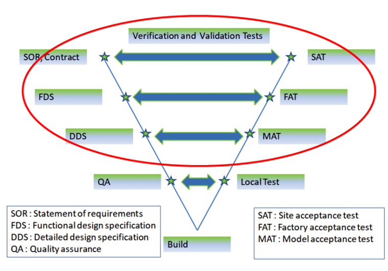
Figure 3.5 – OTS project test milestones
As you can see, the DDS is tested via the MAT, the FDS is tested via the FAT, and the contract or the SOR is tested via the SAT.
The DDS and FDS will be written and agreed upon a few weeks after the KOM, and that is long before the actual tests will take place. This will set the expectations for these tests, and surprises are expected during the witnessed tests.
In many projects that I have worked on, the FDS and the DDS are merged into one document ( the FDS); the DDS will be part of the FDS, which is fine, but which sections will be used in every MAT and FAT needs to be clarified. Usually, the DDS is needed when the requirements are non-standard and development is needed to satisfy these requirements.
When the FDS and DDS are reproved, the supplier will officially start building the simulation models. In reality, as soon as the KOM is over, the supplier will start building the simulation models to save time, but this is done at their own risk as the DDS and FDS are not finalized yet. It is a calculated risk, and the supplier will have many tasks that will need to be done anyway, and the risk is very small.
When each PAM is completed, it will be locally tested by the supplier's lead engineer using some QA procedures. When all the PAMs are completed, they will be integrated into the final model that will be MAT ready.
I have found that waiting for the first witnessed test at the time of the MAT is usually not a good idea. It is better to wait until every PAM is finished; then they can be shared with the contractor in an unofficial test, so the contractor can give feedback, which will be taken into account when the rest of the PAMs are built.
Doing it this way will save time and will be a win/win situation for the supplier and the contractor. While this was not easy to do in the past when the supplier and the contractor were based in different places, countries, and sometimes continents, these days, technology has made it very easy to do these tests using virtual meeting tools.
Data collection
Data collection is a major criterion for a successful OTS project. Every project will come with tons of data, especially these days, when megabytes and even terabytes of data can be stored easily on small USB disks.
To make this process successful, the end user contractor (or EPC if applicable) will need to sort the data and give it in a usable form to the supplier and, importantly, at a time when the supplier needs it.
In Chapter 6, OTS Sample Documentation, I give a sample data collection table and explain when it is needed in a typical OTS project.
Before the KOM, the supplier will need the Process Flow Diagrams (PFDs), H&MB, and P&IDs that should be enough for the KOM. As soon as the KOM is over, the contractor should start collecting the data required to build the model. Again, refer to Chapter 6, OTS Sample Documentation, for a more detailed list, but here is a summary:
- Datasheets for control valves
- Datasheets for heat exchangers
- Datasheets for pumps and fans
- Vessels datasheets
- Datasheets for transmitters
- Compressor/turbine datasheets
- ICSS HMI graphics files
This should be good enough to start building the model. The supplier will use these at different times of the model build process. As the model comes together, the supplier will need to put some controls in to be used in the MAT. If the ICSS is not available at the time then they will need control data to be used in the MAT, such as the following:
- Control philosophy document
- Interlock system description
- Cause and effect diagrams
- Trip and alarm schedule
- Startup and shutdown procedures
- Plant control data
- Compressor and turbine control philosophies
The challenging bit is sorting this data and putting it in a useful format for the supplier to use and most importantly make available to the OTS supplier in a timely manner. In Chapter 6, OTS Sample Documentation, there will be a typical timeframe as to when the OTS supplier will need the data. In almost all the projects that I have worked on, some data was not available when needed in the OTS building process. It needs to be agreed what should happen (in the KOM preferably) and what to do when data is not available and in every case of data being unavailable suggest a resolution; for example, when datasheets for isolation valves not available then use pipe size to determine the size of the valve.
An example of unavailable data is the startup and shutdown procedures, especially for a greenfield project. These will not be available early in the project. Usually, the OTS user will need the OTS available at least 6 months to a year before first oil/gas. The OTS build is started 1.5 to 2 years before the plant starts up, and most likely these procedures will not be available at that time when the OTS is being built. So, what do we do?
In the KOM, it should be agreed on what to do in these cases. For the preceding example, a typical process startup may be developed by the contractor and given to the user to use for OTS testing purposes.
Let's talk about the main data and how it should be handled in an OTS project.
Control valves
The process model will need three figures from the control valve datasheet to use, and they are as follows:
- The control valve flow Coefficient Value (CV)
- The control valve characteristics
- The actuator travel time
For the CV, you need to use the rated CV from the datasheet. If the CV is not provided, the best guess is the following table, which gives a good approximation for the CV from the pipe size. This table comes from the UniSim® manual:
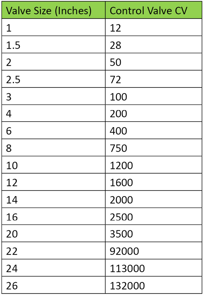
Table 3.2 – Typical CVs from the UniSim® manual
As for the second point, the CV characteristics, usually every piece of simulation software has some built-in characteristics in it, and the standard ones are linear, quick opening, and equal percentage.
The following diagram is from automationforum.in, and the full link is https://automationforum.in/t/control-valve-characteristics-trim/3062:
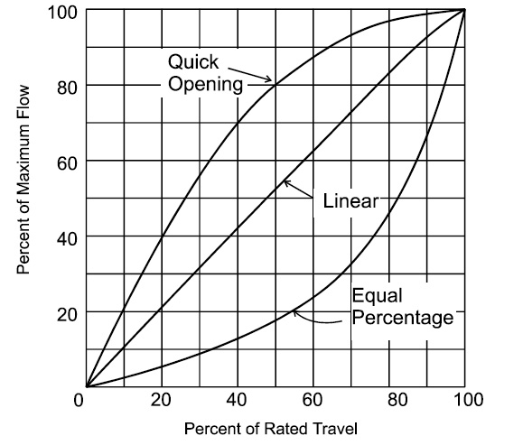
Figure 3.6 – Control valve characteristics from automationforum.in
But there are other types, such as very quick opening, modified equal percentage, and S curve. For these, the valve supplier should supply the corresponding characteristics curve.
What to do when such data is not available should be agreed by the OTS supplier and the contractor.
And finally, the actuator travel time should be taken from the datasheet, and if it is not available, it should be agreed upon to use the line size to estimate the travel time, for example, the number of seconds per inch of line size. Usually 1 second per inch is a good estimate.
Non-control valves
For all other valves (open/close), ESD valves, manual valves, and others, we will need the following information:
- CV data
- Actuator travel time
CV data should come from datasheets, but if it is not there then the valve manufacturer will have a catalog that will give a table of size, type (globe, butterfly, check, and so on), and their CV.
As for travel time, again this should be taken from the datasheets, but if it is not available then what I have done in the past is to use the ICSS database to figure it out. All automated valves will usually have an alarm in the ICSS if the actuator does not make their limits (valve does not open or close within the allowed travel time in the ICSS), and the travel time is usually the time taken for the valve to travel from fully closed position to fully open position plus some allowable time for signals to reach the ICSS from the field. So, you can always use that time plus the travel time in the OTS to be used as the valve travel time in the OTS model.
Pressure safety valves
For PSVs, the modeling software will need to know the following:
- The pressure set point that will make the PSV start lifting
- The pressure set point that will make the PSV fully open
- The size of the PSV
The data can be obtained from the datasheet, but usually, the set point and size are printed on the P&ID as well. The contractor should advise the OTS supplier that if the datasheet is not available, the data from the P&ID will be used.
Restriction orifice
The only data required for a Restriction Orifice (RO) by the modeling software is size. The size is taken from the datasheet.
Centrifugal pumps
A full set of datasheets for the pump and its drive are required by the modeling software, and the minimum data required is as follows:
- Pump capacity
- Head versus flow curves
- Efficiency versus flow curves
- Power versus flow curves
- Motor torque versus speed curves
If the datasheets are not available, then usually the operating point is known and the modeling software creates a default curve for the pump. But then a lot of dynamic modeling behavior will be lost, and this will need to be carefully discussed by the OTS supplier and the contractor.
Positive displacement pumps
Positive displacement pumps are usually used in less accurately modeled areas, such as chemical injection. By providing the duty flow, suction, and discharge pressures, the modeling software data entry for these pumps is fulfilled.
Centrifugal compressors
Centrifugal compressors are much more input data-hungry than the modeling software as they are much more complicated pieces of equipment. The typical data needed is as follows:
- Compressor capacity
- Head versus flow curves
- Efficiency versus flow curves
- Power versus flow curves
- Motor torque versus speed curves
- Compressor inertia
- Startup and shutdown compressor description
- Anti-surge control philosophy
- Compressor control philosophy
Every OTS project will have to decide what to do with compressor controls: are they emulated using the compressor supplier's software, or are the controls simplified in the modeling software?
In any case, usually in the MAT, the controls used are simplified in the modeling software, hence the control philosophy data requirement. If this data is not available, it will create a huge hole in the dynamic testing of the compressor in the MAT. This will be shifted to the FAT, where the emulation software has to be used, but in this case, you will lose precious time in finding issues with the model at the time of the MAT and not push them to the FAT.
If the controls are to be simplified in the modeling software, then a detailed testing scheme will need to be drawn up to validate the controls of the compressor to make sure it is as close as possible to the actual controls.
I always prefer the proper solution of emulation of the compressor controls using the supplier's software. Yes, it is more expensive, but it will pay dividends when it is used to help in commissioning the compressor. If you can use the simulator to avoid one compressor trip, then that will pay for the emulation.
I have delivered many projects with the controls in the modeling software, and in every project, the contractor said, "I wish we acquired the emulation software." And in other cases, I convinced the contractor to acquire the emulation software and at the project's conclusion, I was always thanked for encouraging the contractor to purchase the software.
Screw compressors
For screw compressors, a capacity datasheet needs to be used in the modeling software.
Heat exchangers
As shell and tube heat exchangers are the types of heat exchangers used the most, I will use them as examples here for the data required for modeling these exchangers. The datasheet will provide the following data for the modeling software:
- Heat exchanger type
- Overall heat transfer area
- Reference flow for the shell
- Reference flow for the tube
- Allowed pressure drop for the shell
- Allowed pressure drop for the tube
- Overall heat transfer coefficient (U) * heat transfer area (A), UA value or heat transfer rate
- Number of tubes per shell
For full dynamic modeling behavior as a minimum, the preceding examples are required by the modeling software.
Electric heaters
For electric heaters, the power of the heater is needed by the modeling software. Usually, they are modeled as on/off devices: when the heater is on it will provide the heating power required and when it is off, the power provided is zero.
If there is control over the power output, then when the heater is turned on with the controller at the minimum setting, the heater will provide minimum power and then it follows the controller output.
Vessels
Vessels will need, at a minimum, the following data:
- Vessel type
- Vessel dimensions
- Weir dimensions
- Instrument nozzle locations
It is important to get the datasheets, P&IDs, and vessel construction drawings. The latter are helpful for defining the exact positions for level taping, for example.
Columns
Columns will service different process issues, and some will need more detailed information than others, but at a minimum, the following data is required:
- Column type
- Column dimensions
- Weir dimensions
- Instrument nozzle locations
- Process description of the column operation
Similarly to vessels, it is important to get the datasheets, P&IDs, and vessel construction drawings.
General data
The data here helps the OTS supplier model the process as dynamically and correctly as possible.
Let's start with the Emergency Shutdown Cause and Effect (ESD C&E) diagrams. These will help the OTS supplier to understand the theory behind ESD trips, and in the modeling process, the supplier can discover whether some trip set points need to be re-visited as they can either make them more strict, if the dynamic testing suggests so, or relax them a bit to improve the plant performance.
Plant startup procedures will help the supplier a great deal as they can use them to locally test their PAMs as they build them to make sure they are modeled dynamically and correctly. However, they are not always available early on in a greenfield project.
Every modeled piece of equipment will need to have a reference elevation so static pressure is calculated by the model properly. One way is to give the OTS supplier the 3D drawings, but it will take the supplier forever to go through them, and they will not have the time. So, if there is any way to provide accurate equipment elevation to the supplier, that will help a lot.
A process description and control strategies document will be a gift from heaven to the OTS supplier. They will need it to model the basic controls in the model for the MAT if the ICSS is not available but they still want to perform plant operations in the witnessed test.
In general, the end user will need an OTS engineer who can liaise with the process and control engineers to provide the required data in a usable format to the supplier. Some may ask why the OTS suppliers do this, since the contractor is paying them to do so? My reply is they don't know the data as well as the project engineers, and if you give tons of data to the OTS supplier, it will take them a very long time to sort the data, and this is time they can spend modeling your process better.
Action list
An action list should be started at the KOM and should be maintained by the OTS supplier so actions can be tracked in all future meetings.
The project meeting could be monthly or biweekly at the start of the project, but when we get close to testing milestones, they could be done weekly.
A typical template for the action list is as follows:

Table 3.3 – Typical OTS project action list
Meeting close
The KOM will be closed with all parties agreeing on the next meeting, a well-defined plan to go forward, and an action list started to monitor the progress closely. The main points are as follows:
- Agree on next meeting.
- Next project phases.
- Summary of action list.
- Minutes of meeting.
- Close the KOM.
By the end of the KOM, both the OTS supplier and end user should hit the ground running and plan a quick meeting to see whether the OTS project has started correctly. These days, a virtual weekly meeting is the best way to keep all parties informed.
Detailed design specification
The DDS will be used to test against in the MAT. To know what is needed in the DDS let's see what we are looking to test in the MAT.
In addition, the DDS will be used later by the OTS supplier to document the model in the model manual, where the end user can see the basis on how every piece in the model is modeled.
In the MAT section of this chapter, we will list the main points that we need to ensure have been achieved to ensure a successful MAT. We will need to address these points in the DDS to work as a testing verification tool in the MAT.
Having said that, now let's discuss what we need to see in the DDS.
Functional design specification
If the DDS is not in the scope, then the content of the DDS will need to be part of the FDS.
The FDS document is supposed to work as a V&V document to be used in the FAT to make sure the OTS has been built correctly and that it is the right system for the contractor.
Please refer to the FAT section of this chapter to see what we need to achieve in the witnessed test, and then we need to address all these points in the FDS document.
So, what needs to be in the FDS?
In the FDS, we need to clearly specify the OTS scope in terms of hardware, software versions, and licenses. We list all the documents used to build the OTS, including P&ID versions, datasheets, C&E versions, FATed ICSS version, and the date of issue. All the deliverables will need to be listed so that they can be checked during the FAT.
A sample of the FDS document content can be found in Chapter 6, OTS Sample Documentation.
Documentation
The purpose of this document is to list the documentation used to build the model and the versions. The OTS supplier, the end user, and other parties (if any, such as the EPC) will need to agree on these well before the MAT. By the time the OTS supplier starts building the model, most likely some P&IDs would have changed or a new revision would be issued. It is very important to say what marked-up P&IDs, PFDs, H&MBs, datasheets, SORs (or contracts), and even DDS version is used to build the model.
Model topology
In this section, the OTS supplier should describe the scope of the process model and its boundary specifications.
The supplier will need to make sure all marked-up equipment in the P&IDs, H&MBs, datasheets, and agreed thermodynamic solutions are used as per the FDS and DDS.
In the following sections, we will discuss these details.
Model thermodynamics
In this section, the entire model component slate, all process components used in the process model, used should be listed. All thermodynamic methods used for every model section and why those methods have been chosen should be described as well.
The model time step should be noted, with all modeling software default settings discussed. The ambient pressure and temperature used should be stated.
The model's accuracy and allowable deviation calculation methods should be described. In this section, the H&MB to be used by the OTS supplier should be referenced. Every area of the model should be described, along with the special assumptions made in the model. Each piece of equipment should be listed, how it will be modeled, and what data from the datasheets it will use.
Instructor station
The Initial Conditions (ICs) that will be delivered should be described in this section. All generic malfunctions that the instructor can apply should be listed, as well as all FODs.
As for custom malfunctions, a C&E diagram should be drawn with the help of the contractor to list every custom malfunction and the expected behavior in table form to set the expectations and to be able to test against it in the witnessed tests (the MAT and FAT).
ICSS controls
In this section, the OTS supplier should explain how the simplified ICSS control will be implemented in the model for the purposes of the MAT.
Non-ICSS controls
All non-ICSS controls will be discussed in this section, with all their assumptions and their modeling approaches.
Model build
The model build phase is the most critical step in the project, and getting it right is vital for the project's success. To be able to do that, all the steps prior to this step need to be executed to a very high standard, from defining the scope and getting everything documented in the FDS and the DDS to getting the correct P&IDs, datasheets, H&MBs, and steady state models, and some input from the operations team on how the process is engineered and operated. The latter will help the modelers better understand the process and will highlight what the operations team sees as potholes to avoid or explore in the model to show operation engineers and operators how to optimize their process.
The first thing the lead modeling engineer will need to decide with their team is whether the model is going to fit in one big model or whether it needs to be broken into smaller pieces.
All modeling packages will have issues around model-to-model communications, so keeping everything in one model is the best solution. This, however, comes at a price. The bigger the model, the more CPU capacity we will need. This might be a good investment to make and get the best CPU on the market. Since the early days of computing (the 1980s and the early 1990s), the price of computers has come down and the money spent on a better CPU will pay you back in saved engineering time. These days, it is even better if you are using servers on the cloud. This way, you can try many configurations until you get the optimum one without needing to buy the actual server and waiting for delivery!
This does not work all the time, and sometimes you will need to break the model if you want to achieve model speeds of at least 100% (that is, real time). While I am talking about model speed, I feel that I need to address this. I have seen, over the years, customers ask for speeds of 200% and 300% just because they had it in previous projects. Do you really need these speeds? Do we want the OTS supplier to spend their time getting the speed correct, or let them spend the time getting the model correct thermodynamically, for example? It is a balance that we need to strike to let the supplier use their time to deliver the best product to the customer.
I recommend having at least a speed of 100% at any time. That should satisfy most of the OTS contractor's needs. I know some processes have long waiting times and, in these cases, the OTS instructor can build the needed ICs to be used in training. Not all ICSS software can be synchronized easily with speeds other than real time, so we always end up with an out-of-sync OTS. I fully understand the need for higher speeds for an engineering model, but for an OTS, real time should do the trick.
Good lead engineers will have the experience to know where to break the model, and every software package will have its dos and don'ts around this. I generally follow the rule of making the flow calculation stable, and it works.
All software packages will deal with pressures and flow calculations in their own way, but in model-to-model communication, you will need to pass pressure from one end and get the calculated flow back. If pressure is controlled downstream of the break point, then it is better to pass the controlled pressure from downstream and calculate the flow, and so on and so forth.
Here are some very important points in the model build process:
- Model time step
Generally, the smaller the model time step, the more accurate solutions will be found by the model. The time step should be set sufficiently small so that the process can effectively be assumed to be continuous. This comes at a price, which is CPU usage. The smaller the time step, the better the CPU needs to be to keep the model speed at 100%. Generally, a 0.5-second time step is acceptable, but if you can go lower, 0.25 seconds is even better.
Some fast controls (GT controllers, for example) will need very quick feedback. In some cases, I used small portions of the model at a time step of 0.1 seconds to satisfy these fast controllers. This will make different parts of the model run at different time steps.
- Components and thermodynamic solutions
Components in the model will be decided by the H&MB report/study or model provided to be tested against. Even the thermodynamics solutions can be taken from the steady state model, but they don't always work with dynamic models. So, it is a very good practice to decide this at a very early stage of the model build and run enough tests to make sure that the solution is valid. Changing thermodynamics solutions at later stages will be very costly and time-consuming.
- Correct datasheets and P&IDs
Datasheets will be provided by the contractor. The supplier will need to make sure they have all the required and correct datasheets very early in the process. If anything is missing, then the supplier will need to advise the contractor and the FDS should describe what should happen in these cases. I usually wait for 2 to 3 weeks for the contractor to provide data, otherwise defaults that are mentioned in the FDS will be used. If the contractor provides these datasheets later, then that will be a change in the contract.
Similarly, with the P&IDs, the version agreed on in the FDS should be supplied to the supplier. Usually, this is the same that was used to build (or update) the ICSS. If P&IDs are missing, the same rule applies as for missing datasheets.
- Integration with ICSS
When building the model, the integration with the ICSS should be thought of to ensure a smooth integration step as soon as model build is complete and MAT signed off.
When the model is built, some controls are added to the model to simulate the ICSS and that will be used during the MAT. When the model is integrated with the ICSS, the simulated controls can be either deleted or disabled. I always went with disabling it so it is possible to switch back to local model control should the OTS used need to do so.
An easy access to select running the model in local model control and ICSS control mode is very important. This will make sure we can turn ICSS integration on and off as needed to address challenges along the way. All modeling software will allow you to build this in the model quite easily.
- Special items
These are logically modeled items as they cannot be modeled physically. An example is some cause and effect logic from a third party that is not in the ICSS emulation.
Another example would be a hydraulic network that usually operates under very high pressures and has very low flow rates. This network will not have a proper solution in the modeling package so it is logically modeled.
These items will need to be carefully described in the FDS, and the expectations around them need to be very well defined and agreed between the customer and the supplier.
- Local test
Every PAM needs to be locally tested by the engineer who built it based on a standard QA procedure bespoke to the supplier. Another engineer or the project lead engineer will need to double-check the PAM to make sure it is ready for the next step in the project. This is a very good practice. The QA does not need to be a long procedure that will make it hard to execute and less likely for engineers to follow, but it should be a checklist that can be done in 15 minutes, for example. Some examples of items to include in the checklist are as follows:
- Is the model using the correct P&IDs?
- Is the model using the correct datasheets?
- Is the model trending the main model points?
- Has the modeling engineer included the correct ICSS integration points?
- Does the model perform under steady state conditions?
- Is the model robust under major process disturbance (emergency shutdown, for example)?
- Has the modeling engineer performed normal startup and shutdown procedures on the PAM?
- Any specific malfunctions in the PAM will need to be tested and a record of the test should be kept.
- PAM-to-PAM integration
When two PAMs have passed their respective QA, they will need to be integrated with each other. If there are points to exchange between the two PAMs, then usually the integration engineer will need to make sure the final model is stable and can achieve the same results as when the PAM was tested and these results match the QA results on the individual PAM.
- MAT ready
When all PAMs are integrated, then the model should be ready for the MAT. At this point, as a good practice the project should run a dry test of the MAT to make sure the model is ready to be tested with the contractor present.
All MAT-ready test records should be kept and shown to the contractor because some items can be used to claim MAT credit and can be omitted from the MAT to save time, but these items will need to be agreed with the contractor.
When the MAT readiness test is carried out by the supplier, the supplier will invite the end user for the MAT. I have invited the end users to MAT readiness tests in my past projects and it was very helpful for both parties if it was planned properly. The supplier should set the expectations, as the model is under development and the end user should not expect that this is the final product. The end user will bring their expertise into the model building process, finding issues well before the MAT. Some tests that are carried out during the MAT readiness don't need to be repeated during the MAT, such as model scope.
MAT
In the MAT, the OTS supplier will need to verify to the contractor that they have built the correct process model. If the MAT is successful and the contractor signs it off, it gives the supplier the green light to move to the next step and integrate the process model into the ICSS. It is very important to ensure the model is behaving correctly before moving to the next step.
The main points to ensure during the MAT are as follows:
- Ensure the correct documentation is used to build the process model.
- Ensure the correct H&MB is used to build the process model.
- Ensure the correct datasheets have been used to build the process model.
- Ensure the correct thermodynamic methods are used to build the process model.
- Ensure the correct components are used to build the process model
- Ensure the steady state model has been running in a steady condition for at least 12 hours.
- Ensure the PAMs are communicating with each other and the connections are stable over dynamic tests.
- Ensure the process model can perform a normal process shutdown using agreed procedures.
- Ensure the process model can perform a process startup using agreed procedures.
- Ensure the process model is stable over a stress testing procedure and an emergency shutdown, and runs stable for at least 12 hours.
If third-party software is used, such as compressor control or FPSO stability software, then it will need to be tested as part of the MAT, and agreed procedures will need to be performed to satisfy all stakeholders that they have been modeled correctly.
All this will need to be signed off by the contractor so the MAT is passed. All the tests will need to be documented, and all stakeholders need to have a copy of the test results.
Integration with the ICSS
As soon as the process model has been signed off in the MAT, the OTS supplier can start integrating it with the ICSS. But waiting until this point to get the integration going will result in the loss of very precious time, and integration with the ICSS should be considered from the point where modelers are building the process model.
Getting the ICSS hardware set up and the ICSS databases loaded into it will take weeks, so this needs to start well before the MAT finishes, with some contingency plans to cater for unknowns.
There are two ways to integrate the process model with the ICSS:
- Cold integration – Integrate the ICSS with a shutdown case of the process model.
- Hot integration – Integrate the ICSS with a full production case of the process model.
Each type of integration has advantages and disadvantages. In cold integration, the integration engineer integrates all I/O points in one go as the process is shut down, so it will work fine. Then, a full process startup will be carried out, fixing integration issues as they come.
This type of integration is used in power plant simulators, where the startup procedure is almost final and the process behavior is well defined.
In other process areas, such as oil and gas, petrochemical, and pharmaceuticals, the startup procedures are not necessarily available at the time of OTS integration, and the process behavior is now well defined to the OTS supplier. Hot integration is a better fit here as the OTS will keep its steady state case available after integration.
I will go into hot integration in some detail here as cold integration is done in almost one step.
The steps of a hot integration process are as follows:
- Install the ICSS hardware.
- Install the ICSS software.
- Install the correct software project licenses.
The previous three steps are usually carried out by the ICSS team if possible (if the OTS supplier is the ICSS supplier as well) and if not, then specific ICSS expertise will need to be used to carry out these steps. In the past, I have found that using OTS (modeling engineers) to do these ICSS-specific items is not a cost-effective process. Using modeling engineers took much longer and savings that you think you have made by not using an ICSS engineer will quickly vanish by spending much longer to do these tasks.
- Create a Process Automation System (PAS) and Safety Instrumented System (SIS) steady state IC where all PAS and SIS trips (in the scope of our process model) are reset.
- Generate a list of points in the process model to include the following:
- Status of all drives
- Status of all isolation valves (PAS and SIS)
- Status of all SIS trip points
- Position of all controllers
The preceding list is to be generated every time an integration step is carried out to ensure that the process model is staying steady after every integration step.
The integration should be done for all four types of I/O. I follow this order in my projects:
- Digital Output (DO)
This is DO from the process model to the ICSS such as drive status (running or stopped).
Since this is output from the process model and cannot cause a trip to the process model, it can be integrated all in one go. However, as some drives will be running and the ICSS has not issued a start command, some drives will be in Status Discrepancy alarm and will need to be individually cleared. Issuing a start command will most likely clear the alarm. When this step is complete, a new steady state case should be saved.
A test should be carried out to make sure all drives can be started and stopped to make sure all integration points are correct. All drives should be tested, even the standby ones, because they are not running in the process model and need to be tested.
- Analog Output (AO)
This output mainly comes from analog transmitters from the process model to the ICSS. Again, since this output cannot trip our process model, it can be integrated all in one go.
A list to check the tags in the model and the integration point in the ICSS needs to be generated to see whether there are any discrepancies as there might be conversions or scaling issues in either the ICSS or the process model.
Another check will need to be carried out, and that is to check whether any PAS or SIS trips have been activated due to this integration step. If they have, then the culprit point(s) will need to be moved in the model to healthy values and the PAS/SIS trip reset.
When all points are integrated and are healthy, without any new PAS or SIS trips, a new steady state IC needs to be saved.
Special attention needs to be paid to special items in AO integration, such as Differential Pressure (DP) flow transmitters. Usually, we have the flow transmitter in the process model in flow units (kg/h), but the ICSS considers the transmitter input to be a DP and will do the required conversion to convert to a flow in the ICSS.
In such cases, I change the ICSS conversion in the process model to send DP to the ICSS, and when the ICSS applies the conversion, the flow value will be the same as in the model.
For example, let's say we get the square root of the model flow and multiply it by a constant, C, to get the ICSS flow:
ICSS Flow = C * Square Root (Model Flow)
Let's assume the process flow is 4 kg/h and C is ½, so when the preceding equation is used, the ICSS flow will be 2 kg/h, and that is wrong!
Then, in the process model, the value sent to the ICSS will need to be multiplied by 2 (1 / ½) and squared, so we need to send 64 DP units. When the ICSS applies the conversion, it will result in 4 kg/h again, and that is the correct way of doing this.
ICSS Flow = ½ * (64) ^ 0.5 = 4 kg/h
We can use this for all compensation points in the ICSS, level compensations, and so on.
Another way of doing this is to disable the compensation in the ICSS. I don't recommend this as this means every time we update the ICSS database on the OTS, the compensation will need to be disabled, but it is still an available solution.
- Digital Input (DI)
DI mainly consists of drive start and stop commands, and these commands will need to be integrated carefully as they will result in a trip of the drives in the process model if the DIs are in a condition that the process model doesn't expect. A running pump in the model when integrated with the ICSS, it should not get a DI to stop it.
Some of these points would have been put in the correct status when we integrated the DOs, but every single point will need to be integrated and tested before concluding that the DIs have been integrated successfully.
A checklist of the drive status before and after integration will need to be checked to ensure that the process model is still healthy.
At the end of this step, a new steady state will need to be saved.
- Analog Input (AI)
AI points are mainly controller output values going to the process to drive the control valves. I take the following steps in my projects:
- Put the controller in MAN (manual).
- Set its output to match the valve value in the process model.
- Integrate the point to the process model.
- Set the controller tuning parameters in the ICSS to be the same as the process model.
- Put the controller in AUTO (automatic).
- Monitor the process to see that the integration is smooth and did not move the process significantly.
- Address any issues and repeat the preceding steps if required until the integration of the controller is achieved correctly.
In most cases, the preceding steps can be automated, and some integration tools need to be used to save time.
When all AIs have been integrated successfully, a new IC will need to be saved.
Now that we have integrated all ICSS points, we are ready to test our integration in a normal shutdown process:
- When the process is shut down, the OTS model will need to be left to cool down to ambient temperatures and after at least 12 hours run carried out, the model should be stable during this 12 hours run test.
- When the process is cold, a COLD START IC should be saved.
- A normal process startup should be carried out, fixing any issues along the way, and a new IC should be saved at the end of the startup.
- When all that is tested, then all malfunctions will need to be tested.
- To be ready for the FAT, a dry run of the FAT (a PreFAT) will need to be carried out to satisfy the OTS supplier that the OTS is in a FAT-ready state.
In my projects, I always call upon the collaboration of the end users in the PreFAT, especially to have Control Room Technicians/Control Room Operators (CRT/CRO) to operate the plant as they know best how to do this. This, however, is costly for the contractor, but it will make for a much better OTS and a much smoother FAT.
FAT readiness
One of the problems that suppliers face is how to operate the simulated plant. In many cases, operating procedures (especially for greenfield projects) will not be available. To avoid this, as mentioned earlier, the best practice is to involve the contractor's operators in the PreFAT. They are the best to perform plant operations on the simulated process. Similarly to the PreMAT, some items in the PreFAT, if they are recorded as passed, could be claimed as done, and there's no need to repeat test them in the FAT if the contractor agrees to that. For example, in the PreFAT if the supplier and contractor representative has gone through the OTS process model scope to be able to perform the operating procedures, then this activity can be signed off and there's no need to do that again in the FAT. This is a win-win situation for the supplier and the contractor. The supplier will have the expertise needed in the PreFAT and the contractor will have a good simulator and a much smoother FAT.
FAT
In the FAT, the supplier will need to verify and show the contractor that they have built the system right.
In the FAT, the OTS supplier will need to show the contractor the following:
- All model issues from the MAT have been addressed.
- All the correct documentation has been used to build the OTS.
- All the correct software versions have been used to build the OTS.
- All the correct hardware has been used to build the OTS.
- All the correct software licenses have been installed and are working on the OTS.
- All the agreed ICs have been delivered and are working correctly on the OTS.
- The system can perform the agreed process operations, and they are usually as follows:
- Normal plant shutdown
- Normal plant startup
- Agreed model stress tests (such as emergency shutdown and 12-hour OTS runs).
- Agreed instructor functionality checks.
- Agreed contractor custom tests.
All the preceding points will need to be signed off by the contractor so the FAT is passed. All the tests will need to be documented and all stakeholders will need to have a copy of the test results.
Shipping and installation
As soon as the FAT is signed off, the supplier will start packing the system (hopefully after a full backup has been performed!) ready to be shipped to the site.
The time required to package the system, ship it, and install it on site could run into weeks, and this needs to be carefully managed so it is not on the project critical path.
I always use this time to fix FAT issues on a parallel system to save time, and I fully recommend this if at all possible.
If the OTS is shipped to a different country, then this process could be longer, and getting through customs should be considered in the time allowed for shipping and installation.
The OTS location should be discussed and finalized well before shipping starts. A room should be readied to receive the OTS with a full power supply, Uninterrupted Power Supply (UPS) (if required), enough power points, access to large equipment (large cabinets, for example), and large enough lifting equipment if required.
In one project in Yemen, I was helping test the OTS. The supplier got to the site (in the middle of nowhere) and found that they needed to lay 2050 m Ethernet cables from the cabinet room to the OTS room. They were in the middle of the desert needing 1 km of Ethernet cable. This wasn't in the plan at all.
SAT
The SAT should be a travel-well test really as the software and hardware have been tested and approved during the FAT. In the SAT, we just need to make sure that the hardware that was tested during the FAT has been shipped to site and is in healthy condition. Similarly, we need to make sure the software that was tested in the FAT is still installed correctly same as it was on the last day of the FAT.
SAT is the stage where the OTS supplier will need to verify that they are delivering the right system to the contractor, and that should be checked against the SOR and/or the contract.
The SAT should confirm the following:
- All hardware is up and running and in good health.
- All hardware warranties should be transferred from the supplier to the contractor.
- All software licenses should be handed to the contractor.
- Ensure all outstanding FAT points have been fixed.
- Start a new warranty issues table and list any issues that cannot be fixed during the SAT and the contractor is happy to move them to warranty items in it. These issues will be fixed during the warranty period as they cannot be fixed during the SAT.
- Ensure the deliverable ICs are in good condition.
The SAT could be extended to have process startup and shutdown tests if agreed by all parties and if the FAT pending issues demand startup and shutdown tests.
All of this will need to be signed off by the contractor so the SAT is passed. All the tests will need to be documented, and all stakeholders need to have a copy of the test results.
Warranty
As soon as the SAT is signed off by the end user and the contractor, a warranty period kicks off. This is usually a 12-month period (it could be longer, and is agreed upon when the contract is signed).
Usually, the warranty covers any errors in the simulation software. An example could be the simulation model not converging (process model software crash) in a certain repeated scenario.
The warranty requirements should be clearly set in the contract. In the KOM, the warranty should be agreed on by all parties. In the FDS, all stakeholders should agree as to what is a warranty item. For example, would you consider finding a mistake in the control strategy that was approved in the FAT? Usually, this is not covered by the FAT.
I always recommend that the end user buys some ongoing maintenance agreement from the OTS supplier to cover at least a site visit and 40-80 engineering hours to cover such mistakes, unless the end user has the resources to do these fixes in-house.
As for hardware, the hardware is usually bought by the OTS supplier. Before the start of the warranty period, the hardware and its warranty should be transferred to the contractor.
Training
This is the training that the contractor gets from the OTS supplier. It should cover the following areas:
- Training to be able to maintain the OTS system – system maintenance
- Training to be able to maintain the OTS engineering software – engineering maintenance
- Training to able to deliver training on the OTS – train the trainer
OTS suppliers usually call this train the trainer training courses. The audience are usually the OTS instructors who look after the OTS after delivery.
System maintenance
This training is directed to the person who is going to maintain the OTS system on a daily/weekly/monthly basis. It should include the following:
- A full description of the system architecture – a list of all system components should be provided.
- A full description of the system network – a list of all system networks and IP addresses should be provided.
- A full list of the OTS system passwords.
- A full list of system software licenses generated.
- A full procedure to power down and power up the OTS should be documented and tested during the training.
- A full list of recommended software backups on a daily/weekly and monthly basis should be clarified and tested.
All the aforementioned information should be documented in the system manual.
Engineering maintenance
This training will be directed to the OTS engineer(s) that will maintain the OTS modeling and control emulation software.
This training should concentrate on the following areas:
- Maintenance of the process model
- Maintenance of the control emulation
- Maintenance of third-party emulations
As for the process model, the supplier should explain the process model and how it communicates with the different PAMs, with the ICSS emulation, and with any other third-party software.
At the end of the training, the contractor should be able to maintain the process model and be able to make minor changes to the process model at a minimum. In some cases, the contractor is able (and willing) to make larger changes, and in these cases, the training might be expanded at the request of the contractor.
Similarly, on the ICSS control emulation front, the supplier needs to explain the scope of emulation and how out-of-scope emulation is dealt with.
At the end of the training, the supplier should be able to make minor changes (larger if agreed) to the control emulation.
All this should be well documented in the engineering manual.
Train the trainer
This training is directed at the OTS training instructor to enable them to deliver training efficiently on the OTS.
The instructor should be able to do the following on completion of the training:
- Power up and down the OTS (the instructor could attend this part of the maintenance training).
- Use all instructor station functionality, load and save ICs, run and freeze the OTS, use all training competency monitoring tools, apply malfunctions, perform printing, and all FOD functionality.
- Operate any third-party software included in the OTS.
All this should be well documented in the instructor manual.
Summary
In this chapter, we introduced an OTS project execution using the V-model and explained every step of the model. The details were based on many years of delivering very successful projects. We went into the details of the different milestones in OTS projects.
We started with the SOR and discussed what to include in this document to get a fit-for-purpose OTS for the contractor. Then, we went into the milestones in detail, such as the KOM and different tests (MAT, FAT, and SAT). Finally, we talked about after-delivery points, such as warranty and supplier training to the contractor.
In the next chapter, we will see how we can turn an OTS into a digital twin and how ICSS and OTS projects can be merged together to achieve this.
Questions
- Is the V-model a good way to execute OTS projects? Why?
- What are the main items to include in the SOR?
- When is the OTS scope finalized and agreed on?
- In a process plant, how is an HVAC system modeled?
- How is the F&G system modeled?
- On the supplier's side, who is responsible for handover from sales to the project engineer?
- On the supplier's side, who is responsible for the technical integrity of a viable solution?
- Who in the project team will load the OTS with the ICSS database?
- On the contractor's side, what is the primary responsibility of the OTS consultant?
- Does the contractor need a training instructor in the team? Why?
- Does every OTS project need an EPC involved?
- Do you prefer cold or hot ICSS integration with the process model and why?
- Why is a PreFAT an important step in an OTS project?